

Hauler Racks V11SEV-1 User Manual
ASSEMBLY INSTRUCTIONS FOR
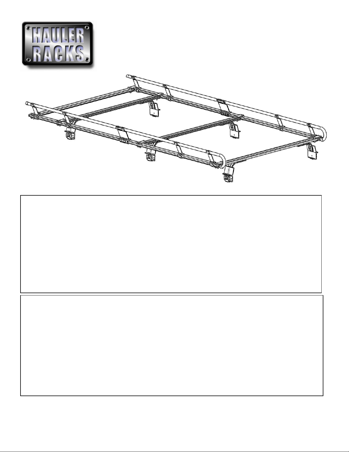
V10SE & V11SE ‘E’ MOUNT RACKS
P/N V10SEV-1 / V11SEV-1
Package Contents:
HARDWARE KIT
(6) CLIPS
(6) CLIP END CAPS
(8) 3/8”-16 x 3” CARRAIGE BOLTS
(16) 3/8”-16 x 2” CARRAIGE BOLTS
(4) 3/8”-16 x 1-3/4” CARRAIGE BOLTS
(4) 3/8”-16 x 1-1/2” HEX BOLTS
(32) 3/8”-16 NUTS
(32) 3/8” SPLIT LOCK WASHERS
(12) 5/16”-18 x 1” CARRIAGE BOLTS
(12) 5/16”-18 NUTS
(12) 5/16” SPLIT LOCK WASHERS
(6) ¼”-20 X 3/4” PHILLPS SCREWS
(6) ¼”-20 X 1-1/2” PHILLPS SCREWS
(6) 1/4” -20 NUTS
(12) ¼” SPLIT LOCK WASHERS
Before you begin:
Remove all components from the shipping carton.
The rack should be assembled on a padded surface such as carpet to prevent scratching of aluminum surfaces. Remove bands
securing components together.
Read the instructions thoroughly to familiarize yourself with the assembly sequence.
Note that you DO NOT tighten any nuts and bolts until the completed rack is installed on the vehicle unless specified. This allows for
minor adjustments to the rack during the installation process.
Gather the following tools used to assemble and install the rack.
9/16” Socket or open end wrench
1/2” Socket or open end wrench
7/16” Socket or open end wrench
Phillips screwdriver
V10SEV-1 shown above
PARTS
(1) RAIL DRIVER’S (LEFT) SIDE ASSEMBLY
(1) RAIL PASSENGER’S (RIGHT) SIDE ASSEMBLY
(1) FRONT RECTANGLULAR CROSSBAR
(1) REAR CROSSBAR
(2) MIDDLE CROSSBAR ASSEMBLIES WITH ‘H’ BRACKETS
(6) CURVED ARMS
(6) E-MOUNTS
HAULER RACKS, INC. Toll Free: 1-800-843-5445
st
7109 31
Minneapolis, MN 55427-2848 Fax: 763-546-0933
Avenue North Phone: 763-546-5620
Page 1 of 10 WWW.HAULERRACKS.COM
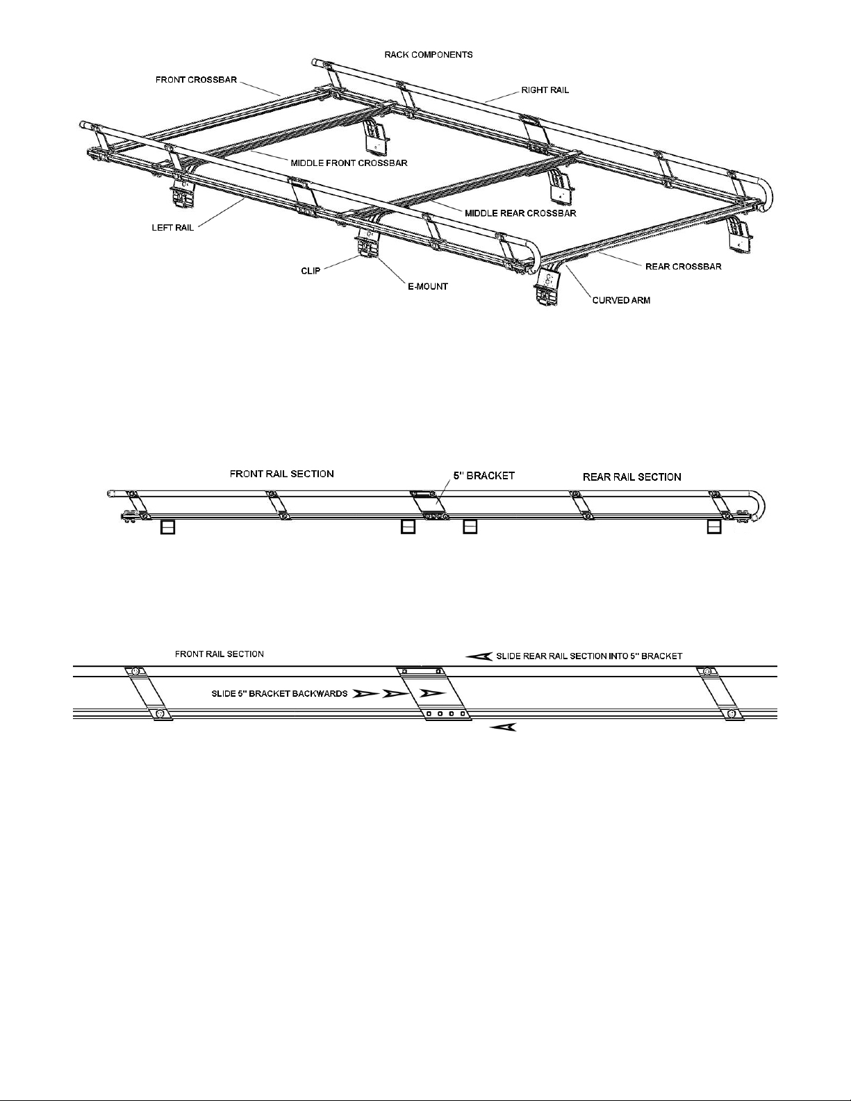
1. Connect front and rear sections
Each side rail side contains a front and rear section preassembled for easier assembly. The front and rear sections are banded
together.
Remove the banding and separate the front and rear rail sections from packaging.
On a flat surface, place boards under the front and rear rail sections as shown so that the ‘H’ brackets does not touch the
ground. This will make aligning the front and rear rail sections faster.
On the front section (the end with the straight round tube), slide the 5” bracket backwards until the two back holes on the 5”
bracket line up with the two holes on the end of the lower rectangle tube.
Insert the rear rail section into the 5” bracket and line up with two remaining holes.
HAULER RACKS, INC. Toll Free: 1-800-843-5445
st
7109 31
Minneapolis, MN 55427-2848 Fax: 763-546-0933
Avenue North Phone: 763-546-5620
Page 2 of 10 WWW.HAULERRACKS.COM
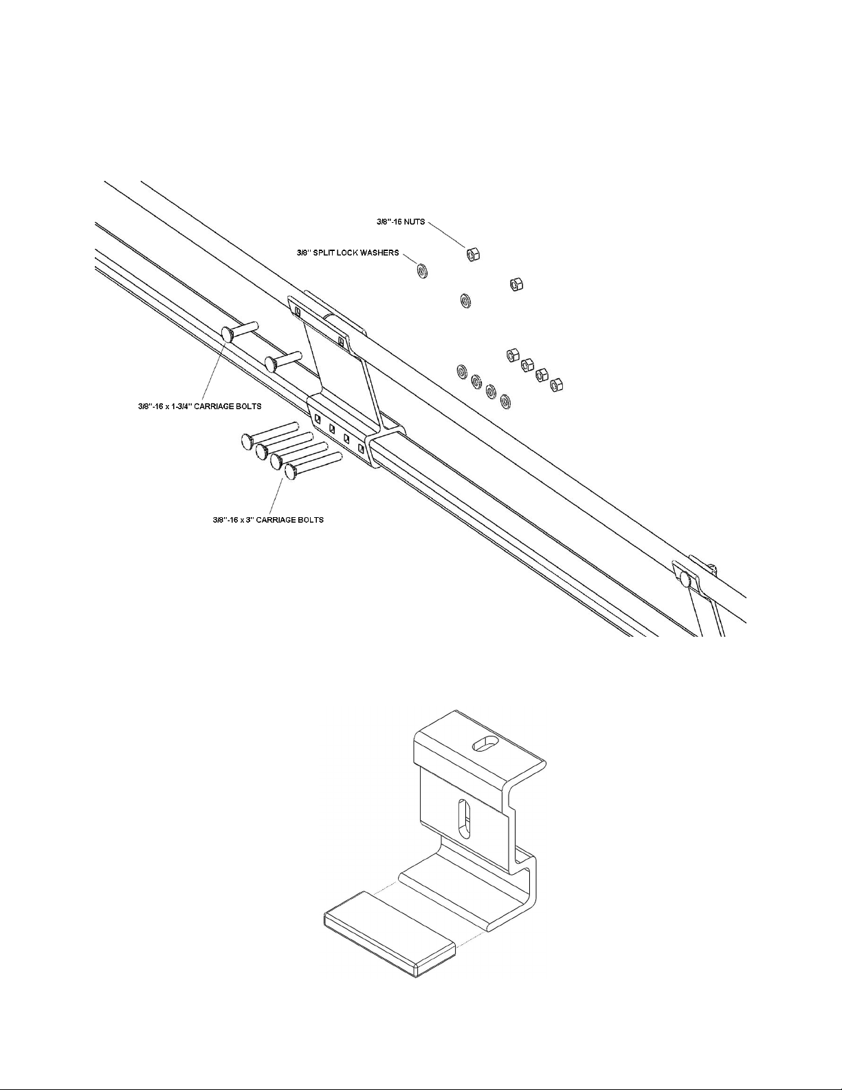
1. (Continued) Connect front and rear sections
Note the orientation of the other carriage bolts on rail assemblies.
For the top round tube, use (2) 3/8”-16 x 1-3/4” carriage bolts, (2) 3/8” split lock washers and (2) 3/8”-16 nuts, install hardware
finger tight. Repeat for other side rail.
For the lower rectangle tube, use (4) 3/8”-16 x 3” carriage bolts, (4) 3/8” split lock washers and (4) 3/8”-16 nuts, install hardware
finger tight. Repeat for other side rail.
2. Assemble Clips
Place the rubber end cap on the clip as shown. Repeat for remaining clips.
HAULER RACKS, INC. Toll Free: 1-800-843-5445
st
7109 31
Minneapolis, MN 55427-2848 Fax: 763-546-0933
Avenue North Phone: 763-546-5620
Page 3 of 10 WWW.HAULERRACKS.COM
 Loading...