

Page 1
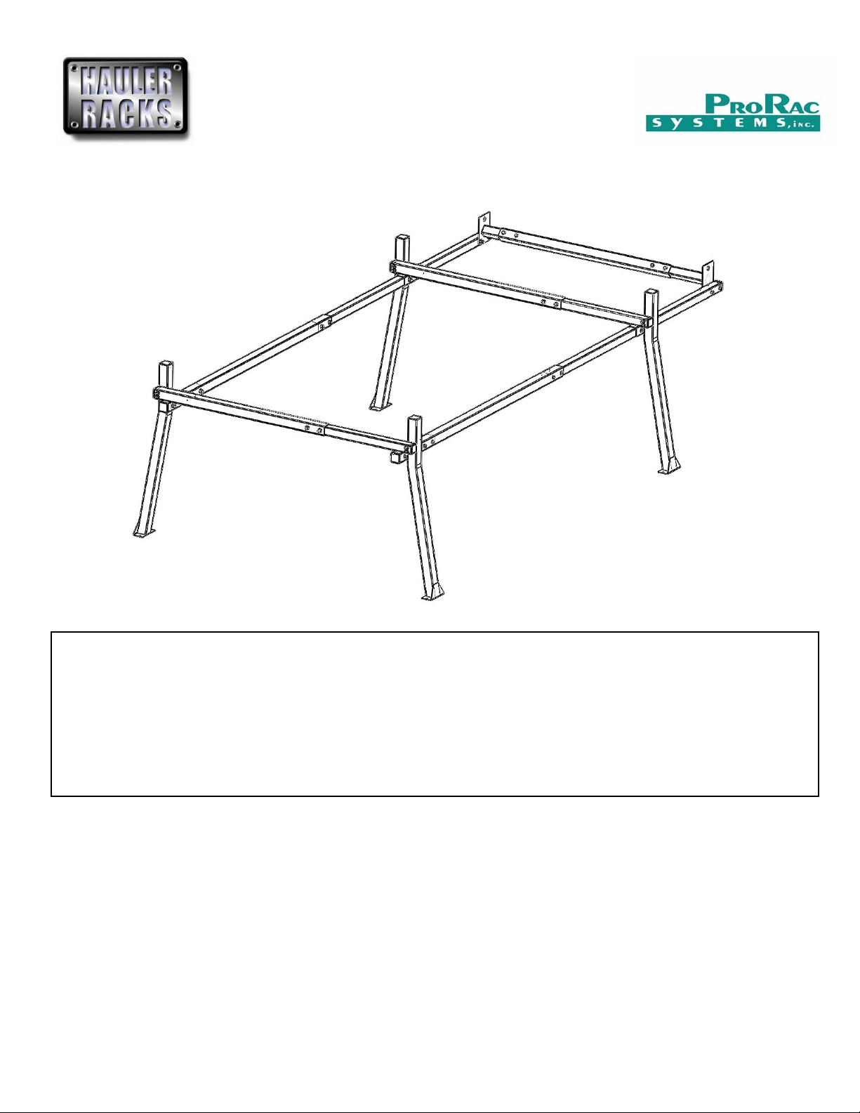
PRORAC CONTRACTOR SERIES
(2)
UNIVERSIAL STEEL TRUCK / CAP RACK
INSTALLATION INSTRUCTIONS
1000 Lb. Capacity Bed Mount
750 Lb. Capacity Cap Mount
Package Contents:
Parts Hardware
(4) Legs (12) 3/8”-16 x 1-1/4” Hex Head Bolts (86) Flat Washers
(4) Camper Plates (28) 3/8”-16 x 2-3/4” Hex Head Bolts (13) 3/8” Split Lock Washers
(2) Outer Crossbars (4) 3/8”-16 x 4-1/2” Hex Head Bolts (36) 3/8”-16 Nylon Insert Locknuts
(2) Inner Crossbars (4) 3/8”-16 x 5” Hex Head Bolts (12) 3/8”-16 Nuts
(2) Front Crossbar Adaptors (1) 3/8”-16 Wing Nut
(1) Middle Front Crossbar (1) Tube of Silicone
(2) Front Rails (8) 2” Square End caps
(2) Rear Rails (4) 1-3/4” Square End caps
Rear Rail Adaptors
Before you begin:
Do not carry more than 1000 pounds (454Kg) for leg mount or 750 pounds (340Kg) for cap mount of combined cargo and accessories on
ProRac crossbars. Distribute loads evenly across both crossbar. ProRac cannot warranty loads that exceed this limit.
Remove all components from the shipping carton and read the instructions thoroughly to familiarize yourself with the assembly sequence.
Gather the following tools used to assemble and install the rack.
9/16” Socket and open end wrench
3/8” dia drill bit and drill
Marker
Tape measure
Tape
HAULER RACKS, INC.
st
7109 31
Minneapolis, MN 55427-2848
WWW.HAULERRACKS.COM
Avenue North
1 of 16
Toll Free: 1-800-843-5445
Phone: 763-546-5620
Fax: 763-546-0933
Page 2
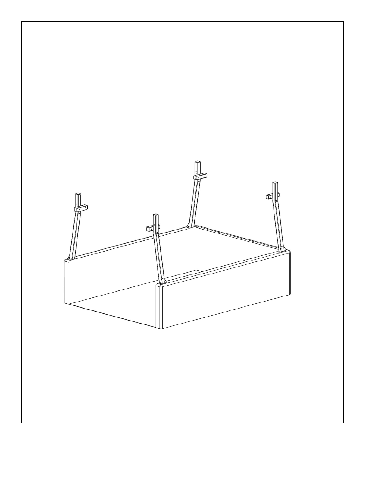
Step 1 – Locate legs on truck bed
Locate on the truck bed where the front and rear legs will be positioned. The ideal positions for the legs are as far
forward for the front legs and as far rearward for the back leg.
You will need to have open access underneath the top of the bed surface for mounting the legs to the bed.
Check for obstructions in mounting the legs to the truck bed such as stake pocket holes or limited access to the
underside of the top surface of the bed.
Check for function of tailgate or interference with the cab of the truck. Adjust as needed.
The spacing between the centers of the bolt holes is 4-1/2”.
Place tape over the desired positions.
Place a leg on top of the tape and position the leg to the desired location on the top surface. For best results, use a
tape measure so each legs is positioned equally with the other side.
Using a marker, mark the outline of the leg and the center of the two mounting holes onto the tape.
Repeat for all legs
HAULER RACKS, INC.
st
7109 31
Minneapolis, MN 55427-2848
WWW.HAULERRACKS.COM
Avenue North
2 of 16
Toll Free: 1-800-843-5445
Phone: 763-546-5620
Fax: 763-546-0933
Page 3
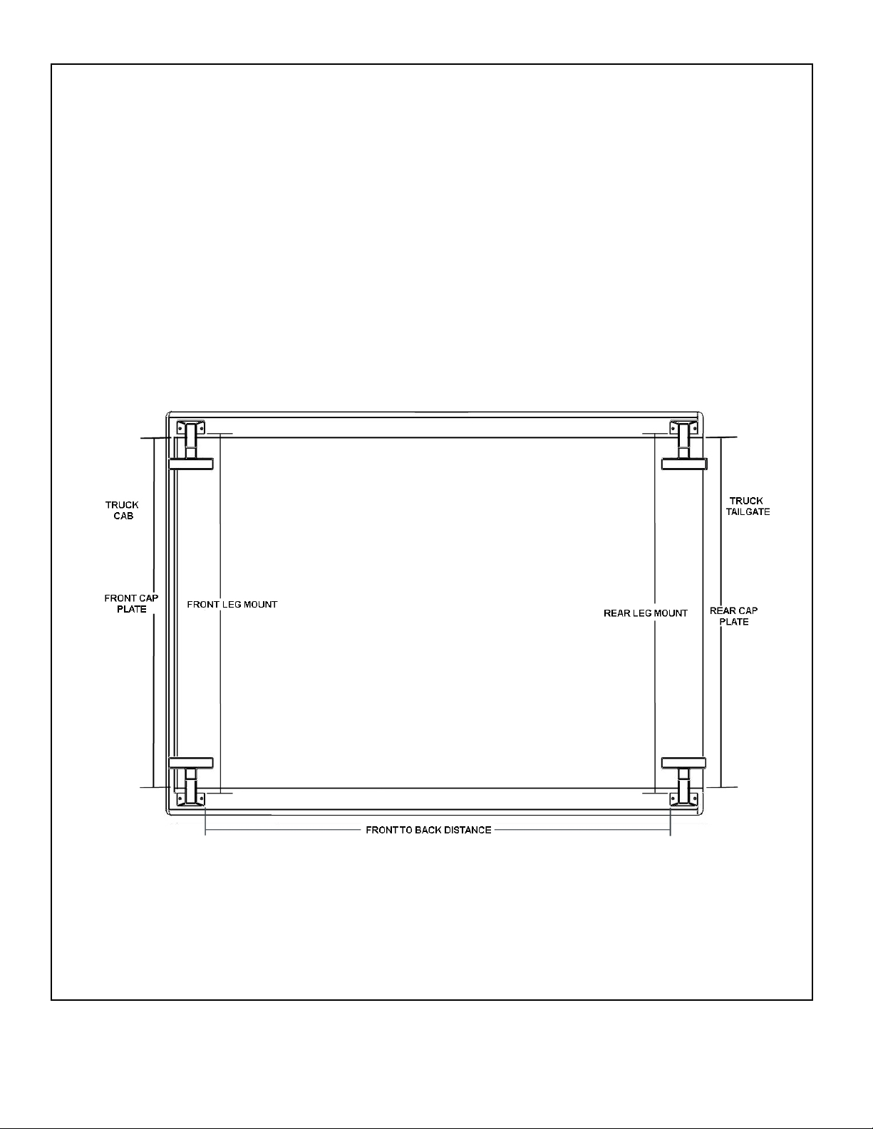
Step 2 Measure distances
Truck Bed Mount
Measure from driver side to passenger side on the inside marked edges of the tape where the legs where outline
from step 1. See illustration below.
Cap Plate Mount
Measure from driver side to passenger side inside edges of the bed rail. See illustration below.
Front truck leg or cap mount span = _____________________
Rear truck leg or cap mount span = _____________________
Measure the distance between the marked inside edges of the legs front to back and record the value belo w.
Inside span between front and rear legs = _____________
From the measurements above
Front cap bed mount span +12” = ___________
Rear cap bed mount span +12” = ___________
HAULER RACKS, INC.
st
7109 31
Minneapolis, MN 55427-2848
WWW.HAULERRACKS.COM
Avenue North
3 of 16
Toll Free: 1-800-843-5445
Phone: 763-546-5620
Fax: 763-546-0933
Page 4
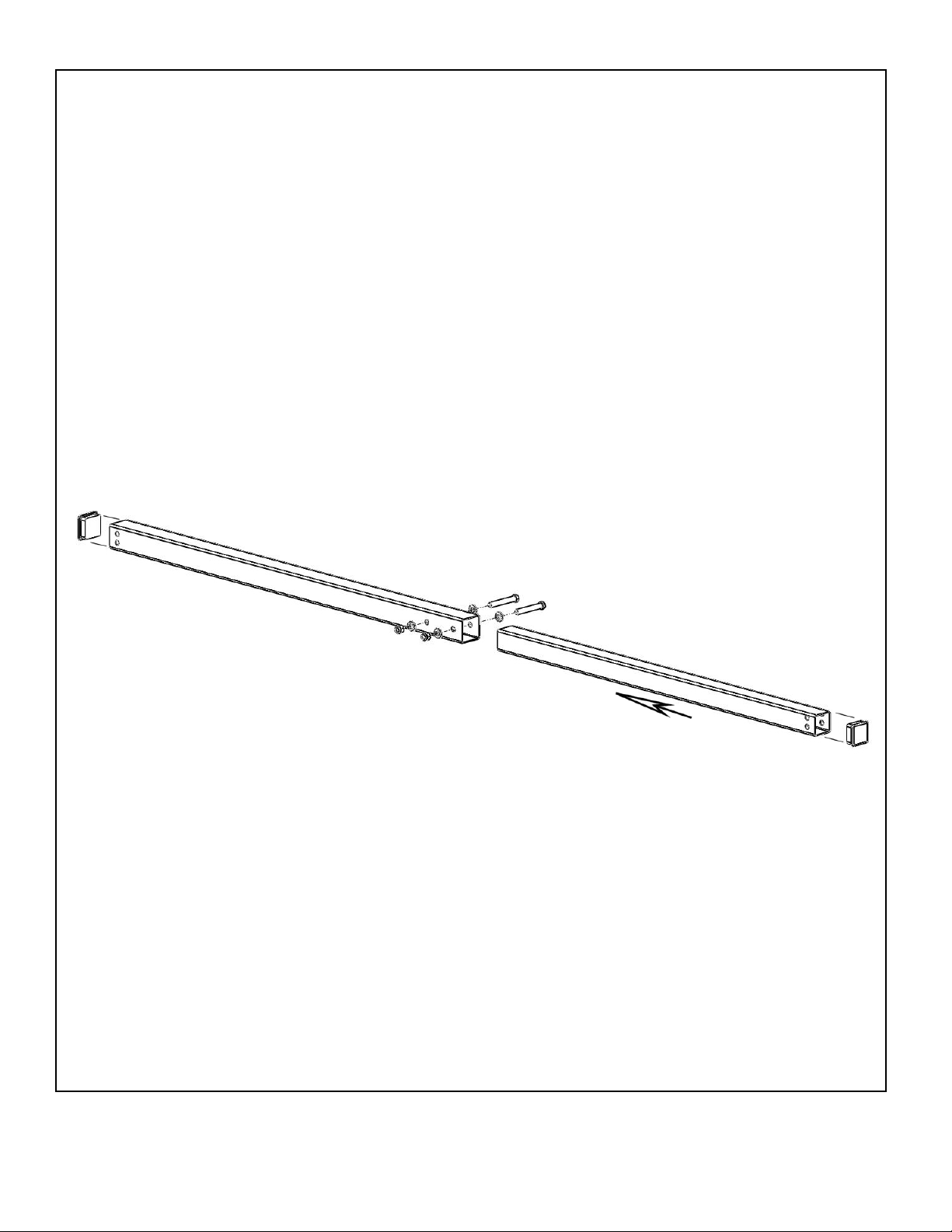
Step 3 Crossbar assembly
Crossbar width fit
Because truck beds widths can taper front to back, each crossbar will be set specifically to match where it is mounted
on the bed. The crossbar width will be 5-1/4” shorter than the length measured.
Using the measurements from step 2,
Front Legs span ___________________ - 5-1/4” = _________________
Rear Legs span ____________________ - 5-1/4” = _____ ____________
Slide the 1-3/4” inner crossbar tube into the 2” out crossbar tube as shown until they measure the length from above.
Temporarily secure the two crossbars together by wrapping tape around the end of the 2” outer crossbar and 1-3/4”
inner crossbar.
Using the 2” tube bolt holes as guides; mark the center of the holes using a center punch.
Drill the holes marked with a 3/8” drill bit on both sides. Remove tape that was temporarily holding the two crossbars
together.
Align the bolt holes of both tubes. Apply a small bead of silicone around the bolt holes on the larger tube.
Insert the 3/8”-16 x 2-3/4” bolt with a flat washer through the crossbar.
Secure the bolt with a flat washer and 3/8”-16 nylon insert lock nut.
Repeat for other bolt hole.
Place the end caps on the ends of the crossbar.
Apply silicone to the gap between the inner and outer crossbar to seal out water and reduce wind noise.
Repeat step for other crossbar.
HAULER RACKS, INC.
st
7109 31
Minneapolis, MN 55427-2848
WWW.HAULERRACKS.COM
Avenue North
4 of 16
Toll Free: 1-800-843-5445
Phone: 763-546-5620
Fax: 763-546-0933
Page 5
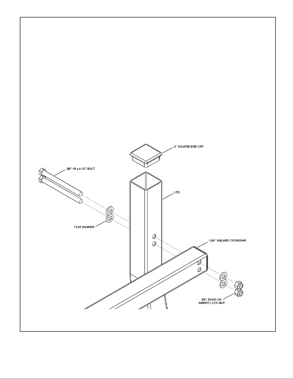
Step 4 Crossbar to leg assembly
Note: Rail pass through tube on leg is not shown for exploded view clarity.
You may mount to either the front side or rear side of the legs.
Orientate the 1-3/4” tube as shown (note the holes are not centered on this end of the crossbar)
Starting with the bottom hole first, insert the 3/8”-16 x 4-1/2” bolt with a flat washer through the leg and 1-3/4” square
crossbar.
Secure the bolt with a flat washer and 3/8”-16 nylon insert lock nut.
Note the spacing between the washer fit is tight, it maybe necessary to adjust the washer centering so they will both
fit flush on the legs and crossbars.
Repeat for other bolt hole.
Lightly tighten the hardware.
Insert the 2” square end cap into the top of the leg.
HAULER RACKS, INC.
st
7109 31
Minneapolis, MN 55427-2848
WWW.HAULERRACKS.COM
Avenue North
5 of 16
Toll Free: 1-800-843-5445
Phone: 763-546-5620
Fax: 763-546-0933
Page 6
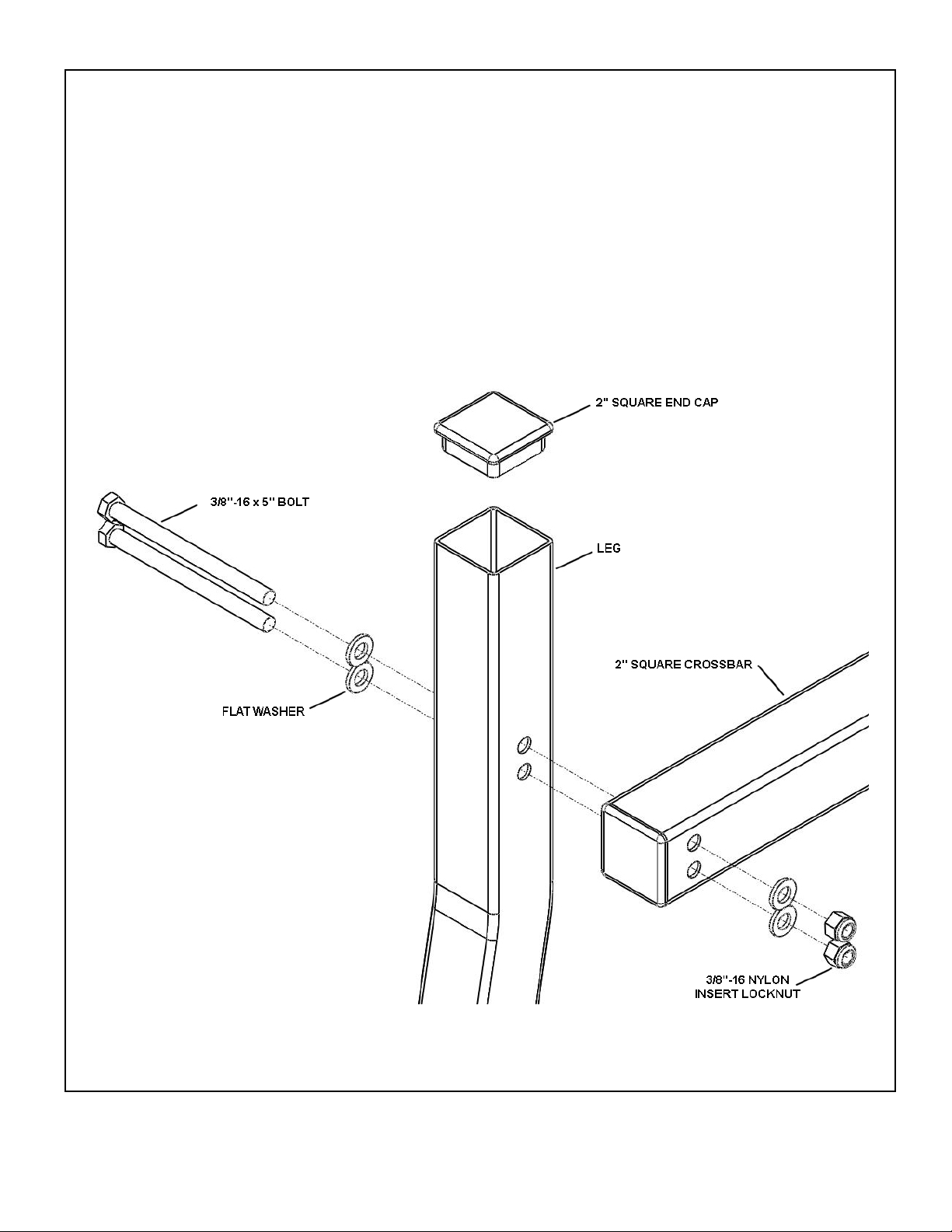
Step 4 (continued) Crossbar to leg assembly
Note: Rail pass through tube on leg is not shown for exploded view clarity.
Orientate the 2” tube as shown (note the holes are not centered on this end of the crossbar)
Starting with the bottom hole first, insert the 3/8”-16 x 5” bolt with a flat washer through the leg and 2” square
crossbar.
Note the spacing between the washer fit is tight, it maybe necessary to adjust the washer centering so they will both
fit flush on the legs and crossbars.
Secure the bolt with a flat washer and 3/8”-16 nylon insert lock nut.
Repeat for other bolt hole.
Insert the 2” square end cap into the top of the leg.
Lightly tighten the hardware.
HAULER RACKS, INC.
st
7109 31
Minneapolis, MN 55427-2848
WWW.HAULERRACKS.COM
Avenue North
6 of 16
Toll Free: 1-800-843-5445
Phone: 763-546-5620
Fax: 763-546-0933
Page 7
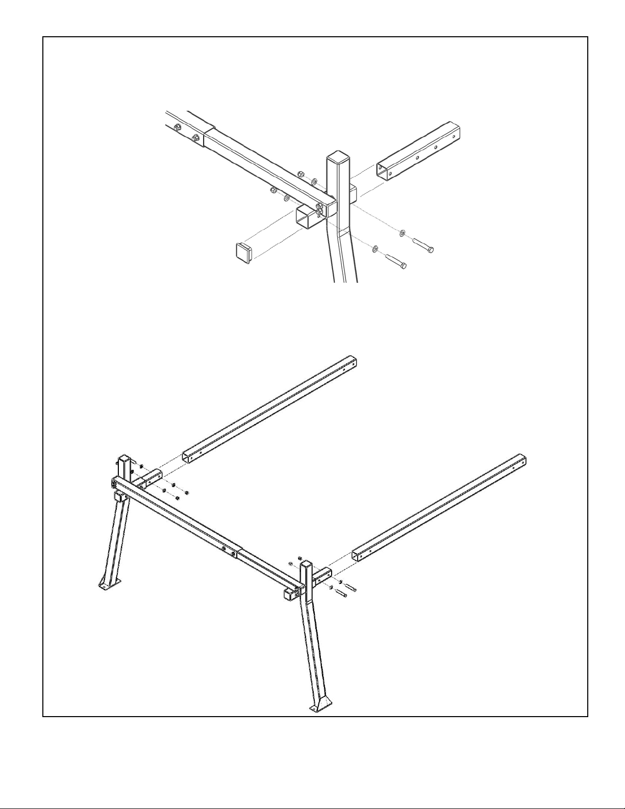
Step 5 Rear leg subassembly
On the rear legs, slide the 1-3/4” x 12” tube adaptor into the rail tube and align the bolt holes and secure with (2) 3/8”16 x 2-3/4” bolts, (4) flat washers and (2) 3/8”-16 nylon insert lock nuts.
Place 2” square end caps on the rear of the leg and top of leg. Repeat for other leg.
Step 6 Rear Rail assembly
Slide the 2” square tubing rear rail section onto the rear leg subassembly. Align the bolt holes and secure with (with
(2) 3/8”-16 x 2-3/4” bolts, (4) flat washers and (2) 3/8”-16 nylon insert lock nuts.
Repeat for other side.
HAULER RACKS, INC.
st
7109 31
Minneapolis, MN 55427-2848
WWW.HAULERRACKS.COM
Avenue North
7 of 16
Toll Free: 1-800-843-5445
Phone: 763-546-5620
Fax: 763-546-0933
Page 8
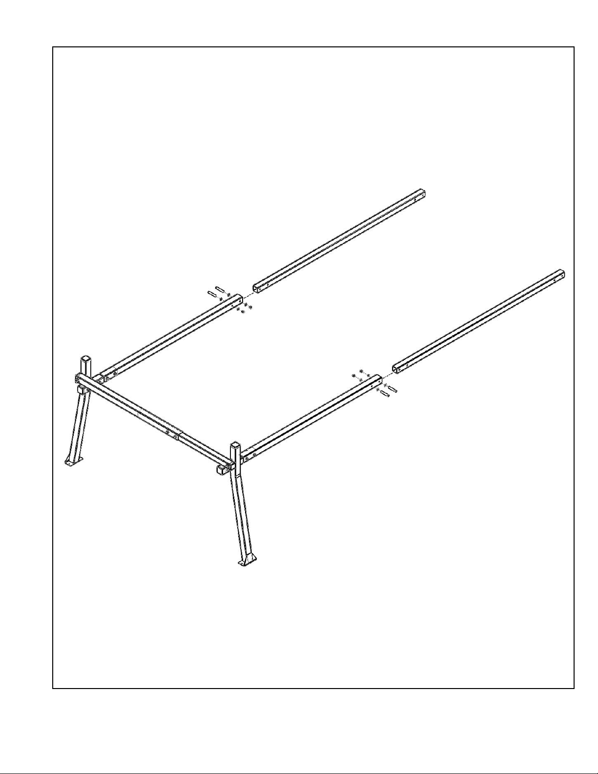
Step 7 Front Rail assembly
Slide the front rail through the front legs and line up the bolt holes for 10’ length.
If a shorter length is desired, slide the front rail into the rear rail to the desired position. Mark the holes. Remove
front rail and drill holes. Reinsert the front rail into the rear and line up holes.
Align the bolt holes and secure with (with (2) 3/8”-16 x 2-3/4” bolts, (4) flat washers and (2) 3/8”-16 nylon insert lo ck
nuts.
Seal the gap between the rails with silicone.
Repeat for other side.
Insert 1-3/4” square end caps into the front rails.
HAULER RACKS, INC.
st
7109 31
Minneapolis, MN 55427-2848
WWW.HAULERRACKS.COM
Avenue North
8 of 16
Toll Free: 1-800-843-5445
Phone: 763-546-5620
Fax: 763-546-0933
Page 9
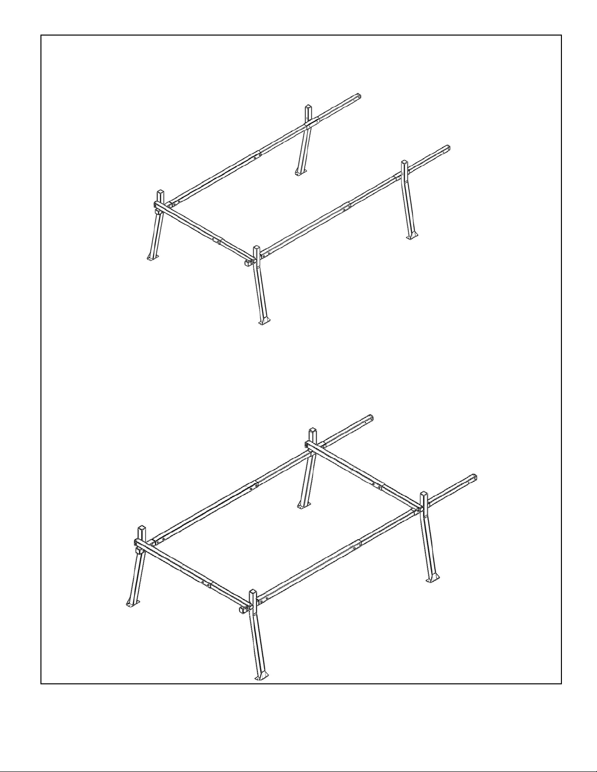
Step 7 Front leg to front rail assembly
Slide the front legs on front rail. Adjust the span between the front and rear legs so the distance matche s the
measured spacing above.
Temporarily secure the front legs to the rails with tape as shown. This will allow you to set the rack on the vehicle
and adjust for final fit.
Mount the middle crossbar to the front legs using hardware as used for mounting the rear crossbar to the rear legs.
Adjust the legs to crossbar so the leg feet are flush with the ground.
Tighten the crossbar to leg hardware.
HAULER RACKS, INC.
st
7109 31
Minneapolis, MN 55427-2848
WWW.HAULERRACKS.COM
Avenue North
9 of 16
Toll Free: 1-800-843-5445
Phone: 763-546-5620
Fax: 763-546-0933
Page 10
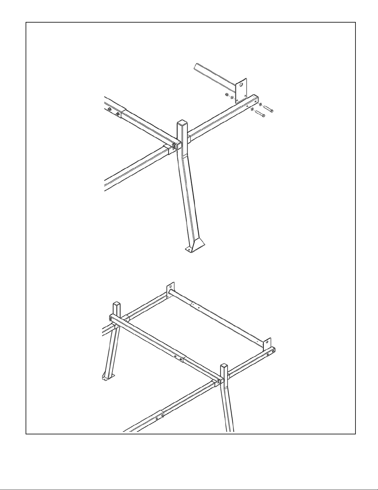
Step 8 Front Crossbar assembly
Loosely bolt one end of the front crossbar rail adaptor to a rail with (2) 3/8”-16 x 2-3/4” bolts, (4) flat washers and (2)
3/8”-16 nylon insert lock nuts.
.
Slide the front crossbar middle tube onto the front crossbar rail adaptor and push it so it is close to the front rail.
Slide the other front crossbar rail adaptor into the front middle crossbar tube and then loosely bolt it to the front rail
with (2) 3/8”-16 x 2-3/4” bolts, (4) flat washers and (2) 3/8”-16 nylon insert lock nuts.
st
7109 31
Minneapolis, MN 55427-2848
WWW.HAULERRACKS.COM
Avenue North
HAULER RACKS, INC.
10 of 16
Toll Free: 1-800-843-5445
Phone: 763-546-5620
Fax: 763-546-0933
Page 11
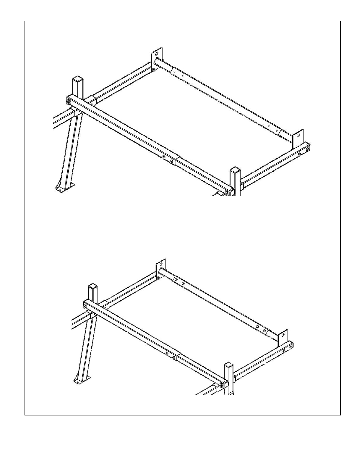
Step 8 (continued) Front Crossbar assembly
Center the front middle crossbar tube between the front rail crossbar adaptors. For best results, use a tape measure.
Temporally secure the middle crossbar to front rail crossbar adaptors with tape. This will keep the middle crossbar in
place while drilling holes to secure it to the rail adaptors. Tighten the hardware for the front rail adaptors.
Locate the center of the front middle crossbar marked holes and use a center punch. Drill the 3/8” holes on both
sides. Repeat for all holes.
Secure with (4) 3/8”-16 x 2-3/4” bolts, (8) flat washers and (4) 3/8”-16 nylon insert lock nuts.
and apply a small silicone bead around the bolt holes before putting on the flat washers.
Remove the tape and seal the gap between the crossbars on both sides with silicone.
HAULER RACKS, INC.
st
7109 31
Minneapolis, MN 55427-2848
WWW.HAULERRACKS.COM
Avenue North
11 of 16
Toll Free: 1-800-843-5445
Phone: 763-546-5620
Fax: 763-546-0933
Page 12
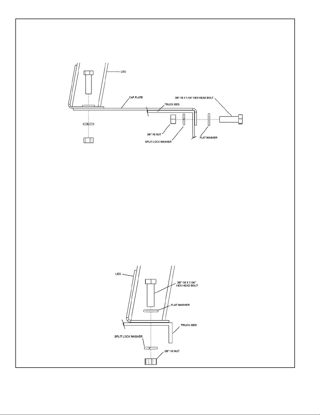
Step 9 Rack placement on bed
CAP PLATES
If using a cap plates, bolt the plate to the leg using (2) 3/8”-16 x 1-1/4 bolts, (2) flat washer, (2) split lock washers and
(2) 3/8-16 nuts. Repeat for remaining plates and legs.
With an assistant place on the vehicle and align to desired position.
Using the cap plate side bolt hole as a guide, drill a 3/8” hole through the truck bed side rail wall.
Apply a small bead of silicone around the drilled hole.
Bolt the plate to the truck bed with a 3/8”-16 x 1-1/4” bolt, flat washer, split lock washer and 3/8”-16 nut. Repeat for
remaining cap plates.
TRUCK BED MOUNT
Drill out the holes marked on the tape with a 3/8” drill and remove tape from the truck bed. Apply a small bead of
silicone around the drilled holes.
With an assistant, lift the rack and place on the bed of the truck and align the bolt holes in the leg feet with the holes
drilled in the bed.
Loosely secure the legs to the bed with (2) 3/8”-16 x 1-1/4” bolts, (2) flat washers, (2) split lock washers and (2) 3/8”16 nuts.
HAULER RACKS, INC.
st
7109 31
Minneapolis, MN 55427-2848
WWW.HAULERRACKS.COM
Avenue North
12 of 16
Toll Free: 1-800-843-5445
Phone: 763-546-5620
Fax: 763-546-0933
Page 13
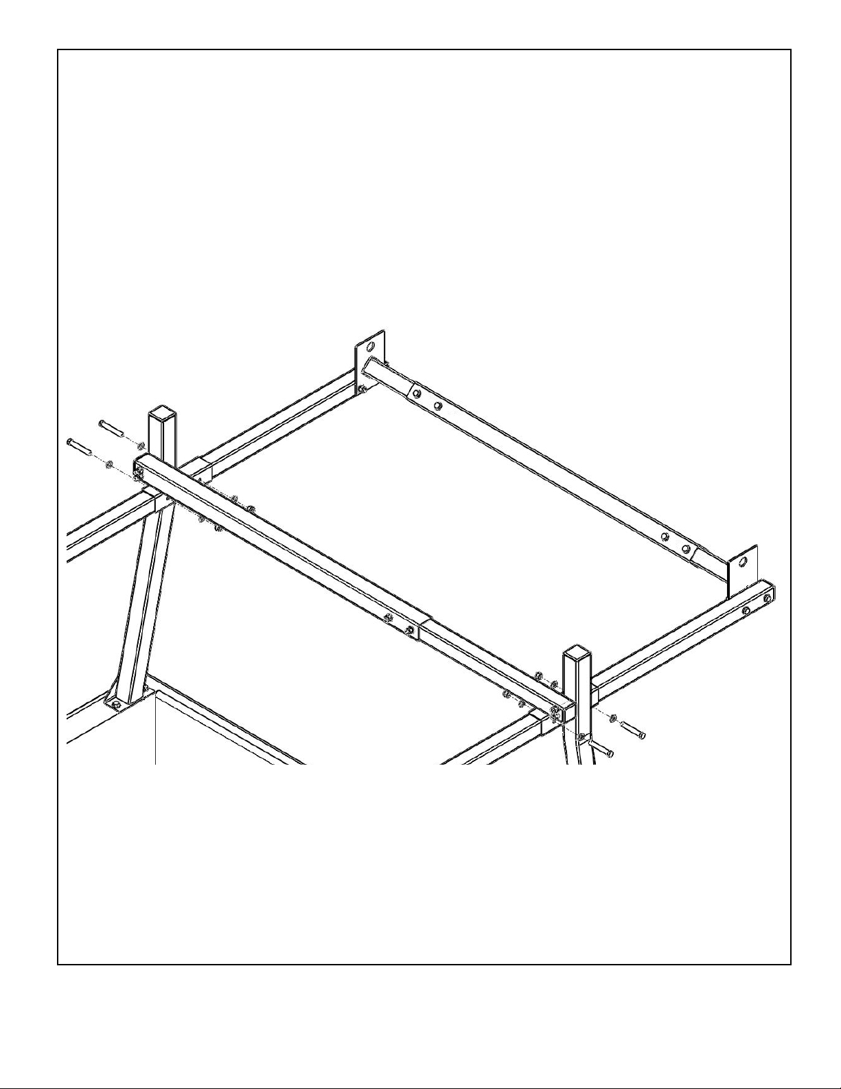
Step 10 Front Leg to front rail
Remove the tape from the front leg rail pass through tubes and adjust the front legs so they are perpendi cular to the
rails.
Check that the legs to crossbar assembly is square and tighten the hardware, starting with the cro s sbar bolts and
then proceeding to the legs.
Locate the center of the holes on the front legs rail pass through tube marked holes and use a center punch
Drill a 3/8” holes on one side and insert a 3/8” bolt through the leg and into the rail to hold the leg to rail assembly in
place and continue to drill the other (3) holes.
Secure with hardware and apply silicone to the flat washers.
Tighten the leg hardware.
Repeat for other side.
Seal the gap of the front rail and the rail pass through tubes with silicone.
Check to make sure the crossbar is square to the upper portion of the legs. Adjust as needed and then tighten the
hardware.
Go around rack and check and tighten all hardware.
HAULER RACKS, INC.
st
7109 31
Minneapolis, MN 55427-2848
WWW.HAULERRACKS.COM
Avenue North
13 of 16
Toll Free: 1-800-843-5445
Phone: 763-546-5620
Fax: 763-546-0933
Page 14
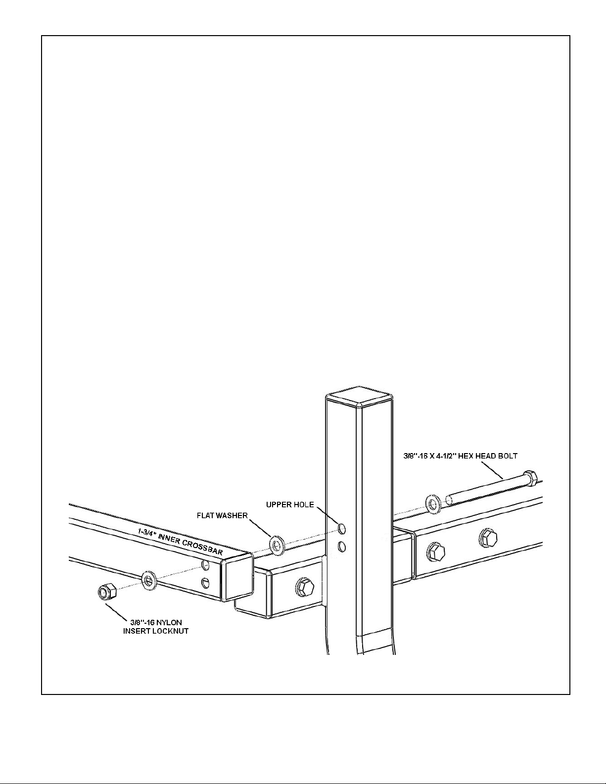
Removable rear cross bar option.
The rear crossbar can be removed or pivot out of the way when loading tall upright cargo into the truck bed.
Removal
To remove the rear crossbar - unbolt the crossbar from the leg on both sides.
NOTE: Always have the crossbar secured with all bolts on both ends when using the vehicle.
Pivoting crossbar
Note! This feature should only be used when a load is not carried on the crossbars. If a
load is going to be carried on the crossbars, all four bolts must be used to secure the
crossbar to the legs!
To change the rack for pivoting the rear crossbar, remove the hardware holding the rear crossbar in place.
On the end with the 1-3/4” inner crossbar, use a 4-1/2” bolt with flat washer and slide them through the upper hole of
the leg.
Place a flat washer on the 4-1/2” bolt and move it to so it contacts the leg.
Place the crossbar onto the bolt and slide towards the leg.
Secure the crossbar to the leg using a flat washer and nylon insert lock nut.
Tighten the nut and bolt enough so the crossbar can be rotated around the bolt but not binding.
HAULER RACKS, INC.
st
7109 31
Minneapolis, MN 55427-2848
WWW.HAULERRACKS.COM
Avenue North
14 of 16
Toll Free: 1-800-843-5445
Phone: 763-546-5620
Fax: 763-546-0933
Page 15
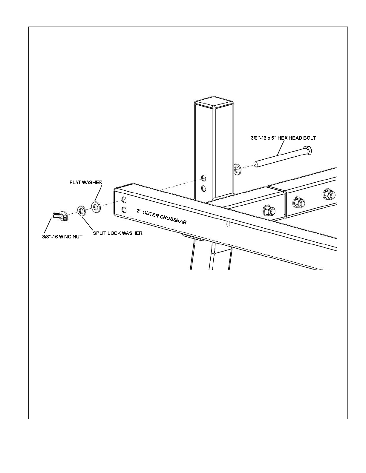
Removable rear cross bar pivot continued.
On the end with the 2” outer crossbar, use a 5” bolt with flat washer and slide them through the upper hole of the leg.
Place the crossbar onto the bolt and slide towards the leg.
Secure the crossbar to the leg using a flat washer, split lock washer and wing nut.
Tighten the wing nut enough to flatten the split lock washer.
NOTE: Always check so make sure the wing nut is tight before and during use. If the wing nut loosens,
replace by removing the split lock washer and use a 3/8”-16 nylon insert lock nut.
NOTE: Always have the crossbar secured on both ends when using the vehicle.
HAULER RACKS, INC.
st
7109 31
Minneapolis, MN 55427-2848
WWW.HAULERRACKS.COM
Avenue North
15 of 16
Toll Free: 1-800-843-5445
Phone: 763-546-5620
Fax: 763-546-0933
Page 16

Customer Limited Warranty and Standard Return Policy
Hauler Racks, Inc. offers to preferred customers a special limited warranty. It is our goal to provide effective service for
any warranty or standard return. This statement of warranty and return policy is divided into two sections: Warranty
Returns of Defective Product and Standard Returns of Unused Product.
Warranty Returns of Defective Product
Hauler Racks, Inc. will repair or replace, at its option and without charge, any properly installed Hauler component that
fails due to defect in material or workmanship up to 30 days from the initial registered consumer purchase. All of our
aluminum product line is guaranteed not to rust or corrode for 1 year. Proof of Purchase must be provided for warranty
to be honored.
Loads should never exceed 1/3 of your vehicle’s manufacturer’s total load capacity. Loads should never extend more
than 1 foot on either end of rack. This warranty is void if any damage to the product is due to misuse, abuse, neglect,
accident, improper installation, or any uses contrary to the instructions accompanying the product. The warranty is also
void if racks are altered in any manner. The racks have been load tested for the racks capacity to hold loads when not
on a vehicle. Hauler Racks, Inc. does not warranty load capacities. As the factory has no way of knowing if the product
was properly assembled, installed, used according to instructions, or if loads were secured properly.
This warranty covers the cost of the defective component and not the cost of removal, installation or other incidental
charges unless other arrangements have been made with Hauler Racks.
This warranty gives you specific legal rights and you may have other rights which vary from state to state.
All warranty claims must receive a Return Authorization number from Hauler Racks, Inc. BEFORE the product is
returned to the Company. Please follow this procedure:
1. Call Hauler at 800-843-5445 to request a Return Authorization number. You will need to provide the following
information
• Specific nature of the defect • Product installation date
• Product part number • Original sales invoice number
2. When a replacement or repair strategy is determined, a Return Authorization number will be assigned to the claim.
3. A replacement invoice and shipping document will be generated at Hauler Racks to initiate any replacement product.
Replacement product will be sent according to standard shipping cycles.
4. The purchaser is responsible for packing and return shipping of the product. The RETURN AUTHORIZ ATION
NUMBER MUST BE CLEARLY MARKED ON THE OUTSIDE OF THE PACKAGE. Unmarked packages will be
refused. Any product damage that occurs during the shipping is not covered under warranty. The purchaser must
pursue claims for shipping damage with the shipping center.
5. The purchaser is responsible for payment of both the original product invoice and the replacement invoice according
to established credit terms.
6. Upon receipt of the returned product, Hauler Racks will review the claim for warranty conformance. If the claim meets
warranty criteria, a credit for the original invoice amount will be posted to the purchaser’s account and a credit memo
will be mailed. If the claim does not meet warranty criteria, the purchaser will receive a statement detailing reasons
for partial credit or denial. At the purchaser’s option, denied product may be returned to the purchaser.
Standard Returns of Unused Product
Unused product may be eligible for return to Hauler Racks, Inc. Follow the procedure described in the section on
Warranty Returns to receive an Authorization Number.
Returned product which is less than 6 (six) months old is subject to a 20% restocking fee.
Returned product which is more than 6 (six) months old may not be eligible for return or may incur additional restocking
charges.
© 2009 Hauler Racks, Inc. Revised 5-12-2009
HAULER RACKS, INC.
st
7109 31
Minneapolis, MN 55427-2848
WWW.HAULERRACKS.COM
Avenue North
16 of 16
HMIS37
Steel Truck / Cap Rack
Toll Free: 1-800-843-5445
Phone: 763-546-5620
Fax: 763-546-0933
 Loading...