

Page 1

hatcocorp.com
Register Online!
(see page 2)
S’inscrire en ligne!
(voir page 28)
Remote Cold Shelves Built-In
Plaques réfrigérantes encastrables
contrôlées à distance
CSUR, CSBFR, CSSBR, CSSBFR, CSUX,
CSBFX, CSSBX, and CSSBFX Series/Série
Installation and Operating Manual
Manuel d’installation et d’utilisation
WARNING
Do not operate this equipment unless you
have read and understood the contents
of this manual! Failure to follow the
instructions contained in this manual
may result in serious injury or death.
This manual contains important safety
information concerning the maintenance,
use, and operation of this product. If
you’re unable to understand the contents
of this manual, please bring it to the
attention of your supervisor. Keep this
manual in a safe location for future
reference.
English = p 2
P/N 07.04.835.00 © 2017 Hatco Corporation
ADVERTENCIA
No opere este equipo al menos que haya
leído y comprendido el contenido de este
manual! Cualquier falla en el seguimiento
de las instrucciones contenidas en
este manual puede resultar en un serio
lesión o muerte. Este manual contiene
importante información sobre seguridad
concerniente al mantenimiento, uso y
operación de este producto. Si usted
no puede entender el contenido de
este manual por favor pregunte a su
supervisor. Almacenar este manual en
una localización segura para la referencia
futura.
AVERTISSEMENT
Ne pas utiliser cet équipement sans avoir
lu et compris le contenu de ce manuel ! Le
non-respect des instructions contenues
dans ce manuel peut entraîner de
graves blessures ou la mort. Ce manuel
contient des informations importantes
concernant l’entretien, l’utilisation et le
fonctionnement de ce produit. Si vous ne
comprenez pas le contenu de ce manuel,
veuillez le signaler à votre supérieur.
Conservez ce manuel dans un endroit
sûr pour pouvoir vous y référer plus tard.
Français = p 28
Page 2

CAUTION
CONTENTS
English
Important Owner Information .............................................. 2
Introduction ...........................................................................2
Important Safety Information .............................................. 3
Model Designation ...............................................................4
Model Description ................................................................5
Specifications ....................................................................... 6
Electrical Rating Charts ....................................................... 6
Refrigerant Information ........................................................ 9
Dimensions ........................................................................ 10
Installation ...........................................................................13
General .............................................................................. 13
Preparing the Installation Site ...........................................13
Installing a Top Mounted Unit ............................................14
Countertop Cutout Dimensions—Top Mounted Units .......14
Countertop Cutout and Mounting Bolt Dimensions—
Bottom Mounted Units ..................................................... 15
Installing a Bottom Mounted Unit ......................................16
Installing an Under Mounted Unit ...................................... 17
IMPORTANT OWNER INFORMATION
Record the model number, serial number, voltage, and
purchase date of the unit in the spaces below (specification
label located on the side of the control enclosure). Please
have this information available when calling Hatco for service
assistance.
Model No. ________________________________________
Serial No. _________________________________________
Voltage ___________________________________________
Date of Purchase ___________________________________
Register your unit!
Completing online warranty registration will prevent delay in
obtaining warranty coverage. Access the Hatco website at
www.hatcocorp.com, select the Parts & Service pull-down
menu, and click on “Warranty Registration”.
Mounting Bolt Dimensions ................................................. 19
Connecting the Components ............................................. 20
Installing the Control Enclosure Remotely ........................21
Operation .............................................................................22
General .............................................................................. 22
Changing the Setpoint Temperature ..................................23
Setting the Auto-Defrost Cycle ..........................................23
Changing Fahrenheit and Celsius Setting .........................23
Maintenance ........................................................................ 24
General .............................................................................. 24
Daily Cleaning ...................................................................24
Cleaning the Stone Surface
(CSSB and CSSBF Models) ...........................................25
Monthly Cleaning ............................................................... 25
Troubleshooting Guide ......................................................26
Options and Accessories .................................................. 27
Limited Warranty ................................................................27
Authorized Parts Distributors ........................... Back Cover
Business
Hours: 7:00 am to 5:00 pm Central Standard Time (CST)
(Summer Hours: June to September—
7:00 am to 5:00 pm CST Monday–Thursday
7:00 am to 4:00 pm CST Friday)
Telephone: 800-558-0607; 414-671-6350
e-mail: partsandservice@hatcocorp.com
24 Hour 7 Day Parts and Service
Assistance available in the United States
and Canada by calling 800-558-0607.
Additional information can be found by visiting our web site at
www.hatcocorp.com.
INTRODUCTION
Hatco Remote Cold Shelves Built-In are specially designed to
hold chilled foods at safe serving temperatures. The insulated,
top mount or bottom mount units are available in several sizes.
The components of the Remote Cold Shelves are shipped as
separate pieces that require field installation and connection.
This provides the end user greater installation flexibility than
self-contained units. The components include a cold shelf, a
control panel, and a condensing unit. One year parts and onsite labor warranty is standard.
Hatco Remote Cold Shelves Built-In are products of extensive
research and field testing. The materials used were selected
for maximum durability, attractive appearance, and optimum
performance. Every unit is inspected and tested thoroughly
prior to shipment.
This manual provides the installation, safety, and operating
instructions for Remote Cold Shelves Built-In. Hatco
recommends all installation, operating, and safety instructions
appearing in this manual be read prior to installation or
operation of the unit.
Safety information that appears in this manual is identified by
the following signal word panels:
WARNING
WARNING indicates a hazardous situation which, if not
avoided, could result in death or serious injury.
CAUTION indicates a hazardous situation which, if not
avoided, could result in minor or moderate injury.
NOTICE
NOTICE is used to address practices not related to
personal injury.
2
Form No. CSRM-0817
Page 3

English
CAUTION
IMPORTANT SAFETY INFORMATION
Read the following important safety information before using this equipment to avoid serious
injury or death and to avoid damage to equipment or property.
WARNING
ELECTRIC SHOCK HAZARD:
• Plug unit into a properly grounded electrical receptacle
of the correct voltage, size, and plug configuration. If
plug and receptacle do not match, contact a qualified
electrician to determine and install proper voltage and
size electrical receptacle.
• Turn OFF power switch and unplug power cord before
performing any cleaning, adjustments, or maintenance.
• Unit is not weatherproof. Locate unit indoors.
• Control enclosure must be mounted in a vertical
surface. Mounting control enclosure in a horizontal
surface may result in the collection of liquids and lead
to electric shock.
• DO NOT submerge or saturate with water. Unit is not
waterproof. Do not operate if unit has been submerged
or saturated with water.
• This unit is not “jet-proof” construction. Do not use
jet-clean spray to clean this unit.
• Do not steam clean or use excessive water on unit.
• Discontinue use if power cord is frayed or worn.
• Do not attempt to repair or replace a damaged power
cord. Cord must be replaced by an Authorized Hatco
Service Agent or a person with similar qualifications.
• This unit must be serviced by qualified personnel only.
Service by unqualified personnel may lead to electric
shock or burn.
• Use only Genuine Hatco Replacement Parts when
service is required. Failure to use Genuine Hatco
Replacement Parts will void all warranties and may
subject operators of the equipment to hazardous
electrical voltage, resulting in electrical shock or burn.
Genuine Hatco Replacement Parts are specified to
operate safely in the environments in which they are
used. Some aftermarket or generic replacement parts
do not have the characteristics that will allow them to
operate safely in Hatco equipment.
FIRE HAZARD:
• Install condensingunitwithaminimumof2″(51mm)
of space between all sides of unit and any combustible
surfaces.
• Do not use flammable cleaning solutions to clean this
unit.
EXPLOSION HAZARD: Do not store or use gasoline or
other flammable vapors or liquids in the vicinity of this or
any other appliance.
Make sure food product and food pans have been chilled
to the proper food-safe temperature before placing on
unit. Failure to chill food product properly may result in
serious health risks. This unit is for holding pre-chilled
food product only.
This unit is for holding food for short periods of time.
Never hold food longer than 4 hours.
WARNING
Hatco Corporation is not responsible for actual food
product serving temperature. It is the responsibility of the
user to ensure that food product is held and served at a
safe temperature.
Maintain proper cleanliness of unit. Proper cleanliness and
sanitation is critical for food-safe operation. Refer to the
MAINTENANCE section for cleaning procedures.
Do not place food product directly onto hardcoat or
simulated stone surface. Food product must be wrapped,
boxed, or on a food pan.
This unit is not intended for use by children or persons
with reduced physical, sensory, or mental capabilities.
Ensure proper supervision of children and keep them
away from the unit.
Make sure all operators have been instructed on the safe
and proper use of the unit.
This unit has no “user-serviceable” parts. If service
is required on this unit, contact an Authorized Hatco
Service Agent or contact the Hatco Service Department at
800-558-0607 or 414-671-6350.
Locate the unit at proper counter height in an area that is
convenient for use. The location should be level and strong
enough to support the weight of the unit and contents.
DO NOT tip unit/mounting surface after final installation.
Unit is free-floating and could fall out if tipped—for
permanent, horizontal installations only.
Make sure to clean and sanitize stone surface properly
after deep cleaning the surface using abrasives and before
placing food product on unit.
NOTICE
This unit is designed for use in environments where
ambient temperature is between 65°F (18°C) and 86°F
(30°C).
When shipped during cold weather months, store unit
for at least 10 hours in an environment where ambient
temperature is between 65°F (18°C) and 86°F (30°C) to
prevent compressor and/or refrigerant line damage. If unit
is turned on and there is excessive noise and vibration,
turn off immediately and allow additional warmup time.
Provide louvered or grill-style openings with a minimum
size of 12″ x 12″/144 square inches (31 x 31 cm/
961 square cm) in the cabinetry in front of and behind the
condensing unit for proper ventilation. Failure to provide
adequate air flow through the condensing unit may cause
unit failure and will void the unit warranty.
Do not recirculate exhaust air inside cabinet when multiple
condensing units are installed together. Intake air should
enter from outside of cabinet.
Form No. CSRM-0817
3
Page 4
IMPORTANT SAFETY INFORMATION
C S B R - x x - x
Cold Shelf
B = Hardcoat Surface, Built-In, Bottom-Mount
SBF = Stone Surface, Built-In, Top-Mount
U = Under Counter-Mount
Cooled Width of Shelf (inches)
Cooled Depth of Shelf:
F = 15-1/2" (394 mm)
I = 19-1/2" (495 mm)
S = 24" (610 mm)
C S S B R - x x x x
Cold Shelf
Stone Surface, Built-In, Bottom-Mount
Width of Shelf (inches)
Depth of Shelf (inches)
R = w/ Remote Condensing Unit
X = Shelf Only
R = w/ Remote Condensing Unit
X = Shelf Only
English
NOTICE
Transport and install unit in upright position only. Failure
to do so may result in damage to the refrigeration system.
Use caution and avoid hitting condensing unit hoses/lines
when installing unit. Damage caused during installation is
not covered under warranty.
Do not locate unit in area with excessive air movement
around unit. Avoid areas that may be subject to active air
movements or currents (i.e., near exhaust fans/hoods, air
conditioning ducts, and exterior doors).
Do not locate unit in an area subject to excessive
temperatures or grease from grills, fryers, etc. Excessive
temperatures could cause damage to the unit.
Damage to any countertop material caused by heat or cold
generated from Hatco equipment is not covered under
the Hatco warranty. Contact manufacturer of countertop
material for application information.
NOTICE
Use non-abrasive cleaners and cloths only. Abrasive
cleaners and cloths could scratch the finish of the unit,
marring its appearance and making it susceptible to soil
accumulation.
Do not use steel wool for cleaning. Steel wool will scratch
the finish.
Do not use harsh chemicals such as bleach, cleaners
containing bleach, or oven cleaners to clean the unit.
Clean unit daily to avoid malfunctions and maintain
sanitary operation.
This unit is intended for commercial use only—NOT for
household use.
MODEL DESIGNATION
4
Form No. CSRM-0817
Page 5
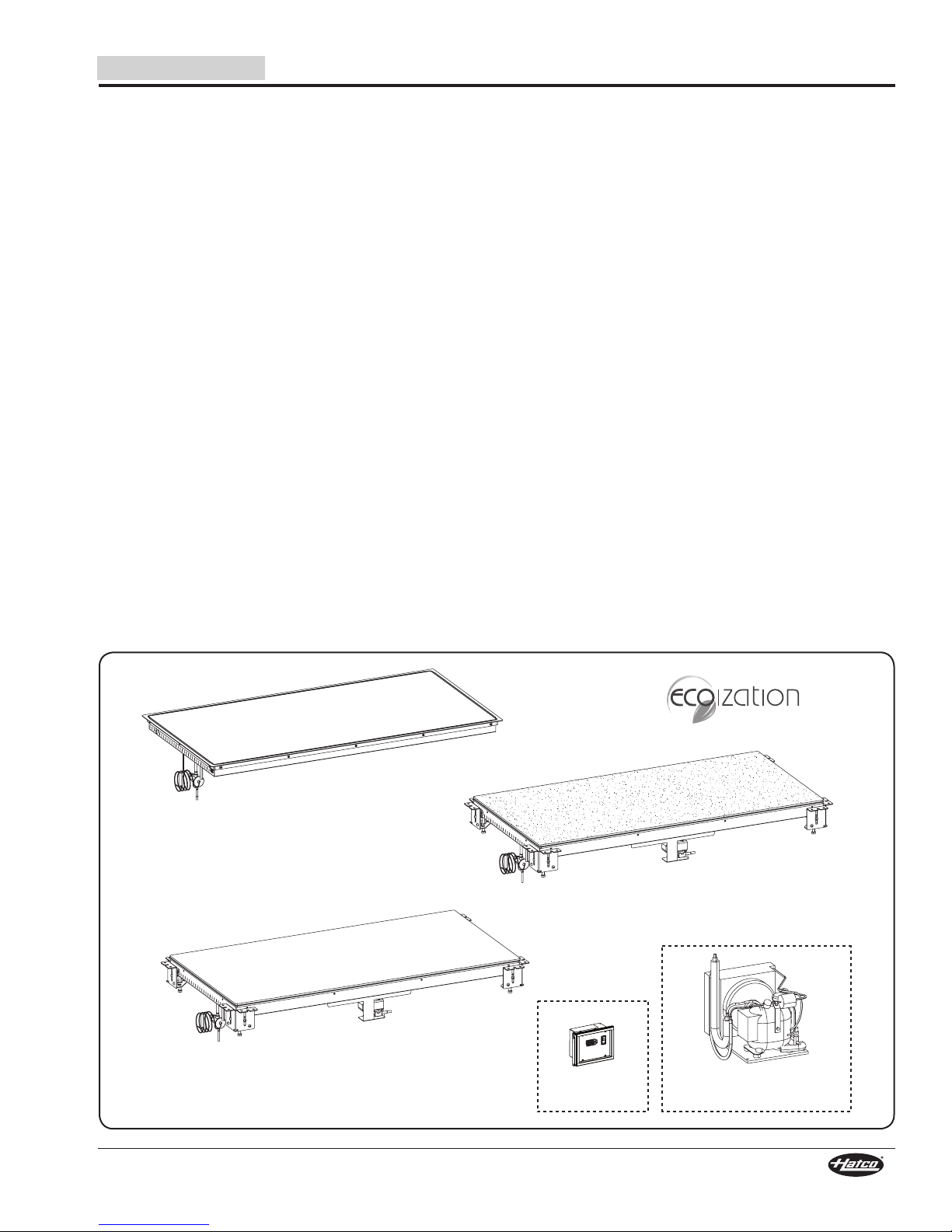
English
Condensing Unit
(CSBFR, CSSBR, CSSBFR,
and CSUR Models only)
CSBFR-48-S/CSBFX-48-S
CSUR-48-S/CSUX-48-S
CSSBR-4818/CSSBX-4818
Control Panel
(All Models)
MODEL DESCRIPTION
All Models
Hatco Remote Cold Shelves Built-In are reliable and versatile.
Each unit has an insulated, stainless steel and aluminized
steel housing. A copper evaporator coil wound under the entire
hardcoat aluminum or stone surface provides even chilling
from edge to edge. Hatco Remote Cold Shelves are designed,
manufactured, and tested to maintain safe food holding
temperatures.
Controls for the Cold Shelves Built-In are housed in a single,
remote-mountable control enclosure. They include a Power I/O
(on/off) Switch and a digital temperature controller. The control
enclosure is field connected to the shelf and the condensing
unit (remote condensing unit models only).
Depending on the model, Cold Shelves Built-In are designed to
be mounted to the top side, bottom side, or underneath various
types of countertop material including stainless steel, wood,
Corian, and Swanstone.
The ecoization logo identifies products designed to reflect
Hatco’s commitment to improving, protecting, and preserving
the global environment. Hatco Remote Cold Shelves Built-In
qualify for the ecoization logo through the use of eco-friendly
insulation as well as a highly efficient condensing unit.
NOTE: Stone surfaces are a simulated stone solid surface.
CSBFR Models
CSBFR models have a hardcoat aluminum surface and are
top mounted.
CSSBR and CSSBFR Models
CSSBR and CSSBFR models have a decorative stone surface
and are bottom mounted.
CSUR Models
CSUR models have an aluminum surface and are mounted
directly against the underside of a granite or quartz countertop
(no cutout required). Cooling transfers through the countertop
to the top side for a true, seamless installation.
NOTE: For CSBFR, CSSBR, CSSBFR, and CSUR models,
all plumbing and electrical connections between the
components as well as to the electrical supply are the
responsibility of the end user and a qualified installer.
CSBFX Models
CSBFX models have a hardcoat aluminum surface and are top
mounted. They are not supplied with a condensing unit.
CSSBX and CSSBFX Models
CSSBX and CSSBFX models have a decorative stone
surface and are bottom mounted. They are not supplied with a
condensing unit.
CSUX Models
CSUX models are similar to CSUR models, but are not supplied
with a condensing unit.
NOTE: CSBFX, CSSBX, CSSBFX, and CSUX models must
be connected to an end user-supplied condensing unit.
All plumbing and electrical connections between the
components as well as to the electrical supply are the
responsibility of the end user and a qualified installer.
Form No. CSRM-0817
5
Page 6
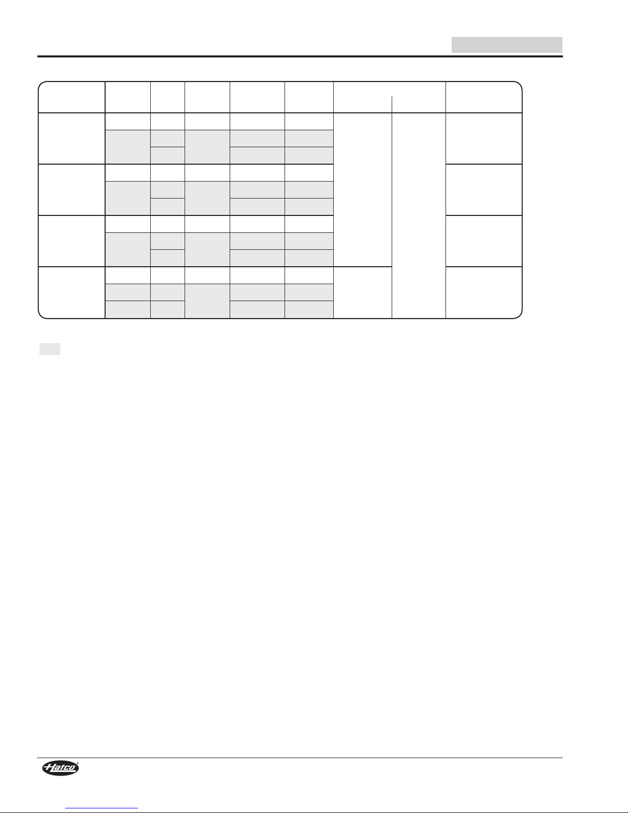
SPECIFICATIONS
Electrical Rating Chart — CSSBR Models
English
Comp.
Model
CSSBR-2418 1/4 hp 60 120 804 6.7
CSSBR-3018 1/4 hp 60 120 804 6.7
CSSBR-3618 1/4 hp 60 120 804 6.7
CSSBR-4818 1/3 hp 60 120 1044 8.7
NOTE: Shipping weights include packaging and are estimated.
The shaded areas contain electrical information for
International models only.
Size Hertz Volts Watts Amps
1/3 hp
1/3 hp
1/3 hp
1/3 hp 60 686-816 3.1-3.4
50
220-240
60 686-816 3.1-3.4
50
220-240
60 686-816 3.1-3.4
50
220-240
60 686-816 3.1-3.4
220-240
616-744 2.8-3.1
616-744 2.8-3.1
616-744 2.8-3.1
807-960 3.7-4.0
Design Pressure
373 psig
(25.72 bar)
174 psig
(12 bar)
423 psig
(29.16 bar)
Shipping
WeightHigh Side Low Side
105 lbs. (48 kg)
131 lbs. (59 kg)
149 lbs. (68 kg)
171 lbs. (78 kg)3/8 hp 50
6
Form No. CSRM-0817
Page 7

English
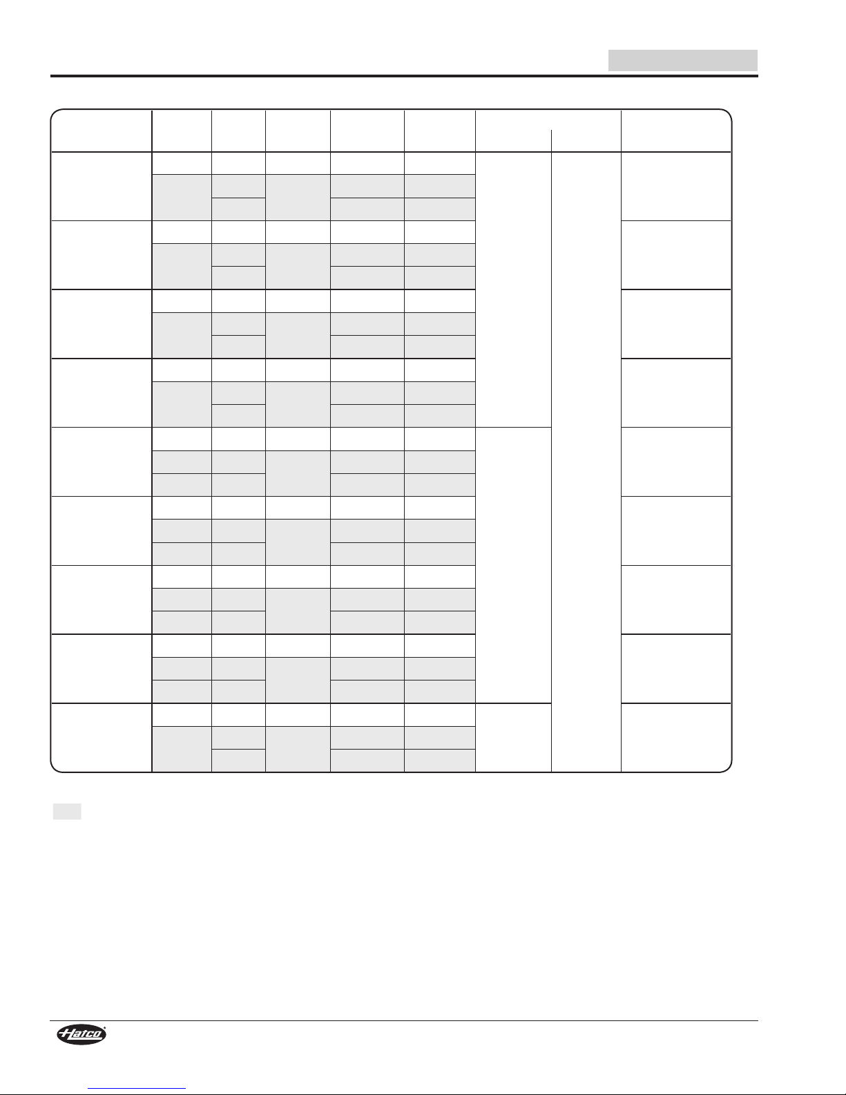
Electrical Rating Chart — CSBFR Models
SPECIFICATIONS
Comp.
Model
CSBFR-24-F 1/4 hp 60 120 804 6.7
CSBFR-24-I 1/4 hp 60 120 804 6.7
CSBFR-24-S 1/4 hp 60 120 804 6.7
CSBFR-36-F 1/4 hp 60 120 804 6.7
CSBFR-36-I 1/3 hp 60 120 1044 8.7
CSBFR-36-S 1/3 hp 60 120 1044 8.7
CSBFR-48-F 1/3 hp 60 120 1044 8.7
CSBFR-48-I 1/3 hp 60 120 1044 8.7
CSBFR-48-S 1/2 hp 60 120 1380 11.5
Size Hertz Volts Watts Amps
1/3 hp
1/3 hp
1/3 hp
1/3 hp
1/3 hp 60 686-816 3.1-3.4
3/8 hp 50
1/3 hp 60 686-816 3.1-3.4
1/3 hp 60 686-816 3.1-3.4
1/3 hp 60 686-816 3.1-3.4
1/2 hp
50
220-240
60 686-816 3.1-3.4
50
220-240
60 686-816 3.1-3.4
50
220-240
60 686-816 3.1-3.4
50
220-240
60 686-816 3.1-3.4
220-240
220-240
220-240
220-240
50 220-240 1190-1416 5.4-5.9
60 220-240 1210-1440 5.5-6.0
616-744 2.8-3.1
616-744 2.8-3.1
616-744 2.8-3.1
616-744 2.8-3.1
807-960 3.7-4.0
807-960 3.7-4.0
807-960 3.7-4.0
807-960 3.7-4.0
Design Pressure
373 psig
(25.72 bar)
174 psig
(12 bar)
423 psig
(29.16 bar)
331 psig
(22.82 bar)
Shipping
WeightHigh Side Low Side
96 lbs. (44 kg)
109 lbs. (49 kg)
124 lbs. (56 kg)
121 lbs. (55 kg)
137 lbs. (62 kg)3/8 hp 50
163 lbs. (74 kg)
144 lbs. (65 kg)3/8 hp 50
173 lbs. (78 kg)3/8 hp 50
176 lbs. (80 kg)
Form No. CSRM-0817
7
Page 8
SPECIFICATIONS
Electrical Rating Chart — CSSBFR Models
English
Comp.
Model
CSSBFR-24-F 1/4 hp 60 120 804 6.7
CSSBFR-24-I 1/4 hp 60 120 804 6.7
CSSBFR-24-S 1/4 hp 60 120 804 6.7
CSSBFR-36-F 1/4 hp 60 120 804 6.7
CSSBFR-36-I 1/3 hp 60 120 1044 8.7
CSSBFR-36-S 1/3 hp 60 120 1044 8.7
CSSBFR-48-F 1/3 hp 60 120 1044 8.7
CSSBFR-48-I 1/3 hp 60 120 1044 8.7
CSSBFR-48-S 1/2 hp 60 120 1380 11.5
Size Hertz Volts Watts Amps
1/3 hp
1/3 hp
1/3 hp
1/3 hp
1/3 hp 60 686-816 3.1-3.4
1/3 hp 60 686-816 3.1-3.4
1/3 hp 60 686-816 3.1-3.4
1/3 hp 60 686-816 3.1-3.4
1/2 hp
50
220-240
60 686-816 3.1-3.4
50
220-240
60 686-816 3.1-3.4
50
220-240
60 686-816 3.1-3.4
50
220-240
60 686-816 3.1-3.4
220-240
220-240
220-240
220-240
50
220-240
60 1210-1440 5.5-6.0
616-744 2.8-3.1
616-744 2.8-3.1
616-744 2.8-3.1
616-744 2.8-3.1
807-960 3.7-4.0
807-960 3.7-4.0
807-960 3.7-4.0
807-960 3.7-4.0
1190-1416 5.4-5.9
Design Pressure
373 psig
(25.72 bar)
174 psig
(12 bar)
423 psig
(29.16 bar)
331 psig
(22.82 bar)
Shipping
WeightHigh Side Low Side
101 lbs. (46 kg)
115 lbs. (52 kg)
131 lbs. (59 kg)
130 lbs. (59 kg)
146 lbs. (66 kg)3/8 hp 50
173 lbs. (78 kg)3/8 hp 50
153 lbs. (69 kg)3/8 hp 50
187 lbs. (85 kg)3/8 hp 50
195 lbs. (89 kg)
NOTE: Shipping weights include packaging and are estimated.
The shaded areas contain electrical information for
International models only.
8
Form No. CSRM-0817
Page 9
English
Electrical Rating Chart — CSUR Models
SPECIFICATIONS
Comp.
Model
CSUR-24-F 1/4 hp 60 120 804 6.7
CSUR-24-I 1/4 hp 60 120 804 6.7
CSUR-24-S 1/4 hp 60 120 804 6.7
CSUR-36-F 1/4 hp 60 120 804 6.7
CSUR-36-I 1/3 hp 60 120 1044 8.7
CSUR-36-S 1/3 hp 60 120 1044 8.7
CSUR-48-F 1/3 hp 60 120 1044 8.7
CSUR-48-I 1/3 hp 60 120 1044 8.7
CSUR-48-S 1/2 hp 60 120 1380 11.5
Size Hertz Volts Watts Amps
1/3 hp
1/3 hp
1/3 hp
1/3 hp
1/3 hp 60 686-816 3.1-3.4
1/3 hp 60 686-816 3.1-3.4
1/3 hp 60 686-816 3.1-3.4
1/3 hp 60 686-816 3.1-3.4
1/2 hp
50
220-240
60 686-816 3.1-3.4
50
220-240
60 686-816 3.1-3.4
50
220-240
60 686-816 3.1-3.4
50
220-240
60 686-816 3.1-3.4
220-240
220-240
220-240
220-240
50
220-240
60 1210-1440 5.5-6.0
616-744 2.8-3.1
616-744 2.8-3.1
616-744 2.8-3.1
616-744 2.8-3.1
807-960 3.7-4.0
807-960 3.7-4.0
807-960 3.7-4.0
807-960 3.7-4.0
1190-1416 5.4-5.9
Design Pressure
373 psig
(25.72 bar)
174 psig
(12 bar)
423 psig
(29.16 bar)
331 psig
(22.82 bar)
Shipping
WeightHigh Side Low Side
101 lbs. (46 kg)
115 lbs. (52 kg)
131 lbs. (59 kg)
130 lbs. (59 kg)
146 lbs. (66 kg)3/8 hp 50
173 lbs. (78 kg)3/8 hp 50
153 lbs. (69 kg)3/8 hp 50
187 lbs. (85 kg)3/8 hp 50
195 lbs. (89 kg)
Electrical Rating Chart — Solenoid Valve
(CSBFX, CSSBX, CSSBFX, and CSUX Models)
Volts Hertz Watts Amps
120 60 12 0.1
50 17 0.1
220–240
60 12 0.1
Refrigerant Information
All Hatco Remote Cold Shelves use R404A refrigerant in the condensing unit.
Form No. CSRM-0817
9
Page 10
SPECIFICATIONS
E
D
Top View
A
C
B
Front View Side View
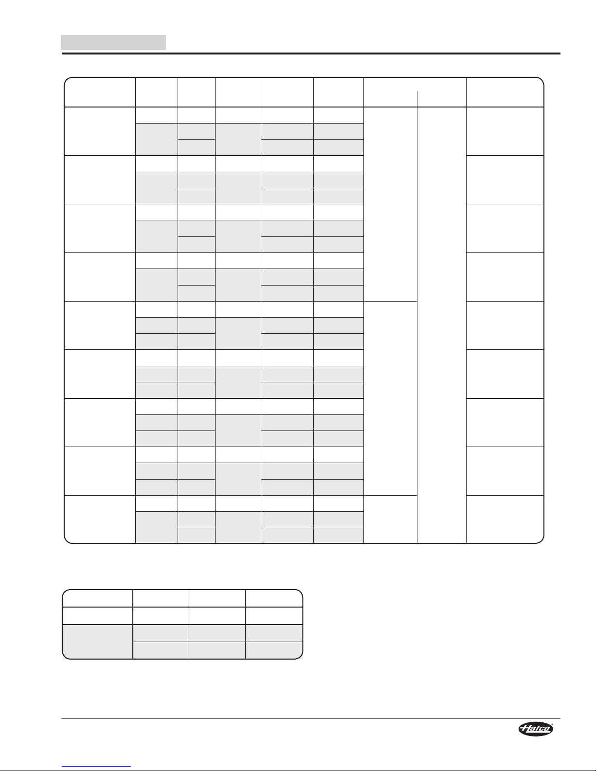
Dimensions — CSBFR and CSBFX Models
English
Model
CSBFR-24-F
CSBFX-24-F
CSBFR-24-I
CSBFX-24-I
CSBFR-24-S
CSBFX-24-S
CSBFR-36-F
CSBFX-36-F
CSBFR-36-I
CSBFX-36-I
CSBFR-36-S
CSBFX-36-S
CSBFR-48-F
CSBFX-48-F
CSBFR-48-I
CSBFX-48-I
CSBFR-48-S
CSBFX-48-S
Width
(A)
25-1/2″
(648 mm)
37-1/2″
(953 mm)
49-1/2″
(1257 mm)
Depth
(B)
17″
(432 mm)
21″
(533 mm)
25-1/2″
(648 mm)
17″
(432 mm)
21″
(533 mm)
25-1/2″
(648 mm)
17″
(432 mm)
21″
(533 mm)
25-1/2″
(648 mm)
Height
(C)
2-1/8″
(53 mm)
Cooled
Width (D)
24″
(610 mm)
36″
(914 mm)
48″
(1219 mm)
Cooled
Depth (E)
15-1/2″
(394 mm)
19-1/2″
(495 mm)
24″
(610 mm)
15-1/2″
(394 mm)
19-1/2″
(495 mm)
24″
(610 mm)
15-1/2″
(394 mm)
19-1/2″
(495 mm)
24″
(610 mm)
10
Form No. CSRM-0817
Page 11
English
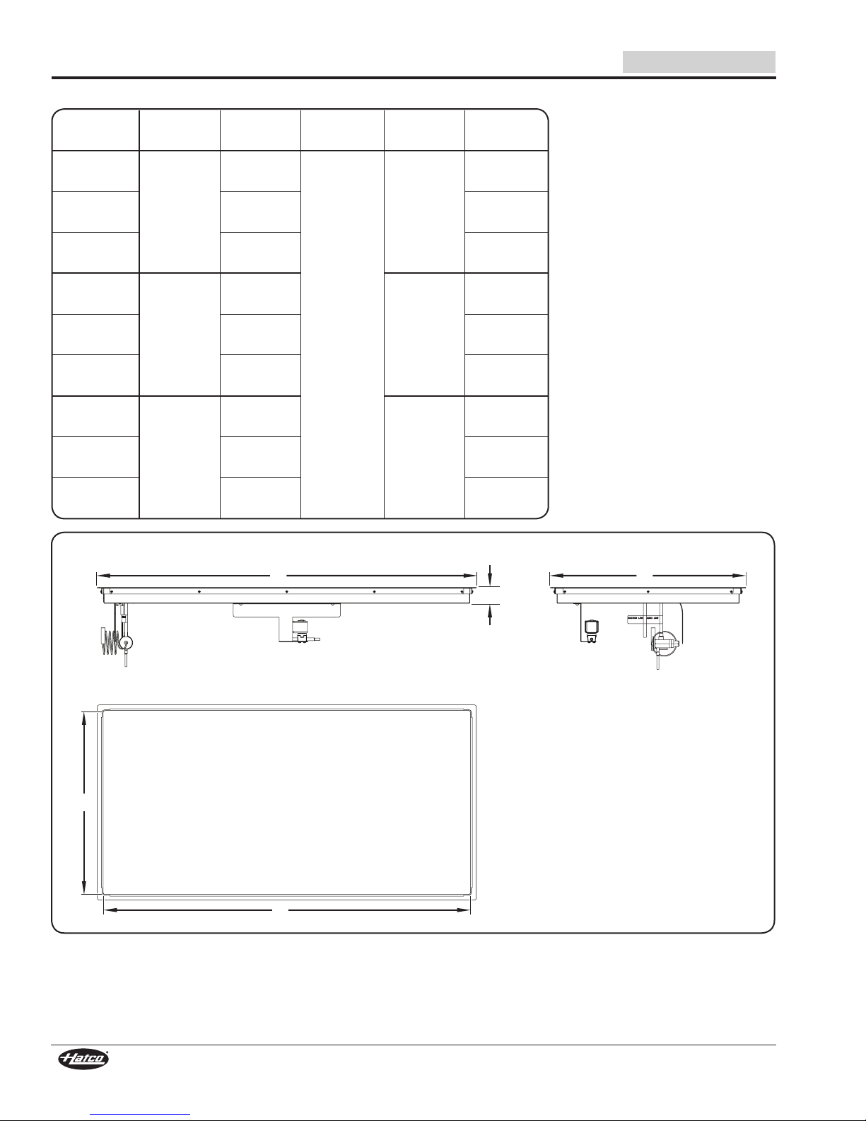
Front View Side View
Top View
E
D
A
C
B
Dimensions — CSSBR, CSSBFR, CSSBX, CSSBFX Models
Model Width (A) Depth (B) Height (C) Cooled Width (D) Cooled Depth (E)
CSSBR-2418
CSSBX-2418
CSSBR-3018
CSSBX-3018
CSSBR-3618
CSSBX-3618
CSSBR-4818
CSSBX-4818
CSSBFR-24-F
CSSBFX-24-F
27″
(686 mm)
33″
(838 mm)
39″
(991 mm)
51″
(1295 mm)
21″
(533 mm)
18-1/2″
(470 mm)
2-3/8″
(60 mm)
24″
(610 mm)
30″
(762 mm)
36″
(914 mm)
48″
(1219 mm)
SPECIFICATIONS
18″
(457 mm)
15-1/2″
(394 mm)
CSSBFR-24-I
CSSBFX-24-I
CSSBFR-24-S
CSSBFX-24-S
CSSBFR-36-F
CSSBFX-36-F
CSSBFR-36-I
CSSBFX-36-I
CSSBFR-36-S
CSSBFX-36-S
CSSBFR-48-F
CSSBFX-48-F
CSSBFR-48-I
CSSBFX-48-I
CSSBFR-48-S
CSSBFX-48-S
27″
(686 mm)
39″
(991 mm)
51″
(1295 mm)
22-1/2″
(572 mm)
27″
(686 mm)
18-1/2″
(470 mm)
22-1/2″
(572 mm)
27″
(686 mm)
18-1/2″
(470 mm)
22-1/2″
(572 mm)
27″
(686 mm)
2-3/8″
(60 mm)
24″
(610 mm)
36″
(914 mm)
48″
(1219 mm)
19-1/2″
(495 mm)
24″
(610 mm)
15-1/2″
(394 mm)
19-1/2″
(495 mm)
24″
(610 mm)
15-1/2″
(394 mm)
19-1/2″
(495 mm)
24″
(610 mm)
Form No. CSRM-0817
11
Page 12

SPECIFICATIONS
D
A
B
C
4X Ø 10 mm
(0.375″)
Top ViewFront View
Air Flow
Side View
E
F
Dimensions — CSUR and CSUX Models
NOTE: See dimension illustration for CSSBR and CSSBFR models on previous page for reference.
English
Model
CSUR-24-F
CSUX-24-F
CSUR-24-I
CSUX-24-I
CSUR-24-S
CSUX-24-S
CSUR-36-F
CSUX-36-F
CSUR-36-I
CSUX-36-I
CSUR-36-S
CSUX-36-S
CSUR-48-F
CSUX-48-F
CSUR-48-I
CSUX-48-I
CSUR-48-S
CSUX-48-S
Width
(A)
27-5/16″
(694 mm)
39-5/16″
(998 mm)
51-3/16″
(1295 mm)
Depth
(B)
18-13/16″
(478 mm)
22-13/16″
(579 mm)
27-5/16″
(694 mm)
18-13/16″
(478 mm)
22-13/16″
(579 mm)
27-5/16″
(694 mm)
18-13/16″
(478 mm)
22-13/16″
(579 mm)
27-5/16″
(694 mm)
Height
(C)
2-1/8″
(53 mm)
Cooled
Width (D)
24″
(610 mm)
36″
(914 mm)
48″
(1219 mm)
Cooled
Depth (E)
15-1/2″
(394 mm)
19-1/2″
(495 mm)
24″
(610 mm)
15-1/2″
(394 mm)
19-1/2″
(495 mm)
24″
(610 mm)
15-1/2″
(394 mm)
19-1/2″
(495 mm)
24″
(610 mm)
Dimensions — Condensing Unit
Compressor
Size
1/4 hp
1/3 hp
3/8 hp
1/2 hp
Base
Width (A)
13-5/8″
(346 mm)
16″
(406 mm)
17-3/8″
(441 mm)
Base
Depth (B)
10-3/4″
(273 mm)
12-1/8″
(307 mm)
12-1/8″
(307 mm)
Overall
Depth (C)
(305 mm)
13-1/8″
(334 mm)
13-1/8″
(334 mm)
12″
Mounting
Height
(D)
11-3/8″
(289 mm)
11-3/8″
(289 mm)
11-13/16″
(300 mm)
Hole Width
(E)
6-1/2″
(165 mm)
9-1/4″
(235 mm)
10″
(254 mm)
Mounting
Hole Depth
(F)
9-9/16″
(242 mm)
11-1/4″
(286 mm)
11-1/4″
(286 mm)
12
Form No. CSRM-0817
Page 13

English
WARNING
INSTALLATION
General
Remote Cold Shelves Built-In are shipped from the factory as
components that require installation and connection. Use the
following information and procedures to prepare the unit and
the installation site.
NOTE: Make sure the installation location provides enough
room for the condensing unit and the remote mounted
control enclosure.
ELECTRIC SHOCK HAZARD:
• Plug unit into a properly grounded electrical receptacle
of the correct voltage, size, and plug configuration. If
plug and receptacle do not match, contact a qualified
electrician to determine and install proper voltage and
size electrical receptacle.
• Unit is not weatherproof. Locate unit indoors.
• Remote control enclosure must be mounted on vertical
wall and installed in vertical position. Mounting remote
control enclosure in horizontal position may result in
collection of liquids and lead to electric shock.
FIRE HAZARD: Install condensing unit with a minimum
of2″ (51mm)of spacebetweenall sidesofunit andany
combustible surfaces.
CAUTION
Locate the unit at the proper counter height in an area that is
convenient for use. The location should be level and strong
enough to support the weight of the unit and contents.
NOTICE
Transport and install unit in upright position only. Failure
to do so may result in damage to refrigeration system.
This unit is designed for use in environments where ambient
temperature is between 65°F (18°C) and 86°F (30°C).
When shipped during cold weather months, store unit
for at least 10 hours in an environment where ambient
temperature is between 65°F (18°C) and 86°F (30°C) to
prevent compressor and/or refrigerant line damage. If unit
is turned on and there is excessive noise and vibration, turn
off immediately and allow additional warmup time.
Provide louvered or grill-style openings with a minimum
size of 12″ x 12″/144 square inches (31 x 31 cm/
961 square cm) in the cabinetry in front of and behind the
condensing unit for proper ventilation. Failure to provide
adequate air flow through the condensing unit may cause
unit failure and will void the unit warranty.
Do not recirculate exhaust air inside cabinet when multiple
condensing units are installed together. Intake air should
enter from outside of cabinet.
Do not locate unit in area with excessive air movement
around unit. Avoid areas that may be subject to active air
movements or currents (i.e., near exhaust fans/hoods, air
conditioning ducts, and exterior doors).
Do not locate unit in an area subject to excessive
temperatures or grease from grills, fryers, etc. Excessive
temperatures could cause damage to the unit.
Damage to any countertop material caused by heat or cold
generated from Hatco equipment is not covered under
the Hatco warranty. Contact manufacturer of countertop
material for application information.
Form No. CSRM-0817
All cold shelves are shipped in a shipping frame for protection
and stability. Keep the unit in the shipping frame until the unit
and the installation site are completely prepared for the unit to
be installed.
Survey the installation site. Take into account the need for
louvered or grill-style openings in the cabinetry to provide
proper ventilation for the condensing unit as well as access to
the control panel. One of these ventilation openings must be in
front of the condensing coils with the other on the opposite side.
If multiple condensing units are installed in the same counter,
each unit should intake cool air and expel hot air.
1. Remove all external packaging from the unit.
NOTE: To prevent delay in obtaining warranty coverage,
complete online warranty registration. See the
IMPORTANT OWNER INFORMATION section for
details.
2. Remove tape, protective packaging, and literature from all
surfaces of the unit.
Preparing the Installation Site
1. Prepare the appropriate opening and mounting bolt holes
in the countertop for the unit being installed.
• For top mounted CSBFR and CSBFX models, refer to
“Countertop Cutout Dimensions — Top Mounted Units,”
in this section.
• For bottom mounted CSSBR, CSSBFR, CSSBX, and
CSSBFX models, refer to “Countertop Cutout and
Mounting Bolt Dimensions — Bottom Mounted Units,”
in this section.
• For underside, surface mounted CSUR and CSUX
models, refer to “Mounting Bolt Dimensions—CSUR
and CSUX Models” in this section. Make sure the
countertop is a solid surface material with good heat
transfer characteristics, such as stainless steel, granite,
quartz, Corian®, etc... The thickness of the countertop
should be 1-3/16″ (30 mm) or less.
NOTE: The performance of each type of solid surface material
will vary dependant upon the material’s characteristics.
2. Cut and drill the appropriate holes in the vertical surface
where the control enclosure will be installed. Refer to the
“Installing the Control Enclosure Remotely” procedure for
cutout dimensions.
• The installation depth required for the control enclosure
is 8-1/2″ (216 mm).
3. Make structural modifications or add bracing underneath
the countertop to ensure the countertop will support the
weight of the unit and its contents.
4. Install the unit. Refer to the appropriate procedure in this
section for the model being installed.
13
Page 14
INSTALLATION
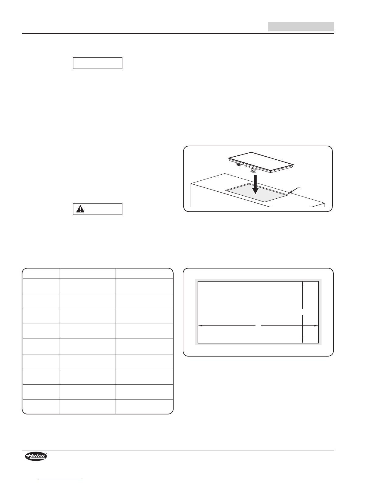
B
A
CAUTION
Countertop
Cutout
English
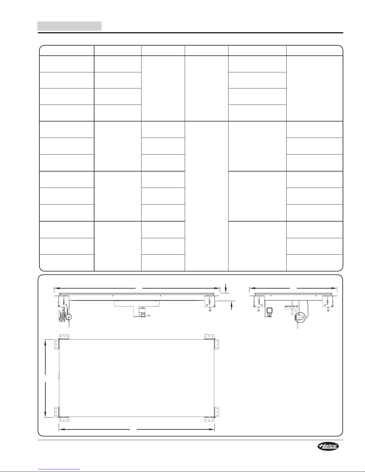
Installing a Top Mounted Unit (CSBFR and
CSBFX Models)
NOTICE
Use caution and avoid hitting condensing unit hoses/lines
when installing unit. Damage caused during installation is
not covered under warranty.
1. Apply a bead of National Sanitation Foundation (NSF)approved silicone sealant on the top edge of the countertop
cutout and the underside of the trim mounting ring. The
sealant must be rated for use at temperatures between
-10°F (-23°C) and 250°F (121°C).
2. Lift the cold shelf out of the shipping frame and carefully
lower it into the countertop cutout. This step requires two or
more people.
NOTE: If excessive condensation appears underneath the
countertop during operation, apply polyurethane-based
foam sealant in the gap between the underside of the
countertop and the shelf.
3. Install the control panel in the desired location.
• The control enclosure can be installed remotely within
6′ (1829 mm) of the shelf. Refer to the “Installing the
Control Enclosure Remotely” procedure in this section.
DO NOT tip unit/mounting surface after final installation.
Unit is free-floating and could fall out if tipped—for
permanent, horizontal installations only.
4. For CSBFR models, install the condensing unit in the
desired location. Refer to the SPECIFICATION section for
installation dimensions.
• Make sure the installation site provides a level, stable
surface for mounting the condensing unit.
• Make sure the installation site offers continuous air flow
ventilation to the condensing unit.
• Make sure there is a minimum of 6″ (152 mm) of space
between all sides of the condensing unit and any
combustible surface.
5. Have qualified installers perform the “Connecting the
Components” procedure in this section.
6. Clean the cold surface thoroughly in preparation for initial
operation. Refer to the MAINTENANCE section for proper
cleaning procedures.
Installing a CSBFR Model Cold Shelf
Countertop Cutout Dimensions — Top Mounted Units
Model Width (A) Depth (B)
CSBFR-24-F
CSBFX-24-F
CSBFR-24-I
CSBFX-24-I
CSBFR-24-S
CSBFX-24-S
CSBFR-36-F
CSBFX-36-F
CSBFR-36-I
CSBFX-36-I
CSBFR-36-S
CSBFX-36-S
CSBFR-48-F
CSBFX-48-F
CSBFR-48-I
CSBFX-48-I
CSBFR-48-S
CSBFX-48-S
24-5/8″ to 25″
(625 to 635 mm)
24-5/8″ to 25″
(625 to 635 mm)
24-5/8″ to 25″
(625 to 635 mm)
36-5/8″ to 37″
(930 to 940 mm)
36-5/8″ to 37″
(930 to 940 mm)
36-5/8″ to 37″
(930 to 940 mm)
48-5/8″ to 49″
(1234 to 1245 mm)
48-5/8″ to 49″
(1234 to 1245 mm)
48-5/8″ to 49″
(1234 to 1245 mm)
16-1/8″ to 16-1/2″
(409 to 419 mm)
20-1/8″ to 20-1/2″
(511 to 521 mm)
24-5/8″ to 25″
(625 to 635 mm)
16-1/8″ to 16-1/2″
(409 to 419 mm)
20-1/8″ to 20-1/2″
(511 to 521 mm)
24-5/8″ to 25″
(625 to 635 mm)
16-1/8″ to 16-1/2″
(409 to 419 mm)
20-1/8″ to 20-1/2″
(511 to 521 mm)
24-5/8″ to 25″
(625 to 635 mm)
14
Form No. CSRM-0817
Page 15
English
BE F
A
C
D
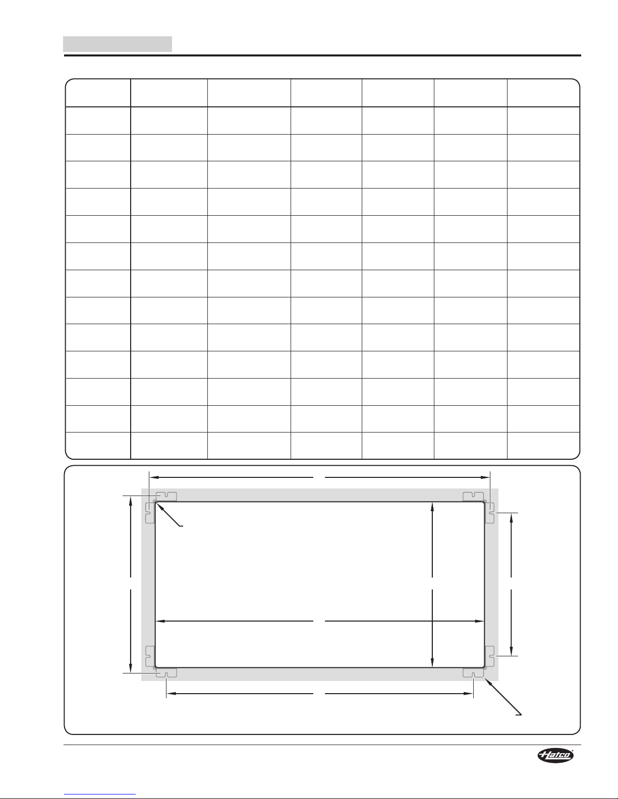
R = 0.375" (9.5 mm) x 4
Mounting brackets shown for hole location reference. Holes must be pre-drilled
on underside of countertop where brackets will be mounted.
INSTALLATION
Countertop Cutout and Mounting Bolt Dimensions — Bottom Mounted Units
Model
CSSBR-2418
CSSBX-2418
CSSBR-3018
CSSBX-3018
CSSBR-3618
CSSBX-3618
CSSBR-4818
CSSBX-4818
CSSBFR-24-F
CSSBFX-24-F
CSSBFR-24-I
CSSBFX-24-I
CSSBFR-24-S
CSSBFX-24-S
CSSBFR-36-F
CSSBFX-36-F
CSSBFR-36-I
CSSBFX-36-I
CSSBFR-36-S
CSSBFX-36-S
CSSBFR-48-F
CSSBFX-48-F
CSSBFR-48-I
CSSBFX-48-I
CSSBFR-48-S
CSSBFX-48-S
Cutout
Width (A)
24-3/8″
(619 mm)
30-3/8″
(772 mm)
36-3/8″
(924 mm)
48-3/8″
(1229 mm)
24-3/8″
(619 mm)
24-3/8″
(619 mm)
24-3/8″
(619 mm)
36-3/8″
(924 mm)
36-3/8″
(924 mm)
36-3/8″
(924 mm)
48-3/8″
(1229 mm)
48-3/8″
(1229 mm)
48-3/8″
(1229 mm)
Cutout
Depth (B)
18-3/8″
(467 mm)
18-3/8″
(467 mm)
18-3/8″
(467 mm)
18-3/8″
(467 mm)
15-7/8″
(403 mm)
19-7/8″
(505 mm)
24-3/8”
(619 mm)
15-7/8″
(403 mm)
19-7/8″
(505 mm)
24-3/8”
(619 mm)
15-7/8″
(403 mm)
19-7/8″
(505 mm)
24-3/8″
(619 mm)
Bolt Hole
Location (C)
26-3/8″
(670 mm)
32-3/8″
(822 mm)
38-3/8″
(974 mm)
50-3/8″
(1279 mm)
26-3/8″
(670 mm)
26-3/8″
(670 mm)
26-3/8″
(670 mm)
38-3/8″
(974 mm)
38-3/8″
(974 mm)
38-3/8″
(974 mm)
50-3/8″
(1279 mm)
50-3/8″
(1279 mm)
50-3/8″
(1279 mm)
Bolt Hole
Location (D)
21″
(533 mm)
27″
(685 mm)
33″
(837 mm)
45″
(1142 mm)
21″
(533 mm)
21″
(533 mm)
21″
(533 mm)
33″
(837 mm)
33″
(837 mm)
33″
(837 mm)
45″
(1142 mm)
45″
(1142 mm)
45″
(1142 mm)
Bolt Hole
Location (E)
20-3/8″
(517 mm)
20-3/8″
(517 mm)
20-3/8″
(517 mm)
20-3/8″
(517 mm)
17-7/8″
(454 mm)
21-7/8″
(555 mm)
26-3/8″
(670 mm)
17-7/8″
(454 mm)
21-7/8″
(555 mm)
26-3/8″
(670 mm)
17-7/8″
(454 mm)
21-7/8″
(555 mm)
26-3/8″
(670 mm)
Bolt Hole
Location (F)
15″
(380 mm)
15″
(380 mm)
15″
(380 mm)
15″
(380 mm)
12-1/2″
(317 mm)
16-1/2″
(418 mm)
21″
(533 mm)
12-1/2″
(317 mm)
16-1/2″
(418 mm)
21″
(533 mm)
12-1/2″
(317 mm)
16-1/2″
(418 mm)
21″
(533 mm)
Form No. CSRM-0817
15
Page 16
Bottom
of unit.
Washer
Shipping
Screw
Mounting
Bracket
A
ssembly
Shipping
Bracket
Shipping
Screw
Countertop
Cutout
Accessory
Gasket
Inside surface of
mounting bracket
assembly flush with
inside of cutout.
Lock Nut
Leveling Bolt
INSTALLATION
English
Installing a Bottom Mounted Unit (CSSBR,
CSSBFR, CSSBX, and CSSBFX Models)
NOTICE
Use caution and avoid hitting condensing unit hoses/lines
when installing unit. Damage caused during installation is
not covered under warranty.
NOTE: Accessory Installation Kits that include a self-
adhesive gasket for caulk backing as well as colored
silicone sealant are available. Refer to the OPTIONS
AND ACCESSORIES section.
1. Remove the mounting
bracket assembly from
each corner of the cold
shelf. To remove:
a. Remove the two shipping
screws and washers that
attach each mounting
bracket assembly to the
bottom of the unit.
b. Carefully lift the cold
shelf above the shipping
frame, and rotate it far enough to allow the unit to be set
back down on top of the frame (the mounting brackets
will stay on the frame or fall out the bottom). This step
requires two or more people, depending on the unit.
c. Remove the mounting bracket assemblies from the
frame, if necessary.
2. On each mounting bracket
assembly, remove the
shipping screws and the
triangular shipping bracket
that was used to attach the
mounting bracket assembly
to the bottom of the cold
shelf, and discard.
3. Attach a mounting bracket
assembly to the underside
of the prepared countertop
at each corner of the cutout.
a. Align the u-shaped mounting holes on the mounting
bracket with the two pre-drilled mounting holes on the
underside of the countertop. The inside surface of the
mounting bracket should be vertically flush with the inner
surface of the countertop cutout.
b. Insert appropriate fasteners through the mounting
bracket and into appropriate anchoring devices in the
mounting holes on the underside of the countertop.
Tighten securely.
4. Install the accessory, self-adhesive gasket around the
inner, vertical surface of the countertop cutout, if available.
• The gasket should be positioned 1/4″ (6 mm) below the
top surface of the countertop.
NOTE: If the accessory, self-adhesive gasket is not available,
provide a caulk backing around the inner, vertical
surface of the countertop cutout 1/4″ (6 mm) below
the top surface of the countertop. This will prevent the
silicone sealant applied later in this procedure from
falling through the gap between the countertop and the
cold shelf.
Installing a CSSBFR Model Cold Shelf
16
Form No. CSRM-0817
Page 17
English
Seal this gap with foam sealant
underneath the entire unit.
Bottom
of unit.
Washer
Shipping
Screw
Mounting
Bracket
A
ssembly
Shipping
Bracket
Shipping
Screw
INSTALLATION
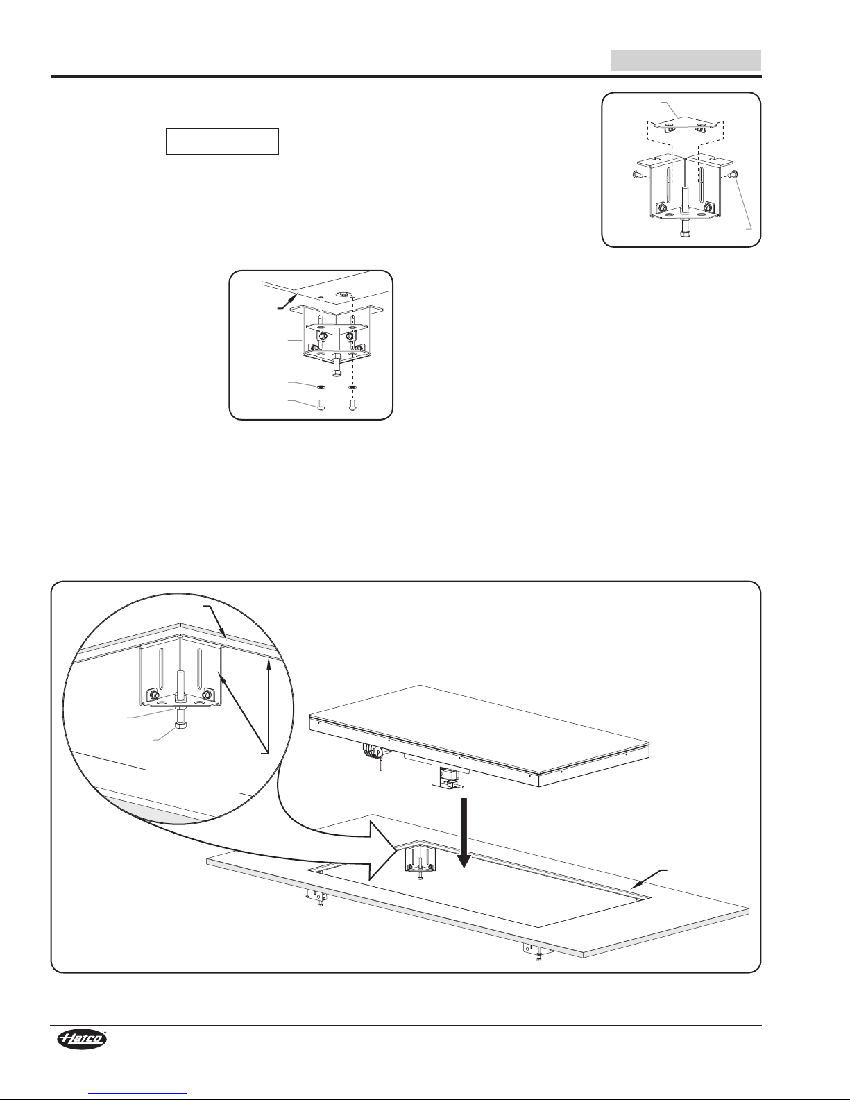
5. Carefully lower the condensing unit followed by the cold
shelf into the countertop cutout. This step requires two or
more people.
• The condensing unit must go into the cutout first and be
fastened to a level, stable surface within 6′ (1829 mm) of
the connections on the bottom of the cold shelf. Refer to
the SPECIFICATIONS section for installation dimensions.
• The cold shelf rests on top of the four leveling bolts,
which are part of the mounting bracket assembly
installed at each corner of the countertop cutout.
6. Adjust the leveling bolts underneath each corner of the unit so
that the shelf is flush or slightly below the countertop surface.
7. Tighten the lock nut on each leveling bolt to secure the position.
8. Apply a bead of NSF-approved silicone sealant in the gap
above the countertop and the cold shelf. To apply a clean,
consistent sealant bead:
a. Make sure the shelf is centered in the countertop cutout.
b. Install masking tape on each side of the gap to define
the edge of the sealant.
c. Carefully apply sealant into the gap.
d. Quickly smooth the sealant surface.
e. Carefully remove the masking tape before the sealant dries.
NOTE: The silicone sealant must be rated for use at temperatures
between -10°F (-23°C) and 250°F (121°C).
9. Apply polyurethane-based foam sealant in the gap
underneath the countertop and the cold shelf.
Foam Sealant Gap
CAUTION
DO NOT tip unit/mounting surface after final installation.
Unit is free-floating and could fall out if tipped—for
permanent, horizontal installations only.
10. Install the control panel in the desired location.
• The control panel can be installed remotely within
6′ (1829 mm) of the shelf. Refer to the “Installing the
Control Enclosure Remotely” procedure in this section.
11. For CSSBR and CSSBFR models, install the condensing
unit in the desired location. Refer to the SPECIFICATION
section for installation dimensions.
• Make sure the installation site offers continuous air flow
ventilation to the condensing unit.
• Make sure there is a minimum of 6″ (152 mm) of space
between all sides of the condensing unit and any
combustible surface.
Form No. CSRM-0817
11. Have qualified installers perform the “Connecting the
Components” procedure in this section.
12. Clean the shelf surface thoroughly in preparation for initial
operation. Refer to the MAINTENANCE section for proper
cleaning procedures.
Installing an Under Mounted Unit
(CSUR and CSUX Models)
CSUR and CSUX models are surface mounted directly against
the underside of a solid surface countertop (no cutout is
required). Cooling transfers through the countertop to the top
side for a true, seamless installation.
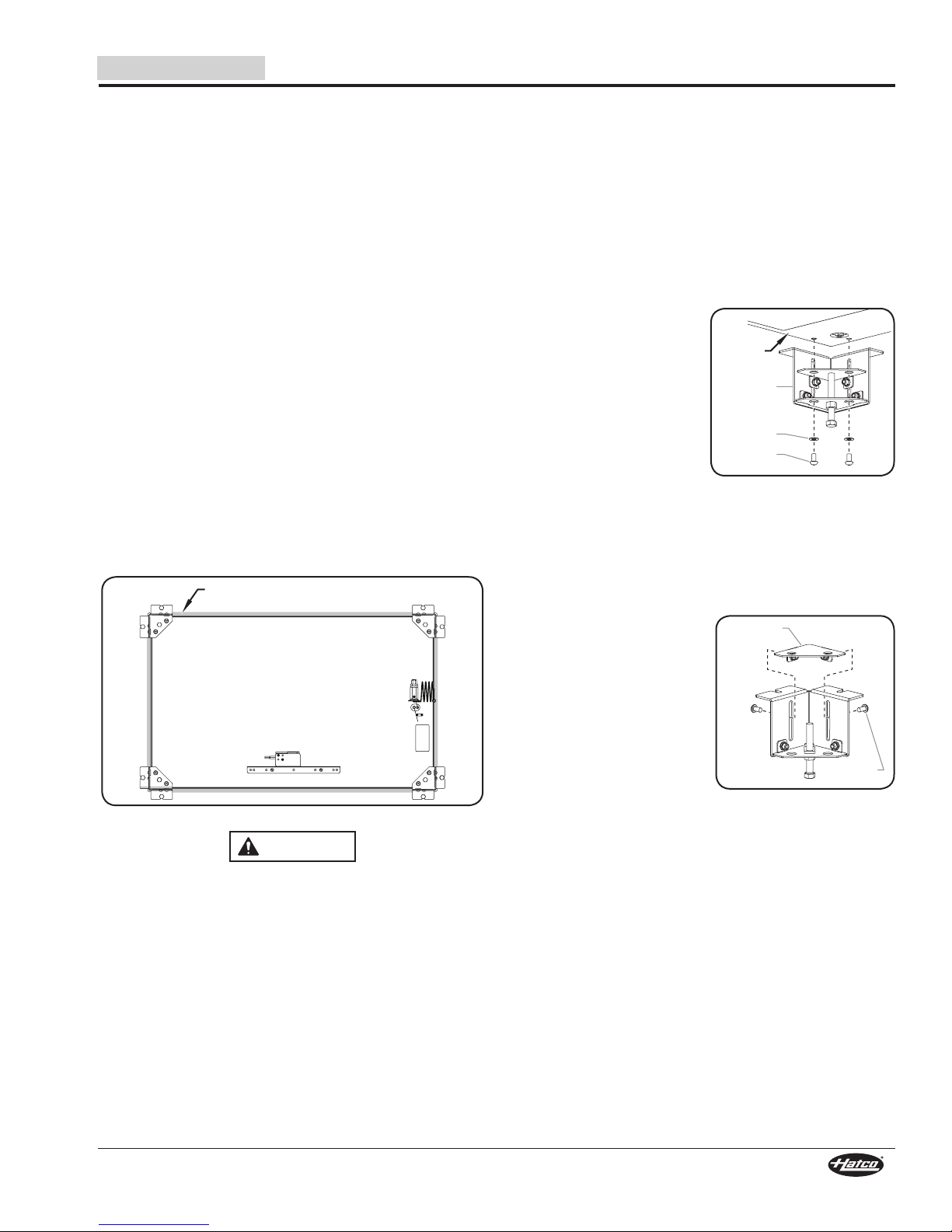
1. Remove the mounting
bracket assembly from
each corner of the cold
shelf. To remove:
a. Remove the two shipping
screws and washers that
attach each mounting
bracket assembly to the
bottom of the unit.
b. Carefully lift the cold
shelf above the wooden shipping frame, and rotate it far
enough to allow the unit to be set back down on top of
the frame (the mounting brackets will stay on the frame
or fall out the bottom). Make sure the flexible tubes from
the condensing unit are not strained or damaged. This
step requires two or more people, depending on the unit.
c. Remove the mounting bracket assemblies from the
frame, if necessary.
2. On each mounting bracket
assembly, remove the
shipping screws and the
triangular shipping bracket
that was used to attach the
mounting bracket assembly
to the bottom of the cold
shelf, and discard.
3. Attach three of the mounting
bracket assemblies to the
underside of the prepared
countertop at the pre-drilled locations. To attach each:
NOTE: See installation illustration on the following page.
a. Align the u-shaped mounting holes on the mounting
bracket with the two pre-drilled mounting holes on the
underside of the countertop. The inside surface of the
mounting bracket should be facing the unit.
b. Insert appropriate fasteners through the mounting
bracket and into appropriate anchoring devices in the
mounting holes on the underside of the countertop.
Tighten securely.
4. Apply a layer of thermal mastic to the top of the shelf using
a 3/16″ (5 mm) notched trowel.
continued...
17
Page 18

INSTALLATION
Seal this gap with foam sealant
underneath the entire unit.
Underside of
Countertop
Mounting
Bracket
Assembly
Lock Nut
Leveling Bolt
English
5. Carefully lift the cold shelf up and into the three mounting
brackets on the underside of the countertop. This step
requires two or more people.
• The cold shelf rests on top of the leveling bolts, which
are part of the mounting bracket assembly installed at
each corner of the cold shelf.
• Slide one end of the cold shelf into the two brackets on
one end while rotating it into the single bracket on the
opposite end.
6. Attach the fourth mounting bracket assembly to the
underside of the countertop at the open corner of the cold
shelf.
7. Adjust the leveling bolts underneath each corner of the
unit so that the shelf is flush against the underside of the
countertop.
8. Tighten the lock nut on each leveling bolt to secure the
position.
9. Apply polyurethane-based foam sealant in the gap
between the countertop and the cold shelf.
10. Install the control panel in the desired location.
• The control panel can be installed remotely within
6′ (1829 mm) of the shelf. Refer to the “Installing the
Control Panel Remotely” procedure in this section.
11. For CSUR models, install the condensing unit in the
desired location. Refer to the SPECIFICATION section for
installation dimensions.
• Make sure the installation site provides a level, stable
surface for mounting the condensing unit.
• Make sure the installation site offers continuous air flow
ventilation to the condensing unit.
• Make sure there is a minimum of 6″ (152 mm) of space
between all sides of the condensing unit and any
combustible surface.
12. Have qualified installers perform the “Connecting the
Components” procedure in this section.
Foam Sealant Gap
Installing a CSUR Model Cold Shelf
18
Form No. CSRM-0817
Page 19

English
C D
A
B
Mounting brackets shown for hole location reference. Holes must be pre-drilled
on underside of countertop where brackets will be mounted.
Unit Outline
Mounting Bolt Dimensions — CSUR and CSUX Models
INSTALLATION
Model
CSUR-24-F
CSUX-24-F
CSUR-24-I
CSUX-24-I
CSUR-24-S
CSUX-24-S
CSUR-36-F
CSUX-36-F
CSUR-36-I
CSUX-36-I
CSUR-36-S
CSUX-36-S
CSUR-48-F
CSUX-48-F
CSUR-48-I
CSUX-48-I
CSUR-48-S
CSUX-48-S
Bolt Hole
Location (A)
26-11/16″
(677 mm)
26-11/16″
(677 mm)
26-11/16″
(677 mm)
38-11/16″
(982 mm)
38-11/16″
(982 mm)
38-11/16″
(982 mm)
50-11/16″
(1287 mm)
50-11/16″
(1287 mm)
50-11/16″
(1287 mm)
Bolt Hole
Location (B)
21-5/16″
(541 mm)
21-5/16″
(541 mm)
21-5/16″
(541 mm)
33-5/16″
(845 mm)
33-5/16″
(845 mm)
33-5/16″
(845 mm)
45-5/16″
(1150 mm)
45-5/16″
(1150 mm)
45-5/16″
(1150 mm)
Bolt Hole
Location (C)
18-3/16″
(462 mm)
22-3/16″
(563 mm)
26-11/16″
(677 mm)
18-3/16″
(462 mm)
22-3/16″
(563 mm)
26-11/16″
(677 mm)
18-3/16″
(462 mm)
22-3/16″
(563 mm)
26-11/16″
(677 mm)
Bolt Hole
Location (D)
12-13/16″
(325 mm)
16-13/16″
(426 mm)
21-5/16″
(541 mm)
12-13/16″
(325 mm)
16-13/16″
(426 mm)
21-5/16″
(541 mm)
12-13/16″
(325 mm)
16-13/16″
(426 mm)
21-5/16″
(541 mm)
Form No. CSRM-0817
19
Page 20

Liquid Connection
(1/4″ O.D. tube)
Condensing
Unit
TXV Valve
Suction Connection
(3/8″ O.D. tube)
TXV Bulb
Shel
f
Shelf
Suction Connection
(3/8″ O.D. tube)
TXV Valve
Solenoid
Valve
To Condensing
Unit
From
Condensing
Unit
Power Input
Power Output
(to condensing unit on
“R” Models or solenoid
valve on “X” Models)
Temperature Probe
Wire Inlet
Terminal Blocks
Digital Temperature
Controller
Access Cover
INSTALLATION
Connecting the Components
Use the following procedure as a guideline for making
the connections between the components of the remote
refrigerated system. These connections must be made by
trained and qualified installers and must comply with all local
plumbing and electrical codes. Refer to the SPECIFICATIONS
section and the wiring diagram included with the unit for details
regarding the plumbing and electrical connections.
1. Connect the liquid and suction refrigerant lines between
the condensing unit, the TXV valve, and the refrigerated
evaporator coil. Refer to the appropriate illustration below
and the SPECIFICATIONS section for connection details.
NOTE: The maximum refrigerant line length between the
condensing unit and the evaporator coil is 50 feet (15 m).
NOTE: For refrigerant line connections, use a self-fluxing
brazing compound (example = Sil-Fos 5®) at a brazing
temperature range of 1300–1500°F (704–816°C).
English
Remote Refrigerant Connections
(CSUX, CSBFX, CSSBX, CSSBFX Models)
2. Have a qualified electrician make the appropriate electrical
connections to the control panel. Refer to the wiring
diagram for details.
For CSUR, CSBFR, CSSBR, and CSSBFR Models:
a. Connect the on-site power supply through the power
input cord grip to the POWER IN terminal block.
b. Connect power from the POWER OUT terminal block,
through the power output cord grip, to the power input
on the condensing unit.
c. Connect the temperature probe wire from the refrigerated
shelf to the probe wire from the digital temperature
controller.
Remote Refrigerant Connections
(CSUR, CSBFR, CSSBR, CSSBFR Models)
Remote Refrigerant Connections
For CSUX, CSBFX, CSSBX, and CSSBFX Models:
a. Connect the on-site power supply through the power
input cord grip to the POWER IN terminal block.
b. Connect power from the POWER OUT terminal block,
through the power output cord grip, to the solenoid valve
on the refrigerated shelf.
c. Connect the temperature probe wire from the refrigerated
shelf to the probe wire from the digital temperature
controller.
20
Form No. CSRM-0817
Page 21

English
7/16″
(11 mm)
3/8″
(9 mm)
Silicone Sealant
5-5/8″
(143 mm)
7-7/16″
(189 mm)
7-3/4″
(196 mm)
3-1/2″
(89 mm)
1-1/16″
(27 mm)
Installing the Control Enclosure Remotely
Use the following procedure to install the control enclosure
remotely within 6′ (1829 mm) of the connections under the
shelf.
WARNING
Control enclosure must be mounted in a vertical surface.
Mounting control enclosure in a horizontal surface may
result in the collection of liquids and lead to electric shock.
1. Cut and drill the appropriate holes in the mounting surface.
Refer to the “Control Panel Cutout and Screw Hole
Dimensions” chart for the cutout dimensions.
2. Remove the trim cover screws from the control panel and
remove the trim cover.
3. Position the control panel into the cutout opening through
the backside.
4. Fasten the control panel to the vertical surface using four
screws (not supplied).
5. Apply a 1/4″ (6 mm) bead of NSF-approved silicone sealant
where the trim cover will contact the cabinet surface. Refer
to the “Control Panel Cutout and Screw Hole Dimensions”
illustration for more information.
6. Reinstall the trim cover on the control panel and secure in
position using the trim cover screws. Make sure to embed
the trim cover edge into the silicone.
INSTALLATION
Control Panel Cutout and Screw Hole Dimensions
NOTE: Make sure the width of the control panel cutout does
not exceed the above dimension.
Form No. CSRM-0817
21
Page 22

OPERATION
Digital Temperature
Controller
Power I/O (on/off) Switch
Unit “Active”
Symbol
English
General
Use the following procedures to operate a Cold Built-In Shelf.
WARNING
Read all safety messages in the Important Safety
Information section before operating this equipment.
Make sure food product has been chilled to the proper
food-safe temperature before placing in the unit. Failure
to chill food product properly may result in serious health
risks. This unit is for holding pre-chilled food product only.
This unit is for holding food for short periods of time.
Never hold food longer than 4 hours.
NOTICE
This unit is designed for use in environments where ambient
temperature is between 65°F (18°C) and 86°F (30°C).
When shipped during cold weather months, store unit in
proper ambient temperature environment for 10 hours to
prevent compressor and/or refrigerant line damage. If unit
is turned on and there is excessive noise and vibration,
turn off immediately and allow additional warm up time.
NOTE: If the display flashes between “OFF” and the current
temperature, the unit is in standby mode. Press and
hold the key for three seconds to return the unit to
normal operation.
If the display flashes bewteen “df” and the current
temperature, the unit is in defrost mode. Press and
hold the key for three seconds to return the unit to
normal operation.
Startup
1. For CSSBR, CSSBFR, CSSBX, and CSSBFX models,
clean and sanitize the stone shelf using a clean, damp
cloth and a sanitizer approved for food contact surfaces.
2. Move the Power I/O (on/off) Switch to the “I” (on) position
(located on the control panel).
• The digital temperature controller will energize and
“ON” will appear on the display, followed by the current
temperature of the unit.
• The symbol on the display will illuminate to show
the condensing unit is active and chilling the shelf.
NOTE: The unit is pre-set at the factory to a setpoint temperature
of 25°F (-4°C). If ambient conditions require adjustment
to the setpoint temperature, refer to the “Changing the
Setpoint Temperature” in this section.
4. Verify on the display that the unit has reached the proper
setpoint temperature, and load the shelf with pans that
contain pre-chilled food product.
• For CSBFR and CSBFX units, always use a food pan
on the hardcoat aluminum surface. Do not place food
directly onto surface.
• Stir thick food items frequently to keep food chilled
uniformly.
Control Panel
Shutdown
1. Move the Power I/O (on/off) Switch to the “O” (off) position.
The digital temperature controller and condensing unit will
shut off.
2. Perform the “Daily Cleaning” procedure in the
MAINTENANCE section of this manual.
NOTICE
Clean unit daily to avoid malfunctions and maintain
sanitary operation.
WARNING
Hatco Corporation is not responsible for the actual food
product serving temperature. It is the responsibility of the
user to ensure that the food product is held and served at
a safe temperature.
3. Allow the unit approximately 30 minutes to reach the
setpoint temperature.
22
Form No. CSRM-0817
Page 23

English
Display
Down Arrow/
Defrost Key
Unit
“Active”
Symbol
Up Arrow/
Standby Key
SET
Key
OPERATION
Changing the Setpoint Temperature
Use the following procedure to change the setpoint temperature
on the digital temperature controller.
NOTE: Changes to the setpoint temperature should be made
in small increments (1 to 2 degrees). Wait at least two
hours after a change in setpoint temperature before
checking for the desired result.
1. Press and hold the key for one second until the
display flashes the current setpoint temperature.
2. Press the or key to increase or decrease the
setpoint temperature. If no key is pressed within 60
seconds, the display will revert to normal operation and
the current temperature of the unit will be shown on the
display.
3. Press the key to lock in the new setpoint temperature.
The display will revert to show the current temperature of
the unit.
5. Press the key to select “dI”. The current number of
defrost cycles will be shown on the display. For new units,
this value will be “0”.
6. Press the or key within 60 seconds to scroll to
the desired number of hours between defrost cycles. See
below for examples of how the defrost cycle(s) operate:
“0” = auto-defrost is deactivated
“1” = unit will defrost every hour
“4” = unit will defrost every four hours
“12” = unit will defrost every twelve hours
If no key is pressed within 60 seconds, the display will
revert to normal operation and the current temperature of
the unit will be shown on the display.
7. Press the key to lock in the new defrost cycle setting.
8. Press and hold the key for three seconds to exit
programming mode. The display will revert to show the
current temperature of the unit.
Changing Fahrenheit and Celsius Setting
Use the following procedure to change between Fahrenheit and
Celsius on the display.
1. Press and hold the key for three seconds to access
programming mode. “PS” (password) will appear on the
display.
2. Press the key again. A numeric value will appear on
the display.
Digital Temperature Controller
NOTE: If the display flashes between “OFF” and the current
temperature, the unit is in standby mode. Press and
hold the key for three seconds to return the unit to
normal operation.
If the display flashes bewteen “df” and the current
temperature, the unit is in defrost mode. Press and
hold the key for three seconds to return the unit to
normal operation.
Setting the Auto-Defrost Cycle
The digital temperature controller is programmed at the factory
with the auto-defrost cycle deactivated. Use the following
procedure to activate the auto-defrost cycle if ambient or
operational conditions require the unit to defrost occasionally.
When the unit is in a defrost cycle, will appear on the
display.
1. Press and hold the key for three seconds to access
programming mode. “PS” (password) will appear on the
display.
2. Press the key again. A numeric value will appear on
the display.
3. Press the or key until the number “22” appears
on the display, then press the key.
4. Use the or key to scroll through the programmable
parameters until appears on the display.
5. Press the key to select .
6. Press the or key within 60 seconds to scroll to
the desired setting. See below for the correct setting:
“0” = Displays Celsius
“1” = Displays Fahrenheit
If no key is pressed within 60 seconds, the display will
revert to normal operation and the current temperature of
the unit will be shown on the display.
7. Press the key to lock in the new setting.
8. Press and hold the key for three seconds to exit
programming mode. The display will revert to show the
current temperature of the unit.
3. Press the or key until the number “22” appears
on the display, then press the key.
4. Use the or key to scroll through the programmable
parameters until “dI” (defrost interval) appears on the
display.
Form No. CSRM-0817
23
Page 24

MAINTENANCE
English
General
Hatco Remote Cold Shelves Built-In are designed for maximum
durability and performance, with minimum maintenance.
WARNING
ELECTRIC SHOCK HAZARD:
• Turn OFF power switch and disconnect unit from power
source before performing any cleaning, adjustments,
or maintenance.
• DO NOT submerge or saturate with water. Unit is not
waterproof. Do not operate if unit has been submerged
or saturated with water.
• This unit is not “jet-proof” construction. Do not use
jet-clean spray to clean this unit.
• Do not steam clean or use excessive water on unit.
• This unit must be serviced by qualified personnel only.
Service by unqualified personnel may lead to electric
shock or burn.
FIRE HAZARD: Do not use flammable cleaning solutions
to clean this unit.
This unit has no “user-serviceable” parts. If service
is required on this unit, contact an Authorized Hatco
Service Agent or contact the Hatco Service Department at
800-558-0607 or 414-671-6350.
Daily Cleaning
To preserve the finish and maintain operation of the unit,
perform the following cleaning procedure daily.
1. Before turning on a CSSBR, CSSBFR, CSSBX, or
CSSBFX model each day, clean and sanitize the stone
shelf using a clean, damp cloth and a sanitizer approved for
food contact surfaces. If additional cleaning is necessary,
refer to the “Cleaning the Stone Surface” information in this
section.
2. At the end of each day:
a. Move the Power I/O (on/off) Switch to the “O” (off)
position and allow the unit to defrost.
b. Remove and wash all food pans, if present.
c. Clean the shelf using a clean cloth or sponge and mild
detergent. Use a plastic scouring pad to remove any
hardened food particles or mineral deposits.
d. Rinse the shelf thoroughly with hot water to remove all
detergent residue.
e. Wipe down shelf with a clean, sanitized cloth to remove
the detergent residue. Repeat until all detergent residue
is gone and the shelf is clean.
f. Wipe dry the entire unit using a non-abrasive, dry cloth.
g. Wipe down the outside of the louvered or grill-style
panels installed in the cabinet ventilation openings.
NOTICE
Clean unit daily to avoid malfunctions and maintain
sanitary operation.
Do not use steel wool for cleaning. Steel wool will scratch
the finish.
Use non-abrasive cleaners and cloths only. Abrasive
cleaners and cloths could scratch the finish of the unit,
marring its appearance and making it susceptible to soil
accumulation.
Do not use harsh chemicals such as bleach, cleaners
containing bleach, or oven cleaners to clean this unit.
24
Form No. CSRM-0817
Page 25

English
CAUTION
Condenser Coil
Cooling Fins
MAINTENANCE
Cleaning the Stone Surface
(CSSBR, CSSBFR, CSSBX, and
CSSBFX Models)
Proper use of the products listed below will not damage the
stone shelf (follow the directions on the product labels).
NOTE: Stone surfaces are a simulated stone solid surface.
After deep cleaning stone surface using abrasives, make
sure to clean and sanitize surface properly before placing
food product.
IMPORTANT NOTE
Bottom-mounted units are installed with a bead of silicone
sealant between the unit and the countertop. Use caution
when cleaning with the abrasive pad, and avoid contact with
the silicone sealant.
Hard to Remove Stains
For hard-to-remove stains, use the supplied abrasive pad
along with an abrasive cleaner such as Ajax, Comet, Bon Ami,
Magic Scrub, or Bar Keeper’s Friend. Additional abrasive pads
are available from Hatco (P/N 04.39.049.00). NOTICE: Use
supplied abrasive pad on stone surface only.
NOTE: Do not use steel wool or metal scouring pads.
Monthly Cleaning
Perform the following procedure monthly to maintain proper
and efficient operation as well as prevent malfunction of the
condensing unit.
1. Remove and clean both sides of the louvered or grill-style
panels that are installed in the ventilation openings. Dirt
and dust build-up in the panels can restrict air flow to the
condensing unit and cause over-heating.
2. Clean the condenser coil cooling fins. Dirt, dust, and lint
build-up in the cooling fins will prevent proper cooling of
the refrigerant in the refrigeration system. This build-up will
cause inefficient operation and can lead to unit failure. Use
the following methods to clean the condenser coil cooling
fins:
• Vacuum the cooling fins.
• Brush the cooling fins vertically using a condenser
coil brush. NOTICE: Use caution when brushing
the cooling fins—they are delicate and can be bent
easily. DO NOT use a wire brush.
Mineral Based Stains
For a mineral-based stain, cleaners designed to remove iron or
rust are recommended and should not harm the stone surface.
Scratches
For scratches, use sandpaper starting with the coarsest grit and
going to finest grit until the scratch disappears. Blend area in
with the supplied abrasive pad.
Condenser Coil Cooling Fins
NOTE: Depending on the conditions of the installation site, this
cleaning procedure may need to be performed more
often or less often than monthly. Monitor the level of dirt,
dust, and lint buildup on the panels and cooling fins,
and make adjustments to the frequency of cleanings as
necessary.
Form No. CSRM-0817
25
Page 26

WARNING
WARNING
TROUBLESHOOTING GUIDE
English
This unit must be serviced by qualified personnel only.
Service by unqualified personnel may lead to electric
shock or burn.
ELECTRIC SHOCK HAZARD: Turn OFF power switch and
disconnect unit from power source before performing any
cleaning, adjustments, or maintenance.
Symptom Probable Cause Corrective Action
Shelf too cold. Setpoint temperature too low. Adjust the setpoint temperature to a higher setting. Refer to
Digital temperature controller not working
properly.
Shelf not cold enough. Food product not pre-chilled before loading
Unit makes excessive noise
and vibration when turned on.
Controller display flashes
“OFF” and unit is not working.
Controller display flashes “df”
and unit is not working.
Unit plugged in, but not
working.
in unit.
Unit not filled with food pans/one or more open
pan positions.
Setpoint temperature set too high. Adjust the setpoint temperature to a lower setting. Refer to
Condenser coil and/or ventilation panels are
plugged with dirt/dust.
Too much frost built up on top of unit. Turn off, defrost, and clean the unit. Activate an auto-
Digital temperature controller not working
properly.
Refrigerant low/leaking or other internal
condensing unit malfunction.
Internal components have not been adequately
warmed before operation.
The unit is in Standby mode.
The unit is in Defrost mode.
Unit turned off. Turn on unit.
Circuit breaker tripped. Reset circuit breaker. If circuit breaker continues to trip,
Digital temperature controller not working
properly.
Condensing unit overheated. Contact Authorized Service Agent or Hatco for assistance.
Internal condensing unit malfunction. Contact Authorized Service Agent or Hatco for assistance.
the “Changing the Setpoint Temperature” procedure in the
OPERATION section.
Contact Authorized Service Agent or Hatco for assistance.
Load unit with pre-chilled food product only.
Fill the refrigerated shelf with food pans. The shelf will chill
to the setpoint temperature more quickly and hold more
efficiently when filled with pans.
the “Changing the Setpoint Temperature” procedure in the
OPERATION section.
Clean the condenser coil and ventilation panels. Refer to
the “Monthly Cleaning” procedure in the MAINTENANCE
section.
defrost cycle, if necessary (refer to the procedure in the
OPERATION section).
Contact Authorized Service Agent or Hatco for assistance.
Contact Authorized Service Agent or Hatco for assistance.
Turn off unit immediately. Unit should be stored in a warm
environment of 65°F (18°C) for at least 10 hours.
Press and hold the key for three seconds. The unit will
return to normal operation.
Press and hold the key for three seconds. The unit will
return to normal operation.
contact Authorized Service Agent or Hatco for assistance.
Contact Authorized Service Agent or Hatco for assistance.
Troubleshooting Questions?
If you continue to have problems resolving an issue, please contact the nearest Authorized Hatco Service Agency or Hatco
for assistance. To locate the nearest Service Agency, log onto the Hatco website at www.hatcocorp.com and click on
Find Service Agent, or contact the Hatco Parts and Service Team at:
Telephone: 800-558-0607 or 414-671-6350
e-mail: partsandservice@hatcocorp.com
26
Form No. CSRM-0817
Page 27

English
OPTIONS AND ACCESSORIES
Installation Kits
Installation kits are available for use when installing the bottom
mounted CSSB and CSSBF models.
SILGASK ....................Includes 12-1/2′ (3810 mm) self-adhesive
silicone gasket.
SILGASK-SBK ...........Includes 12-1/2′ (3810 mm) self-adhesive
silicone gasket and one tube black
silicone caulk.
SILGASK-SGRY ........Includes 12-1/2′ (3810 mm) self-adhesive
silicone gasket and one tube grey
silicone caulk.
1. PRODUCT WARRANTY
Hatco warrants the products that it manufactures (the “Products”)
to be free from defects in materials and workmanship, under
normal use and service, for a period of one (1) year from the
date of purchase when installed and maintained in accordance
with Hatco’s written instructions or 18 months from the date
of shipment from Hatco. Buyer must establish the Product’s
purchase date by registering the Product with Hatco or by other
means satisfactory to Hatco in its sole discretion.
Hatco warrants the following Product components to be free
from defects in materials and workmanship from the date of
purchase (subject to the foregoing conditions) for the period(s)
of time and on the conditions listed below:
a) One (1) Year Parts and Labor PLUS One (1) Additional
Year Parts-Only Warranty:
Conveyor Toaster Elements (metal sheathed)
Drawer Warmer Elements (metal sheathed)
Drawer Warmer Drawer Rollers and Slides
Strip Heater Elements (metal sheathed)
Display Warmer Elements (metal sheathed air heating)
Holding Cabinet Elements (metal sheathed air heating)
Heated Elements—HW and HWB Series
(metal sheathed)
b) Two (2) Year Parts and Labor Warranty:
Induction Ranges
c) One (1) Year Parts and Labor PLUS Four (4) Years
Parts-Only Warranty:
3CS and FR Tanks
d) One (1) Year Parts and Labor PLUS Nine (9) Years
Parts-Only Warranty on:
Electric Booster Heater Tanks
Gas Booster Heater Tanks
e) Ninety (90) Day Parts-Only Warranty:
Replacement Parts
Four Year Extended Parts Warranty
A four year extended parts warranty on the compressor is
available at time of purchase. This warranty begins after the
standard one year warranty expires.
LIMITED WARRANTY
THE FOREGOING WARRANTIES ARE EXCLUSIVE AND
IN LIEU OF ANY OTHER WARRANTY, EXPRESSED OR
IMPLIED, INCLUDING BUT NOT LIMITED TO ANY IMPLIED
WARRANTY OF MERCHANTABILITY OR FITNESS FOR
A PARTICULAR PURPOSE OR PATENT OR OTHER
INTELLECTUAL PROPERTY RIGHT INFRINGEMENT.
Without limiting the generality of the foregoing, SUCH
WARRANTIES DO NOT COVER: Coated incandescent light
bulbs, fluorescent lights, heat lamp bulbs, coated halogen light
bulbs, halogen heat lamp bulbs, xenon light bulbs, LED light
tubes, glass components, and fuses; Product failure in booster
tank, fin tube heat exchanger, or other water heating equipment
caused by liming, sediment buildup, chemical attack, or
freezing; or Product misuse, tampering or misapplication,
improper installation, or application of improper voltage.
2. LIMITATION OF REMEDIES AND DAMAGES
Hatco’s liability and Buyer’s exclusive remedy hereunder will
be limited solely, at Hatco’s option, to repair or replacement
using new or refurbished parts or Product by Hatco or a Hatcoauthorized service agency (other than where Buyer is located
outside of the United States, Canada, United Kingdom, or
Australia, in which case Hatco’s liability and Buyer’s exclusive
remedy hereunder will be limited solely to replacement of part
under warranty) with respect to any claim made within the
applicable warranty period referred to above. Hatco reserves
the right to accept or reject any such claim in whole or in part. In
the context of this Limited Warranty, “refurbished” means a part
or Product that has been returned to its original specifications
by Hatco or a Hatco-authorized service agency. Hatco will not
accept the return of any Product without prior written approval
from Hatco, and all such approved returns shall be made
at Buyer’s sole expense. HATCO WILL NOT BE LIABLE,
UNDER ANY CIRCUMSTANCES, FOR CONSEQUENTIAL
OR INCIDENTAL DAMAGES, INCLUDING BUT NOT LIMITED
TO LABOR COSTS OR LOST PROFITS RESULTING FROM
THE USE OF OR INABILITY TO USE THE PRODUCTS OR
FROM THE PRODUCTS BEING INCORPORATED IN OR
BECOMING A COMPONENT OF ANY OTHER PRODUCT
OR GOODS.
Form No. CSRM-0817
27
Page 28

le 800-558-0607.
AVERTISSEMENT
ATTENTION
SOMMAIRE
Français
Informations Importantes pour le Propriétaire ................28
Introduction .........................................................................28
Consignes de Sécurité Importantes ................................. 29
Désignation du Modèle ...................................................... 30
Description du Modèle ....................................................... 31
Caractéristiques Techniques ............................................32
Tableau des valeurs nominales électriques ...................... 32
Information sur le fluide frigorigène ................................... 35
Dimensions ........................................................................ 36
Installation ...........................................................................39
Généralités ........................................................................39
Préparer le lieu d’installation ............................................. 39
Installation d'un appareil avec support supérieur .............. 40
Dimensions de découpe du comptoir —
Appareils à montage sur la face supérieure ...................40
Dimensions de la découpe du comptoir et des vis de
montage — Appareils à montage sur la face inférieure .. 41
Installation d'une unité avec support inférieur ................... 42
Installation d'un appareil qui se fixe sous un comptoir ......43
Dimensions des boulons de montage ............................... 45
Raccordement des composants ........................................ 46
Installer le panneau de contrôle à distance ......................47
Mode d’emploi ....................................................................48
Généralités ........................................................................48
Modifier la température nominale ...................................... 48
Programmer le cycle de dégivrage automatique...............49
Alternance entre l’affichage Fahrenheit et Celsius ............ 49
Maintenance ........................................................................ 50
Généralités ........................................................................50
Nettoyage quotidien ...........................................................50
Nettoyer la surface en pierre
(Modèles CSSB et CSSBF) ............................................51
Nettoyage mensuel ............................................................51
Guide de Dépannage ..........................................................52
Options et Accessoires .....................................................53
Garantie Limitée .................................................................54
Distributeurs de pièces autorisés ........Couverture Arrière
INFORMATIONS IMPORTANTES POUR LE PROPRIÉTAIRE
Noter le numéro de modèle, le numéro de série , le voltage
et la date d’achat de votre appareil ci-dessous (étiquette des
caractéristiques située sur le côté du boîtier de commande).
Veuillez avoir cette information à portée de la main si vous
appelez Hatco pour assistance.
Modèle No. _______________________________________
Numéro de série ___________________________________
Voltage __________________________________________
Date d’achat ______________________________________
Enregistrez votre appareil!
Remplissez la garantie en ligne pour éviter les retards pour
faire jouer la garantie. Accédez au site Web Hatco www.
hatcocorp.com, sélectionnez le menu déroulant Parts &
Service, puis cliquez sur Warranty Registration.
Horaires
ouvrables: 7h00 à 17h00
Heure du Centre des États-Unis (CST)
(Horaires d’été : juin à septembre—
7h00 à 17h00 CST du lundi au jeudi
7h00 à 16h00 CST le vendredi)
Téléphone: 800-558-0607; 414-671-6350
Courriel: partsandservice@hatcocorp.com
Service d'assistance et de pièces de
rechange disponible 7j/7, 24h/24 aux
États-Unis et au Canada en composant
Des renseignements supplémentaires sont disponibles sur
notre site Web à www.hatcocorp.com.
INTRODUCTION
Les plaques réfrigérantes encastrables contrôlées à distance
d’Hatco sont spécialement conçues pour conserver des
aliments frais à des températures sans danger pour le service.
Les appareils isolés, à montage sur la face supérieure ou
inférieure du comptoir, sont disponibles en plusieurs tailles.
Les composants des plaques réfrigérantes contrôlées à
distance sont envoyés en pièces détachées qui nécessitent
une installation et un raccordement sur place. Cette solution
offre une plus grande souplesse d’installation à l’utilisateur
final que les appareils déjà montés. Les composants sont : une
plaque réfrigérante, un panneau de commande et un groupe
compresseur-condenseur. La garantie d’un an pour les pièces
ainsi que pour la main d’œuvre sur place est standard.
Les plaques réfrigérantes encastrables contrôlées à
distance Hatco ont fait l’objet d’un long processus de recherche
avancée et d’essais pratiques. Les matériaux utilisés ont été
sélectionnés pour une durabilité maximale, une apparence
attractive et des performances optimales. Chaque appareil est
soigneusement inspecté et testé avant expédition.
Ce manuel fournit les instructions d’installation, de sécurité et
d’utilisation des plaques réfrigérantes contrôlées à distance.
Hatco vous recommande de lire l’ensemble des instructions
d’installation, de sécurité et de fonctionnement contenues dans
ce manuel avant d’installer et d’utiliser l’appareil.
Les consignes de sécurité qui apparaissent dans ce manuel
sont identifiées par les mots indicateurs suivants :
AVERTISSEMENT indique une situation dangereuse qui,
si elle n’est pas évitée, peut provoquer la mort ou des
blessures graves.
ATTENTION indique une situation dangereuse qui, si elle
n’est pas évitée, peut provoquer des blessures légères ou
moyennes.
AVIS
AVIS est utilisé pour des questions sans rapport avec des
blessures corporelles.
28
Formulaire n° CSRM-0817
Page 29

Français
ATTENTION
CONSIGNES DE SÉCURITÉ IMPORTANTES
Lisez les consignes de sécurité importantes suivantes avant d’utiliser cet équipement pour éviter
toute blessure grave ou la mort et pour éviter d’endommager l’équipement ou la propriété.
AVERTISSEMENT
DANGER DE DÉCHARGE ÉLECTRIQUE :
• Brancher l’appareil sur une prise de courant avec terre de
tension, de format et de configuration des broches corrects.
Si la fiche et la prise ne se correspondent pas, s’adresser à
un électricien qualifié pour déterminer et installer une prise
de courant de format et de tension corrects.
• Mettez l’unité hors tension depuis l’interrupteur et
débranchez le cordon d’alimentation avant d’effectuer tout
nettoyage, tout réglage ou tout entretien.
• L’unité n’est pas étanche. Il doit être installé en intérieur.
• Le boîtier de commande doit être installé sur une surface
verticale : l'installation sur une surface horizontale entraîne
un risque d'accumulation de liquide et d'électrocution.
• NE PAS immerger l’appareil ni le saturer d’eau. L’appareil
n’est pas étanche à l’eau. Ne pas le faire fonctionner s’il a
été immergé ou saturé d’eau.
• Cet appareil n’est pas étanche aux jets. Ne pas utiliser de
jet sous pression pour nettoyer l’appareil.
• Ne nettoyez pas l'appareil à la vapeur et n'utilisez pas de
l'eau en quantité excessive.
• Ne pas utiliser l’appareil si le cordon est endommagé ou
usé.
• Ne pas tenter de réparer ni de changer un cordon électrique
endommagé. Ce cordon doit être changé par Hatco, par
un réparateur Hatco agréé ou par une personnes de
qualifications comparables.
• La réparation de cet appareil doit être confiée
exclusivement à du personnel qualifié. Les réparations
par des personnes non qualifiées peuvent provoquer des
décharges électriques et des brûlures.
• Pour les réparations, utiliser exclusivement des pièces
de rechange Hatco d’origine. Utilisez des pièces
détachées Hatco authentiques sous peine d’annuler
toutes les garanties et d’exposer l’utilisateur à des
tensions électriques dangereuses pouvant entraîner une
électrocution ou des brûlures. Les pièces de rechange
Hatco d’origine sont conçues pour fonctionner sans
danger dans les environnements dans lesquels elles sont
utilisées. Certaines pièces de rechange génériques ou de
second marché ne présentent pas les caractéristiques leur
permettant de fonctionner sans danger dans la matériel
Hatco.
DANGER D’INCENDIE :
• Lorsdel’installation, unespaceminimum de51mm (2″)
doit être maintenu entre les parois du groupe compresseurcondenseur et toute surface combustible.
• N’utilisez pas des solutions nettoyantes inflammables
pour nettoyer cet appareil.
RISQUE D’EXPLOSION: Ne conservez pas ou n’utilisez pas
d’essence ou d’autres vapeurs ou liquides inflammables à
proximité de cet appareil ou de tout autre appareil.
L’élément doit être installé par des installateurs formés et
qualifiés. L’installation doit être conforme à toutes les normes
électriques et de plomberie locales. Vérifiez les procédures
et les normes à suivre auprès de vos inspecteurs locaux en
plomberie et en électricité.
AVERTISSEMENT
Assurez-vous que les aliments ont été correctement
réfrigérés à une température appropriée avant de les placer
dans l’appareil. Maintenir des aliments à une température
inappropriée peut entraîner des risques graves pour la santé.
Cet appareil est uniquement destiné à maintenir frais des
aliments préalablement réfrigérés.
Cet appareil permet de conserver des aliments pendant des
courts délais. Ne conservez jamais d'aliments pendant plus
de 4 heures.
Hatco Corporation n’est pas responsable de la température
réelle à laquelle les aliments sont servis. Il est de la
responsabilité de l’utilisateur de s’assurer que la nourriture
est conservée et servie à une température sans danger.
L’appareil doit être maintenu dans un état de propreté
correct. Des bonnes conditions de propreté et d’hygiène
sont essentielles à une manipulation saine des aliments.
Reportez-vous à la section MAINTENANCE pour consulter les
procédures de nettoyage.
Ne placez pas de produit alimentaire directement sur une
surface à revêtement dur ou une surface vitrée. Les produits
alimentaires doivent être emballés, placés dans une boîte ou
dans un bac alimentaire.
Cet appareil ne doit pas être utilisé par des enfants ou des
personnes avec des capacités physiques, sensorielles ou
mentales diminuées. Assurez-vous que les enfants sont bien
surveillés et tenez-les à l’écart de l’appareil.
Assurez-vous que tous les opérateurs ont été formés à
l’utilisation sûre et correcte de l’appareil.
Cet appareil ne contient aucune pièce réparable par
l’utilisateur. Si cet appareil doit être réparé, contacter un
réparateur Hatco agréé ou le Service après-vente Hatco au
800-558-0607 ou 414-671-6350.
Placez l’appareil à une hauteur de comptoir adaptée et sur
un emplacement pratique pour son utilisation. L’emplacement
choisi doit être de niveau et solide afin de supporter le poids
de l’appareil et de son contenu.
L'appareil/la surface d'installation NE DOIT PAS être penché
une fois l'installation terminée : l'appareil n'est pas fixé et
pourrait tomber. Il est uniquement destiné à une installation
horizontale permanente.
Nettoyez et désinfectez correctement la surface en pierre
après l'avoir décrassée en profondeur à l'aide d'un abrasif et
avant de placer des aliments sur l'appareil.
Formulaire n° CSRM-0817
29
Page 30

C S B R - x x - x
Plaque réfrigérante
B = revêtement dur, encastrable, montage
sur la face inférieure du comptoir
SBF = Surface en pierre, encastrable, montage
sur la face supérieure du comptoir
U = montage sous le comptoir
Largeur de la plaque pour
la réfrigération (en pouces)
Profondeur de
la plaque pour la réfrigération :
F = 394 mm (15-1/2")
I = 495 mm (19-1/2")
S = 610 mm (24")
C S S B R - x x x x
Plaque réfrigérante
Surface en pierre, encastrable, montage
sur la face inférieure du comptoir
Largeur de la plaque (pouces)
Profondeur de la plaque (pouces)
R = avec groupe compresseur-condenseur
X = plaque seulement
R = avec groupe compresseur-condenseur
contrôlé à distance
X = plaque seulement
CONSIGNES DE SÉCURITÉ IMPORTANTES
Français
AVIS
L’appareil est conçu pour être utilisé dans des environnements
où la température ambiante se situe entre 65°F (18°C) et 86°F
(30°C).
Si vous recevez l'appareil en période de basses températures,
vous devez le stocker pendant au moins 10 heures dans un
environnement dont la température ambiante est comprise
entre 18 °C (65 °F) et 30 °C (86 °F) avant la première utilisation,
afin de ne pas endommager le compresseur et/ou le circuit
frigorigène. Si l'appareil en service présente une vibration et
un bruit excessifs, mettez-le immédiatement hors tension et
laissez-le préchauffer un peu plus longtemps.
Prévoyez des ouvertures à grille ou à persiennes de
12” x 12”/144 pouces carrés (31 x 31 cm soit 961 cm²) dans le
meuble devant et derrière le groupe compresseur-condenseur
pour une bonne ventilation. Une mauvaise circulation de l’air
dans le groupe compresseur-condenseur pourrait entraîner
une panne de l’appareil et aurait pour effet d’annuler la
garantie.
Lorsque plusieurs cuves réfrigérées sont installées
simultanément, évitez que l’air sortant ne recircule dans le
meuble. L’arrivée d’air doit être située à l’extérieur du meuble.
Maintenez l’appareil dans la position verticale lors du
transport et de l’installation. Le non-respect de cette mesure
pourrait endommager le système de réfrigération.
Lors de l’installation, manipulez l’appareil avec précaution et
évitez au maximum de heurter les tuyaux et les conduites. La
garantie ne couvre pas les éléments endommagés pendant
l’installation.
AVIS
N'installez pas l’appareil dans un endroit présentant des
déplacements d'air excessifs. Évitez les zones pouvant
être soumises à des déplacements d’air ou à des courants
d’air actifs (proximité de ventilateurs d’extraction/de hottes
d’aspiration, de conduites de climatisation et de portes
extérieures).
Ne pas utiliser l’appareil à un endroit exposé à des
températures excessives ou de la graisse de grils, friteuses,
etc. Les températures excessives risquent d’abîmer l’appareil.
Tout dommage causé à un élément du comptoir par la chaleur
ou le froid généré par l’équipement Hatco n'est pas couvert
par la garantie de Hatco. Contactez le fabricant du comptoir
pour plus de renseignements.
Utilisez uniquement des nettoyants non abrasifs et des
chiffons doux. Les chiffons et nettoyant abrasifs pourraient
rayer la finition de l’unité, altérant son apparence et la rendant
vulnérable à l’accumulation de saleté.
N’utilisez pas de paille de fer pour le nettoyage. La paille de
fer raye les finitions.
L’utilisation de produits chimiques agressifs tels que l’eau
de javel, les produits nettoyants contenant de la javel, ou
les produits de nettoyage pour les fours sont proscrits pour
nettoyer l’appareil.
Nettoyez l’unité quotidiennement pour éviter les
dysfonctionnements et assurer un fonctionnement sain.
Cette unité est réservée à un usage professionnel uniquement
— elle n’est PAS dédiée à un usage personnel.
DÉSIGNATION DU MODÈLE
30
Formulaire n° CSRM-0817
Page 31

Français
Groupe
compresseur-condenseur
(modèles CSBFR, CSSBR,
CSSBFR et CSUR uniquement)
CSBFR-48-S/CSBFX-48-S
CSUR-48-S/CSUX-48-S
CSSBR-4818/CSSBX-4818
Panneau
de commande
(tous les modèles)
DESCRIPTION DU MODÈLE
Tous les Modèles
Fiables et polyvalentes, les plaques réfrigérantes encastrables
contrôlées à distance Hatco sont dotées d’une structure
isolée en acier aluminisé et en acier inoxydable. Un serpentin
d'évaporateur en cuivre court sous l'ensemble de la surface
en aluminium à revêtement dur ou en pierre et assure
une répartition uniforme du froid d'un bord à l'autre. Un
groupe compresseur-condenseur est raccordé au serpentin
d'évaporateur via un flexible. Les plaques réfrigérantes
encastrables Hatco sont conçues, fabriquées et testées pour
maintenir les aliments à une température adéquate.
Un boîtier de commande installable à distance permet de
contrôler les plaques réfrigérantes. Il inclut notamment un
interrupteur marche/arrêt et un régulateur de température
numérique. Le boîtier de contrôle est raccordé sur place à la
plaque et au groupe compresseur-condenseur (uniquement
pour les modèles à groupe compresseur-condenseur
contrôlable à distance).
Les plaques réfrigérantes encastrables, selon le modèle, sont
conçues pour être installées sur la face supérieure, sur la face
inférieure ou bien sous divers types de comptoirs en différents
matériaux, y compris en acier inoxydable, en bois, en Corian
et en Swanstone.
Le logo Ecoization désigne les produits conçus pour refléter
l'engagement d'Hatco à améliorer, protéger et préserver
l'environnement. Les plaques réfrigérantes encastrables Hatco
remplissent les conditions pour l'obtention du logo ECOization,
grâce à leur isolation respectueuse de l'environnement, ainsi
qu'à leur groupe compresseur-condenseur très efficace.
NOTA : Les surfaces en pierre sont en pierre artificielle.
Modèles CSSBR et CSSBFR
Les modèles CSSBR et CSSBFR sont dotés d’une surface
en pierre décorative et se montent sur la face inférieure du
comptoir.
Modèles CSUR
Les modèles CSUR sont dotés d’une surface en aluminium
et sont montés directement sous un comptoir de granit ou de
quartz (aucune découpe n’est requise). Le refroidissement est
transféré à travers le comptoir vers la face supérieure, offrant
ainsi une installation véritablement invisible.
NOTA: Pour les modèles CSBFR, CSSBR, CSSBFR et CSUR,
tous les raccordements électriques et de plomberie
entre les composants ainsi qu’à l’alimentation électrique
relèvent de la responsabilité de l’utilisateur final et d’un
installateur qualifié.
Modèles CSBFX
Les modèles CSBFX sont dotés d’une surface en aluminium
à revêtement dur et se montent sur la face supérieure du
comptoir. Ils ne sont pas fournis avec un groupe compresseurcondenseur.
Modèles CSSBX et CSSBFX
Les modèles CSSBX et CSSBFX sont dotés d’une surface
en pierre décorative et se montent sur la face inférieure du
comptoir. Ils ne sont pas fournis avec un groupe compresseurcondenseur.
Modèles CSUX
Les modèles CSUX sont similaires aux modèles CSUR mais
ne sont pas fournis avec un groupe compresseur-condenseur.
NOTA: Les modèles CSBFX, CSSBX, CSSBFX, et CSUX
doivent être raccordés à un groupe compresseurcondenseur fourni par l’utilisateur final. Tous les
raccordements électriques et de plomberie entre
les composants ainsi qu’à l’alimentation électrique
relèvent de la responsabilité de l’utilisateur final et d’un
installateur qualifié.
Formulaire n° CSRM-0817
31
Page 32

CARACTÉRISTIQUES TECHNIQUES
Tableau des valeurs nominales électriques — Modèles CSSBR
Français
Modèle
CSSBR-2418 1/4 hp 60 120 804 6.7
CSSBR-3018 1/4 hp 60 120 804 6.7
CSSBR-3618 1/4 hp 60 120 804 6.7
CSSBR-4818 1/3 hp 60 120 1044 8.7
NOTA: Les poids d’expédition comprennent le matériel
d’emballage et sont estimés.
Les informations électriques grisées dans le tableau
désignent les modèles destinés à l’exportation uniquement.
Taille du
compresseur Hertz Tension Intensitè Amps
1/3 hp
1/3 hp
1/3 hp
1/3 hp 60 686-816 3.1-3.4
50
220-240
60 686-816 3.1-3.4
50
220-240
60 686-816 3.1-3.4
50
220-240
60 686-816 3.1-3.4
220-240
616-744 2.8-3.1
616-744 2.8-3.1
616-744 2.8-3.1
807-960 3.7-4.0
Pression de calcul
373 psig
(25.72 bar)
174 psig
(12 bar)
423 psig
(29.16 bar)
PoidsSupérieure Inférieure
105 lbs. (48 kg)
131 lbs. (59 kg)
149 lbs. (68 kg)
171 lbs. (78 kg)3/8 hp 50
32
Formulaire n° CSRM-0817
Page 33

Français
CARACTÉRISTIQUES TECHNIQUES
Tableau des valeurs nominales électriques — Modèles CSBFR
Modèle
CSBFR-24-F 1/4 hp 60 120 804 6.7
CSBFR-24-I 1/4 hp 60 120 804 6.7
CSBFR-24-S 1/4 hp 60 120 804 6.7
CSBFR-36-F 1/4 hp 60 120 804 6.7
CSBFR-36-I 1/3 hp 60 120 1044 8.7
CSBFR-36-S 1/3 hp 60 120 1044 8.7
CSBFR-48-F 1/3 hp 60 120 1044 8.7
CSBFR-48-I 1/3 hp 60 120 1044 8.7
CSBFR-48-S 1/2 hp 60 120 1380 11.5
Taille du
compresseur Hertz Tension Intensitè Amps
1/3 hp
1/3 hp
1/3 hp
1/3 hp
1/3 hp 60 686-816 3.1-3.4
1/3 hp 60 686-816 3.1-3.4
1/3 hp 60 686-816 3.1-3.4
1/3 hp 60 686-816 3.1-3.4
1/2 hp
50
220-240
60 686-816 3.1-3.4
50
220-240
60 686-816 3.1-3.4
50
220-240
60 686-816 3.1-3.4
50
220-240
60 686-816 3.1-3.4
220-240
220-240
220-240
220-240
50 220-240 1190-1416 5.4-5.9
60 220-240 1210-1440 5.5-6.0
616-744 2.8-3.1
616-744 2.8-3.1
616-744 2.8-3.1
616-744 2.8-3.1
807-960 3.7-4.0
807-960 3.7-4.0
807-960 3.7-4.0
807-960 3.7-4.0
Pression de calcul
373 psig
(25.72 bar)
174 psig
(12 bar)
423 psig
(29.16 bar)
331 psig
(22.82 bar)
PoidsSupérieure Inférieure
96 lbs. (44 kg)
109 lbs. (49 kg)
124 lbs. (56 kg)
121 lbs. (55 kg)
137 lbs. (62 kg)3/8 hp 50
163 lbs. (74 kg)3/8 hp 50
144 lbs. (65 kg)3/8 hp 50
173 lbs. (78 kg)3/8 hp 50
176 lbs. (80 kg)
Formulaire n° CSRM-0817
33
Page 34

CARACTÉRISTIQUES TECHNIQUES
Tableau des valeurs nominales électriques — Modèles CSSBFR
Français
Modèle
CSSBFR-24-F 1/4 hp 60 120 804 6.7
CSSBFR-24-I 1/4 hp 60 120 804 6.7
CSSBFR-24-S 1/4 hp 60 120 804 6.7
CSSBFR-36-F 1/4 hp 60 120 804 6.7
CSSBFR-36-I 1/3 hp 60 120 1044 8.7
CSSBFR-36-S 1/3 hp 60 120 1044 8.7
CSSBFR-48-F 1/3 hp 60 120 1044 8.7
CSSBFR-48-I 1/3 hp 60 120 1044 8.7
CSSBFR-48-S 1/2 hp 60 120 1380 11.5
Taille du
compresseur Hertz Tension Intensitè Amps
1/3 hp
1/3 hp
1/3 hp
1/3 hp
1/3 hp 60 686-816 3.1-3.4
1/3 hp 60 686-816 3.1-3.4
1/3 hp 60 686-816 3.1-3.4
1/3 hp 60 686-816 3.1-3.4
1/2 hp
50
220-240
60 686-816 3.1-3.4
50
220-240
60 686-816 3.1-3.4
50
220-240
60 686-816 3.1-3.4
50
220-240
60 686-816 3.1-3.4
220-240
220-240
220-240
220-240
50
220-240
60 1210-1440 5.5-6.0
616-744 2.8-3.1
616-744 2.8-3.1
616-744 2.8-3.1
616-744 2.8-3.1
807-960 3.7-4.0
807-960 3.7-4.0
807-960 3.7-4.0
807-960 3.7-4.0
1190-1416 5.4-5.9
Pression de calcul
373 psig
(25.72 bar)
174 psig
(12 bar)
423 psig
(29.16 bar)
331 psig
(22.82 bar)
PoidsSupérieure Inférieure
101 lbs. (46 kg)
115 lbs. (52 kg)
131 lbs. (59 kg)
130 lbs. (59 kg)
146 lbs. (66 kg)3/8 hp 50
173 lbs. (78 kg)3/8 hp 50
153 lbs. (69 kg)3/8 hp 50
187 lbs. (85 kg)3/8 hp 50
195 lbs. (89 kg)
NOTA: Les poids d’expédition comprennent le matériel
d’emballage et sont estimés.
Les informations électriques grisées dans le tableau
désignent les modèles destinés à l’exportation uniquement.
34
Formulaire n° CSRM-0817
Page 35

Français
CARACTÉRISTIQUES TECHNIQUES
Tableau des valeurs nominales électriques — Modèles CSUR
Modèle
CSUR-24-F 1/4 hp 60 120 804 6.7
CSUR-24-I 1/4 hp 60 120 804 6.7
CSUR-24-S 1/4 hp 60 120 804 6.7
CSUR-36-F 1/4 hp 60 120 804 6.7
CSUR-36-I 1/3 hp 60 120 1044 8.7
CSUR-36-S 1/3 hp 60 120 1044 8.7
CSUR-48-F 1/3 hp 60 120 1044 8.7
CSUR-48-I 1/3 hp 60 120 1044 8.7
CSUR-48-S 1/2 hp 60 120 1380 11.5
Taille du
compresseur Hertz Tension Intensitè Amps
1/3 hp
1/3 hp
1/3 hp
1/3 hp
1/3 hp 60 686-816 3.1-3.4
3/8 hp 50
1/3 hp 60 686-816 3.1-3.4
1/3 hp 60 686-816 3.1-3.4
3/8 hp 50
1/3 hp 60 686-816 3.1-3.4
1/2 hp
50
220-240
60 686-816 3.1-3.4
50
220-240
60 686-816 3.1-3.4
50
220-240
60 686-816 3.1-3.4
50
220-240
60 686-816 3.1-3.4
220-240
220-240
220-240
220-240
50
220-240
60 1210-1440 5.5-6.0
616-744 2.8-3.1
616-744 2.8-3.1
616-744 2.8-3.1
616-744 2.8-3.1
807-960 3.7-4.0
807-960 3.7-4.0
807-960 3.7-4.0
807-960 3.7-4.0
1190-1416 5.4-5.9
Pression de calcul
373 psig
(25.72 bar)
174 psig
(12 bar)
423 psig
(29.16 bar)
331 psig
(22.82 bar)
PoidsSupérieure Inférieure
101 lbs. (46 kg)
115 lbs. (52 kg)
131 lbs. (59 kg)
130 lbs. (59 kg)
146 lbs. (66 kg)3/8 hp 50
173 lbs. (78 kg)
153 lbs. (69 kg)3/8 hp 50
187 lbs. (85 kg)
195 lbs. (89 kg)
Tableaux des caractéristiques électriques—
Électrovanne (CSBFX, CSSBX, CSSBFX, et
CSUX)
Volts Hertz Watts Amps
120 60 12 0.1
50 17 0.1
220–240
60 12 0.1
Formulaire n° CSRM-0817
Information sur le fluide frigorigène
Pour toutes les cuves réfrigérées libre service Hatco, le groupe
compresseur-condenseur fonctionne avec le fluide frigorigène
R-404A.
35
Page 36

E
D
A
C
B
Vue de face Vue de côté
Vue du dessus
CARACTÉRISTIQUES TECHNIQUES
Dimensions — Modèles CSBFR and CSBFX
Français
Modèle
CSBFR-24-F
CSBFX-24-F
CSBFR-24-I
CSBFX-24-I
CSBFR-24-S
CSBFX-24-S
CSBFR-36-F
CSBFX-36-F
CSBFR-36-I
CSBFX-36-I
CSBFR-36-S
CSBFX-36-S
CSBFR-48-F
CSBFX-48-F
CSBFR-48-I
CSBFX-48-I
CSBFR-48-S
CSBFX-48-S
Largeur
(A)
25-1/2″
(648 mm)
37-1/2″
(953 mm)
49-1/2″
(1257 mm)
Profondeur
(B)
17″
(432 mm)
21″
(533 mm)
25-1/2″
(648 mm)
17″
(432 mm)
21″
(533 mm)
25-1/2″
(648 mm)
17″
(432 mm)
21″
(533 mm)
25-1/2″
(648 mm)
Hauteur
(C)
2-1/8″
(53 mm)
Surface réfrigérante
Largeur de l'intérieur (D)
24″
(610 mm)
36″
(914 mm)
48″
(1219 mm)
Surface réfrigérante
Profondeur (E)
15-1/2″
(394 mm)
19-1/2″
(495 mm)
24″
(610 mm)
15-1/2″
(394 mm)
19-1/2″
(495 mm)
24″
(610 mm)
15-1/2″
(394 mm)
19-1/2″
(495 mm)
24″
(610 mm)
36
Formulaire n° CSRM-0817
Page 37

Français
E
D
A
C
B
Vue de face Vue de côté
Vue du dessus
CARACTÉRISTIQUES TECHNIQUES
Dimensions — Modèles CSSBR, CSSBFR, CSSBX, et CSSBFX
Largeur surface
Modèle Largeur (A) Profondeur (B) Hauteur (C)
CSSBR-2418
CSSBX-2418
CSSBR-3018
CSSBX-3018
CSSBR-3618
CSSBX-3618
CSSBR-4818
CSSBX-4818
CSSBFR-24-F
CSSBFX-24-F
27″
(686 mm)
33″
(838 mm)
39″
(991 mm)
51″
(1295 mm)
21″
(533 mm)
18-1/2″
(470 mm)
2-3/8″
(60 mm)
refroidissante (D)
(1219 mm)
24″
(610 mm)
30″
(762 mm)
36″
(914 mm)
48″
Profondeur surface
refroidissante (E)
18″
(457 mm)
15-1/2″
(394 mm)
CSSBFR-24-I
CSSBFX-24-I
CSSBFR-24-S
CSSBFX-24-S
CSSBFR-36-F
CSSBFX-36-F
CSSBFR-36-I
CSSBFX-36-I
CSSBFR-36-S
CSSBFX-36-S
CSSBFR-48-F
CSSBFX-48-F
CSSBFR-48-I
CSSBFX-48-I
CSSBFR-48-S
CSSBFX-48-S
27″
(686 mm)
39″
(991 mm)
51″
(1295 mm)
22-1/2″
(572 mm)
27″
(686 mm)
18-1/2″
(470 mm)
22-1/2″
(572 mm)
27″
(686 mm)
18-1/2″
(470 mm)
22-1/2″
(572 mm)
27″
(686 mm)
2-3/8″
(60 mm)
24″
(610 mm)
36″
(914 mm)
48″
(1219 mm)
19-1/2″
(495 mm)
24″
(610 mm)
15-1/2″
(394 mm)
19-1/2″
(495 mm)
24″
(610 mm)
15-1/2″
(394 mm)
19-1/2″
(495 mm)
24″
(610 mm)
Formulaire n° CSRM-0817
37
Page 38

D
A
B
C
Vue du dessusVue de face
Circulation
de l'air
Vue de côté
E
F
CARACTÉRISTIQUES TECHNIQUES
Français
Dimensions — Modèles CSUR et CSUX
NOTA : Pour information, veuillez consulter les schémas avec dimensions des modèles CSSBR et CSSBFR à la page précédente.
Modèle
CSUR-24-F
CSUX-24-F
CSUR-24-I
CSUX-24-I
CSUR-24-S
CSUX-24-S
CSUR-36-F
CSUX-36-F
CSUR-36-I
CSUX-36-I
CSUR-36-S
CSUX-36-S
CSUR-48-F
CSUX-48-F
CSUR-48-I
CSUX-48-I
CSUR-48-S
CSUX-48-S
Largeur
(A)
27-5/16″
(694 mm)
39-5/16″
(998 mm)
51-3/16″
(1295 mm)
Profondeur
(B)
18-13/16″
(478 mm)
22-13/16″
(579 mm)
27-5/16″
(694 mm)
18-13/16″
(478 mm)
22-13/16″
(579 mm)
27-5/16″
(694 mm)
18-13/16″
(478 mm)
22-13/16″
(579 mm)
27-5/16″
(694 mm)
Hauteur
(C)
2-1/8″
(53 mm)
Surface réfrigérante
Largeur de l'intérieur (D)
24″
(610 mm)
36″
(914 mm)
48″
(1219 mm)
Surface réfrigérante
Profondeur (E)
15-1/2″
(394 mm)
19-1/2″
(495 mm)
24″
(610 mm)
15-1/2″
(394 mm)
19-1/2″
(495 mm)
24″
(610 mm)
15-1/2″
(394 mm)
19-1/2″
(495 mm)
24″
(610 mm)
Dimensions — Groupe compresseur-condenseur
Puissance du
compresseur
1/4 hp
1/3 hp
1/2 hp
3/8 hp
Largeur de
la base (A)
13-5/8″
(346 mm)
16″
(406 mm)
17-3/8″
(441 mm)
Profondeur
de la base
(B)
10-3/4″
(273 mm)
12-1/8″
(307 mm)
12-1/8″
(307 mm)
Profondeur
totale
(C)
12″
(305 mm)
13-1/8″
(334 mm)
13-1/8″
(334 mm)
Hauteur
(D)
11-3/8″
(289 mm)
11-3/8″
(289 mm)
11-13/16″
(300 mm)
Largeur entre
les trous de
fixation (E)
(165 mm)
(235 mm)
(254 mm)
6-1/2″
9-1/4″
10″
Profondeur entre
les trous de
fixation (F)
9-9/16″
(242 mm)
11-1/4″
(286 mm)
11-1/4″
(286 mm)
38
Formulaire n° CSRM-0817
Page 39

Français
AVERTISSEMENT
ATTENTION
INSTALLATION
Généralités
Les plaques réfrigérantes encastrables contrôlées à distance
sont livrées par l’usine en pièces détachées qui nécessitent
une installation et un raccordement. Utilisez les informations et
les procédures suivantes pour faire fonctionner l'appareil.
NOTA: Assurez-vous que l'emplacement choisi dispose de
l'espace suffisant pour installer le groupe compresseurcondenseur et le boîtier de commande à distance.
DANGER DE DÉCHARGE ÉLECTRIQUE :
• Brancher l’appareil sur une prise de courant avec terre
de tension, de format et de configuration des broches
corrects. Si la fiche et la prise ne se correspondent pas,
s’adresser à un électricien qualifié pour déterminer et
installer une prise de courant de format et de tension
corrects.
• L’unité n’est pas étanche. Il doit être installé en intérieur.
• Le boîtier de commandes à distance doit être installé
en position verticale sur un mur vertical. L'installation
sur une surface horizontale entraîne un risque
d'accumulation de liquide et d'électrocution.
DANGER D’INCENDIE: Lors de l’installation, un espace
minimumde2″(51mm)doitêtremaintenuentrelesparoisdu
groupe compresseur-condenseur et toute surface combustible.
Placez l’appareil à une hauteur de comptoir adaptée
et sur un emplacement pratique pour son utilisation.
L’emplacement choisi doit être de niveau et solide afin de
supporter le poids de l’appareil et de son contenu.
AVIS
Maintenez l'appareil dans la position verticale lors du
transport et de l'installation. Le non-respect de ces
mesures pourrait endommager le système de réfrigération.
L’appareil est conçu pour être utilisé dans des
environnements où la température ambiante se situe entre
65°F (18°C) et 86°F (30°C).
En cas d’expédition en hiver, stocker l’appareil dans un
environnement à température ambiante adéquate pendant
10 heures afin d’éviter d’endommager le compresseur et/
ou le circuit frigorifique. Si l’appareil est allumé et que
vous constatez une vibration et des bruits excessifs,
éteignez-le immédiatement et laissez-le chauffer un peu
plus longtemps.
Prévoyez des ouvertures à grille ou à persiennes de
12″x 12″/ 144 pouces carrés(31x31 cm soit 961 cm²)
dans le meuble devant et derrière le groupe compresseurcondenseur pour une bonne ventilation. Une mauvaise
circulation de l’air dans le groupe compresseurcondenseur pourrait entraîner une panne de l’appareil et
aurait pour effet d’annuler la garantie.
Si plusieurs groupes compresseur-condenseur sont
installés à l'intérieur d'un même meuble, l'air sortant ne
doit pas être recyclé. L'arrivée d'air doit être située à
l'extérieur du meuble.
N'installez pas l’appareil dans un endroit présentant des
déplacements d'air excessifs. Évitez les zones pouvant
être soumises à des déplacements d’air ou à des courants
d’air actifs (proximité de ventilateurs d’extraction/de
hottes d’aspiration, de conduites de climatisation et de
portes extérieures).
Formulaire n° CSRM-0817
AVIS
Ne pas utiliser l’appareil à un endroit exposé à des
températures excessives ou de la graisse de grils, friteuses,
etc. Les températures excessives risquent d’abîmer l’appareil.
Tout dommage causé à un élément du comptoir par la
chaleur ou le froid généré par l’équipement Hatco n'est pas
couvert par la garantie de Hatco. Contactez le fabricant du
comptoir pour plus de renseignements.
Toutes les plaques réfrigérantes encastrables sont expédiées
dans une structure en bois garantissant stabilité et protection.
Ne sortez l'appareil de sa structure d'expédition que lorsque le
lieu d'installation et l'appareil sont prêts à être installés.
Contrôlez le lieu d'installation. Le meuble doit être doté
d'ouvertures à grille ou à persiennes afin d'assurer la bonne
ventilation du groupe compresseur-condenseur et l'accès au
panneau de contrôle. Une des ouvertures de ventilation doit se
situer devant les serpentins du condenseur et l'autre à l'opposé.
Si plusieurs groupes compresseur-condenseur sont installés
dans le même comptoir, chaque appareil doit aspirer de l'air
frais et expulser de l'air chaud.
1. Retirez tout l’emballage externe de l’appareil.
2. Retirer le ruban et le film de protection de toutes les
surfaces de l’appareil.
NOTA: Pour éviter des retards dans l’obtention de la couverture
de la garantie, complétez l’enregistrement en ligne de votre
garantie. Lisez la section INFORMATIONS IMPORTANTES
POUR LE PROPRIETAIRE pour plus de détails.
Préparer le lieu d'installation
1. Percez dans le comptoir les trous des boulons de fixation
adaptés pour installer l'appareil.
• Pour les modèles CSBFR et CSBFX à montage sur la face
supérieure du comptoir, veuillez vous référer au paragraphe
« Dimensions de découpe du comptoir — Appareils à
montage sur la face supérieure » dans cette section.
• Pour les modèles CSSBR, CSSBFR, CSSBX, et
CSSBFX à montage sur la face inférieure du comptoir,
veuillez vous référer au paragraphe « Dimensions de
découpe du comptoir et positionnement des boulons de
fixation — Appareils à montage sur la face inférieure»,
dans cette section.
• Pour les modèles CSUR et CSUX à montage sous
le comptoir, veuillez vous référer au paragraphe
« Positionnement des boulons de fixation — Modèles
CSUR et CSUX », dans cette section. Assurez-vous que
le comptoir est doté d'une surface solide avec un bon
transfert thermique, par exemple en acier inoxydable,
granit, quartz, Corian®, etc… Le comptoir doit avoir une
épaisseur de 30 mm (1-3/16″) ou moins.
NOTA: Les performances de chaque type de surface solide
dépendent des caractéristiques du matériau de la surface.
2. Découpez et percez les trous adéquats dans la surface verticale
où vous souhaitez installer le boîtier de contrôle. Pour connaître
les dimensions des découpes, consultez les instructions de la
section « Installer le boîtier de contrôle à distance ».
• La profondeur d'installation requise pour le boîtier de
commande est de 216 mm (8-1/2″).
3. Réalisez les modifications structurelles ou ajoutez des
renforts sous le comptoir pour vous assurer qu'il supportera
le poids de l'appareil et de son contenu.
4. Installez l’appareil. Veuillez vous référer à la procédure de
cette partie correspondant au modèle installé.
39
Page 40

ATTENTION
Découpe
du comptoi
r
INSTALLATION
B
A
Français
Installation d'un appareil avec support
supérieur (Modèles CSBFR et CSBFX)
AVIS
Lors de l'installation, manipulez l'appareil avec
précaution et évitez au maximum de heurter les tuyaux
et les conduites. La garantie ne couvre pas les éléments
endommagés pendant l'installation.
1. Appliquez un cordon d'un produit d'étanchéité à base de
silicone approuvé par la National Sanitation Foundation
(NSF) sur le bord supérieur de la découpe du comptoir et sur
la face inférieure de la bordure de montage de l'appareil. Le
joint doit être prévu pour une utilisation à une température
comprise entre -23 °C (-10 °F) et 121 °C (250 °F).
2. Sortez la plaque réfrigérante de sa structure d’expédition
et placez-la avec précaution dans la découpe du comptoir.
Cette étape doit être réalisée par au moins deux personnes.
NOTA: Si une condensation excessive apparaît sous le
comptoir pendant le fonctionnement de l’appareil,
appliquez un joint en mousse à base de polyuréthane
entre le côté inférieur du comptoir et la plaque.
3. Installez le panneau de contrôle à l’endroit voulu.
• Le boîtier de contrôle peut être installé à une distance
maximale de 1829 mm (6′) de la plaque. Veuillez vous
référer à la procédure « Installation à distance du boîtier
de commande » de cette partie.
4. Pour les modèles CSBFR, installez le groupe compresseurcondenseur à l’emplacement que vous avez choisi.
Veuillez vous référer à la partie CARACTÉRISTIQUES
TECHNIQUES pour connaître les dimensions d’installation.
• Assurez-vous que le site d’installation dispose
d’une surface plane et stable pour monter le groupe
compresseur-condenseur.
• Assurez-vous que le lieu d’installation offre une
ventilation constante par circulation d’air au niveau du
groupe compresseur-condenseur.
• Assurez-vous qu’il y a au minimum 152 mm (6″)
d’espace entre les parois du groupe compresseurcondenseur et toute surface combustible.
5. Demandez à des installateurs qualifiés d’effectuer la
procédure de « Raccordement des composants » de cette
partie.
6. Nettoyez minutieusement la surface réfrigérante en
vue de la mise en service. Référez-vous à la section
MAINTENANCE pour connaître les procédures de
nettoyage adaptées.
L'appareil/la surface d'installation NE DOIT PAS être
penché une fois l'installation terminée : l'appareil n'est pas
fixé et pourrait tomber. Il est uniquement destiné à une
installation horizontale permanente.
Installation d’un modèle de plaque réfrigérante CSBFR
Dimensions de découpe du comptoir — Appareils à montage sur la face supérieure
Modèle Largeur (A) Profondeur (B)
CSBFR-24-F
CSBFX-24-F
CSBFR-24-I
CSBFX-24-I
CSBFR-24-S
CSBFX-24-S
CSBFR-36-F
CSBFX-36-F
CSBFR-36-I
CSBFX-36-I
CSBFR-36-S
CSBFX-36-S
CSBFR-48-F
CSBFX-48-F
CSBFR-48-I
CSBFX-48-I
CSBFR-48-S
CSBFX-48-S
625 to 635 mm
(24-5/8″ to 25″)
625 to 635 mm
(24-5/8″ to 25″)
625 to 635 mm
(24-5/8″ to 25″)
930 to 940 mm
(36-5/8″ to 37″)
930 to 940 mm
(36-5/8″ to 37″)
930 to 940 mm
(36-5/8″ to 37″)
1234 to 1245 mm
(48-5/8″ to 49″)
1234 to 1245 mm
(48-5/8″ to 49″)
1234 to 1245 mm
(48-5/8″ to 49″)
409 to 419 mm
(16-1/8″ to 16-1/2″)
511 to 521 mm
(20-1/8″ to 20-1/2″)
625 to 635 mm
(24-5/8″ to 25″)
409 to 419 mm
(16-1/8″ to 16-1/2″)
511 to 521 mm
(20-1/8″ to 20-1/2″)
24-5/8″ to 25″
(625 to 635 mm)
409 to 419 mm
(16-1/8″ to 16-1/2″)
511 to 521 mm
(20-1/8″ to 20-1/2″)
625 to 635 mm
(24-5/8″ to 25″)
40
Formulaire n° CSRM-0817
Page 41

Français
BE F
A
C
D
R = 9.5 mm (0.375") x 4
Les supports de montage sont indiqués à titre de référence pour mieux visualiser la position des trous.
Les trous doivent être pré-percés sur la face inférieure du comptoir, à l'endroit où les supports seront installés.
Dimensions de la découpe du comptoir et des vis de montage —
Appareils à montage sur la face inférieure
INSTALLATION
Modèle
CSSBR-2418
CSSBX-2418
CSSBR-3018
CSSBX-3018
CSSBR-3618
CSSBX-3618
CSSBR-4818
CSSBX-4818
CSSBFR-24-F
CSSBFX-24-F
CSSBFR-24-I
CSSBFX-24-I
CSSBFR-24-S
CSSBFX-24-S
CSSBFR-36-F
CSSBFX-36-F
CSSBFR-36-I
CSSBFX-36-I
CSSBFR-36-S
CSSBFX-36-S
CSSBFR-48-F
CSSBFX-48-F
CSSBFR-48-I
CSSBFX-48-I
CSSBFR-48-S
CSSBFX-48-S
Encoche
Largeur (A)
619 mm
(24-3/8″)
772 mm
(30-3/8″)
924 mm
(36-3/8″)
1229 mm
(48-3/8″)
619 mm
(24-3/8″)
619 mm
(24-3/8″)
619 mm
(24-3/8″)
924 mm
(36-3/8″)
924 mm
(36-3/8″)
924 mm
(36-3/8″)
1229 mm
(48-3/8″)
1229 mm
(48-3/8″)
1229 mm
(48-3/8″)
Encoche
Profondeur (B)
467 mm
(18-3/8″)
467 mm
(18-3/8″)
467 mm
(18-3/8″)
467 mm
(18-3/8″)
403 mm
(15-7/8″)
505 mm
(19-7/8″)
619 mm
(24-3/8″)
403 mm
(15-7/8″)
505 mm
(19-7/8″)
619 mm
(24-3/8”)
403 mm
(15-7/8″)
505 mm
(19-7/8″)
619 mm
(24-3/8″)
Position du trou
de vissage (C)
670 mm
(26-3/8″)
822 mm
(32-3/8″)
974 mm
(38-3/8″)
1279 mm
(50-3/8″)
670 mm
(26-3/8″)
670 mm
(26-3/8″)
670 mm
(26-3/8″)
974 mm
(38-3/8″)
974 mm
(38-3/8″)
974 mm
(38-3/8″)
1279 mm
(50-3/8″)
1279 mm
(50-3/8″)
1279 mm
(50-3/8″)
Position du trou
de vissage (D)
533 mm
(21″)
685 mm
(27″)
837 mm
(33″)
1142 mm
(45″)
533 mm
(21″)
533 mm
(21″)
533 mm
(21″)
837 mm
(33″)
837 mm
(33″)
837 mm
(33″)
1142 mm
(45″)
1142 mm
(45″)
1142 mm
(45″)
Position du trou
de vissage (E)
517 mm
(20-3/8″)
517 mm
(20-3/8″)
517 mm
(20-3/8″)
517 mm
(20-3/8″)
454 mm
(17-7/8″)
555 mm
(21-7/8″)
670 mm
(26-3/8″)
454 mm
(17-7/8″)
555 mm
(21-7/8″)
670 mm
(26-3/8″)
454 mm
(17-7/8″)
555 mm
(21-7/8″)
670 mm
(26-3/8″)
Position du trou
de vissage (F)
380 mm
(15″)
380 mm
(15″)
380 mm
(15″)
380 mm
(15″)
317 mm
(12-1/2″)
418 mm
(16-1/2″)
533 mm
(21″)
317 mm
(12-1/2″)
418 mm
(16-1/2″)
533 mm
(21″)
317 mm
(12-1/2″)
418 mm
(16-1/2″)
533 mm
(21″)
Formulaire n° CSRM-0817
41
Page 42

INSTALLATION
Bas de
l'appareil
Rondelle
Vis
d'expédition
Support de
montage
Support
d'expédition
Vis
d'expédition
Découpe
du comptoir
Joint en
option
Surface intérieure du support
de montage alignée
sur la face verticale
de la découpe.
Vis de niveau
Contre-écrou
Français
Installation d'une unité avec support
inférieur (Modèles CSSBR, CSSBFR,
CSSBX, et CSSBFX)
AVIS
Lors de l'installation, manipulez l'appareil avec
précaution et évitez au maximum de heurter les tuyaux
et les conduites. La garantie ne couvre pas les éléments
endommagés pendant l'installation.
NOTA: Des kits d'installation, comprenant un joint autocollant
de masticage et un produit d'étanchéité à base de
silicone coloré, sont disponibles en option. Reportezvous à la section OPTIONS ET ACCESSOIRES.
1. Enlevez le support de
montage de chaque angle
de la plaque réfrigérante.
Pour ce faire :
a. Retirez les deux vis
d'expédition et les
rondelles utilisées pour
fixer chaque support
de montage à la partie
inférieure de l'appareil.
b. Sortez avec précaution la
plaque réfrigérante de la structure d'expédition en bois et
faites-la pivoter suffisamment pour que l'appareil puisse
être reposé sur la structure (les supports de montage
restent sur la structure ou tombent de l'appareil). Veillez
à ne pas tirer ou endommager les flexibles du groupe
compresseur-condenseur. Selon l'appareil, cette étape
doit être réalisée par au moins deux personnes.
c. Si nécessaire, retirez les supports de montage de la
structure.
2. Sur chaque support de
montage, enlevez les vis
d'expédition et le support
d'expédition triangulaire
utilisé pour attacher le
support de montage à la
partie inférieure de la plaque
réfrigérante, et mettez-les
au rebut.
3. Installez un support de
montage sur la face
inférieure du comptoir, à
chaque angle de la découpe.
a. Alignez les encoches en forme de U du support de
montage sur les deux trous pré-percés sur la face
inférieure du comptoir. La surface intérieure du support
de montage doit être alignée verticalement sur la face
intérieure de la découpe du comptoir.
b. Insérez les éléments de fixation adaptés dans le support
de montage et les chevilles installées dans les trous
de montage percés sur la face inférieure du comptoir.
Serrez fermement.
4. Le cas échéant, installez le joint autocollant (en option) tout
autour de la surface verticale de la découpe du comptoir.
• Le joint doit être positionné à 6 mm (1/4″) en dessous de
la surface supérieure du comptoir.
NOTA: Si vous ne disposez pas du joint autocollant en option,
mastiquez le tour de la surface verticale de la découpe
à 6 mm (1/4″) en dessous de la surface supérieure
du comptoir. Ainsi, le produit d'étanchéité à base de
silicone qui sera appliqué ultérieurement ne pourra pas
couler entre le comptoir et la plaque réfrigérante.
Installation d'un modèle de plaque réfrigérante CSSBF
42
Formulaire n° CSRM-0817
Page 43

Français
Comblez cet espace avec un joint
en mousse sous l'appareil.
Bas de
l'appareil
Rondelle
Vis
d'expédition
Support de
montage
Support
d'expédition
Vis
d'expédition
INSTALLATION
5. Insérez avec précaution le groupe compresseurcondenseur puis la plaque réfrigérante dans la découpe
du comptoir. Cette étape doit être réalisée par au moins
deux personnes.
• Le groupe compresseur-condenseur doit être inséré
en premier dans la découpe, puis fixé à une surface
stable et plane située à moins de 1 219 mm (4′) des
fiches de raccordement de la partie inférieure de la
plaque réfrigérante. Veuillez vous référer à la section
CARACTÉRISTIQUES TECHNIQUES pour connaître les
dimensions d'installation.
• La plaque réfrigérante repose sur quatre vis de niveau
qui font partie des supports de montage installés dans
chaque angle de la découpe du comptoir.
6. Ajustez les vis de niveau situées sous chaque coin de l'appareil
de manière à ce que la plaque affleure ou soit légèrement endessous de la surface du comptoir.
7. Serrez le contre-écrou de chaque vis de niveau afin de la
bloquer en position.
8. Appliquez un cordon d'un produit d'étanchéité à base de
silicone approuvé par la National Sanitation Foundation
(NSF) dans l'espace entre le comptoir et la plaque
réfrigérante. Pour appliquer un cordon d'étanchéité propre
et régulier :
a. Assurez-vous que la plaque est parfaitement centrée
dans la découpe du comptoir.
b. Posez du ruban de masquage de chaque côté de
l'espace afin de marquer les bords du joint d'étanchéité.
c. Appliquez soigneusement le produit d'étanchéité dans
l'espace.
d. Lissez rapidement la surface du joint.
e. Retirez le ruban de masquage avec précaution avant que le
produit d'étanchéité ne sèche.
NOTA: Le produit d'étanchéité à base de silicone doit être prévu
pour une utilisation à une température comprise entre
-23 °C (-10 °F) et 121 °C (250 °F).
9. Appliquez un joint en mousse à base de polyuréthane pour
combler le trou entre le comptoir et la plaque réfrigérante.
L'appareil/la surface d'installation NE DOIT PAS être
penché une fois l'installation terminée : l'appareil n'est pas
fixé et pourrait tomber. Il est uniquement destiné à une
installation horizontale permanente.
Formulaire n° CSRM-0817
Espace comblé par le joint en mousse
ATTENTION
10. Installez le boîtier de commande à l'endroit souhaité.
• Le panneau de contrôle peut être installé à une distance
maximale de 1 829 mm (6′) du groupe compresseur-
condenseur. Reportez-vous à la procédure « Installation à
distance du boîtier de commande » de la présente section.
11. Pour les modèles CSSBR et CSSBFR, installez le
groupe compresseur-condenseur à l’emplacement
que vous avez choisi. Veuillez vous référer à la partie
CARACTÉRISTIQUES TECHNIQUES pour connaître les
dimensions d’installation.
• Assurez-vous que le lieu d’installation offre une
ventilation constante par circulation d’air au niveau du
groupe compresseur-condenseur.
• Assurez-vous qu’il y a au minimum 152 mm (6″) d’espace
entre les parois du groupe compresseur-condenseur et
toute surface combustible.
11. Demandez à des installateurs qualifiés d’effectuer la
procédure de « Raccordement des composants » de cette
partie.
12. Nettoyez minutieusement la plaque en vue de la mise
en service. Référez-vous à la section Maintenance pour
connaître les procédures de nettoyage adaptées.
Installation d'un appareil qui se fixe sous
un comptoir — Modèles CSUR et CSUX
Les modèles CSUR et CSUX sont montés directement sous la face
inférieure d'un comptoir à surface solide (aucune découpe n'est
requise). La chaleur est transférée à travers le comptoir vers la face
supérieure, offrant ainsi une installation véritablement invisible.
1. Enlevez le support de
montage de chaque angle
de la plaque réfrigérante.
Pour ce faire :
a. Retirez les deux vis
d'expédition et les
rondelles utilisées pour
fixer chaque support
de montage à la partie
inférieure de l'appareil.
b. Sortez avec précaution la
plaque réfrigérante de la structure d'expédition en bois et
faites-la pivoter suffisamment pour que l'appareil puisse
être reposé sur la structure (les supports de montage
restent sur la structure ou tombent de l'appareil). Veillez
à ne pas tirer ou endommager les flexibles du groupe
compresseur-condenseur. Selon l'appareil, cette étape
doit être réalisée par au moins deux personnes.
c. Si nécessaire, retirez les supports de montage de la
structure.
2. Sur chaque support de
montage, enlevez les vis
d'expédition et le support
d'expédition triangulaire utilisé
pour attacher le support de
montage à la partie inférieure
de la plaque réfrigérante, et
mettez-les au rebut.
43
Page 44

INSTALLATION
Comblez cet espace avec un joint
en mousse sous l'appareil.
Face
inférieure
du comptoir
Support de
montage
Contre-écrou
Vis de niveau
3. Fixez trois des supports de montage sur la face inférieure
du comptoir préparé aux emplacements pré-percés. Pour
fixer chacun d'entre eux :
NOTA: Veuillez consulter le schéma d'installation à la page
suivante.
a. Alignez les encoches en forme de U du support de
montage sur les deux trous pré-percés sur la face
inférieure du comptoir. La face intérieure du support de
montage doit faire face à l'appareil.
b. Insérez les éléments de fixation adaptés dans le support
de montage et les chevilles installées dans les trous
de montage percés sur la face inférieure du comptoir.
Serrez fermement.
4. Appliquez une couche de joint thermique sur la partie
supérieure de la plaque en utilisant une truelle dentelée
de 5 mm (3/16″).
5. Insérez avec précaution la plaque réfrigérante dans les trois
supports de montage fixés sur la face inférieure du comptoir.
Cette étape doit être réalisée par au moins deux personnes.
• La plaque réfrigérante repose sur les vis de niveau
qui font partie des supports de montage installés dans
chaque angle de la découpe du comptoir.
• Faites glisser l'une des extrémités de la plaque
réfrigérante dans les deux supports de montage d'un
côté, puis faites-la pivoter pour l'insérer dans le support
de montage de l'autre côté.
6. Fixez le quatrième support de montage à la face inférieure du
comptoir, au niveau du coin ouvert de la plaque réfrigérante.
7. Ajustez la vis de niveau située sous chaque coin de
l'appareil de manière à ce que la plaque affleure la face
inférieure du comptoir.
8. Serrez le contre-écrou de chaque vis de niveau afin de la
bloquer en position.
9. Appliquez un joint en mousse à base de polyuréthane pour
combler le trou entre le comptoir et la plaque réfrigérante.
Français
Espace comblé par le joint en mousse
10. Installez le panneau de contrôle à l’endroit voulu.
• Le panneau de contrôle peut être installé à une distance
maximale de 1829 mm (6′) de la plaque. Référez-vous
à la procédure « Installation à distance du boîtier de
commande » de cette partie.
11. Pour les modèles CSUR, installez le groupe compresseurcondenseur à l’emplacement que vous avez choisi.
Veuillez vous référer à la partie CARACTÉRISTIQUES
TECHNIQUES pour connaître les dimensions d’installation.
• Assurez-vous que le site d’installation dispose
d’une surface plane et stable pour monter le groupe
compresseur-condenseur.
• Assurez-vous que le lieu d’installation offre une
ventilation constante par circulation d’air au niveau du
groupe compresseur-condenseur.
• Assurez-vous qu’il y a au minimum 152mm (6″) d’espace
entre les parois du groupe compresseur-condenseur et
toute surface combustible.
12. Demandez à des installateurs qualifiés d’effectuer la
procédure de « Raccordement des composants » de cette
partie.
Installation d'un modèle CSUR de plaque réfrigérante
44
Formulaire n° CSRM-0817
Page 45

Français
C D
A
B
Les supports de montage sont indiqués à titre de référence pour mieux visualiser la position des trous.
Les trous doivent être pré-percés sur la face inférieure du comptoir, à l'endroit où les supports seront installés.
Vue d'ensemble de l'appareil
Dimensions des boulons de montage — Modèles CSUR et CSUX
Modèle
CSUR-24-F
CSUX-24-F
CSUR-24-I
CSUX-24-I
CSUR-24-S
CSUX-24-S
CSUR-36-F
CSUX-36-F
CSUR-36-I
CSUX-36-I
CSUR-36-S
CSUX-36-S
CSUR-48-F
CSUX-48-F
CSUR-48-I
CSUX-48-I
CSUR-48-S
CSUX-48-S
Position du trou
de vissage (A)
677 mm (26-11/16″) 541 mm (21-5/16″) 462 mm (18-3/16″) 325 mm (12-13/16″)
677 mm (26-11/16″) 541 mm (21-5/16″) 563 mm (22-3/16″) 426 mm (16-13/16″)
677 mm (26-11/16″) 541 mm (21-5/16″) 677 mm (26-11/16″) 541 mm (21-5/16″)
982 mm (38-11/16″) 845 mm (33-5/16″) 462 mm (18-3/16″) 325 mm (12-13/16″)
982 mm (38-11/16″) 845 mm (33-5/16″) 563 mm (22-3/16″) 426 mm (16-13/16″)
982 mm (38-11/16″) 845 mm (33-5/16″) 677 mm (26-11/16″) 541 mm (21-5/16″)
1287 mm (50-11/16″) 1150 mm (45-5/16″) 462 mm (18-3/16″) 325 mm (12-13/16″)
1287 mm (50-11/16″) 1150 mm (45-5/16″) 563 mm (22-3/16″) 426 mm (16-13/16″)
1287 mm (50-11/16″) 1150 mm (45-5/16″) 677 mm (26-11/16″) 541 mm (21-5/16″)
Position du trou
de vissage (B)
Position du trou
de vissage (C)
Position du trou
de vissage (D)
INSTALLATION
Formulaire n° CSRM-0817
45
Page 46

INSTALLATION
Raccordement de liquide
(tuyau de diamètreextérieur de 1/4″)
Groupe
compresseur-
condenseur
Détendeur
thermostatique
Raccordement d’aspiration
(tuyau de diamètre
extéreur de 3/8″)
Bulbe de détendeu
r
thermostatique
Plaque
Plaque
Raccordement d’aspiration
(tuyau de diamètre
extérieur de 3/8″)
Détendeur thermostatique
Électrovanne
En direction
du groupe
compresseurcondenseur
Provenant
du groupe
compresseur-
condenseur
Entrée de courant
Sortie de courant
(vers le groupe
compresseur-condenseur
sur les modèles « R »
ou l’électrovanne sur
les modèles « X »)
Entrée du fil de la sonde
de température
Borniers
Régulateur de
température numérique
Couvercle d’accès
Raccordement des composants
Servez-vous de la procédure suivante comme guide pour
raccorder les composants du système réfrigéré contrôlé à
distance. Ces raccordements doivent être effectués par des
installateurs formés et qualifiés, et doivent respecter toutes les
réglementations locales relatives à l’électricité et à la plomberie.
Veuillez vous référer à la partie CARACTÉRISTIQUES
TECHNIQUES et au schéma de câblage fourni avec l’appareil
pour plus de détails concernant les raccordements électriques
et de plomberie.
1. Raccordez les conduites de frigorigène d’aspiration et
de liquide entre le groupe compresseur-condenseur, le
détendeur thermostatique et le serpentin d’évaporateur
réfrigéré. Veuillez vous référer à l’illustration appropriée
ci-dessous et à la partie CARACTÉRISTIQUES
TECHNIQUES pour plus de détails concernant les
raccordements.
NOTA: La longueur maximale de conduite de frigorigène entre
le groupe compresseur-condenseur et le serpentin
d’évaporateur est de 15 m (50′).
NOTA: Pour les raccordements de conduites de frigorigène,
utilisez un composé pour brasage autodécapant (par
exemple : le Sil-Fos 5®) à une plage de température de
brasage de 704 à 816 °C (1 300 à 1 500 °F).
Français
Raccordements du système réfrigéré contrôlé à distance
(modèles CSUX, CSBFX, CSSBX, CSSBFX)
2. Demandez à un électricien qualifié d’effectuer les
raccordements électriques appropriés au panneau de
commande. Veuillez vous référer au schéma de câblage
pour plus de détails.
Pour les modèles CSUR, CSBFR, CSSBR, et CSSBFR :
a. Raccordez l’alimentation électrique des locaux au
bornier POWER IN (entrée de courant) par le biais du
réducteur de tension d’entrée du courant.
b. Raccordez le courant provenant du bornier POWER
OUT (sortie de courant) à l’entrée du courant dans
le groupe compresseur-condenseur par le biais du
réducteur de tension de sortie du courant.
c. Raccordez le fil de la sonde de température provenant
de la plaque réfrigérée au fil de la sonde provenant du
régulateur de température numérique.
Raccordements du système réfrigéré contrôlé à distance
(modèles CSUR, CSBFR, CSSBR, CSSBFR)
Raccordements du système réfrigéré contrôlé à distance
Pour les modèles CSUX, CSBFX, CSSBX, et CSSBFX :
a. Raccordez l’alimentation électrique des locaux au
bornier POWER IN (entrée de courant) par le biais du
réducteur de tension d’entrée du courant.
b. Raccordez le courant provenant du bornier POWER
OUT à l’électrovanne sur la plaque réfrigérée par le biais
du réducteur de tension de sortie de courant.
c. Raccordez le fil de la sonde de température provenant
de la plaque réfrigérée au fil de la sonde provenant du
régulateur de température numérique.
46
Formulaire n° CSRM-0817
Page 47

Français
11 mm
(7/16″)
9 mm
(3/8″)
Joint en silicone
143 mm
(5-5/8″)
189 mm
(7-7/16″)
196 mm
(7-3/4″)
89 mm
(3-1/2″)
27 mm
(1-1/16″)
Installer le panneau de contrôle à distance
Suivez la procédure ci-dessous pour installer le boîtier de
commande à une distance maximale de 1 829 mm (6′) du
groupe compresseur-condenseur.
AVERTISSEMENT
Le panneau de contrôle doit être installé sur une surface
verticale. L’installation du panneau de contrôle sur une
surface horizontale peut entraîner une accumulation de
liquides et un risque d’électrocution.
1. Coupez et percez les trous appropriés dans la surface
de fixation. Référez-vous à l’illustration « Dimensions
des emplacements d’orifices de passage de vis et de
découpe pour le panneau de commande » pour obtenir
les dimensions de découpe.
NOTA: Veillez à ce que la largeur de la découpe du panneau
de contrôle n’excède pas la dimension ci-dessus.
2. Retirez les vis du couvercle du panneau de contrôle et
retirez le couvercle.
3. Placez le panneau de contrôle dans l’ouverture par l’arrière.
4. Fixez le panneau de contrôle sur la surface verticale à
l’aide de quatre vis (non fournies).
5. Appliquez un point de joint en silicone approuvé par la
NSF de 6 mm (1/4″) là où le couvercle à découper sera
en contact avec la surface de l’armoire. Référez-vous à
l’illustration « Dimensions des emplacements d’orifices
de passage de vis et de découpe pour le panneau de
commande » pour obtenir plus d’informations.
6. Réinstallez le couvercle sur le panneau de contrôle et
fixez-le à l’aide des vis du couvercle. Assurez-vous que
l’extrémité du couvercle est bien enfoncée dans le joint en
silicone.
INSTALLATION
Dimensions des emplacements d’orifices de passage de vis et de
découpe pour le panneau de commande
NOTA: Veillez à ce que la largeur de la découpe du panneau
de commande n’excède pas la dimension ci-dessus.
Formulaire n° CSRM-0817
47
Page 48

AVERTISSEMENT
Régulateur de température numérique
Interrupteur d'alimentation I/O (marche/arrêt)
MODE D’EMPLOI
Français
Généralités
Suivez les procédures suivantes pour mettre en marche une
plaque réfrigérante.
AVERTISSEMENT
Lire tous les messages de sécurité de la section Consignes
de sécurité importantes avant d’utiliser ce matériel.
Assurez-vous que les aliments ont été correctement
réfrigérés à une température appropriée avant de les placer
dans l’appareil. Maintenir des aliments à une température
inappropriée peut entraîner des risques graves pour la
santé. Cet appareil est uniquement destiné à maintenir
frais des aliments préalablement réfrigérés.
Cet appareil permet de conserver des aliments pendant
des courts délais. Ne conservez jamais d'aliments pendant
plus de 4 heures.
AVIS
L’appareil est conçu pour être utilisé dans des
environnements où la température ambiante se situe entre
65°F (18°C) et 86°F (30°C).
En cas d’expédition en hiver, stocker l’appareil dans un
environnement à température ambiante adéquate pendant
10 heures afin d’éviter d’endommager le compresseur et/
ou le circuit frigorifique. Si l’appareil est allumé et que
vous constatez une vibration et des bruits excessifs,
éteignez-le immédiatement et laissez-le chauffer un peu
plus longtemps.
NOTA : Si « OFF » clignote sur l’écran puis la températureactuelle,
maintenez le bouton enfoncé pendant trois
secondes. « OFF » ne clignote plus sur l’écran.
Si « df » clignote sur l’écran puis la température
actuelle, maintenez le bouton enfoncé pendant
trois secondes. « df » ne clignote plus sur l’écran.
Allumage
1. Pour les modèles CSSBR, CSSBFR, CSSBX, et CSSBFX,
nettoyez et désinfectez la plaque en pierre à l'aide d'un
chiffon propre et humide et d'un désinfectant agréé pour
les surfaces en contact avec des aliments.
2. Placez l’interrupteur I/O (marche/arrêt) sur la position « I »
(marche) (l’interrupteur se trouve sur le panneau de contrôle).
• Le régulateur de température numérique va être activé
et la mention « ON » (marche) va s’afficher sur l’écran,
ainsi que la température actuelle de l’appareil.
• Le symbole va apparaître sur l’écran, indiquant
que le groupe compresseur-condenseur est activé et
refroidit la cuve.
NOTA: Cet appareil est préréglé à la sortie de l’usine à une
température nominale de -4°C (25°F). Si les conditions
ambiantes nécessitent un réglage de la température
nominale, reportez-vous à la partie « Modifier la
température nominale » dans cette section.
Hatco Corporation n’est pas responsable de la température
réelle à laquelle les aliments sont servis. Il est de la
responsabilité de l’utilisateur de s’assurer que la nourriture
est conservée et servie à une température sans danger.
3. Attendez 30 minutes, le temps pour l’appareil d’atteindre
la température nominale, avant d’y placer les produits préréfrigérés.
4. Vérifiez sur l’écran que l’appareil a atteint la température
nominale adéquate et remplacez les bacs vides placés dans
la cuve par des bacs contenant des aliments réfrigérés.
• Pour les modèles CSBFR et CSBFX, aucun produit
alimentaire ne doit être déposé directement sur la surface
en aluminium à revêtement dur. Utilisez des bacs.
• Remuez fréquemment les aliments plus consistants afin
de répartir le froid de manière uniforme.
Panneau de contrôle
Arrêt
1. Réglez l’interrupteur I/O (marche / arrêt) en position
« O » (arrêt). Le régulateur de température numérique et le
groupe compresseur-condenseur vont s’éteindre.
2. Effectuez la procédure de « nettoyage quotidien » décrite
dans la section Maintenance de ce manuel.
AVIS
Nettoyez l’unité quotidiennement pour éviter les
dysfonctionnements et assurer un fonctionnement sain.
Modifier la température nominale
Suivez la procédure suivante pour modifier la température
nominale sur le régulateur de température numérique.
NOTA: La température nominale doit être modifiée
progressivement (de 1 ou 2 degrés). Attendez au
minimum deux heures après un changement de
température avant de vérifier le résultat.
1. Appuyez pendant une seconde sur la touche jusqu’à
ce que la température nominale actuelle clignote sur
l’écran.
2. Appuyez sur la touche ou pour augmenter ou
baisser la température nominale. Si vous n’appuyez sur
aucune touche dans les 60 secondes, l’écran reprendra
son fonctionnement normal et la température actuelle de
l’appareil s’affichera sur l’écran.
3. Appuyez sur la touche pour enregistrer la nouvelle
température nominale. L’écran va revenir à l’affichage de
la température actuelle de l’appareil.
48
Formulaire n° CSRM-0817
Page 49

Français
L'écran
Touche Flèche
du bas/ dégivrage
Symbole indiquant que
l'appareil est « activé »
Touche Flèche
du haut/veille
Touche
SET
(régler)
Régulateur de température numérique
NOTA : Si « OFF » clignote sur l’écran puis la températureactuelle,
maintenez le bouton enfoncé pendant trois
secondes. « OFF » ne clignote plus sur l’écran.
Si « df » clignote sur l’écran puis la température
actuelle, maintenez le bouton enfoncé pendant
trois secondes. « df » ne clignote plus sur l’écran.
MODE D’EMPLOI
6. Appuyez sur la touche ou dans les 60 secondes
pour faire défiler le nombre d’heures souhaité entre chaque
cycle de dégivrage. Voici ci-dessous quelques exemples
de fonctionnement du ou des cycle(s) de dégivrage :
« 0 » = le dégivrage automatique est désactivé
« 1 » = l’appareil effectuera un dégivrage toutes les
heures
« 4 » = l’appareil effectuera un dégivrage toutes les
quatre heures
« 12 » = l’appareil effectuera un dégivrage toutes les
douze heures
Si vous n’appuyez sur aucune touche dans les 60
secondes, l’écran reprendra son fonctionnement normal et
la température actuelle de l’appareil s’affichera sur l’écran.
7. Appuyez sur la touche pour enregistrer le nouveau
réglage du cycle de dégivrage.
8. Appuyez sur la touche pendant trois secondes pour
quitter le mode de programmation. L’écran va revenir à
l’affichage de la température actuelle de l’appareil.
Programmer le cycle de dégivrage
automatique
Les cuves réfrigérées libre service Hatco sont programmées à
l’usine de manière à ce que le cycle de dégivrage automatique
soit désactivé. Suivez la procédure suivante pour activer le ou
les cycle, si les conditions ambiantes ou de fonctionnement
nécessitent un dégivrage occasionnel de l’appareil. Quand
un appareil entre dans un cycle de dégivrage, le symbole
apparaîtra sur l’écran.
1. Appuyez sur la touche pendant trois secondes pour
accéder au mode de programmation. La mention « PS »
(mot de passe) va s’afficher sur l’écran.
2. Appuyez à nouveau sur la touche . Un chiffre va
s’afficher sur l’écran.
3. Appuyez sur la touche ou jusqu’à ce que le
chiffre « 22 » s’affiche sur l’écran, puis appuyez sur la
touche .
4. Utilisez la touche ou pour faire défiler les
paramètres de programmation jusqu’à ce que la mention
« dI » (intervalle de dégivrage) s’affiche sur l’écran.
5. Appuyez sur la touche et sélectionnez « dI ». Le
nombre de cycles de dégivrage actuel s’affichera sur
l’écran. Pour la première mise en service de l’appareil, ce
nombre sera « 0 ».
Alternance entre l’affichage Fahrenheit et
Celsius
Utilisez la procédure ci-après pour alterner entre l’affichage
Fahrenheit et Celsius.
1. Maintenez le bouton enfoncé pendant trois secondes
pour accéder au mode de programmation. La mention
« PS » (mot de passe) va s’afficher sur l’écran.
2. Appuyez sur le bouton une nouvelle fois. Un chiffre
va s’afficher sur l’écran.
3. Appuyez sur le bouton ou jusqu’à ce que le
chiffre « 22 » s’affiche à l’écran, puis appuyez sur le
bouton.
4. Utilisez le bouton ou pour faire défiler les
paramètres de programmation jusqu’à que s’affiche à
l’écran.
5. Appuyez sur le bouton pour sélectionner .
6. Appuyez sur le bouton ou dans les 60 secondes
pour atteindre le paramètre souhaité. Voici ci-dessous le
paramètre correct :
« 0 » = Affichage en Celsius
« 1 » = Affichage en Fahrenheit
Si vous n’appuyez sur aucune touche dans les 60
secondes, l’écran reprendra son fonctionnement normal et
la température actuelle de l’appareil s’affichera sur l’écran.
7. Appuyez sur le bouton pour enregistrer le nouveau
réglage.
8. Maintenez le bouton enfoncé pendant trois secondes
pour quitter le mode de programmation. L’écran va revenir
à l’affichage de la température actuelle de l’appareil.
Formulaire n° CSRM-0817
49
Page 50

MAINTENANCE
Français
Généralités
Les plaques réfrigérantes encastrables de Hatco sont conçues
pour une durabilité et des performances maximales avec un
minimum d'entretien.
AVERTISSEMENT
DANGER DE DÉCHARGE ÉLECTRIQUE :
• Mettez l’unité hors tension depuis l’interrupteur et
débranchez le cordon d’alimentation avant d’effectuer
tout nettoyage, tout réglage ou tout entretien.
• NE PAS immerger l’appareil ni le saturer d’eau.
L’appareil n’est pas étanche à l’eau. Ne pas le faire
fonctionner s’il a été immergé ou saturé d’eau.
• L'appareil n'est pas résistant aux projections. N'utilisez
pas de pulvérisation de jets nettoyants pour nettoyer
l'appareil.
• Ne nettoyez pas l'appareil à la vapeur et n'utilisez pas
de l'eau en quantité excessive.
DANGER D’INCENDIE : N’utilisez pas des solutions
nettoyantes inflammables pour nettoyer cet appareil.
Cet appareil ne contient aucune pièce réparable par
l’utilisateur. Si cet appareil doit être réparé, contacter un
réparateur Hatco agréé ou le Service après-vente Hatco au
800-558-0607 ou 414-671-6350.
AVIS
Nettoyez l’unité quotidiennement pour éviter les
dysfonctionnements et assurer un fonctionnement sain.
Utilisez uniquement des nettoyants non abrasifs et des
chiffons doux. Les chiffons et nettoyant abrasifs pourraient
rayer la finition de l’unité, altérant son apparence et la
rendant vulnérable à l’accumulation de saleté.
N’utilisez pas de paille de fer pour le nettoyage. La paille
de fer raye les finitions.
L’utilisation de produits chimiques agressifs tels que l’eau
de javel, les produits nettoyants contenant de la javel, ou
les produits de nettoyage pour les fours sont proscrits
pour nettoyer l’appareil.
Nettoyage quotidien
Pour préserver l'aspect et les performances de l'appareil,
appliquez quotidiennement les procédures de nettoyage
suivantes.
1. Tous les jours, avant de mettre sous tension les modèles
CSSBR, CSSBFR, CSSBX, ou CSSBFX, nettoyez et
désinfectez la plaque en pierre à l'aide d'un chiffon propre
et humide et d'un désinfectant agréé pour les surfaces
en contact avec des aliments. Si un nettoyage plus
poussé s'avère nécessaire, reportez-vous au paragraphe
« Nettoyer la surface en pierre » dans cette section.
2. À la fin de chaque journée :
a. Réglez l’interrupteur d’alimentation I/O (marche / arrêt)
en position « O » (arrêt) et attendez que l’appareil
dégivre.
b. Retirez et lavez tous les bacs
c. Nettoyez la plaque à l'aide d'un chiffon ou d'une éponge
propre et d'un détergent peu abrasif. Servez-vous d'une
éponge à récurer en plastique pour retirer toute particule
solide de nourriture ou dépôt de minéraux.
d. Rincez abondamment la plaque à l'eau chaude afin
d'éliminer tout résidu de produit de nettoyage.
e. Essuyez la plaque à l'aide d'un chiffon propre et
désinfecté pour enlever toute trace de produit de
nettoyage. Répétez l'opération jusqu'à ce qu'il n'y ait
plus aucune trace de produit de nettoyage et que la
plaque soit propre.
f. Essuyez l’intégralité de l’unité en utilisant un chiffon
doux et sec.
g. Nettoyez l’extérieur de panneaux à persiennes ou à
grille installés sur les ouvertures de ventilation.
50
Formulaire n° CSRM-0817
Page 51

Français
Ailettes de
refroidissement
du serpentin du
condenseur
MAINTENANCE
Nettoyer la surface en pierre
(Modèles CSSBR, CSSBFR, CSSBX, et
CSSBFX)
Correctement utilisés, les produits mentionnés ci-dessous n'endommageront pas la surface en pierre (suivez les instructions
indiquées sur l'étiquette des produits).
NOTA: Les surfaces en pierre sont en pierre artificielle.
ATTENTION
Une fois la surface en pierre décrassée en profondeur
à l'aide d'un abrasif, nettoyez-la et désinfectez-la
correctement avant d'y déposer des produits alimentaires.
REMARQUE IMPORTANTE
Pour les appareils à montage sur la face inférieure du
comptoir, un cordon de produit d'étanchéité à base de
silicone est interposé entre l'appareil et le comptoir. Les
tampons abrasifs doivent donc être utilisés avec précaution,
en évitant tout contact avec le joint en silicone.
Taches tenaces
Pour les taches tenaces, utiliser le tampon abrasif fourni
ainsi qu'un nettoyant abrasif de type Ajax, Comet, Bon Ami,
Magic Scrub ou Bar Keeper's Friend. Des tampons abrasifs
supplémentaires sont disponibles auprès de Hatco (réf.
04.39.049.00). AVIS : Utilisez uniquement le tampon abrasif
fourni sur la surface en pierre.
NOTA: N'utilisez pas de laine d'acier ou de tampon de décapage
en métal.
Nettoyage mensuel
Effectuez la procédure suivante tous les mois pour assurer un
fonctionnement adapté et efficace ainsi que pour éviter tout
disfonctionnement du groupe compresseur-condenseur.
1. Retirez et nettoyez les deux côtés des panneaux à
persiennes ou à grille installés sur les ouvertures de
ventilation. La saleté et la poussière accumulée dans les
panneaux peut restreindre la circulation d’air dans le groupe
compresseur-condenseur et provoquer une surchauffe.
2. Nettoyez les ailettes de refroidissement du serpentin
du condenseur. La saleté, la poussière et les peluches
accumulées dans les ailettes de refroidissement
empêcheront un refroidissement correct du système de
réfrigération et du liquide frigorigène. Cette accumulation
provoquera un fonctionnement inefficace et peut entraîner
une panne de l’appareil. Utilisez les méthodes suivantes
pour nettoyer les ailettes de refroidissement du serpentin
du condenseur :
• Aspirez les ailettes de refroidissement.
• Brossez les ailettes de refroidissement verticalement
à l’aide d’une brosse pour serpentin de condenseur.
AVIS : Brossez les ailettes de refroidissement avec
précaution—elles sont délicates et peuvent se plier
facilement. N’utilisez PAS de brosse métallique.
Taches minérales
Pour les taches minérales, il est recommandé d'utiliser des
nettoyants conçus pour nettoyer le fer ou la rouille, qui n'endommageront pas la surface en pierre.
Rayures
Pour éliminer les rayures, utilisez d'abord du papier de verre
à gros grain, puis à grain de plus en plus fin jusqu'à ce que
les rayures disparaissent. Passez le tampon abrasif fourni sur
toute la surface.
Ailettes de refroidissement du serpentin du condenseur
NOTA: La fréquence des nettoyages conseillée est d’une
fois par mois ; mais en fonction des conditions du
lieu d’installation, il est possible que la procédure de
nettoyage ait besoin d’être réalisée plus ou moins
souvent. Surveillez le niveau de saleté, poussière et
peluches accumulé dans les panneaux et dans les
ailettes de refroidissement, et réglez la fréquence des
nettoyages si nécessaire.
Formulaire n° CSRM-0817
51
Page 52

AVERTISSEMENT
AVERTISSEMENT
GUIDE DE DÉPANNAGE
Français
La réparation de cet appareil doit être confiée
exclusivement à du personnel qualifié. Les réparations
par des personnes non qualifiées peuvent provoquer des
décharges électriques et des brûlures.
DANGER DE DÉCHARGE ÉLECTRIQUE: Mettez l’unité
hors tension depuis l’interrupteur et débranchez le cordon
d’alimentation avant d’effectuer tout nettoyage, tout
réglage ou tout entretien.
Symptômes Causes Probables Action Correctrice
La plaque est trop froide. Point de consigne de température trop bas. Paramétrez une température nominale plus élevée.
Le régulateur de température numérique ne
fonctionne pas correctement.
La plaque n'est pas
suffisamment froide.
L’appareil émet des vibrations
et des bruits excessifs lorsqu’il
est allumé.
« OFF » clignote sur l'écran
de commande et l'appareil ne
fonctionne pas.
« df » clignote sur l'écran de
commande et l'appareil ne
fonctionne pas.
L’appareil est branché, mais ne
fonctionne pas.
Les aliments n’ont pas été préalablement
réfrigérés avant d’être placés dans l’appareil.
Il n’y a pas suffisamment de bacs alimentaires /
il manque un ou plusieurs bacs dans l’appareil.
La température nominale est trop élevée. Paramétrez une température nominale plus faible. Reportez-
Le serpentin du condenseur et/ou les panneaux
de ventilation sont bouchés.
Il y a trop de glace accumulée dans l'appareil. Éteignez, dégivrez et nettoyez l’appareil. Activez un cycle
Le régulateur de température numérique ne
fonctionne pas correctement.
Le fluide frigorigène est faible ou fuit ou une
panne interne est survenue dans le groupe
compresseur-condenseur.
Les composants internes n’ont pas été
convenablement chauffés avant la mise en
service.
L'appareil est en mode veille.
L'appareil est en mode dégivrage.
L’appareil est éteint. Allumez l’appareil.
Le disjoncteur s’est déclenché. Redémarrez le coupe-circuit. Si le coupe-circuit continue de
Le régulateur de température numérique ne
fonctionne pas correctement.
Le groupe compresseur-condenseur
surchauffe.
Une panne interne est survenue dans le groupe
compresseur-condenseur.
Reportez-vous à la procédure « Mode d’emploi » de cette
section.
Contactez votre agent de maintenance agréé ou Hatco pour
toute demande d’assistance.
Ne placez que des aliments préalablement réfrigérés dans
l’appareil.
Placez des bacs alimentaires dans la cuve réfrigérée. En
plaçant des bacs dans la cuve, cette dernière va se refroidir
jusqu’à la température nominale de manière plus rapide et
efficace.
vous à la procédure « Mode d’emploi » de cette section.
Nettoyez le serpentin du condenseur et les panneaux de
ventilation. Reportez-vous à la procédure « Nettoyage
mensuel » de la section MAINTENANCE.
de dégivrage automatique, si besoin (reportez-vous à la
procédure dans la section MODE D’EMPLOI).
Contactez votre agent de maintenance agréé ou Hatco pour
toute demande d’assistance.
Contactez votre agent de maintenance agréé ou Hatco pour
toute demande d’assistance.
Éteignez immédiatement l’appareil. L’appareil doit être
stocké dans un environnement chaud, à une température de
65°F (18°C), pendant au moins 10 heures.
Maintenez le bouton enfoncé pendant trois secondes.
« OFF » ne clignote plus sur l'écran.
Maintenez le bouton enfoncé pendant trois secondes.
« df » ne clignote plus sur l'écran.
disjoncter, contactez un agent de service agréé ou Hatco
pour obtenir une assistance.
Contactez votre agent de maintenance agréé ou Hatco pour
toute demande d’assistance.
Contactez votre agent de maintenance agréé ou Hatco pour
toute demande d’assistance.
Contactez votre agent de maintenance agréé ou Hatco pour
toute demande d’assistance.
Vous avez des questions en ce qui concerne les pannes ?
Si le problème persiste, veuillez contacter l’agence d’entretien agréée Hatco la plus proche ou Hatco pour obtenir une assistance.
Pour trouver l’agence d’entretien la plus proche, rendez-vous sur le site Internet de Hatco (www.hatcocorp.com) et cliquez sur
Trouver un agent d’entretien, ou contactez l’équipe d’entretien et de pièces détachées de Hatco :
Numéro de
téléphone: 800-558-0607 ou 414-671-6350 Courriel: partsandservice@hatcocorp.com
52
Formulaire n° CSRM-0817
Page 53

Français
OPTIONS ET ACCESSOIRES
Kits d'installation
Des kits d'installation sont disponibles pour l'installation des
modèles CSSB et CSSBF à montage sur la face inférieure du
comptoir.
SILGASK ....................Inclut un joint autocollant en silicone de
3 810 mm (12-1/2′).
SILGASK-SBK ...........Inclut un joint autocollant en silicone de
3 810 mm (12-1/2′) et un tube de mastic
silicone noir.
SILGASK-SGRY ........Inclut un joint autocollant en silicone de
3 810 mm (12-1/2′) et un tube de mastic
silicone gris.
Extension de garantie de quatre ans pour
les pièces
Une extension de garantie de quatre ans pour les pièces est
en option pour le compresseur lors de l’achat. Cette garantie
prend effet à expiration de la garantie standard d’un an.
Formulaire n° CSRM-0817
53
Page 54

GARANTIE LIMITÉE
Français
1. GARANTIE DU PRODUIT
Hatco garantit que les produits qu’il fabrique (les « Produits »)
sont exempts de défauts de matériel et de fabrication, dans
des conditions normales d’utilisation et de maintenance, pour
une période d’un (1) an à partir de la date d’achat à condition
que l’appareil soit installé et entretenu conformément aux
instructions écrites de Hatco ou 18 mois après la date de
l’expédition par Hatco. L’acheteur doit prouver la date d’achat
du Produit par l’enregistrement de ce dernier auprès de Hatco
ou par d’autres moyens satisfaisants pour Hatco, à sa seule
discrétion.
Hatco garantit que les composants du Produit suivants sont
exempts de défauts de matériel et de fabrication à partir de la
date d’achat (sous réserve des conditions précédentes) pour la
ou les périodes de temps et en fonction des conditions listées
ci-dessous :
a) Garantie d’un (1) an pour les pièces et la main d’œuvre PLUS un (1) an supplémentaire pour les
pièces uniquement :
Éléments du grille-pain à convoyeur (enveloppe métallique)
Éléments des tiroirs chauffants (enveloppe métallique)
Tiroirs, roues et glissières des tiroirs chauffants
Éléments des rampes chauffantes (enveloppe métallique)
Éléments des vitrines chauffantes
(enveloppe métallique, air chauffant)
Éléments des armoires de stockage
(enveloppe métallique, air chauffant)
Éléments des compartiments chauffants —
série HW et HWB (enveloppe métallique)
b) Garantie de deux (2) ans pour les pièces et la
main-d’œuvre :
Gammes à induction
c) Garantie d’un (1) an pour les pièces et la main-d’œuvre
PLUS quatre (4) ans pour les pièces uniquement :
Cuves 3CS et FR
d) Garantie d’un (1) an pour les pièces et la main-d’œuvre
PLUS neuf (9) ans pour les pièces uniquement :
Cuves des appareils de chauffage d’appoint électriques
Cuves des appareils de chauffage d’appoint à gaz
e) Garantie de quatre-vingt-dix (90) jours pour les
pièces uniquement :
Pièces de rechange
LES GARANTIES PRÉCÉDENTES SONT EXCLUSIVES ET
REMPLACENT TOUTES AUTRES GARANTIES, EXPRESSES
OU IMPLICITES, COMPRENANT, MAIS NE SE LIMITANT
PAS, À TOUTES GARANTIES IMPLICITES DE QUALITÉ
MARCHANDE OU DE FINALITÉ PARTICULIÈRE OU TOUS
BREVETS OU TOUTES AUTRES ATTEINTES AUX DROITS
DE LA PROPRIÉTÉ INTELLECTUELLE. Sans restreindre la
portée générale des énoncés précédents, CES GARANTIES
NE COUVRENT PAS LES ÉLÉMENTS SUIVANTS : ampoules
d’éclairage à incandescence enduites, lumières fluorescentes,
ampoules de lampes chauffantes, ampoules d’éclairage à
halogène enduites, ampoules de lampes chauffantes au xénon,
tubes d’éclairage DEL, composants en verre et fusibles ; défaut
de produit dans la cuve d’un appareil de chauffage d’appoint,
dans un échangeur de chaleur à tubes à ailettes ou tout autre
équipement de chauffage d’eau causé par la calcification,
l’accumulation de sédiments, la réaction d’un produit chimique
ou le gel ; ou une mauvaise utilisation, une manipulation ou
une mauvaise application, une installation inappropriée du
Produit ou l’utilisation d’une tension inappropriée.
2. LIMITES DES RECOURS ET DES DOMMAGES
La responsabilité de Hatco et la seule voie de recours
de l’Acheteur prévues par les présentes seront limitées
exclusivement, au gré de Hatco, à la réparation ou au
remplacement à l’aide de pièces ou de Produits nouveaux
ou remis à neuf par Hatco ou un centre de réparation agréé
par Hatco (sauf si l’Acheteur se situe hors des États-Unis,
du Canada, du Royaume-Uni ou de l’Australie, auquel cas
la responsabilité de Hatco et la seule voie de recours de
l’Acheteur seront limitées exclusivement au remplacement
des pièces concernées par la garantie) à l’égard de toute
revendication effectuée dans les délais de garantie applicables
mentionnés ci-dessus. Hatco se réserve le droit d’accepter ou
de rejeter toute réclamation en partie ou dans son intégralité.
Dans le cadre de cette Garantie limitée, « remis à neuf »
signifie une pièce ou un Produit dont les caractéristiques
techniques d’origine ont été restaurées par Hatco ou un
centre de réparation agréé par Hatco. Hatco n’acceptera
aucun retour de Produits sans qu’il n’ait auparavant donné
son accord écrit, et tous ces retours approuvés doivent être
effectués aux seuls frais de l’Acheteur. HATCO NE SERA PAS
TENU RESPONSABLE, DANS AUCUNE CIRCONSTANCE,
DES DOMMAGES CONSÉCUTIFS OU INDIRECTS,
COMPRENANT, MAIS NE SE LIMITANT PAS, AUX COÛTS
DE MAIN-D’ŒUVRE OU PERTES DE PROFITS DUS À UNE
UTILISATION OU À UNE IMPOSSIBILITÉ D’UTILISER LES
PRODUITS OU DUS AU FAIT QUE LES PRODUITS ONT
ÉTÉ INTÉGRÉS DANS OU QU’ILS SONT DEVENUS UN
COMPOSANT DE TOUT AUTRE PRODUIT OU BIEN.
54
Formulaire n° CSRM-0817
Page 55

Français
NOTAS
Formulaire n° CSRM-0817
55
Page 56

AUTHORIZED PARTS DISTRIBUTORS • DISTRIBUTEURS DE PIÈCES AUTORISÉS
ALABAMA
Jones McLeod Appl. Svc.
Birmingham 205-251-0159
ARIZONA
Service Solutions Group
Phoenix 602-234-2443
Byassee Equipment Co.
Phoenix 602-252-0402
CALIFORNIA
Industrial Electric
Commercial Parts & Service, Inc.
Huntington Beach 714-379-7100
Chapman Appl. Service
San Diego 619-298-7106
P & D Appliance
Commercial Parts & Service, Inc.
S. San Francisco 650-635-1900
COLORADO
Hawkins Commercial Appliance
Englewood 303-781-5548
FLORIDA
Whaley Foodservice Repair
Jacksonville 904-725-7800
Whaley Foodservice Repair
Orlando 407-757-0851
B.G.S.I.
Pompano Beach 954-971-0456
Comm. Appliance Service
Tampa 813-663-0313
GEORGIA
TWC Services
Mableton 770-438-9797
Heritage Service Group
Norcross 866-388-9837
Southeastern Rest. Svc.
Norcross 770-446-6177
HAWAII
Burney’s Comm. Service, Inc.
Honolulu 808-848-1466
Food Equip Parts & Service
Honolulu 808-847-4871
ILLINOIS
Parts Town
Lombard 708-865-7278
Eichenauer Elec. Service
Decatur 217-429-4229
Midwest Elec. Appl. Service
Elmhurst 630-279-8000
Cone’s Repair Service
Moline 309-797-5323
INDIANA
GCS Service
Indianapolis 800-727-8710
IOWA
Goodwin Tucker Group
Des Moines 515-262-9308
KENTUCKY
Service Solutions Group
Lexington 859-254-8854
Service Solutions Group
Louisville 502-451-5411
LOUISIANA
Chandlers Parts & Service
Baton Rouge 225-272-6620
MARYLAND
Electric Motor Service
Baltimore 410-467-8080
GCS Service
Silver Spring 301-585-7550
MASSACHUSETTS
Ace Service Co., Inc.
Needham 781-449-4220
MICHIGAN
Bildons Appliance Service
Detroit 248-478-3320
Commercial Kitchen Service
Bay City 989-893-4561
Midwest Food Equip. Service
Grandville 616-261-2000
MINNESOTA
GCS Service
Minnetonka 800-822-2303
x20365
MISSOURI
General Parts
Kansas City 816-421-5400
Commercial Kitchen Services
St. Louis 314-890-0700
Kaemmerlen Parts & Service
St. Louis 314-535-2222
NEBRASKA
Anderson Electric
Omaha 402-341-1414
NEVADA
Burney’s Commercial
Las Vegas 702-736-0006
Hi. Tech Commercial Service
N. Las Vegas 702-649-4616
NEW JERSEY
Jay Hill Repair
Fairfield 973-575-9145
Service Plus
Flanders 973-691-6300
NEW YORK
Alpro Service Co.
Maspeth 718-386-2515
Appliance Installation
Buffalo 716-884-7425
Duffy’s Equipment Services, Inc.
Buffalo 800-836-1014
3Wire Northern
Plattsburgh 800-634-5005
Duffy’s Equipment Services, Inc.
Sauquoit 800-836-1014
J.B. Brady, Inc.
Syracuse 315-422-9271
NORTH CAROLINA
Authorized Appliance
Charlotte 704-377-4501
OHIO
Akron/Canton Comm. Svc. Inc.
Akron 330-753-6634
Service Solutions Group
Cincinnati 513-772-6600
Commercial Parts and Service
Columbus 614-221-0057
Electrical Appl. Repair Service
Brooklyn Heights 216-459-8700
E. A. Wichman Co.
Toledo 419-385-9121
OKLAHOMA
Hagar Rest. Service, Inc.
Oklahoma City 405-235-2184
Krueger, Inc.
Oklahoma City 405-528-8883
OREGON
Ron’s Service, Inc.
Portland 503-624-0890
PENNSYLVANIA
Elmer Schultz Services
Philadelphia 215-627-5401
FAST Comm. Appl. Service
Philadelphia 215-288-4800
Appliance Installation & Service
Pittsburgh 412-809-0244
K & D Service Co.
Harrisburg 717-236-9039
Electric Repair Co.
Reading 610-376-5444
RHODE ISLAND
Marshall Electric Co.
Providence 401-331-1163
SOUTH CAROLINA
Whaley Foodservice Repair
Lexington 803-996-9900
TENNESSEE
Camp Electric
Memphis 901-527-7543
TEXAS
GCS Service
Fort Worth 800-433-1804
Armstrong Repair Service
Houston 713-666-7100
Cooking Equipment Specialist
Mesquite 972-686-6666
Commercial Kitchen Repair Co.
San Antonio 210-735-2811
UTAH
La Monica’s Rest. Equip. Service
Murray 801-263-3221
VIRGINIA
Daubers
Norfolk 757-855-4097
Daubers
Springfield 703-866-3600
WASHINGTON
3Wire Restaurant Appliance
Seattle 800-207-3146
WISCONSIN
A.S.C., Inc.
Madison 608-246-3160
A.S.C., Inc.
Milwaukee 414-543-6460
CANADA
ALBERTA
Key Food Equipment Service
Edmonton 780-438-1690
BRITISH COLUMBIA
Key Food Equipment Service
Vancouver 604-433-4484
Key Food Equipment Service
Victoria 250-920-4888
MANITOBA
Air Rite, Inc.
Winnipeg 204-895-2300
NEW BRUNSWICK
EMR Services, Ltd.
Moncton 506-855-4228
ONTARIO
R.G. Henderson Ltd.
Toronto 416-422-5580
Choquette - CKS, Inc.
Ottawa 613-739-8458
QUÉBEC
Choquette - CKS, Inc.
Montreal 514-722-2000
Choquette - CKS, Inc.
Québec City 418-681-3944
UNITED KINGDOM
Marren Group
Northants +44(0)1933 665313
HATCO CORPORATION
P.O. Box 340500
Milwaukee, WI 53234-0500 U.S.A.
800-558-0607 414-671-6350
partsandservice@hatcocorp.com
www.hatcocorp.com
Printed in U.S.A. August 2017 P/N 07.04.835.00 Form No. CSRM-0817
Register your unit online!
See IMPORTANT OWNER INFORMATION
section for details.
S’inscrire en ligne!
Lisez la section INFORMATIONS IMPORTANTES
POUR LE PROPRIETAIRE pour plus de informations.
 Loading...