

Page 1
CHEF SYSTEM
Cook & Hold Oven
CS2 Series
Installation &
Operating Manual
I&W #07.05.058A.00
®
Page 2

CONTENTS
Important Owner Information..................................i
Introduction.................................................................i
Important Safety Instructions ..................................1
Model Description......................................................1
CS2-5 ..................................................................1
CS2-5S .................................................................1
CS2-10..................................................................1
CS2-10S ...............................................................1
Specifications..............................................................2
Electrical Rating Chart.........................................2
Plug Configurations .............................................2
Dimensions...........................................................3
Installation..................................................................4
Unpacking ............................................................4
Location................................................................4
5-Pan Stacked.......................................................5
Operation....................................................................6
General .................................................................6
Oven Operation ....................................................6
Maintenance ...............................................................7
General .................................................................7
Cleaning ...............................................................7
Accessories..................................................................8
Hatco Limited Warranty...........................................9
Authorized Parts Distributors .................Back Cover
IMPORTANT OWNER INFORMATION
Record the model number, serial number (located on the
back of the unit), voltage and purchase date of your
Chef System Cook & Hold Oven in the spaces below.
Please have this information available when calling
Hatco for service assistance.
Model No.
Serial No.
Voltage
Date of Purchase
Business Hours: 8:00 a.m. to 5:00 p.m.
Telephone: (800) 558-0607; (414) 671-6350
Parts & Service Fax: (800) 690-2966
Central Standard Time
(Summer Hours: June to September -
8:00 a.m. to 5:00 p.m.
Monday through Thursday
8:00 a.m. to 3:30 p.m. Friday)
INTRODUCTION
The Hatco Chef System Cook & Hold Ovens are
designed to prepare and hold foods for prolonged periods of time while maintaining that “just made” quality.
Hatco Cook & Hold Ovens provide the best environment for food products by regulating the air temperature. The use of controlled heat maintains serving temperature and texture longer than conventional holding
equipment.
The Chef System Cook & Hold Ovens keep all foods at
optimum serving temperatures without affecting quality.
Hatco’s exclusive Roast-Air
convection heat to brown meats naturally without artificial coloring. Food costs are lowered because meat
cooked in a Chef System shrinks as little as 7% to 10%
compared to 25% in conventional ovens. In addition,
Chef System uses 50% less energy than that required by
conventional ovens.
Form No. CS2M-0800
™
process uses radiant and
(414) 671-3976 (International)
This manual provides the installation, safety and operating instructions for the Chef System Cook & Hold
Ovens. We recommend all installation, operating and
safety instructions appearing in this manual be read
prior to installation or operation of your Chef System.
Safety instructions that appear in this manual after a
warning symbol and the words WARNING or
CAUTION printed in bold face are important. Warning
means there is the possibility of personal injury to yourself or others. Caution means there is the possibility of
damage to the unit.
Your Hatco Chef System Cook & Hold Oven is a product of extensive research and field testing. The materials
used were selected for maximum durability, attractive
appearance and optimum performance. Every unit is
thoroughly inspected and tested prior to shipment.
i
!
Page 3
IMPORTANT SAFETY INSTRUCTIONS
H
O
T
S
U
R
F
A
C
E
C
A
U
T
IO
N
H
O
T
S
U
R
F
A
C
E
C
A
U
T
IO
N
WARNING
!
Read the following important safety instructions to
avoid personal injury and/or damage to the equipment.
1. To prevent electric shock, always unplug the unit
before performing cleaning or maintenance.
2. Some exterior surfaces on the unit will get hot.
Use caution when touching these areas to avoid
injury.
3. The unit must be transported in an upright position.
4. For safe and proper operation, the unit must be
located a reasonable distance from combustible
walls and materials. If safe distances are not
maintained, discoloration or combustion could
occur.
5. Locate the unit in an area that is convenient for
use and where the room temperature is between
60º F (16º C) and 105º F (41º C). The location
should be level to prevent the unit or its contents
from accidentally falling, and strong enough to
support the weight of the unit and food product.
MODEL DESCRIPTION
Chef System ovens come in 5 pan or 10 pan models and
are available as smoker units or non-smoker units. The
ovens are constructed of easy-to-clean stainless steel
with a fully welded interior cavity. All models come
fully equipped with a 250ºF (121ºC) thermostat, product probe, power interruption alert, adjustable vented
door, locking door handle, 4" (10 cm) locking casters,
chrome wire racks, drip pan and 6' (183 cm) attached
cord with plug standard. Non-smoking units can be configured with a 350ºF (177ºC) maximum temperature.
Consult the factory.
The Cooking Guide and Operating Video included with
your Chef System makes it even easier to achieve fabulous cooking results. The Cooking Guide features operating procedures, recipes, helpful hints and cleaning
instructions. The video provides step-by-step visual aids
for fast, efficient training of personnel.
MODEL CS2-5
The Chef System Cook & Hold Oven Model CS2-5
includes two wire racks and one drip pan. The unit is
capable of holding 5 wire racks and has a 90 lb. (41 kg)
product capacity and is designed to fit under a standard
height counter.
includes four wire racks and one drip pan. The unit will
hold up to 10 wire racks and one drip pan and has 180
lbs. (82 kg) of product capacity.
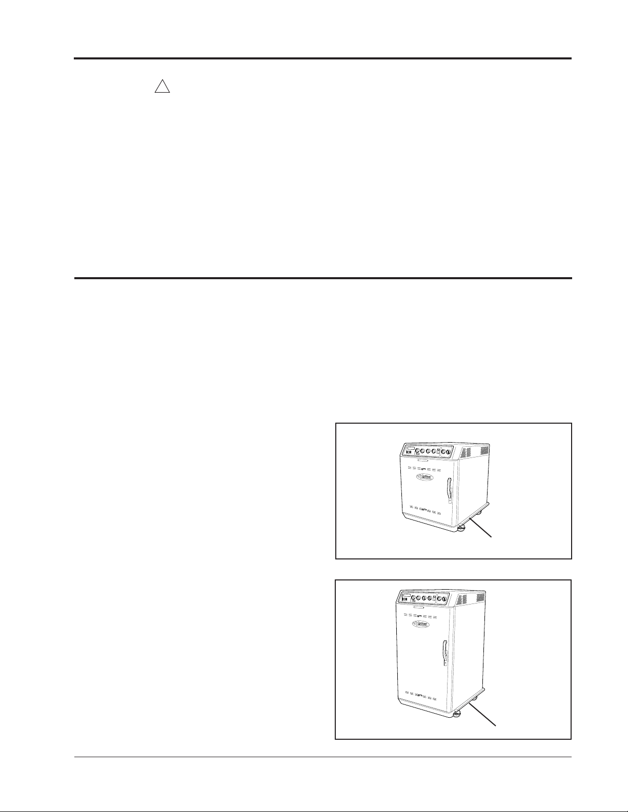
MODEL CS2-10S
The Model CS2-10S is identical to the Model CS2-10
model but also includes a smoker box and expanded
control panel for combined smoking and cooking benefits.
Note: Smoking should be done near an exhaust hood.
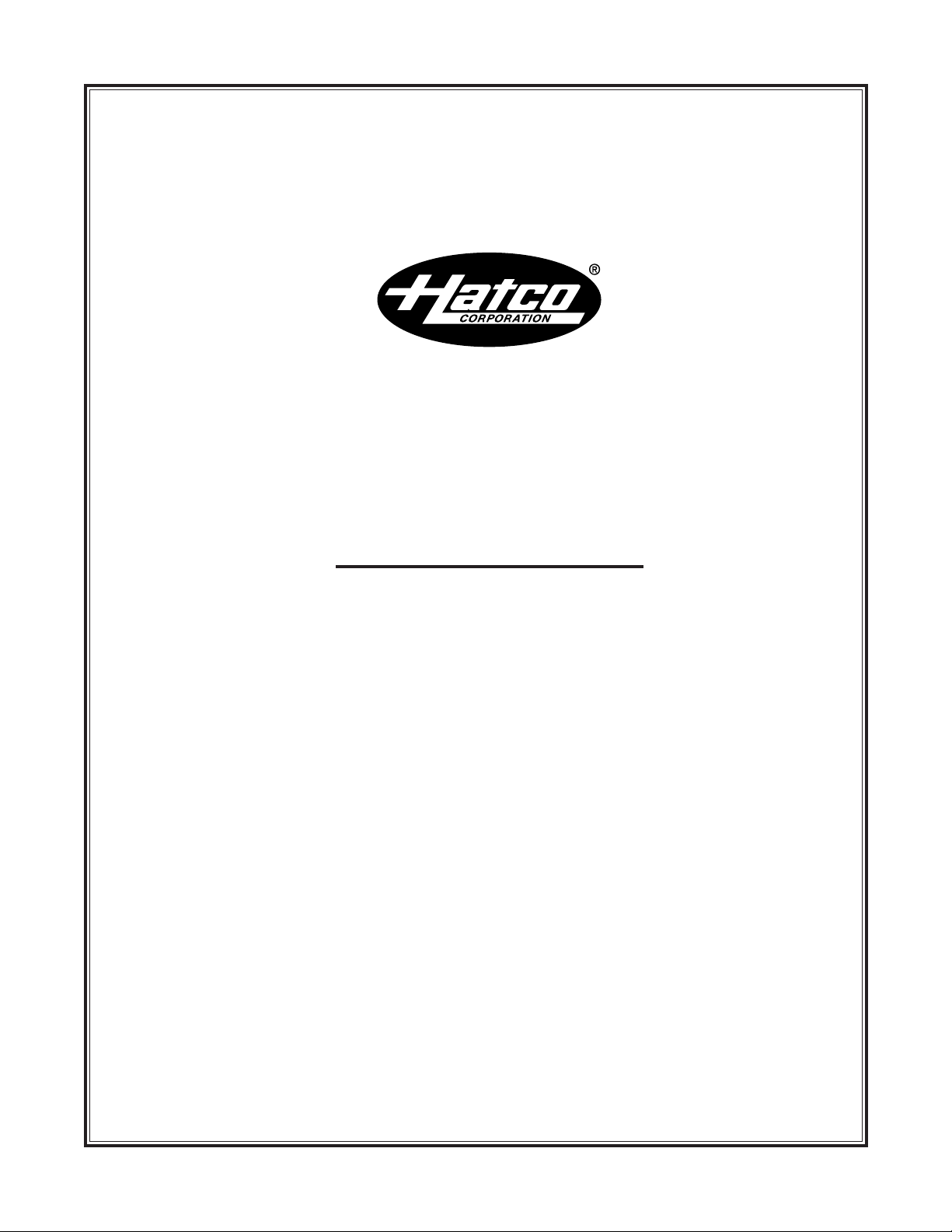
Unit shown with optional bumpers.
Figure 1. Cook & Hold Model CS2-5S
MODEL CS2-5S
The Chef System Cook & Hold Oven Model CS2-5S is
constructed the same as the CS2-5 but also includes a
smoker box and expanded control panel for combined
smoking and cooking benefits.
Note: 5-pan models can be ordered as a stacked unit.
Consult the factory. See Installation for stacking
instructions.
MODEL CS2-10
The Chef System Cook & Hold Oven Model CS2-10
Unit shown with optional bumpers.
Figure 2. Smoke & Hold Model CS2-10S
1
Form No. CS2M-0800
Page 4
SPECIFICATIONS
ELECTRICAL RATING CHART
Model Voltage Hertz Watts Amps Plug Configuration Shipping Weight
CS2-5L 120 60 1795 14.9 NEMA 5-15P/5-20P* 265 lbs. (120 kg)
CS2-5 208 60 2170 10.4 NEMA 6-15P 265 lbs. (120 kg)
CS2-5 240 60 2170 9.0 NEMA 6-15P 265 lbs. (120 kg)
COOKCOOK
CS2-5 220 50/60 2170 9.9 CEE 7/7 Schuko 265 lbs. (120 kg)
CS2-5 240 50/60 2170 9.0 BS-1363 265 lbs. (120 kg)
CS2-5SL 120 60 1945 16.2 NEMA 5-20P/5-30P* 265 lbs. (120 kg)
CS2-5S 208 60 2320 11.2 NEMA 6-15P 265 lbs. (120 kg)
CS2-5S 240 60 2320 9.7 NEMA 6-15P 265 lbs. (120 kg)
CS2-5S 220 50/60 2320 10.5 CEE 7/7 Schuko 265 lbs. (120 kg)
SMOKE
CS2-5S 240 50/60 2320 9.7 BS-1363 265 lbs. (120 kg)
208 60 2870 13.8 NEMA 6-15P 360 lbs. (163 kg)
CS2-10 240 60 2870 12.0 NEMA 6-15P 360 lbs. (163 kg)
220 50/60 2870 13.0 CEE 7/7 Schuko 360 lbs. (163 kg)
240 50/60 2870 12.0 BS 1363 360 lbs. (163 kg)
208 60 3020 14.5 NEMA 6-15P 360 lbs. (163 kg)
CS2-10S 240 60 3020 12.6 NEMA 6-15P/6-20P* 360 lbs. (163 kg)
SMOKE
220 50/60 3020 13.7 CEE 7/7 Schuko 360 lbs. (163 kg))
240 50/60 3020 12.6 BS 1363 360 lbs. (163 kg)
* For Canada
The electrical information in the shaded areas pertains to Export models only.
CAUTION
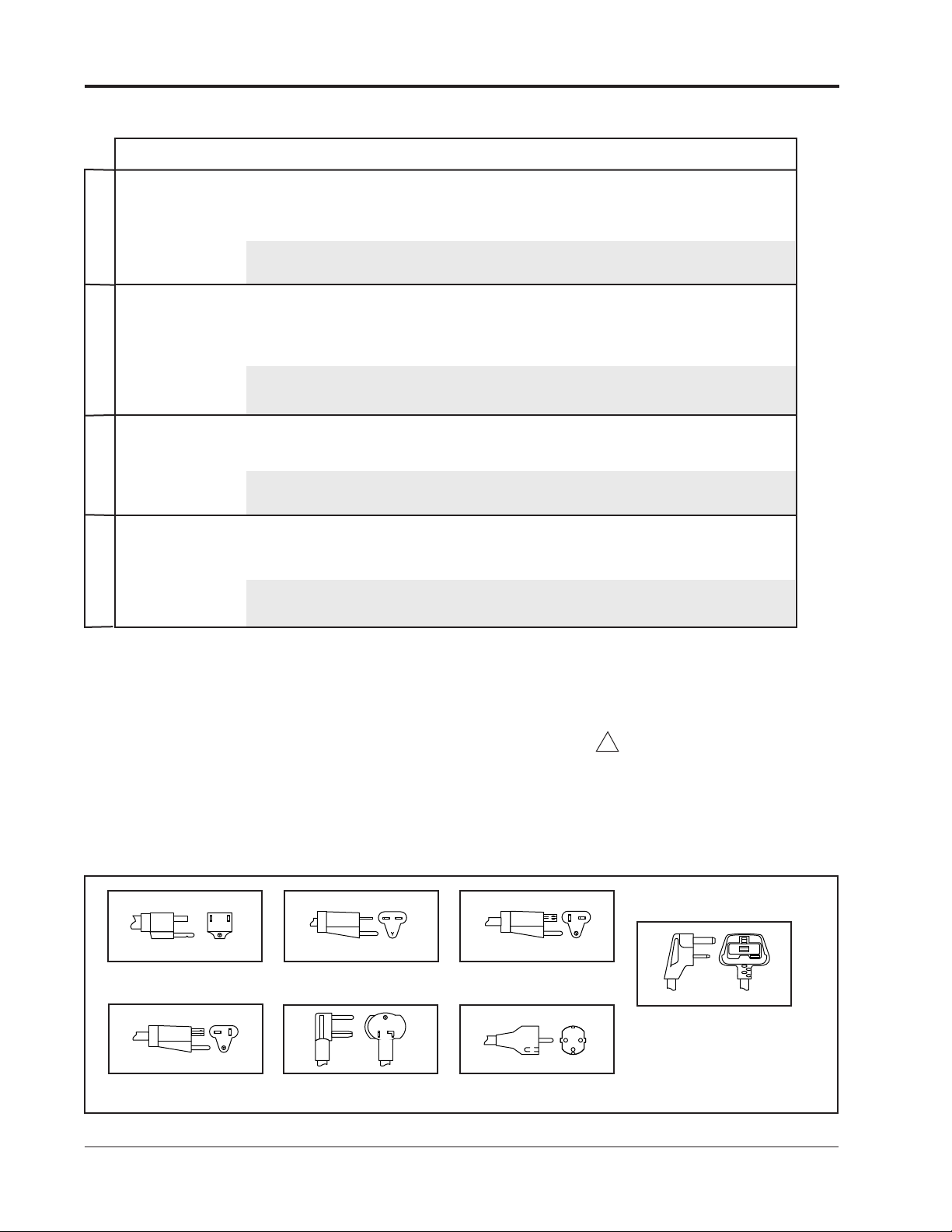
PLUG CONFIGURATIONS
Units are supplied from the factory with an electrical
cord and plug installed on the back of the unit. See
Figure 3.
Plug cabinet into an electrical outlet of the correct
voltage, size and plug configuration. If the plug and
receptacle do not match, contact a qualified electri-
!
cian to determine the proper voltage and size and
install the proper electrical outlet.
NEMA 5-15P
NEMA 6-15P
NEMA 5-20P
NEMA 6-20P
Form No. CS2M-0800
NEMA 5-30P
Figure 3. Plug Configurations.
BS-1363
CEE 7/7 Schuko
2
Page 5

26-1/4" (67 cm)
33-7/8" (86 cm)
34" (
86 cm)
32"
(81 cm)
With Low Profile Casters
FRONT VIEW
SIDE VIEW
26-1/4" (67 CM) 33-7/8" (86 CM)
52-1/4" (133 CM)
50-1/4" (128 CM)
With Low Profile Casters
FRONT VIEW
SIDE VIEW
5-Pan Models
10-Pan Models
5-Pan Stacked
FRONT VIEW
SIDE VIEW
26-1/4" (67 CM) 33-7/8" (86 CM)
65-5/
8" (167
c
m
)
63-
5/
8"
(
162
c
m)
Wit
h
Low
Pr
of
ile
Cas
t
er
s
Note: Optional bumpers add 2" (5 cm) to width of oven and 1" (3cm) to depth.
DIMENSIONS
SPECIFICATIONS
28-1/4" (72 cm)
28-1/4" (72 cm)
34-7/8" (89 cm)
Cabinet Opening:
18-1/4" W x 20-1/2" L
(46 x 52 cm)
helves on 3-1/2"
S
(8 cm) centers.
Angle Slides Clearance:
16-1/4" (41 cm)
34-7/8" (89 cm)
28-1/4" (72 cm)
Cabinet Opening:
18-1/4" W x 38-1/2" L
(46 x 98 cm)
Shelves on 3-1/2"
(8 cm) centers.
Angle Slides Clearance:
16-1/4" (41 cm)
34-7/8" (89 cm)
Figure 4. Dimensions.
3
Form No. CS2M-0800
Page 6

INSTALLATION
UNPACKING
1. Remove tape and protective film from all outside
surfaces of unit.
2. Remove tape and protective film from all internal
parts and surfaces.
3. Install parts as shown in Figure 5.
LOCATION
Locate the unit in an area that is convenient for use. The
location should be level to prevent the unit or its contents from accidental falling.
Note: All Smoke & Hold Ovens, and ovens equipped
with the 350º F (177º C) thermostat, should be located
underneath an exhaust hood. Consult your local codes.
Note: When installing rack supports, make sure row
of vent holes are located at the bottom and arrows on
side are pointing up
Wire Rack
!
CAUTION
For safe and proper operation, the unit must be
located a reasonable distance from combustible walls
and materials. If safe distances are not maintained,
discoloration or combustion could occur.
CAUTION
!
Locate the unit in an area that is convenient for use
and where the room temperature is between 60º F
(16º C) and 105º F (41º C). The location should be
level to prevent the unit or its contents from accidentally falling, and strong enough to support the weight
of the unit and food product.
Cabinet
Rack Support
Probe
Locator Plate*
Drip Pan
Front Drip Tray
Figure 5. Exploded View - CS2-5S Shown
*
Smoker Box Lid*
Smoker Box*
Locator
Plate*
Bottom Shelf
Note: Make sure arrow is
pointing up when installed.
*Included with smoker option only.
Form No. CS2M-0800
4
Page 7

5-PAN STACKED
Note: When stacking ovens and one of them is a smoker
oven, install the smoker oven on top.
1. See Figure 6. The top unit intended for stacking has
a mounting bracket attached to the bottom in place
of casters.
2. Remove the two outer screws from the top rear of
the bottom unit.
3. Place the top oven (at least two people required) on
top of the bottom oven and secure in place using the
original screws removed in step 2.
INSTALLATION
Mounting Holes
Figure 6. Model 5-Pan Stacking Ovens
5
Form No. CS2M-0800
Page 8

OPERATION
GENERAL
Refer to Cooking Guide for specific recipes and helpful
hints. Oven door is equipped with vents that can be
adjusted to desired setting. See Cooking Guide for
details.
OVEN OPERATION
1. Plug unit into an electrical outlet of the correct voltage, size and plug configuration. See Specifications
for details.
Note: Set oven controls from left to right.
2. Turn the ON/OFF Switch to the ON position. See
Figure 7.
3. Select one of the following cooking modes first by
adjusting Cooking Mode Selector Dial:
• Cook by time (TIMED COOK & HOLD).
• Cook by product internal temperature (PROBE
COOK & HOLD).
• Cook with manual timer (MANUAL TIMER).
No Hold cycle in this mode.
4. Adjust Cook Time, Probe Temperature, or Manual
Timer (depending on mode selected) by adjusting
Time/Probe Temperature Dial.
5. Adjust Cook Temperature Dial to desired setting.
6. Adjust Hold Temperature Dial to desired setting
Note: No Hold cycle in Manual Timer mode.
7. Press Start Button to begin preheat.
Cooking Guide for smoking recommendations and
instructions.
The smoke delay interval will begin when the Start
Button is pushed to initiate the cook cycle.
Adjustments are in 15 minute increments.
11. Adjust Smoke Timer. Timer is programmable in 5
minute increments, from 5 minutes to 4 hours.
Continuous smoking is also available by turning the
dial counterclockwise to the continuous setting.
Timed Cook & Hold Mode: When set time has
elapsed, unit shifts to HOLD automatically and HOLD
display indicates total time product has been in Hold
mode. Refer to Cooking Guide for minimum Hold
times.
Probe Cook & Hold Mode: After preset internal product temperature is reached, unit shifts to Hold mode
automatically and Hold display indicates total time
product has been in Hold mode. Refer to Cooking Guide
for minimum Hold times.
Note: Make sure probe is plugged into front of control
panel, aligning the red dot on the probe with red dot on
control panel (wider prong to the left side), and inserted
into meat product.
Manual Timer Mode: When set time has elapsed, unit
gives an audible signal and displays a message in the
LCD window. Product should be removed if done. Oven
will not go into Hold mode. Cook temperature will be
maintained.
Oven will automatically preheat ten degrees over
cook temperature setting. When the oven is preheated, an audible beep will sound and the visual display
will indicate that preheat is complete and product
should be placed in the oven.
8. Load oven with food product.
9. Press Start Button to begin cooking cycle.
Note: Failure to push Start Button will keep oven in the
preheat mode.
THE FOLLOWING STEPS APPLY TO SMOKER
OVENS ONLY.
10. After starting preheat
Delay feature allows operator to delay smoking for
as long as 20 hours after Cooking cycle begins. See
Form No. CS2M-0800
adjust Smoke Delay. Smoke
Program cycle can be repeated by pressing Start again.
Note: All oven cycles will retain its program until a
change is made, even if the oven has been turned off.
Note: Adjustments to the dial settings on the control
panel can be made at any time during the Preheat,
Cooking or Holding process.
Note: Unit is equipped with a power failure indicator
feature. In the event that power is interrupted for more
than 10 minutes, display will indicate total interruption
time.
Note: Push the View Oven Temperature Button at any
time to observe actual oven temperature in LCD message window.
6
Page 9

Chef System S2
Smoker
MANUAL
TIMER
COOK& HOLD
PROBE
TIMED
COOK& HOLD
S
TART
O
VEN
T
EMP
SMOKE DELAY SMOKE TIME
PREHEAT
COOK
COOK TEMP
HOLD TEMP
PROBE OUTLET
PREHEAT
COOKING
HOLDING
HEAT ON
COOK TIME 04H30M
TIME LEFT 01H23M
OPERATION
LCD
MESSAGE
WINDOW
ON/OFF
SWITCH
COOKING
MODE
SELECTOR DIAL
COOKING
MODE
COOK
TEMPERATURE
DIAL
PROBE
OUTLET
TEMPERATURE
INDICATOR
Figure 7. Control Panel
GENERAL
The Hatco Chef System Cook & Hold Ovens are
designed for maximum durability and performance, with
minimum maintenance.
TEMPERATURE
TIME/PROBE
DIAL
HOLD
DIAL
Chef System S2
START
BUTTON
VIEW OVEN
TEMPERATURE
BUTTON
Smoker
SMOKE
MODE
INDICATOR
MAINTENANCE
Food pans and wire racks should be removed and
washed. Rack support wall panels and bottom shelf
should also be removed for periodic cleaning. Refer to
Figure 5 for proper installation.
SMOKER
DELAY
DIAL
SMOKE
TIMER
DIAL
!
WARNING
To avoid any injury, turn the power switch off,
unplug the unit from the power source and allow to
cool before performing any maintenance.
CLEANING
To preserve the bright finish of the Chef System Cook
& Hold Oven, it is recommended that the exterior and
interior surfaces be wiped daily with a damp cloth.
Stubborn stains may be removed with a good stainless
steel cleaner or a non-abrasive cleaner. Hard to reach
areas should be cleaned with a small brush and mild
soap.
Abrasive cleaners could scratch the finish of your
Cook & Hold Oven.
Do not steam clean the interior or flood with water
or liquid solution.
!
CAUTION
7
Form No. CS2M-0800
Page 10

ACCESSORIES
PERIMETER BUMPERS
The Perimeter Bumpers protect the Chef System oven
from the heavy-duty use of food service operations. The
bumpers add 2" (5 cm) to the width of the unit and 1" (3
cm) to the depth.
HEAVY-DUTY 5” (13 cm) CASTERS
These heavy-duty casters enhance the portability of the
oven. These casters add 1" (3 cm) to the standard
height.
LOW PROFILE CASTERS
Low profile casters are also available as an option.
When mounted on the unit, they lower the standard
height by 2" (5 cm).
RIB RACK - STAINLESS STEEL
The stainless steel rib rack keeps ribs upright for perfect
cooking every time. Holds 13 slabs of baby back ribs.
GLO-RAY CARVING STATION
Combine this carving station with the Chef System
Oven to produce a complete serving station for buffet
lines. Ceramic heating elements extend food holding
time. Available with or without base heat and features
an adjustable clearance of 17-1/2" to 23-1/2" (45-60
cm).
WIRE RACKS
Additional wire racks are available from the factory or
your local authorized dealer.
SHEET PANS
Additional sheet pans are available from the factory or
your local authorized dealer.
STAINLESS STEEL LEGS
Stationary stainless steel legs are available for added
stability.
Form No. CS2M-0800
8
Page 11

HATCO LIMITED WARRANTY
1. PRODUCT WARRANTY
Hatco warrants the products that it manufactures (the
“Products”) to be free from defects in materials and
workmanship, under normal use and service, for a
period of one (1) year from the date of purchase
when installed and maintained in accordance with
Hatco’s written instructions. Buyer must establish the
product’s purchase date by returning Hatco’s
Warranty Registration Card or by other means satisfactory to Hatco in its sole discretion.
Hatco warrants the following Product components to
be free from defects in materials and workmanship
from the date of purchase (subject to the foregoing
conditions) for the period(s) of time and on the conditions listed below:
a) One (1) Year Parts and Labor PLUS One (1)
Additional Year Parts-Only Warranty:
Toaster Elements (metal sheathed)
Drawer Warmer Elements (metal sheathed)
Drawer Warmer Drawer Rollers and Slides
Food Warmer Elements (metal sheathed)
Display Warmer Elements (metal sheathed air
heating)
Holding Cabinet Elements (metal sheathed air
heating)
Cook and Hold Oven Elements (metal sheathed)
b) One (1) Year Parts and Labor PLUS Four (4)
Additional Years Parts-Only Warranty on
pro-rated terms that Hatco will explain at
Buyer’s Request:
Powermite Gas Booster (stainless steel)
3CS and FR Tanks
Mini Compact Tanks (stainless steel)
c) One (1) Year Parts and Labor PLUS Four (4)
Additional Years Parts-Only Warranty PLUS
Five (5) Year Parts-Only Warranty on prorated terms that Hatco will explain at Buyer’s
Request:
Booster Heater Tanks (Castone)
d) One (1) Year Parts-Only Warranty for
components not installed by Hatco:
Accessory Components (including but not
limited to valves, gauges and remote switches)
THE FOREGOING WARRANTIES ARE
EXCLUSIVE AND IN LIEU OF ANY OTHER
WARRANTY, EXPRESSED OR IMPLIED,
INCLUDING BUT NOT LIMITED TO ANY
IMPLIED WARRANTY OF MERCHANTABILITY
OR FITNESS FOR A PARTICULAR PURPOSE OR
PATENT OR OTHER INTELLECTUAL
PROPERTY RIGHT INFRINGEMENT. Without limiting the generality of the foregoing, SUCH
WARRANTIES DO NOT COVER: Coated incandescent light bulbs, lamp warmer heat bulbs, glass components or Product failure caused by liming or sediment buildup in tanks, Product misuse, tampering or
misapplication, improper installation, application of
improper voltage, or recalibration of thermostats or
high limit switches.
2. LIMITATION OF REMEDIES AND
DAMAGES
Hatco’s liability and Buyer’s exclusive remedy
hereunder will be limited solely, at Hatco’s option,
to repair or replacement by a Hatco-authorized
service agency (other than where Buyer is located
outside of the United States or Canada, in which case
Hatco’s liability and Buyer’s exclusive remedy hereunder will be limited solely to replacement of part
under warranty) with respect to any claim made within the applicable warranty period referred to above.
Without limiting the generality of the foregoing, all
portable Products (as defined in N.S.F. 4-4.28.4) shall
be delivered by Buyer, at its sole expense, to the
nearest Hatco-authorized service agency for replacement or repair. Hatco reserves the right to accept or
reject any such claim in whole or in part. Hatco will
not accept the return of any Product without prior
written approval from Hatco, and all such approved
returns shall be made at Buyer’s sole expense.
HATCO WILL NOT BE LIABLE, UNDER ANY
CIRCUMSTANCES, FOR CONSEQUENTIAL OR
INCIDENTAL DAMAGES, INCLUDING BUT
NOT LIMITED TO LABOR COSTS OR LOST
PROFITS RESULTING FROM THE USE OF OR
INABILITY TO USE THE PRODUCTS OR FROM
THE PRODUCTS BEING INCORPORATED IN OR
BECOMING A COMPONENT OF ANY OTHER
PRODUCT OR GOODS.
9
Form No. CS2M-0800
Page 12

ALABAMA
Jones McLeod Appl. Svc.
irmingham 205-251-0159
B
ARIZONA
Auth. Comm. Food Equip.
hoenix 602-234-2443
P
Byassee Equipment Co.
Phoenix 602-252-0402
ALIFORNIA
C
Industrial Electric
Huntington Beach 714-379-7100
Chapman Appl. Service
San Diego 619-298-7106
P & D Appliance
S. San Francisco 650-635-1900
OLORADO
C
All City Service
Denver 303-454-9500
awkins Commercial Appliance
H
Englewood 303-781-5548
DELAWARE
Food Equipment Service
ilmington 302-996-9363
W
LORIDA
F
Whaley Foodservice Repair
acksonville 904-725-7800
J
ass Service Co., Inc.
N
Orlando 407-425-2681
B.G.S.I.
Pompano Beach 954-971-0456
Comm. Appliance Service
Tampa 813-663-0313
GEORGIA
Southeastern Rest. Svc.
Norcross 770-446-6177
HAWAII
Burney’s Comm. Service, Inc.
Honolulu 808-848-1466
Food Equip Parts & Service
Honolulu 808-847-4871
ILLINOIS
Parts Town
Broadview 708-865-7278
Eichenauer Elec. Service
Decatur 217-429-4229
Midwest Elec. Appl. Service
Elmhurst 630-279-8000
Cone’s Repair Service
Moline 309-797-5323
INDIANA
Comm. Parts & Service, Inc.
Indianapolis 317-545-9655
IOWA
Electric Motor Service Co.
Davenport 319-323-1823
KENTUCKY
Comm. Parts & Service, Inc.
Louisville 502-367-1788
LOUISIANA
Chandlers Parts & Service
Baton Rouge 225-272-6620
HATCO AUTHORIZED PARTS DISTRIBUTORS
OUISIANA (Continued)
L
Bana Comm. Parts, Inc.
hreveport 318-631-6550
S
ARYLAND
M
Electric Motor Service
altimore 410-467-8080
B
CS Service, Inc.
G
Silver Spring 301-585-7550
MASSACHUSETTS
ce Service Co., Inc.
A
Needham 781-449-4220
MICHIGAN
ommercial Kitchen Service
C
Bay City 517-893-4561
Bildons Appliance Service
etroit 248-478-3320
D
idwest Food Equip. Service
M
Grandville 616-261-2000
MINNESOTA
etro Appliance Service
M
Minneapolis 612-546-4221
MISSOURI
GCS Service, Inc.
ansas City 816-920-5999
K
Commercial Kitchen Services
St. Louis 314-890-0700
Kaemmerlen Parts & Service
St. Louis 314-535-2222
NEBRASKA
Anderson Electric
Omaha 402-341-1414
NEVADA
Burney’s Commercial
Las Vegas 702-736-0006
NEW JERSEY
Jay Hill Repair
Fairfield 973-575-9145
Service Plus
Flanders 973-691-6300
NEW YORK
Acme American Repairs, Inc.
Brooklyn 718-456-6544
Alpro Service Co.
Brooklyn 718-386-2515
Appliance Installation
Buffalo 716-884-7425
Northern Parts Dist.
Plattsburgh 518-563-3200
J. B. Brady, Inc.
Syracuse 315-422-9271
NORTH CAROLINA
Authorized Appliance
Charlotte 704-377-4501
OHIO
Akron/Canton Comm. Svc. Inc.
Akron 330-753-6635
Certified Service Center
Cincinnati 513-772-6600
ARR/CRS, Inc.
Columbus 614-476-3225
Electrical Appl. Repair Service
Independence 216-459-8700
OHIO (Continued)
. A. Wichman Co.
E
Toledo 419-385-9121
OKLAHOMA
agar Rest. Service, Inc.
H
Oklahoma City 405-235-2184
Krueger, Inc.
klahoma City 405-528-8883
O
OREGON
Bressie Electric Co.
ortland 503-231-7171
P
Ron’s Service, Inc.
Portland 503-624-0890
PENNSYLVANIA
Authorized Factory Service
oraopolis 412-262-2330
C
AST Comm. Appl. Service
F
Philadelphia 215-922-6245
GCS Service, Inc.
ittsburgh 412-787-1970
P
K & D Service Co.
arrisburg 717-236-9039
H
Elmer Schultz Services
Philadelphia 215-627-5401
Electric Repair Co.
Reading 610-376-5444
RHODE ISLAND
Marshall Electric Co.
Providence 401-331-1163
SOUTH CAROLINA
Whaley Foodservice Repair
W. Columbia 803-791-4420
TENNESSEE
Camp Electric
Memphis 901-527-7543
TEXAS
City Kitchen Service Co.
Austin 512-719-4445
Stove Parts Supply
Fort Worth 817-831-0381
Armstrong Repair Service
Houston 713-666-7100
Commercial Kitchen Repair Co.
San Antonio 210-735-2811
San Antonio Rest. Equip.
San Antonio 210-824-3271
UTAH
Peterson’s Commercial Parts & Svc.
Salt Lake City 801-487-3653
VIRGINIA
Daubers
Norfolk 757-855-4097
Daubers
Springfield 703-866-3600
WASHINGTON
Restaurant Appl. Service
Seattle 206-524-8200
WISCONSIN
A.S.C., Inc.
Madison 608-246-3160
A.S.C., Inc.
Milwaukee 414-543-6460
Printed in U.S.A. April 1999
HATCO CORPORATION
P.O. Box 340500, Milwaukee, WI 53234-0500 U.S.A.
(800) 558-0607 (414) 671-6350
Parts & Service Fax (800) 690-2966 Int’l. Fax (414) 671-3976
Web Site: www.hatcocorp.com
P/N 07.04.293.00 Form No. CS2M-0800
 Loading...