

Page 1
CHEF SYSTEM
®
Humidified Holding Cabinet
CS2H Series
Installation &
Operating Manual
I&W # 07.05.116.00
This manual contains important safety information
concerning the maintenance, use and operation of
this product. Failure to follow the instructions
contained in this manual may result in serious injury.
If you are unable to understand the contents of this
manual, please bring it to the attention of your
supervisor. Do not operate this equipment unless you
have read and understood the contents of this
manual.
Este manual contiene importante información sobre
seguridad concerniente al mantenimiento, uso
y operación de este producto. Cualquier falla en el
seguimiento de las instrucciones contenidas en este
manual puede resultar en un serio daño. Si usted no
puede entender el contenido de este manual por
favor pregunte a su supervisor. No opere este equipo
al menos que haya leído y comprendido el contenido
de este manual.
Page 2

i
INTRODUCTION
Hatco Chef System Humidified Holding Cabinets are
designed for simple operation and exceptional holding
performance in 5- or 10-pan models. The CS2H Series
provides Hatco reliability in a high humidity holding
cabinet that keeps a wide range of menu items hot for
extended holding times.
With five levels of humidity, crisp food will stay crisp
and moist food moist. The 90° to 185°F (32°-85°C) air
temperature range allows precise temperature and
humidity control for proofing and holding.
This portable Holding Cabinet is ideal for serving
counters, buffet lines, drive-up windows, point-ofservice, or preparation areas. 5-pan models can be
stacked together to create greater holding capacity, or
add a 5-pan Chef System Cook and Holding Oven or
Glo-Ray
®
Carving Station on top to increase versatility.
T
h
is m
anual p
rov
ides th
e in
stallation
, safety an
d
operating in
struction
s for the C
hef S
y
stem
H
um
idified
H
old
ing
C
abinets. W
e recom
m
end all installatio
n,
op
erating and
safety
instru
ction
s ap
pearin
g in
th
is
m
anual be read prior to in
stallation
o
r op
eration of y
ou
r
H
atco C
h
ef S
ystem
. S
afety
instructio
ns th
at appear in
th
is m
an
ual after a w
arnin
g sym
b
ol an
d th
e w
ords
W
A
R
N
IN
G
or C
A
U
T
IO
N
p
rinted in
b
old
face are v
ery
im
po
rtan
t.
W
A
R
N
IN
G
m
eans there is the po
ssib
ility
of serio
us in
jury
or d
eath to yo
urself o
r others.
C
A
U
T
IO
N
m
eans there is the po
ssibility of m
ino
r
or m
o
derate injury.
C
A
U
T
IO
N
w
ith
out the sym
bo
l
sig
nifies th
e p
ossibility of eq
uipm
en
t o
r pro
perty
dam
ag
e o
nly.
H
atco C
hef S
y
stem
H
um
idified
H
olding C
abinets are a
p
rod
uct o
f extensive research and
field testing. T
h
e
m
aterials used w
ere selected
for m
axim
um
durability,
attractive app
earance and op
tim
um
perform
ance. E
very
u
nit is thorou
ghly in
spected and tested prio
r to shipm
ent.
CONTENTS
Important Owner Information.....................................i
Introduction ...................................................................i
Important Safety Instructions .....................................1
Model Descriptions .......................................................2
All Models ..............................................................2
CS2H-5 Models ......................................................2
CS2H-5-2 Models ...................................................2
CS2H-10 Models ....................................................2
CS2H-10-2 Models .................................................2
Specifications.................................................................3
Electrical Rating Chart............................................3
Dimensions..............................................................3
Plug Configurations ................................................4
Installation.....................................................................4
Unpacking ...............................................................4
Location ..................................................................4
Stacking Information...............................................5
Stacking Rules.........................................................5
Operation.......................................................................6
General ....................................................................6
Water Fill Instructions.............................................6
Food Holding Guide ...............................................7
Maintenance ..................................................................8
General ....................................................................8
Cleaning ..................................................................8
Removing Lime and Mineral Deposits...................9
Accessories...................................................................10
Stacking Hardware................................................10
Food Pans..............................................................10
Wire Racks............................................................10
Hatco Limited Warranty............................................11
Authorized Parts Distributors....................Back Cover
IMPORTANT OWNER INFORMATION
Record the model number, serial number (identification
plate located on the back of the unit), voltage and
purchase date of your Chef System Humidified Holding
Cabinet in the spaces below. Please have this
information available when calling Hatco for service
assistance.
Model No. ____________________________________
Serial No. ____________________________________
Voltage ______________________________________
Date of Purchase ______________________________
Business 8:00 a.m. to 5:00 p.m.
Hours: Central Standard Time
(Summer Hours: June to September –
8:00 a.m. to 5:00 p.m. C.D.T.
Monday through Thursday
8:00 a.m. to 2:30 p.m. C.D.T. Friday)
Telephone: (800) 558-0607; (414) 671-6350
Fax: (800) 690-2966 (Parts & Service)
(414) 671-3976 (International)
Additional information can be found by visiting our
web site at www.hatcocorp.com
Form No. CS2HM-0102
Page 3
CAUTIONS
Some exterior surfaces on the unit will get hot.
Use caution when touching these areas to
avoid injury.
Water in the unit and holding vessel is very hot.
Wear protective gloves and proper attire when
operating to avoid injury.
Locate the unit in an area that is convenient for
use and where the room temperature is between
60°F (16°C) and 105°F (41°C). The location should
be level to prevent the unit or its contents from
accidentally falling, and strong enough to support
the weight of the unit and food product.
Hot water vapor will exit top of doorway when
opening door.
Do not steam clean the interior or flood with
water or liquid solution.
CAUTIONS
Use only non-abrasive cleaners. Abrasive
cleaners could scratch the finish of your unit
marring its appearance and making it susceptible
to soil accumulation.
Inspect daily for lime buildup inside unit.
Excessive amounts can affect unit performance
and reduce the operating life of the unit.
Water Quality Requirements - Incoming water in
excess of 3.0 grains of hardness per gallon (GPG)
(.75 grains of hardness per liter) must be treated
and softened before being used. Water containing
over 3.0 GPG (.75 GPL) will decrease the
efficiency and reduce the operating life of the unit.
The delimer used should be a safe, non-toxic,
non-corrosive solution. Follow the delimer’s
instructions for proper mixture of water and
delimer solution.
When stacking a CS2 and CS2H unit, the CS2H
series unit is always on the bottom.
IMPORTANT SAFETY INSTRUCTIONS
1
WARNINGS
Plug cabinet into a properly grounded electrical
outlet of the correct voltage, size and plug
configuration. If the plug and receptacle do not
match, contact a qualified electrician to determine
the proper voltage and size and install the proper
electrical outlet.
To avoid any injury, turn the power off to the unit
and allow to cool before draining.
To avoid any injury, turn the power switch off at
the fuse disconnect switch/circuit breaker or
unplug the unit from the power source and allow
to cool completely before performing any
maintenance or cleaning.
To prevent electric shock, always unplug the unit
before performing cleaning or maintenance.
The unit must be transported in an
upright position.
Set operating temperature to 170°F for food
products that must be over 150°F.
For safe and proper operation, the unit must be
located a reasonable distance from combustible
walls and materials. If safe distances are not
maintained, discoloration or combustion
could occur.
If service is required on this unit, contact your
Authorized Hatco Service Agent, or contact the
Hatco Service Department at 800-558-0607 or
414-671-6350; fax 800-690-2966 or International
fax 414-671-3976.
This product has no “user” serviceable parts. To
avoid damage to the unit or injury to personnel,
use only Authorized Hatco Service Agents and
Genuine Hatco Parts when service is required.
Genuine Hatco Replacement Parts are specified to
operate safely in the environments in which they
are used. Some aftermarket or generic
replacement parts do not have the characteristics
that will allow them to operate safely in Hatco
equipment. It is essential to use Hatco
Replacement Parts when repairing Hatco
equipment. Failure to use Hatco Replacement
Parts may subject operators of the equipment to
hazardous electrical voltage, resulting in electrical
shock or burn.
Form No. CS2HM-0102
IMPORTANT! Read the following important safety instructions to avoid personal injury or death,
and to avoid damage to the equipment or property.
Page 4
MODEL DESCRIPTIONS
2
Form No. CS2HM-0102
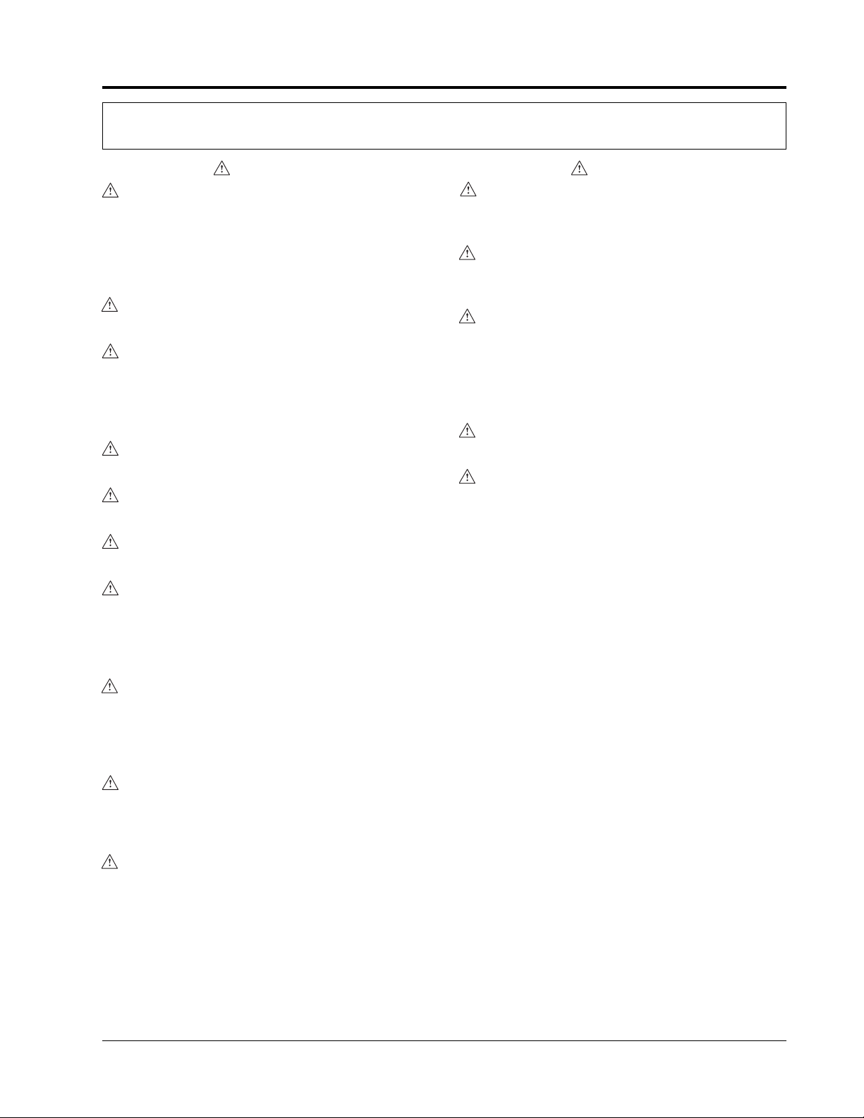
Figure 1. Humidified Holding Cabinet - Model CS2H-5
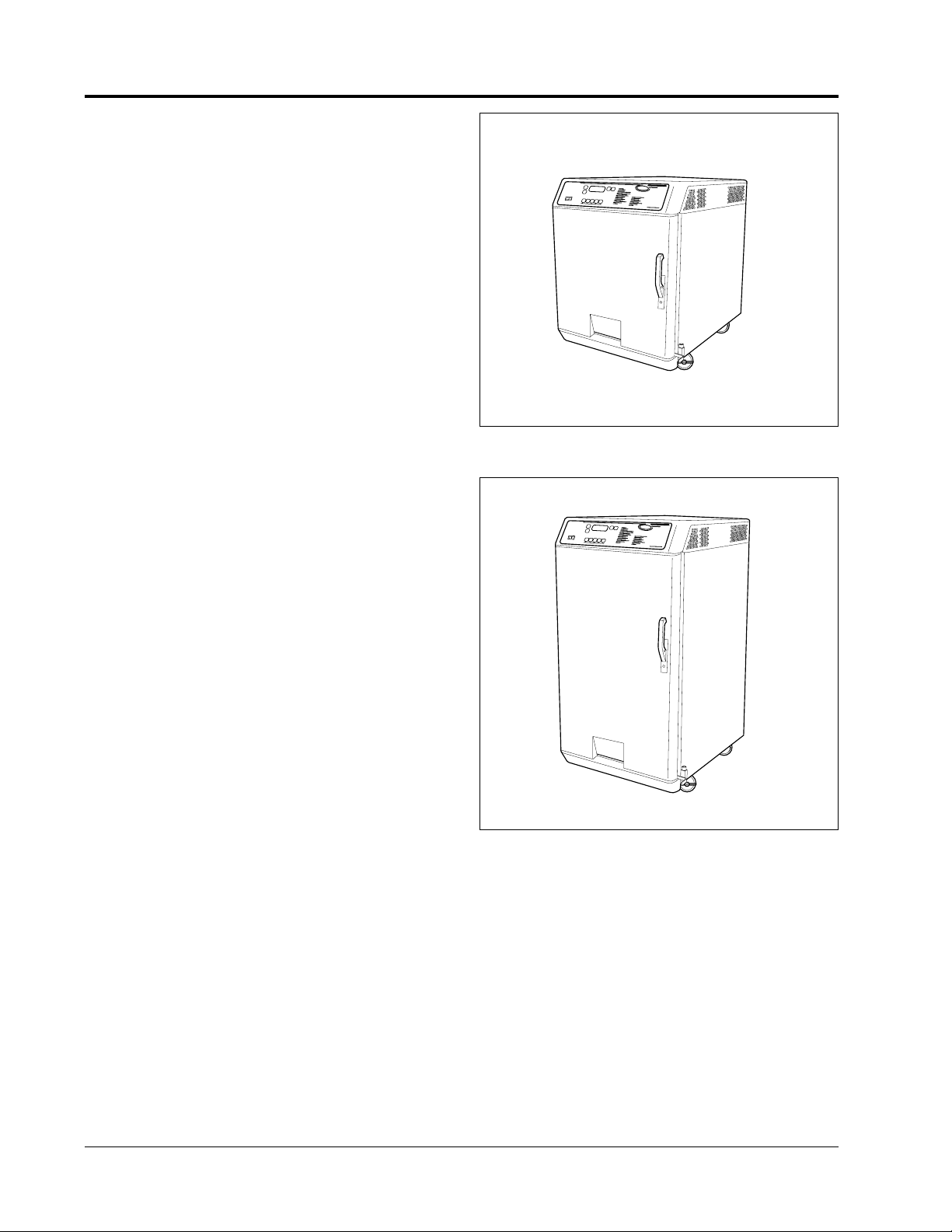
Figure 2. Humidified Holding Cabinet - Model CS2H-10
ALL MODELS
Chef System Humidified Holding Cabinets come in
5-pan or 10-pan models. The cabinets are constructed of
easy-to-clean stainless steel with a fully welded interior
cavity and feature insulated side walls. All models
come fully equipped with 4" (10 cm) locking casters,
6' (183 cm) attached cord with plug, a water reservoir,
humidity selector control, temperature selector control,
ON/OFF switch and indicating lights.
MODEL CS2H-5
The Chef System Humidified Holding Cabinet Model
CS2H-5 comes standard with five wire racks on each
side to support ten 2-1/2" (6 cm) deep steamtable pans
(two per shelf) or five 1" (3 cm) deep baking pans.
Additional wire racks can be added, two per side, see
ACCESSORIES for details. This model has one door on
the control side of the unit.
MODEL CS2H-5-2
The Chef System Humidified Holding Cabinet Model
CS2H-5-2 comes standard with five wire racks on each
side to support ten 2-1/2" (6 cm) deep steamtable pans
(two per shelf) or five 1" (3 cm) deep baking pans.
Additional wire racks can be added, two per side, see
ACCESSORIES for details. This model has two doors
which allows for loading and unloading of food product
on either side of the unit.
Note: 5-pan models can be ordered as a stacked
unit. Consult the factory. See INSTALLATION for
stacking instructions.
MODEL CS2H-10
The Chef System Humidified Holding Cabinet Model
CS2H-10 comes standard with ten wire racks on each
side to support twenty 2-1/2" (6 cm) deep steamtable
pans (two per shelf) or ten 1" (3 cm) deep baking pans.
Additional wire racks can be added, two per side, see
ACCESSORIES for details. This model has one door on
the control side of the unit.
MODEL CS2H-10-2
The Chef System Humidified Holding Cabinet Model
CS2H-10-2 comes standard with ten wire racks on each
side to support twenty 2-1/2" (6 cm) deep steamtable
pans (two per shelf) or ten 1" (3 cm) deep baking pans.
Additional wire racks can be added, two per side, see
ACCESSORIES for details. This model has two doors
which allows for loading and unloading of food product
on either side of the unit.
Page 5
SPECIFICATIONS
3
ELECTRICAL RATING CHART
Form No. CS2HM-0102
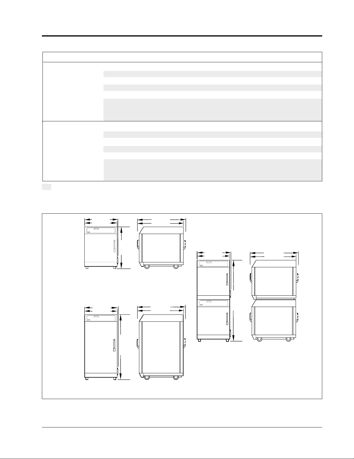
DIMENSIONS
Figure 4. Dimensions
26-1/4" (67 cm)
34" (86 cm)
34" (86 cm)
FRONT VIEW
SIDE VIEW
26-1/4" (67 CM)
26-7/8" (68 CM)
51-1/2" (131 CM)
FRONT VIEW
SIDE VIEW
5-Pan Models
10-Pan Models
5-Pan Stacked
FRONT VIEW
SIDE VIEW
6
5
-5
/8
"
(1
6
7
c
m
)
35-1/4" (90cm)
26-7/8" (68 cm)
34" (86 cm)
35-1/4" (90cm)
26-1/4" (67 cm)
26-7/8" (68 cm)
34" (86 cm)
35-1/4" (90cm)
Model Voltage Hertz Watts Amps Plug Configuration Shipping Weight
CS2H-5 & CS2H-5-2 120 60 2350 19.6 NEMA 5-20P 240 lbs. (109 kg)
200 50 2350 11.8 NONE 240 lbs. (109 kg)
208 60 2350 11.3 NEMA 6-15P 240 lbs. (109 kg)
220 50 2350 10.7 CEE 7/7 Schuko 240 lbs. (109 kg)
240 60 2350 9.8 NEMA 6-15P 240 lbs. (109 kg)
240 50 2350 9.8 BS 1363 240 lbs. (109 kg)
220-230 CE 50 2350 10.2-10.7 CEE 7/7 Schuko 240 lbs. (109 kg)
230-240 CE 50 2350 9.8-10.2 BS 1363 240 lbs. (109 kg)
CS2H-10 & CS2H-10-2 120 60 2350 19.6 NEMA 5-20P 320 lbs. (145 kg)
200 50 2350 11.8 NONE 320 lbs. (145 kg)
208 60 2350 11.3 NEMA 6-15P 320 lbs. (145 kg)
220 50 2350 10.7 CEE 7/7 Schuko 320 lbs. (145 kg)
240 60 2350 9.8 NEMA 6-15P 320 lbs. (145 kg)
240 50 2350 9.8 BS 1363 320 lbs. (145 kg)
220-230 CE 50 2350 10.2-10.7 CEE 7/7 Schuko 320 lbs. (145 kg)
230-240 CE 50 2350 9.8-10.2 BS 1363 320 lbs. (145 kg)
The electrical information in the shaded areas pertains to Export models only.
Page 6

INSTALLATION
SPECIFICATIONS
4
Form No. CS2HM-0102
UNPACKING
1. Remove tape and protective film from all outside
surfaces of unit.
2. Remove tape and protective film from all internal
parts and surfaces.
3. Install parts as shown in Figure 5.
LOCATION
Locate the unit in an area that is convenient for use. The
location should be level to prevent the unit or its
contents from accidental falling.
WARNING
The unit must be transported in an upright position.
WARNING
For safe and proper operation, the unit must be
located a reasonable distance from combustible walls
and materials. If safe distances are not maintained,
discoloration or combustion could occur.
CAUTION
Locate the unit in an area that is convenient for use
and where the room temperature is between 60°F
(16°C) and 105°F (41°C). The location should be
level to prevent the unit or its contents from
accidentally falling, and strong enough to support
the weight of the unit and food product.
Figure 5. Exploded View
Rack Support
Cabinet
Wire Rack
Front Water Tray
Drain Tube
PLUG CONFIGURATIONS
Units are supplied from the factory with an electrical
cord and plug. See Figure 3.
WARNING
Plug cabinet into a properly grounded electrical
outlet of the correct voltage, size and plug
configuration. If the plug and receptacle do not
match, contact a qualified electrician to determine
the proper voltage and size and install the proper
electrical outlet.
NEMA 5-20P
BS 1363 CEE 7/7 Schuko
NEMA 6-15P
Figure 3. Plug Configurations
Page 7

INSTALLATION
5
Form No. CS2HM-0102
STACKING INFORMATION
CAUTION
When stacking units, the CS2H series unit is always
on the bottom.
Refer to Figure 6.
1. Set upper cabinet on its back and remove existing
casters. Save the screws.
2. Attach stacking supports to front and rear underside
of upper cabinet. Use screws removed in step 1.
Make sure threaded holes on supports are
facing outward.
3. Insert two (2) 10-32 x 1/2" screws in front stacking
support. Do not tighten.
4. Remove top cover mounting screws from the lower
cabinet. Discard screws. Do not allow screws to fall
inside cabinet.
5. Set upper cabinet on top of lower cabinet and align
back of both cabinets flush.
Figure 6. Stacking Cabinets
Stacking Support
(use horizontal holes on
CS2 Cook & Hold Cabinet)
Stacking Support
(use vertical holes
on CS2H Humidified
Cabinet)
End Cover
(use only if top unit is a
CS2 Series Oven)
10-32 x 1/2" screws
8-32 x 1-1/2"
screws
LH Side Cover
RH Side Cover
6. Install side covers between stacking supports so
slotted tabs fit behind 10-32 screw heads (installed
in step 3) on front stacking support.
7. If top cabinet is a CS2 oven (non-humidified), then
install end cover over rear cutout.
NOTE: If top cabinet is a CS2H Series Unit, do not
install end cover and proceed to step 8.
8. Loosely install (2) 10-32 x 1/2" screws (supplied) in
rear stacking support. Do not tighten.
9. Attach both side covers to lower cabinet using
8-32 x 1-1/2" large screws (supplied).
10. Tighten all screws.
STACKING RULES
1. Holding Cabinet on top of another Holding Cabinet.
2. Cook and Hold Oven on top of Holding Cabinet.
DO NOT put Holding Cabinet on top of Cook and
Hold Oven.
Install side cover tabs
under screw head
Page 8

OPERATION
6
Form No. CS2HM-0102
HOLDING CABINET
HATCO CORP. MILWAUKEE, WI USA
OPERATION
1. Fill water reservior - See WATER FILL INSTRUCTIONS
2. Turn "ON" switch
3. Set HUMMIDITY by selecting HUMMIDITY button 1,2,3,4, or 5
4. Set operating instructions by selecting UP or DOWN arrow
(set operating temperature to 170˚ F (77˚ C) for food products
that must be over 150˚ F (66˚ C)
5. To show actual cabinet temperature select TEMPERATURE button
(display will show actual temperature for several seconds
then change back to control temperature setting)
6. To show actual cabinet hummidity select HUMMIDITY button
(display will show actual hummidity for several seconds
then change back to control temperature setting)
7. Check cabinet temperature and hummidity for proper conditions
before loading cabinet with food product.
8. Load cabinet with food product.
REFER TO OPERATORS MANUAL
WATER FILL INSTRUCTIONS
1. Slide water reservoir cover to right to open.
2. Pour water into reservoir slowly - Fill until water level
is 1/2" to 3/4" (1-2 cm) below top of reservoir
3. Close cover
4. Red LOW WATER light will indicate when water level is low
( when this light is on repeat steps 1,2, and 3 to fill)
!
CAUTION
HOT WATER VAPOR WILL EXIT TOP OF DOORWAY WHEN OPENING DOOR
1
2
3
4
5
LOW
HIGH
HUMMIDITY
HUMMIDITY (%)
TEMPERATURE
LOW WATER
OFF ON
POWER
Figure 8. Control Panel
GENERAL
CAUTION
Some exterior surfaces on the unit will get hot. Use
caution when touching these areas to avoid injury.
1. Plug unit into electrical outlet of the correct voltage,
size and plug configuration. See SPECIFICATIONS
for details.
2. Fill water reservoir. See WATER FILL
INSTRUCTIONS.
3. Turn ON power switch. Refer to Figure 8.
4. Set humidity by selecting HUMIDITY button 1,2,3,4
or 5 (1=20% relative humidity, 2=35%, 3=50%,
4=65% and 5=80%).
5. Set operating air temperature by selecting UP or
DOWN arrow. The air temperature range is from
90°to 185°F (32° to 85°C) in one degree increments.
WARNING
Set operating temperature to 170°F (77°C) for food
products that must be over 150°F (66°C).
6. To show actual cabinet temperature, select
TEMPERATURE button. Display will show actual
cabinet temperature for several seconds. Then
display will change back to control temperature
setting.
7. To show actual cabinet humidity, select Humidity
button. Display will show actual humidity for
several seconds. Then display will change back to
control temperature setting.
8. Check cabinet temperature and humidity for proper
conditions before loading cabinet with food product.
9. Load cabinet with food product.
WATER FILL INSTRUCTIONS
1. Slide water reservoir cover to the right to open
(Figure 7).
2. Pour water into reservoir slowly. Fill until water
level is 1/2" to 3/4" below top of reservoir. Capacity
of water reservoir is 2-1/2 gallons (9.5 liters).
3. Close cover.
4. Red LOW WATER light will indicate when water
level is low. When this light is on repeat steps 1, 2
and 3 to fill.
CAUTION
Hot water vapor will exit top of doorway when
opening door.
CAUTION
Water in the unit and holding vessel is very hot.
Wear protective gloves and proper attire when
operating to avoid injury.
SLIDE COVER
Figure 7. Water Fill Reservoir
Move cover to the right
Page 9

Product RH Setting Temperature Maximum Time
Bread Products 1 180°F (82°C) 2 Hours
Bacon or Sausage 1 185°F (85°C) 6 Hours
Fried Chicken - Quarters 1 160°F (71°C) 2 Hours
Roasted Chicken 3 180°F (82°C) 3 Hours
Chicken Wings - Unbreaded 3 160°F (71°C) 3 Hours
Vegetables 4 175°F (79°C) 4 Hours
Roast Turkey with Gravy 5 155°F (68°C) 5 Hours
Beef Slices 5 155°F (68°C) 5 Hours
Rice 5 180°F (82°C) 6 Hours
Steamed Peas 5 160°F (71°C) 4.5 Hours
Scrambled Eggs 4 165°F (74°C) 4.5 Hours
OPERATION
7
Form No. CS2HM-0102
FOOD HOLDING GUIDE
Page 10

MAINTENANCE
8
Form No. CS2HM-0102
GENERAL
The Hatco Chef System Humidified Holding Cabinets
are designed for maximum durability and performance,
with minimum maintenance.
WARNING
To avoid any injury, turn the power switch off, at the
fuse disconnect switch/circuit breaker or unplug the
unit from the power source and allow to cool
completely before performing any maintenance or
cleaning.
WARNING
To avoid any injury, turn the power off to the unit
and allow to cool before draining.
WARNING
To prevent electric shock, always unplug the unit
before performing cleaning or maintenance.
CAUTION
Water Quality Requirements - Incoming water in
excess of 3.0 grains of hardness per gallon (GPG)
(.75 grains of hardness per liter) must be treated and
softened before being used. Water containing over
3.0 GPG (.75 GPL) will decrease the efficiency and
reduce the operating life of the unit.
CAUTION
Do not steam clean the interior or flood with water
or liquid solution.
CLEANING
CAUTION
Use only non-abrasive cleaners. Abrasive cleaners
could scratch the finish of your unit marring its
appearance and making it susceptible to soil
accumulation.
Exterior
To preserve the bright exterior finish of the Chef System
Humidified Holding Cabinet it is recommended that the
surfaces be wiped daily with a clean damp cloth.
Stubborn stains can be removed with a good stainless
cleaner or non-abrasive cleaner.
Draining the Water Reservoir
It is recommended that the Chef System Humidified
Holding Cabinet be drained daily prior to cleaning and
after removing lime or mineral deposits from the water
reservoir.
NOTE: The drain hose assembly is located outside of
the unit on the lower right-hand corner (Figure 9).
NOTE: Place unit near floor drain before draining.
To drain the water reservoir unclip drain hose from
holding bracket and position hose by a floor drain.
Water inside the unit will immediately begin draining
until reservoir is empty.
Removal of Water Fill Reservoir
1. Open Chef System Humidified Holding Cabinet
Door.
2. Unlatch the water fill reservoir from the oven cavity
by sliding the latch outward.
3. Grasp the water fill reservoir with both hands and
pull it forward until it disconnects from the holding
cabinet cavity.
4. Wash and clean water fill reservoir and water
holding reservoir using mild soap.
5. Reinstall.
Interior
To preserve the bright finish of the Chef System
Humidified Holding Cabinet interior we recommend
that all food pans, rack supports and rack support walls
be removed daily and cleaned with mild soap and water.
The interior surfaces should be wiped daily with a clean
damp cloth. Stubborn stains can be removed with a
good stainless cleaner or a non-abrasive cleaner.
Hard-to-reach areas should be cleaned with a small
brush and mild soap.
SLIDE COVER
Figure 9. Water Fill Reservoir Latch
Water Fill
Reservoir Latch
Drain Hose
Page 11

MAINTENANCE
9
Form No. CS2HM-0102
REMOVING LIME AND MINERAL
DEPOSITS
CAUTION
Inspect daily for lime buildup inside unit. Excessive
amounts can affect unit performance and reduce the
operating life of the unit.
NOTE: If the water used has an excessive amount of
lime or mineral content, follow the instructions listed
below for periodic cleaning and deliming of both the
Water Fill Reservoir and Water Holding Cavity.
1. Turn the power switch OFF and unplug the unit from
its power source.
2. After the unit has cooled down, drain all
remaining water out of the unit.
(See DRAINING THE RESERVOIR)
3. Fill the unit with the proper mixture of water
and delimer.
CAUTION
The delimer used should be a safe, non-toxic,
non-corrosive solution. Follow the delimer’s
instructions for proper mixture of water and
delimer solution.
4. Allow the unit to stand with the mixture in the
reservoir for the recommended period of time. (The
time required will vary depending on the solution
used and amount of deposits in the reservoir).
5. After the deliming period, drain the solution from
the tank.
6. Continue to fill and drain the unit with water only,
until the discharge is clear.
7. Wipe out any remaining lime or mineral deposits
using a clean damp cloth.
NOTE: Two water sensor probes are located on the side
of the water reservoir. See Figure 10. To maintain
proper operation, periodically check the probes making
sure they are free from lime and mineral deposits. If
lime or mineral deposits are visible, remove using an
abrasive cleaning pad.
8. Plug the cabinet power cord into its power source
and fill the units as usual for daily operation.
NOTE: How often this procedure must be performed
depends on the lime and mineral content of the water
used for daily operation.
WARNING
If service is required on this unit, contact your
Authorized Hatco Service Agent, or contact the
Hatco Service Department at 800-558-0607 or
414-671-6350; fax 800-690-2966 or International fax
414-671-3976.
WARNING
This product has no “user” serviceable parts. To
avoid damage to the unit or injury to personnel, use
only Authorized Hatco Service Agents and Genuine
Hatco Parts when service is required.
WARNING
Genuine Hatco Replacement Parts are specified to
operate safely in the environments in which they are
used. Some aftermarket or generic replacement parts
do not have the characteristics that will allow them
to operate safely in Hatco equipment. It is essential
to use Hatco Replacement Parts when repairing
Hatco equipment. Failure to use Hatco Replacement
Parts may subject operators of the equipment to
hazardous electrical voltage, resulting in electrical
shock or burn.
Figure 10. Water Sensor Probes
Sensor Probes
Page 12

10
Form No. CS2HM-0102
ACCESSORIES
STACKING HARDWARE
Hardware Kit is available for stacking one 5-pan unit on
top of another 5-pan unit; or add a 5-pan Chef System
Cook and Holding Oven or Glo-Ray
®
Carving Station
on top to increase versatility.
FOOD PANS
Additional food pans are available from your local
authorized dealer.
WIRE RACKS
Additional wire racks are available from your local
authorized dealer. CS2H-5 Series can hold up to seven
wire racks per side. CS2H-10 Series can hold up to
14 wire racks per side.
Page 13

HATCO LIMITED WARRANTY
11
Form No. CS2HM-0102
1. PRODUCT WARRANTY
Hatco warrants the products that it manufactures (the
“Products”) to be free from defects in materials and
workmanship, under normal use and service, for a
period of one (1) year from the date of purchase
when installed and maintained in accordance with
Hatco’s written instructions. Buyer must establish the
product’s purchase date by returning Hatco’s
Warranty Registration Card or by other means
satisfactory to Hatco in its sole discretion.
Hatco warrants the following Product components to
be free from defects in materials and workmanship
from the date of purchase (subject to the foregoing
conditions) for the period(s) of time and on the
conditions listed below:
a) One (1) Year Parts and Labor PLUS One (1)
Additional Year Parts-Only Warranty:
Toaster Elements (metal sheathed)
Drawer Warmer Elements (metal sheathed)
Drawer Warmer Drawer Rollers and Slides
Food Warmer Elements (metal sheathed)
Infra-Black®Elements (metal sheathed)
Display Warmer Elements (metal sheathed air heating)
Holding Cabinet Elements (metal sheathed air heating)
Cook and Hold Oven Elements (metal sheathed)
b) One (1) Year Parts and Labor PLUS Four (4)
Additional Years Parts-Only Warranty on
pro-rated terms that Hatco will explain at
Buyer’s Request:
Powermite
®
Gas Booster Heater Tanks
Mini Compact Tanks (stainless steel)
3CS and FR Tanks
c) One (1) Year Parts and Labor PLUS Four (4)
Additional Years Parts-Only Warranty PLUS
Five (5) Year Parts-Only Warranty on
pro-rated terms that Hatco will explain at
Buyer’s Request:
Booster Heater Tanks (Castone
®
)
d) One (1) Year Parts-Only Warranty for
components not installed by Hatco:
Accessory Components (including but not
limited to valves, gauges and remote switches)
THE FOREGOING WARRANTIES ARE
EXCLUSIVE AND IN LIEU OF ANY OTHER
WARRANTY, EXPRESSED OR IMPLIED,
INCLUDING BUT NOT LIMITED TO ANY
IMPLIED WARRANTY OF MERCHANTABILITY
OR FITNESS FOR A PARTICULAR PURPOSE OR
PATENT OR OTHER INTELLECTUAL
PROPERTY RIGHT INFRINGEMENT. Without
limiting the generality of the foregoing, SUCH
WARRANTIES DO NOT COVER: Coated
incandescent light bulbs, fluorescent lamps, lamp
warmer heat bulbs, glass components or Product
failure in booster tank and fin tube heat exchanger
caused by liming, sediment buildup, chemical attack
or freezing in tanks, Product misuse, tampering or
misapplication, improper installation, application of
improper voltage, or recalibration of thermostats or
high limit switches.
2. LIMITATION OF REMEDIES AND
DAMAGES
Hatco’s liability and Buyer’s exclusive remedy
hereunder will be limited solely, at Hatco’s option,
to repair or replacement by a Hatco-authorized
service agency (other than where Buyer is located
outside of the United States or Canada, in which case
Hatco’s liability and Buyer’s exclusive remedy
hereunder will be limited solely to replacement of part
under warranty) with respect to any claim made within
the applicable warranty period referred to above.
Without limiting the generality of the foregoing, all
portable Products (as defined in N.S.F. 4-4.28.4) shall
be delivered by Buyer, at its sole expense, to the
nearest Hatco-authorized service agency for
replacement or repair. Hatco reserves the right to
accept or reject any such claim in whole or in part.
Hatco will not accept the return of any Product
without prior written approval from Hatco, and all
such approved returns shall be made at Buyer’s sole
expense. HATCO WILL NOT BE LIABLE, UNDER
ANY CIRCUMSTANCES, FOR CONSEQUENTIAL
OR INCIDENTAL DAMAGES, INCLUDING BUT
NOT LIMITED TO LABOR COSTS OR LOST
PROFITS RESULTING FROM THE USE OF OR
INABILITY TO USE THE PRODUCTS OR FROM
THE PRODUCTS BEING INCORPORATED IN OR
BECOMING A COMPONENT OF ANY OTHER
PRODUCT OR GOODS.
Page 14

Part No. 07.04.339.00 Form No. CS2HM-0102Printed in U.S.A. January 2002
HATCO CORPORATION
P.O. Box 340500, Milwaukee, WI 53234-0500 U.S.A.
(800) 558-0607 (414) 671-6350
Parts & Service Fax (800) 690-2966 Int’l. Fax (414) 671-3976
www.hatcocorp.com
HATCO AUTHORIZED PARTS DISTRIBUTORS
ALABAMA
Jones McLeod Appl. Svc.
Birmingham 205-251-0159
ARIZONA
Auth. Comm. Food Equip.
Phoenix 602-234-2443
Byassee Equipment Co.
Phoenix 602-252-0402
CALIFORNIA
Industrial Electric
Huntington Beach 714-379-7100
Chapman Appl. Service
San Diego 619-298-7106
P & D Appliance
S. San Francisco 650-635-1900
COLORADO
All City Service
Denver 303-454-9500
Hawkins Commercial Appliance
Englewood 303-781-5548
DELA
WARE
Food Equipment Service
Wilmington 302-996-9363
FLORIDA
Whaley Foodservice Repair
Jacksonville 904-725-7800
Nass Service Co., Inc.
Orlando 407-425-2681
B.G.S.I.
Pompano Beach 954-971-0456
Comm. Appliance Service
Tampa 813-663-0313
GEORGIA
Southeastern Rest. Svc.
Norcross 770-446-6177
HA
WAII
Burney’s Comm. Service, Inc.
Honolulu 808-848-1466
Food Equip Parts & Service
Honolulu 808-847-4871
ILLINOIS
Parts Town
Broadview 708-865-7278
Eichenauer Elec. Service
Decatur 217-429-4229
Midwest Elec. Appl. Service
Elmhurst 630-279-8000
Cone’s Repair Service
Moline 309-797-5323
INDIANA
Comm. Parts & Service, Inc.
Indianapolis 317-545-9655
IOW
A
Electric Motor Service Co.
Davenport 319-323-1823
KENTUCKY
Comm. Parts & Service, Inc.
Louisville 502-367-1788
LOUISIANA
Chandlers Parts & Service
Baton Rouge 225-272-6620
Bana Comm. Parts, Inc.
Shreveport 318-631-6550
MARYLAND
Electric Motor Service
Baltimore 410-467-8080
GCS Service, Inc.
Silver Spring 301-585-7550
MASSACHUSETTS
Ace Service Co., Inc.
Needham 781-449-4220
MICHIGAN
Commercial Kitchen Service
Bay City 517-893-4561
Bildons Appliance Service
Detroit 248-478-3320
Midwest Food Equip. Service
Grandville 616-261-2000
MINNESOT
A
GCS Service
Minneapolis 612-546-4221
MISSOURI
GCS Service, Inc.
Kansas City 816-920-5999
Commercial Kitchen Services
St. Louis 314-890-0700
Kaemmerlen Parts & Service
St. Louis 314-535-2222
NEBRASKA
Anderson Electric
Omaha 402-341-1414
NEV
ADA
Burney’s Commercial
Las Vegas 702-736-0006
Hi. Tech Commercial Service
N. Las Vegas 702-649-4616
NEW JERSEY
Jay Hill Repair
Fairfield 973-575-9145
Service Plus
Flanders 973-691-6300
NEW
YORK
Acme American Repairs, Inc.
Brooklyn 718-456-6544
Alpro Service Co.
Brooklyn 718-386-2515
Appliance Installation
Buffalo 716-884-7425
Northern Parts Dist.
Plattsburgh 518-563-3200
J. B. Brady, Inc.
Syracuse 315-422-9271
NORTH CAROLINA
Authorized Appliance
Charlotte 704-377-4501
OHIO
Akron/Canton Comm. Svc. Inc.
Akron 330-753-6635
Certified Service Center
Cincinnati 513-772-6600
GCS Service
Columbus 614-476-3225
Electrical Appl. Repair Service
Independence 216-459-8700
E. A. Wichman Co.
Toledo 419-385-9121
OKLAHOMA
Hagar Rest. Service, Inc.
Oklahoma City 405-235-2184
Krueger, Inc.
Oklahoma City 405-528-8883
OREGON
Bressie Electric Co.
Portland 503-231-7171
Ron’s Service, Inc.
Portland 503-624-0890
PENNSYL
VANIA
Authorized Factory Service
Coraopolis 412-262-2330
FAST Comm. Appl. Service
Philadelphia 215-288-4800
GCS Service, Inc.
Pittsburgh 412-787-1970
K & D Service Co.
Harrisburg 717-236-9039
Elmer Schultz Services
Philadelphia 215-627-5401
Electric Repair Co.
Reading 610-376-5444
RHODE ISLAND
Marshall Electric Co.
Providence 401-331-1163
SOUTH CAROLINA
Whaley Foodservice Repair
W. Columbia 803-791-4420
TENNESSEE
Camp Electric
Memphis 901-527-7543
TEXAS
Stove Parts Supply
Fort Worth 817-831-0381
Armstrong Repair Service
Houston 713-666-7100
Commercial Kitchen Repair Co.
San Antonio 210-735-2811
San Antonio Rest. Equip.
San Antonio 210-532-1660
UT
AH
Peterson’s Commercial Parts & Svc.
Salt Lake City 801-487-3653
VIRGINIA
Daubers
Norfolk 757-855-4097
Daubers
Springfield 703-866-3600
W
ASHINGTON
Restaurant Appl. Service
Seattle 206-524-8200
WISCONSIN
A.S.C., Inc.
Madison 608-246-3160
A.S.C., Inc.
Milwaukee 414-543-6460
CANADA
ONTARIO
R.G. Henderson Ltd.
Toronto 416-422-5580
 Loading...