

Page 1
Catalog No.: 5000.58A
Effective: 4-09-08
Replaces: 2-01-98
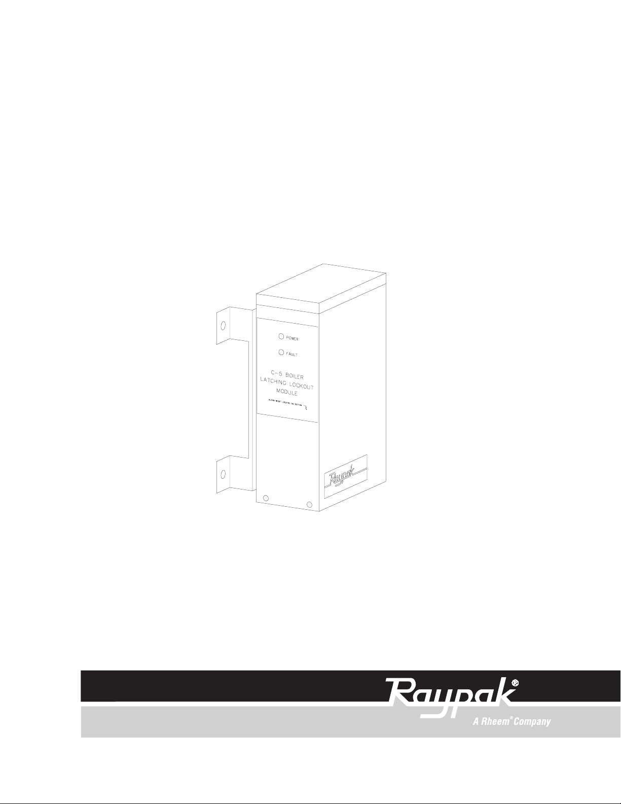
C-5 LATCHING LOCKOUT
MODULE
Installation and Operating Manual
PN 240722 Rev . 2
Page 2

C-5 LATCHING LOCKOUT MODULE
Installation and Operating Manual
Before operating this product, please read these instructions completely .
2
Page 3

TABLE OF CONTENTS
Contents Page
Safety Instructions 4
Getting Started 5
Introduction 5
Concept of Operation 5
Installation Ad Mounting 6
Mechanical Installation 6
Checking Power Source 7
Field Wiring Connection Points 8
Field Wiring Installation 9
Installation V erification Procedure 10
Power T est 10
Latching Fault Detector 10
Latching Fault Detector Lights 10
Page 4

LATCHING LOCKOUT MODULE
IMPORTANT SAFETY INSTRUCTIONS
IMPORT ANT NOTICE:
who are specifically trained and experienced in the installation of this type of equipment and
related system components. Installation and service personnel may be required by some states
to be licensed. If your state requires certification, be sure your contractor bears the appropriate
license. Only qualified persons shall attempt to repair this equipment. Repair must be according
to these instructions.
These instructions are intended for use by qualified personnel
WARNING: Improper installation, adjustment, alteration, service or maintenance may dam-
age the equipment, create a hazard resulting in asphyxiation, explosion, fire, electric shock,
personal injury or property damage, and will void the warranty .
CAUTION: MORE THAN ONE (1) SUPPLY SOURCE. THIS APPLIANCE HAS PROVI-
SIONS TO BE CONNECTED TO MORE THAN ONE (1) SUPPLY SOURCE. TO REDUCE
THE RISK OF ELECTRIC SHOCK, DISCONNECT
VICING.
ALL SUCH CONNECTIONS BEFORE SER-
CAUTION: RISK OF ELECTRIC SHOCK. MORE THAN ONE (1) DISCONNECT SWITCH
MA Y BE REQUIRED TO DE-ENERGIZE THE EQUIPMENT BEFORE SERVICING .
NOTE: Minimum 18 A WG , 105°C, stranded wire must be used for all low voltage (less than 30
volts) external connections to the unit. Solid conductors should not be used because they can
cause excessive tension on contact points. Install conduit as appropriate. All high voltage wires
must be the same size (105°C, stranded wire) as the ones on the unit or larger.
Please Register Now…
and receive the full privileges of a Raypak controls user. Simply complete and return the attached card. This
information helps us to access ordering information in case of loss, damage or theft. We will contact you in the
unlikely event that any adjustments or modifications are ever required for your unit.
4
Page 5

LATCHING LOCKOUT MODULE
GETTING STARTED
Thank you for selecting the Raypak C-5 Latching Lockout Module (LLM). It is our sincere hope that you will enjoy
it's outstanding design and ease of use.
INTRODUCTION
Latching Lockout Module is a solid state electronic ignition fault latching detector and indicator that has been
engineered to enhance safety , simplify troubleshooting and minimize equipment down time.
CONCEPT OF OPERATION
The Latching Lockout Module is a control device that requires local (within physical sight and sound of the affected
equipment) manual intervention by an operator or service technician to reset. It is designed to comply with the
requirements of CSD-1.
NOTE: this latching Fault Detector module will not reset if power to the device and/or boiler is interrupted
then restored.
Standard Indicator Light s:
Power Green, indicates power is available to the Latching Lockout Module.
Fault Red, (flashing) indicates a fault occurred and ignition is locked out.
Relay (internal) Red, (on board near relay) indicates relay is actuated.
Reset of Fault condition:
Reset A switch (closure) between Pins 1 and 2 of P2 can clear a
fault, all fault indications, and allow the ignition process to
resume. Without a reset the fault will be "remembered", even
in a power down condition.
5
Page 6

Optional Remote Alarm and Indicators
External Fault Indicator An LED can be installed between Pins 3 and 4 of Terminal P2 and
illuminate (flash) at another location when a fault occurs.
Contact Closure On Fault Provides dry contacts, between Pins 1 and 2 of P5, that close
when a fault has occurred.
INST ALLA TION AND MOUNTING
If the C-5 Latching Lockout Module was not installed on the boiler by the factory , care should be taken to select a
suitable mounting location for the enclosure. The C-5 Latching Lockout Module should be mounted on a solid and
permanent base on the side of the boiler.
MECHANICAL INSTALLATION
Install the Latching Lockout Module (LLM) on the side of the boiler(s). The Latching Lockout Module Fault
Detector must be mounted vertically with the conduit holes facing downward. The conduit holes are sized to
accommodate standard conduit fittings. If additional or larger conduit fittings are required, the holes should be
located on the bottom of the module.
Mount the Latching Fault Detector Module with the appropriate hardware in four (4) places.
A minimum of eighteen (18) inches clearance from the front, and six (6) inches clearance on all other sides is
required for service access.
An electrical distribution sub-panel containing appropriate disconnect switches and surge suppressor is required at
or near the equipment location (s).
INSTALL CONDUIT AS APPROPRIATE
Any wiring harnesses must be protected by conduit.
ELECTRICAL CHARACTERISTICS
C-5 Latching Lockout Module
Control Module - 24 V AC, 0.5A; 60Hz
ELECTRICAL INSTALLATION
24 V AC FEEDER CIRCUITS
Apply 24 V AC to Pins 1 and 3 of Terminal P1 to power Latching Lockout Module.
Note: 18 A WG - S tranded wire must be used for all connections to Printed Circuit Board (PCB).
Solid conductors should not be used because solid wire conductors can cause excessive tension on contact
points.
6
Page 7

CHECK YOUR POWER SOURCE
Using a volt-ohm meter, check the following volt ages at the circuit breaker panel:
AC = 108 Volt s AC Minimum, 132 Volts MAX
Hot to Ground (Black to Green)
AB = 108 Volt s AC Minimum, 132 Volts MAX
Hot to Neutral (Black to White)
BC = Must be less than 1.0 Volts AC
Neutral to Ground
(White to Green)
7
Page 8

FIELD WIRING CONNECTION POINTS
24 V AC RTN POWER IN
24 V AC
NO CONT ACT CLOSURE
W ON FAUL T
TH-W FROM: CENTRAL
24 VAC POINT WIRING
RTN BOARD
GND
PV
MV/PV
MV
TH-2 TO: IGNITION
24 VAC MODULE
RTN
GND
PV
MV/PV
MV
+ TO: REMOTE LED
- TO: SWITCH
Note: Tighten terminal strip clamping screws to 4 in-lbs. Breakage from over torquing is not covered under warranty .
Use 18 A WG stranded copper conductors only .
For supply connections, use wires sized on the basis of 60°C ampacity and rated a min. 90° (194°F)
8
Page 9

FIELD WIRING INSTALLATION
The C-5 Latching Lockout Module is installed in series between the Boiler Control and the ignition module.
Use Field Wring Connection Point diagram to aid in installation.
Remove the ignition connection pins below, cut of f the female spade lugs, strip back the wire 1/4 inch, and
install in connector P3 of the LLM board.
From: Color Name To:
Ignition Pin C-5, P3 Pin
1 Violet/Black MV 1
2 Yellow/Black MV/PV 2
3 Red/Black PV 3
4 GND 4
5 Y ellow 24 VAC (GND) 5
6 Blue 24 V AC (HOT) 6
Install wires (cut to appropriate length) between connector P4 of the Universal Wiring Module (U-1) and connector P4 of the LLM board.
From: Color Name To:
P4, Pin C-5, P4 Pin
1 Violet/Black MV 1
2 Yellow/Black MV/PV 2
3 Red/Back PV 3
4 GND 4
5 Y ellow 24 VAC (GND) 5
6 Blue 24 VAC (Hot) 6
Connect 24 V AC power to LLM board:
From: Color Name To:
boiler power C-5, P1 Pin
24 Hot Blue 24 Hot 1
24 Return Y ellow 24 Return 3
Connect reset switch (N/O):
From: Color To:
Switch C-5 LLM, P2 Pin
Wiper Yellow/Red 1
N/O Y ellow/Red 2
Remote LED: -Option
Connect remote LED
From: Color To:
LED LLM, P2 Pin
- Green/Yellow 3
+ Yellow/Red 4
Remote LED: -Option
Connect remote device to contact closure on fault, these dry contacts close on fault
From: Color To:
LED C-5, P5 Pin
Field Installation 1
Field Installation 2
Factory Installed Jumper
9
Page 10

INSTALLATION VERIFICATION PROCEDURE
REGISTER
Before proceeding any further, please verify that the user registration form has been completed and mailed.
MECHANICAL INSTALLATION
Verify that the mechanical installation has been completed in accordance with the instructions.
SYSTEM MODULE INSTALLATION
Verify electrical power wiring connections.
Verify electrical connection torque requirements.
Verify Power Test has been completed successfully.
POWER TEST
CHECK POWER
Utilizing a Volt-Ohm-Meter (VOM) monitor the following on the Boiler for proper voltage levels.
POWER TEST TABLE
From: To: Indication:
120 V AC HOT (BLACK) 120 V AC NEUTRAL (WHITE) 108 VAC T O 132 V AC
120 V AC HOT (BLACK) SINGLE POINT GROUND (SPG) 108 V AC TO 132 V AC
120 V AC NEUTRAL (WHITE) SINGLE POINT GROUND (SPG) less than 1 V AC
LATCHING FAUL T DETECTOR
MANUAL OVERRIDE
Internal Switch (S5) Output Override (reset switch) can be used to manually override the Micro-controller control
as long as the Electronic Boiler Control circuit board has 24 V AC power . See Reset of Fault condition.
Latching Fault Detector Lights
POWER
FAULT
INDICA TOR LIGHTS
RELAY (internal)
(Green) indicates that 24 V AC is being supplied to Latching Fault
Detector.
(Red) indicates a fault has occurred and ignition is locked out.
(Red, on board, inside) indicates relay is energized.
10
Page 11

CALL OUT DESCRIPTION PART NO.
A Kit Alarm Reset Switch 005641F
B Kit PC Board C5 Latching Lockout 006203F
11
Page 12

LIMITED WARRANTY
Latching Fault Detector & Accessories
SCOPE OF WARRANTY :
Raypak, Inc. ("Raypak") warrants to the original owner the Control System to be free from defects in materials and
workmanship under normal use and service for the applicable warranty period. In accordance with the terms of this Limited
Warranty, RAYPAK will furnish a replacement or repair, at our option, any defective part which fails in normal use and service
during the applicable warranty period. The replacement or repair will be warranted for only the unexpired portion of the original
Warranty Period.
APPLICABLE WARRANTY PERIOD
The effective date of warranty coverage is the date of original installation, of the Control System, by a qualified electrician
or by a RAYPAK authorized service technician. The Applicable Warranty Period is one (1) year from the effective date.
WARRANTY EXCLUSIONS
This Limited Warranty does not apply:
1. if the control system is not properly installed by a qualified technician in accordance with manufacturer's installation
instructions, applicable codes, ordinances and good trade practices,
2. to damage or malfunctions resulting from failure to properly install, operate or maintain the system in accordance
with the manufacturer's instructions;
3. if the rating plate(s) or serial number(s) are altered, defaced or removed;
4. if the System is modified in any way or used with any non-factory authorized accessories or components;
5. to damage or failure from abuse, accident, act of nature, fire, flood, freezing or the like;
6. to accessories, rubber or plastic parts, light bulbs or glass parts;
7. if the System is moved from its original installation site; or if the original owner no longer owns the site or the System.
LABOR AND SHIPPING COSTS
This Limited Warranty does not cover labor costs for service, removal or reinstallation of any part nor shipping charges
to or from RAYPAK'S designated repair center or to or from the installation site. All such costs are your responsibility.
HOW TO MAKE A WARRANTY CLAIM
To make a warranty claim, promptly ship (postage prepaid) or carry the defective part to a designated RAYPAK
Service Dealer or Service Station in the United States, supplying proof of purchase and date of installation and the model and
serial numbers. If you cannot locate a dealer, contact RAYPAK'S Service Department at the address/telephone listed below.
Raypak reserves the right at all times to inspect the claimed defect and verify warranty coverage at its factory.
EXCLUSIVE WARRANTY - LIMITATION OF LIABILITY
This is the only warranty given by RAYPAK. No one is authorized to make any other warranties on Raypak's behalf.
ANY IMPLIED WARRANTIES, INCLUDING MERCHANTABILITY OR FITNESS FOR A PARTICULAR PURPOSE, SHALL NOT
EXTEND BEYOND THE APPLICABLE WARRANTY PERIOD SPECIFIED ABOVE. RAYPAK'S SOLE LIABILITY WITH RESPECT TO
ANY DEFECT SHALL BE AS SET FORTH IN THIS LIMITED WARRANTY. ANY CLAIMS FOR INCIDENTAL OR CONSEQUENTIAL
DAMAGES (INCLUDING DAMAGE FROM WATER LEAKAGE) ARE EXCLUDED. Some states do not allow limitations on how long
an implied warranty lasts, or for the exclusion of incidental or consequential damages, so the above limitation or exclusion
may not apply to you.
THIS LIMITED WARRANTY GIVES YOU SPECIFIC LEGAL RIGHTS, AND YOU MAY ALSO HAVE OTHER RIGHTS
WHICH VARY FROM STATE TO STATE.
We suggest you immediately complete the information below and retain this Limited Warranty Certificate in case warranty
service is needed. RAYPAK, INC. SERVICE DEPARTMENT
2151 Eastman Ave, Oxnard, California 93030
Telephone: (805) 278-5300 FAX (805) 278-5489
The following information must be provided when you write or call:
_______________________________________________________________________________________________
Original Owner Daytime Telephone Number
__________________________________________________________________________________________________
Complete Mailing Address
_______________________________________________________________________________________________
City State Zip Code Installation Site
_______________________________________________________________________________________________
Model Number Contractor/Installer
_______________________________________________________________________________________________
Date of Installation Serial Number
Raypak, Inc., 2151 Eastman Ave, Oxnard, CA 93030 (805) 278-5300 FAX (805) 278-5489 Litho in U.S.A.
Page 13

www.raypak.com
Raypak, Inc., 2151 Eastman Ave., Oxnard, CA 93030 (805) 278-5300- Fax (805) 278-5489
Litho in U.S.A.
 Loading...