

Page 1
ATMOSPHERIC
Hot Water Dispenser
AWD-12 Series
Installation &
Operating Manual
I&W #07.05.126.00
This manual contains important safety information
concerning the maintenance, use and operation
of this product. Failure to follow the instructions
contained in this manual may result in serious
injury. If you are unable to understand the
contents of this manual, please bring it to the
attention of your supervisor. Do not operate this
equipment unless you have read and understood
the contents of this manual.
Este manual contiene importante información
sobre seguridad concerniente al mantenimiento,
uso y operación de este producto. Cualquier
falla en el seguimiento de las instrucciones
contenidas en este manual puede resultar
en un serio daño. Si usted no puede entender
el contenido de este manual por favor pregunte
a su supervisor. No opere este equipo al menos
que haya leído y comprendido el contenido
de este manual.
Page 2
are factory-assembled and ready for installation.
This manual provides the installation, safety
and operating instructions for the Atmospheric Hot
Water Dispensers. We recommend all installation,
operating and safety instructions appearing in this
manual be read prior to installation or operation
of your Hatco Atmospheric Hot Water Dispenser.
Safety instructions that appear in this manual after
a warning symbol and the words WARNING
or CAUTION printed in bold face are very
important. WARNING means there
is the possibility of serious injury or death
to yourself or others. CAUTION means there
is the possibility of minor or moderate injury.
CAUTION without the symbol signifies the
possibility of equipment or property damage only.
Hatco Atmospheric Hot Water Dispensers
are a product of extensive research and field
testing. The materials used were selected
for maximum durability, attractive appearance
and optimum performance. Every unit is thoroughly
inspected and tested prior to shipment.
i
INTRODUCTION
Hatco Atmospheric Hot Water Dispensers are
designed to deliver pre-measured quantities
of hot water for food preparation or cleaning.
A 12 gallon (45 liter) stainless steel tank provides
up to 8 gallons (30 liters) of continuous,
temperature controlled water ranging from
75°–195°F (24°–91°C). The tank may be emptied
easily using the convenient bottom drain.
Hatco Atmospheric Hot Water Dispensers design
features include an electronic temperature
controller with a digital temperature display, On/Off
switch, preset dispenser pushbuttons, including
a manual dispense function.
Standard equipment includes a stainless steel
base, a white granite powder coated body,
4" (10 cm) legs and a 6' (2 mm) electrical cord
and plug. All electric heating elements are metal
sheathed and controlled by a submersed
thermistor. The units are protected with a hightemperature limit switch and low-water cutoff.
The unit electrical and plumbing connections
CONTENTS
Important Owner Information...............................i
Introduction ...........................................................i
Important Safety Instructions.............................1
Model Descriptions..............................................2
All Models........................................................2
Specifications.......................................................2
Plug Configurations.........................................2
Electrical Rating Chart ....................................3
Dimensions......................................................3
Statistics..........................................................3
Installation............................................................4
Location...........................................................4
Plumbing .........................................................4
Electrical..........................................................4
Operation..............................................................5
Start-Up...........................................................5
Dispensing Hot Water.....................................5
Error Codes.....................................................6
Programming the Dispenser ...........................6
Maintenance .........................................................8
General............................................................8
Cleaning Dispenser Exterior ...........................8
Draining the Dispenser....................................8
De-Liming the Dispenser.................................8
Resetting the High Temperature Safety Switch...9
Hatco Limited Warranty.....................................10
Authorized Parts Distributors............Back Cover
IMPORTANT OWNER INFORMATION
Record the model number, serial number
(identification decal located on the lower side
of the unit), voltage and purchase date of your
Atmospheric Hot Water Dispenser in the spaces
below. Please have this information available when
calling Hatco for service assistance.
Model No. ________________________________
Serial No. ________________________________
Voltage __________________________________
Date of Purchase __________________________
Business 8:00 a.m. to 5:00 p.m.
Hours: Central Standard Time
(Summer Hours: June to September –
8:00 a.m. to 5:00 p.m. C.D.T.
Monday through Thursday
8:00 a.m. to 2:30 p.m. C.D.T. Friday)
Telephone: (800) 558-0607; (414) 671-6350
Fax: (800) 690-2966 (Parts & Service)
(414) 671-3976 (International)
Additional information can be found by visiting our
web site at www.hatcocorp.com
Form No. AWDM-0704
24-Hour 7-Day Parts & Service
Assistance available in the
United States and Canada
by calling (800) 558-0607.
Page 3
CAUTIONS
Locate the dispenser at the proper counter
height, in an area that is convenient
for use. The location should be level
to prevent the unit or its contents from
accidentally falling, and strong enough
to support the weight of the unit
and water supplied.
Unit is not weatherproof. For safe and proper
operation locate the unit indoors where
the ambient air temperature is a minimum
of 70°F (21°C).
To assure proper operation and to avoid
damage to the unit, the incoming water
supply pressure must be at least 35 psi
(241 kPa) and not exceed 80 psi (552 kPa).
To assure proper operation and to avoid
damage to the unit, the incoming water
supply temperature must not exceed
140°F (60°C).
CAUTIONS
The unit must be transported in an upright
position. If laid on its side, the water must
be drained from the unit.
Do not use deionized water. Deionized water
will greatly shorten the life of the water
heating elements and plumbing components.
Water Quality Requirements – Incoming
water in excess of 3.0 grains of hardness
per gallon (GPG) (.75 grains of hardness
per liter) must be treated and softened before
being supplied to an Atmospheric Hot Water
Dispenser. Water containing over 3.0 GPG
(.75 GPL) will decrease the efficiency
and reduce the operating life of the unit.
Do not overtighten plumbing connections.
Overtightening may cause leaks.
IMPORTANT SAFETY INSTRUCTIONS
1
WARNINGS
Plug unit into a properly grounded electrical
outlet of the correct voltage, size and plug
configuration. If the plug and receptacle
do not match, contact a qualified electrician
to determine the proper voltage and size
and install the proper electrical outlet.
To avoid any injury, turn the power switch
off at the fuse disconnect switch/circuit
breaker or unplug the unit from the power
source and allow to cool completely before
performing any maintenance or cleaning.
To avoid any injury, turn the power off to the
unit and allow to cool before draining.
To avoid any injury or damage to the unit
do not pull unit by power cord.
To prevent any injury, discontinue use
if power cord is frayed or worn.
For proper plumbing installation conforming
to local plumbing codes, consult a licensed
plumbing contractor.
Water dispensed is very HOT. Use proper
container for holding hot water.
If service is required on this unit, contact your
Authorized Hatco Service Agent, or contact
the Hatco Service Department at 800-558-0607
or 414-671-6350; fax 800-690-2966
or international fax 414-671-3976.
This product has no “user” serviceable
parts. To avoid damage to the unit or injury
to personnel, use only Authorized Hatco
Service Agents and Genuine Hatco Parts
when service is required.
Genuine Hatco Replacement Parts
are specified to operate safely in the
environments in which they are used. Some
aftermarket or generic replacement parts
do not have the characteristics that will allow
them to operate safely in Hatco equipment. It
is essential to use Hatco Replacement Parts
when repairing Hatco equipment. Failure
to use Hatco Replacement Parts may subject
operators of the equipment to hazardous
electrical voltage, resulting in electrical
shock or burn.
Form No. AWDM-0704
IMPORTANT! Read the following important safety instructions to avoid personal injury
or death, and to avoid damage to the equipment or property.
Page 4
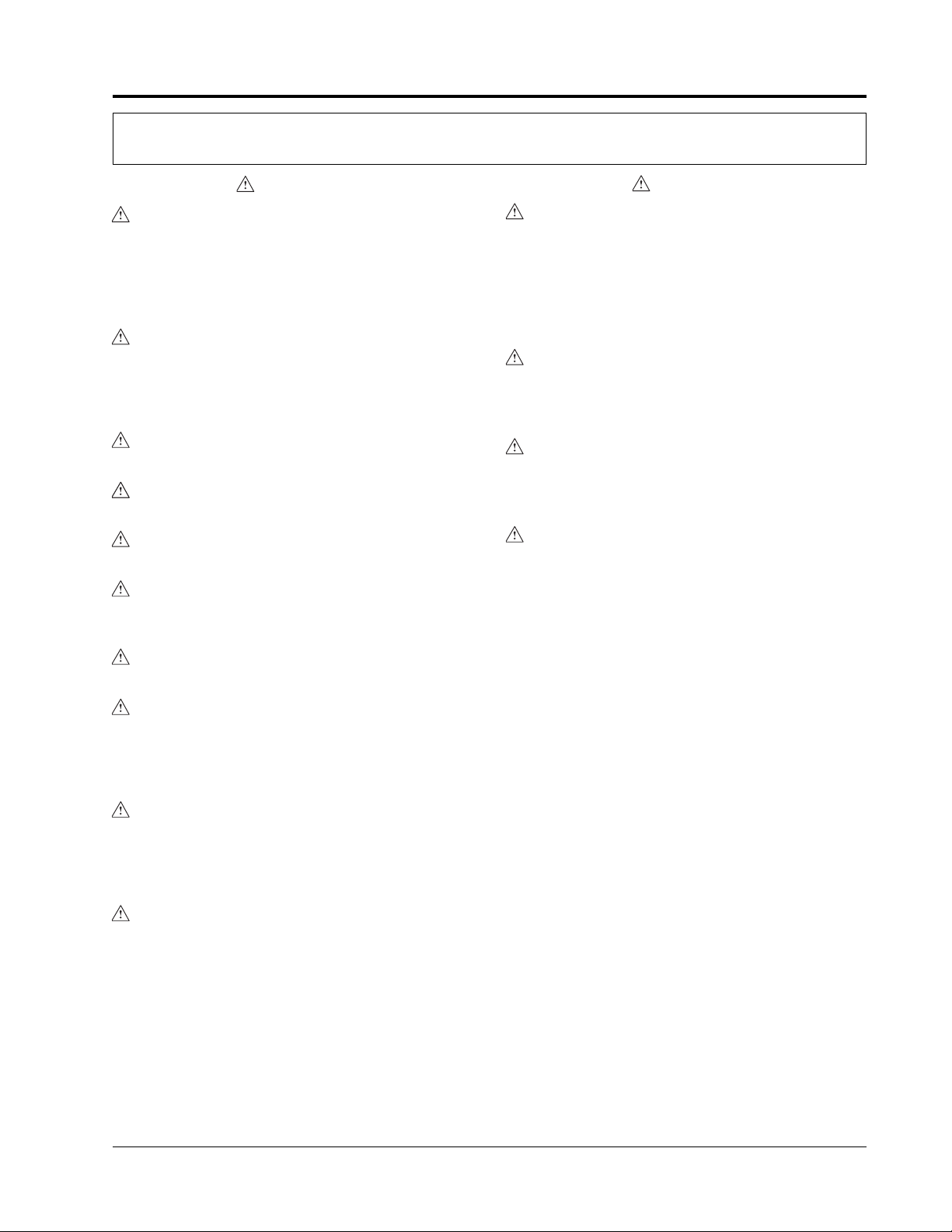
MODEL DESCRIPTIONS
2
ALL MODELS
Hatco Atmospheric Hot Water Dispensers
are equipped with an electronic temperature
controller, an On/Off switch, a digital temperature
display, preset dispensing push-buttons, including
a manual dispense function. Electric heating
elements are metal sheathed and controlled
by a submersed thermistor. The units are protected
with a high-temperature limit switch and low-water
cut-off.
Standard equipment includes a stainless steel
base, a white granite powder coated body,
4" (102 mm) legs, tank drain and a 6' (2 m)
electrical cord and plug.
A 12 gallon (45 liter) stainless steel tank provides
up to 8 gallons (30 liters) of continuous,
temperature controlled water ranging from
75°-195°F (24°-91°C).
Figure 1. Model AWD-12
Form No.
AWDM-0704
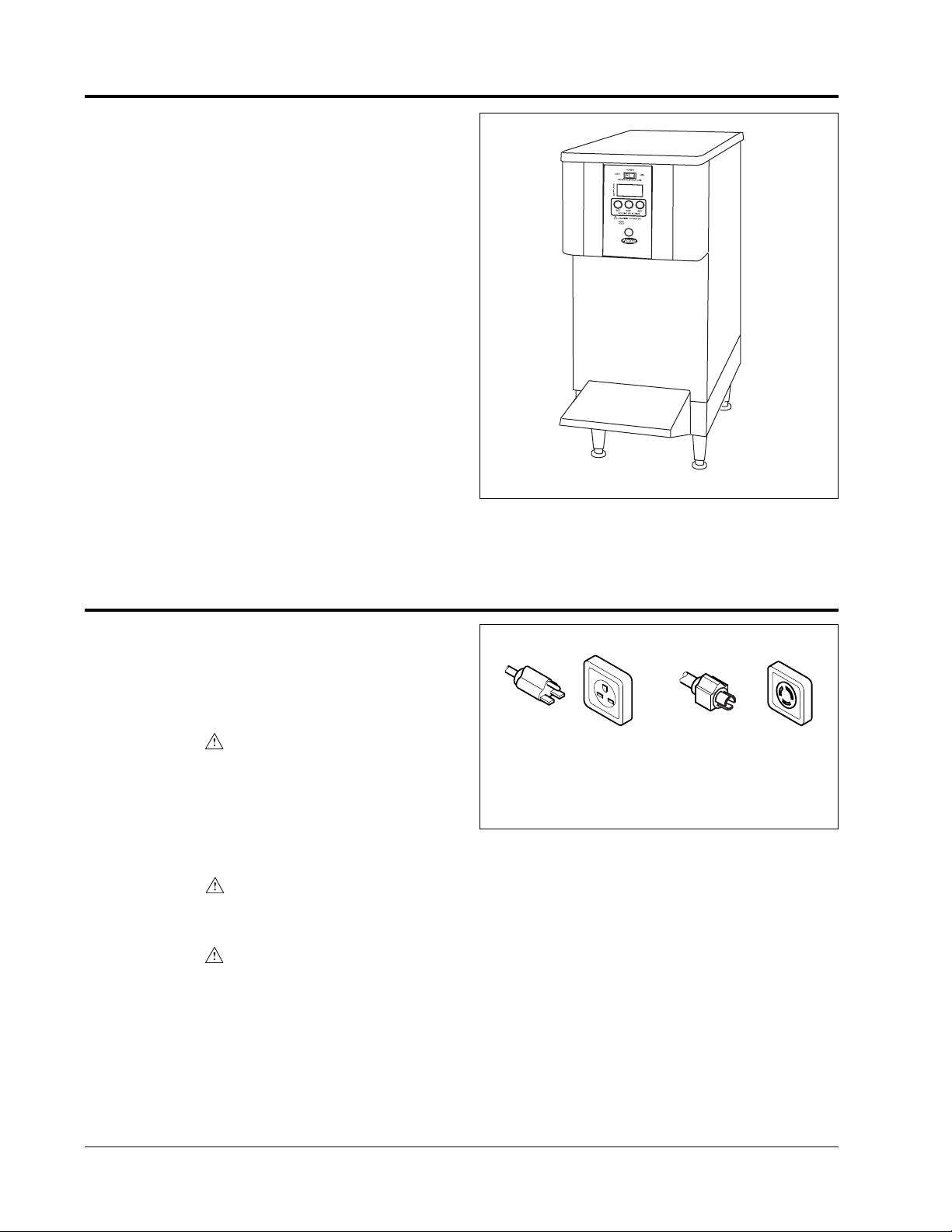
SPECIFICATIONS
NEMA 6-30P
NEMA L6-30P
*
*NEMA L6-30P is a locking plug available as a
factory installed option.
Figure 2. Plug Configurations
PLUG CONFIGURATIONS
Units are supplied from the factory with
an electrical cord and plug installed. Plugs
are supplied according to the applications
as shown in Figure 2.
WARNING
Plug unit into a properly grounded electrical
outlet of the correct voltage, size and plug
configuration. If the plug and receptacle
do not match, contact a qualified electrician
to determine the proper voltage and size
and install the proper electrical outlet.
WARNING
To avoid any injury or damage to the unit
do not pull unit by power cord.
WARNING
To prevent any injury, discontinue use if power
cord is frayed or worn.
Page 5
SPECIFICATIONS
3
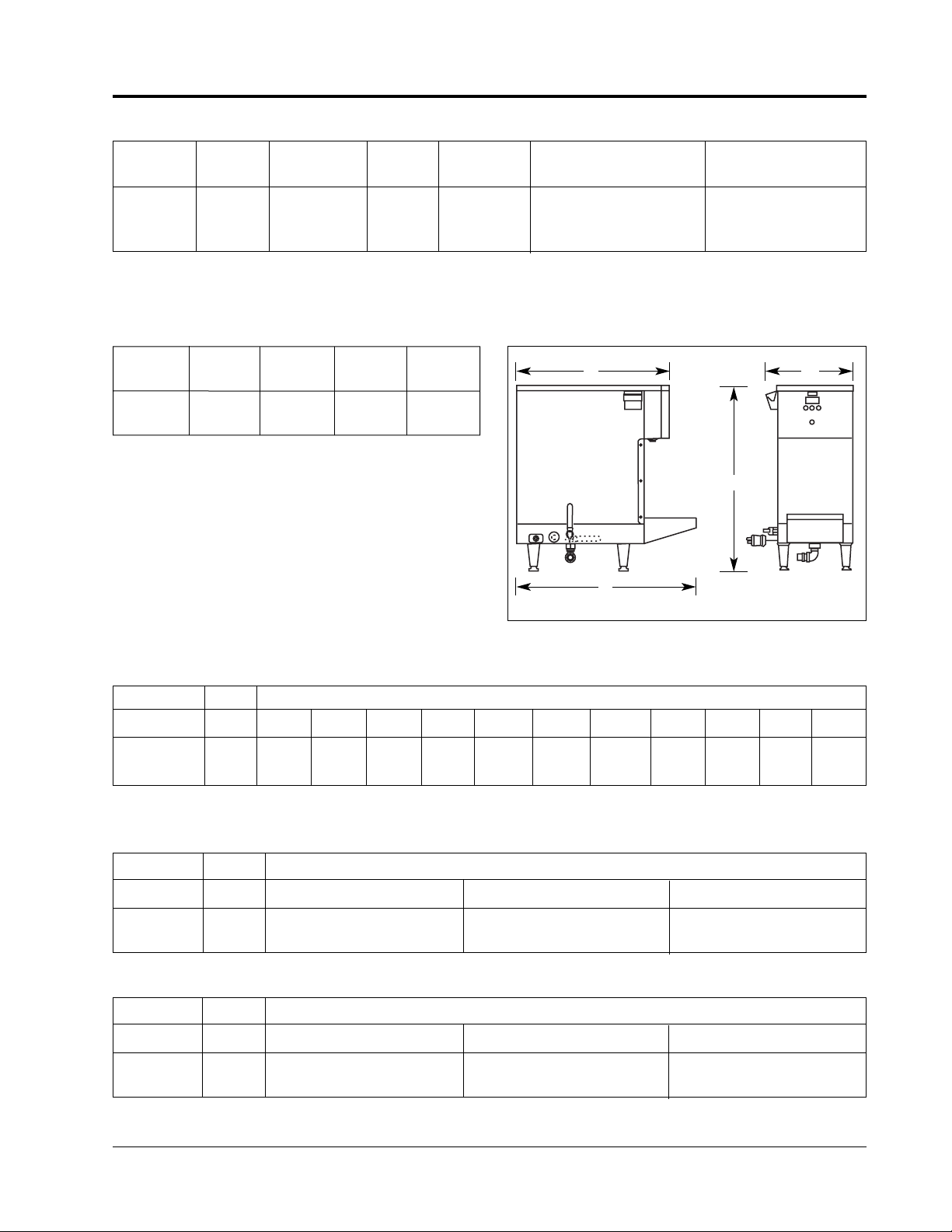
Figure 3. Dimensions
Form No. AWDM-0704
Kilowatts
Model Voltage (kW) Phase Amps Plug Configuration Shipping Weight†
AWD-12 208 5 1 24.0 NEMA 6-30P
*
80 lbs. (36 kg)
240 5 1 20.8 NEMA 6-30P
*
80 lbs. (36 kg)
ELECTRICAL RATING CHART
* NEMA L6-30P is optional
DIMENSIONS
WATER TEMPERATURE RECOVERY TABLE
COLD-START HEAT-UP TIME
Width Depth Depth Height
Model (A) (B) (C) (D)
AWD-12 13-3/8" 23-1/2" 27-1/2" 28-1/8"
(340 mm) (597 mm) (699 mm) (714 mm)
C
B
D
A
† Unit weight, filled to 12 gallon (45 liters) capacity is 180 lbs. (82 kg).
Model kw Degrees of Rise
60°F 70°F 80°F 90°F 100°F 110°F 120°F 130°F 140°F 150°F 160°F
AWD-12 5 33 gph 29 gph 25 gph 22 gph 20 gph 18 gph 17 gph 15 gph 14 gph 13 gph 12 gph
Model kw Degrees of Rise
60°F 90°F 140°F
AWD-12 5 22 Minutes 33 Minutes 52 Minutes
WATER TEMPERATURE RECOVERY TIME
Model kw Degrees of Rise
60°F 90°F 140°F
AWD-12 5 15 Minutes* 22 Minutes* 35 Minutes*
* Recovery times are after 9.75 gallons of water have been dispensed.
NOTE: gph is gallons per hour.
Page 6

INSTALLATION
4
Form No.
AWDM-0704
LOCATION
CAUTION
The unit must be transported in an upright
position. If laid on its side, the water must
be drained from the unit.
WARNING
To avoid any injury or damage to the unit
do not pull unit by power cord.
CAUTION
Unit is not weatherproof. For safe and proper
operation locate the unit indoors where
the ambient air temperature is a minimum
of 70°F (21°C).
CAUTION
Locate the dispenser at the proper counter
height, in an area that is convenient for use.
The location should be level to prevent
the unit or its contents from accidentally falling,
and strong enough to support the weight
of the unit and water supplied.
PLUMBING
WARNING
For proper plumbing installation conforming
to local plumbing codes, consult a licensed
plumbing contractor.
CAUTION
Water Quality Requirements – Incoming water
in excess of 3.0 grains of hardness per gallon
(GPG) (.75 grains of hardness per liter) must
be treated and softened before being supplied
to an Atmospheric Hot Water Dispenser.
Water containing over 3.0 GPG (.75 GPL)
will decrease the efficiency and reduce
the operating life of the unit.
CAUTION
Do not overtighten plumbing connections.
Overtightening may cause leaks.
CAUTION
Do not use deionized water. Deionized water
will greatly shorten the life of the water heating
elements and plumbing components.
1. Connect a flexible water supply line to the inlet
on the unit using 1/4" NPT adapter with flare
connection (or by using optional 1/4" inlet tubing
supplied by Hatco). See Figure 4.
NOTE: Water inlet and drain connections must
be made with flexible hose.
CAUTION
To assure proper operation and to avoid
damage to the unit, the incoming water supply
pressure must be at least 35 psi (241 kPa)
and not exceed 80 psi (552 kPa).
Figure 4. Plumbing for AWD-12
CAUTION
To assure proper operation and to avoid
damage to the unit, the incoming water supply
temperature must not exceed 140°F (60°C).
NOTE: If required, a ball valve or gate valve, line
strainer, union(s) and vacuum breaker or other
anti-siphon device must be supplied by plumber
or installer.
2. Tighten connections securely.
3. Turn on water supply and check for leaks.
A drain connection is located under the unit
for manually draining the dispenser. A male hose
connector is included. See MAINTENANCE
for draining information.
NOTE: A 3/4" (19 mm) flexible hose may
be connected to the heater sump drain and run
to an open sight drain. See Figure 4. The sump
drain should not be permanently connected
to the sanitary drain system. Check local plumbing
code for proper drain installation.
ELECTRICAL
WARNING
Plug unit into a properly grounded electrical
outlet of the correct voltage, size and plug
configuration. If the plug and receptacle
do not match, contact a qualified electrician
to determine the proper voltage and size
and install the proper electrical outlet.
Gate or Ball
Valve
Water
Inlet
Page 7

OPERATION
5
Form No. AWDM-0704
Figure 5. Control Panel
Figure 6. Removing/Installing Shelf
START-UP
NOTE: Make sure manual drain lever
is in the horizontal (closed) position. See Figure 9.
1. Place power switch in the ON position
The electronic display will light up to indicate
power is supplied to the unit. See Figure 5.
2. The display will show E3 indicating that
the heating elements are not yet submersed
(water should be filling the tank at this point).
3. When the tank water level reaches the low
water probe the display will show the current
water temperature and a small red light will
glow in the upper left-hand corner of the display
indicating that the heating elements
are energized.
4. Water will continue to fill the tank until the upper
water probe has been satisfied and the heating
elements will remain on until tank water reaches
the programmed temperature setpoint.
5. When the display shows the desired water
temperature, generally 195°F (91°C), the unit
is ready to dispense water.
NOTE: A temperature setting higher than
195°F (91°C) may cause nuisance tripping
of the high limit switch and is not recommended.
If temperature adjustments are required see
PROGRAMMING THE DISPENSER. To reset
the high limit switch, see RESETTING THE HIGH
TEMPERATURE LIMIT SWITCH.
NOTE: If temperature adjustments are required
see PROGRAMMING THE DISPENSER.
DISPENSING HOT WATER
WARNING
Water dispensed is very HOT. Use proper
container for holding hot water.
Place the proper water container for holding hot
water on the shelf before dispensing.
The shelf can be removed to dispense water
into containers larger than the space between
the dispenser and shelf. Lift shelf up and off
the mounting screwheads to remove shelf.
See Figure 6.
Dispensing is controlled by the four dispense
buttons on the front of the unit. See Figure 5.
• The three buttons underneath the LED display
dispense at pre-programmed quantities of 2QT,
3QT & 4QT as marked.
2QT = 2 quarts (1.9 liters)
3QT = 3 quarts (2.8 liters)
4QT = 4 quarts (3.8 liters)
NOTE: The dispense amounts can be adjusted if
required. See PROGRAMMING THE DISPENSER.
• The red button can be pressed any time
after pressing one of the programmed dispense
buttons to stop dispensing.
In addition, the red button can be pressed
and held in to manually dispense water.
Water will continue to flow until the red button
is released.
Auto Stop/Manual
Dispense Button
Page 8

ERROR CODES
There are four error codes that may show
in the display:
E1: Indicates that the display temperature
is out of range or display temperature probe
is malfunctioning.
E2: Indicates that the control temperature
is out of range or control temperature probe
is malfunctioning.
E3: Indicates that the low water probe
has not been satisfied. The heating elements
are not yet submersed.
H2O: Indicates that the inlet water solenoid has
been running continuously for an excessive
period of time. Check for problems with
the water supply or internal water leak.
PROGRAMMING THE DISPENSER
WARNING
To avoid any injury, turn the power switch
off at the fuse disconnect switch/circuit breaker
or unplug the unit from the power source
and allow to cool completely before performing
any maintenance or cleaning.
Dipswitch Panel
A dipswitch panel is located on the back
of the control board which is behind the front
panel graphic overlay. The switches have
the following functions:
Switch 1 is used to switch between operational
(Run) mode and Programming mode.
Switch 2 is used to change the temperature
display from F° to C°.
Switch 3 is used to select the type of operation,
and must be switched to the right-hand position
for the dispenser to operate.
Switch 4 is not used.
Changing Temperature Display
1. Turn the power switch to the OFF position
and unplug the unit from the electrical outlet.
2. Remove top red panel.
3. Move dipswitch 2 to the left, (when facing
the controls) to change the display from
Fahrenheit (F°) to Celsius (C°).
4. Re-install top red panel.
5. Plug the unit into the proper electrical outlet
and turn the power switch to ON.
OPERATION
6
Form No.
AWDM-0704
Figure 7. Setting Temperature Setpoint
Changing Temperature Setpoint
1. Turn the power switch to the OFF position
and unplug the unit from the electrical outlet.
2. Remove top red panel.
3. Move dipswitch 1 to the left, (when facing
the controls) to enter programming mode.
4. Plug the unit into the proper electrical outlet
and turn the power switch to ON.
The LED will display (temperature setpoint).
This indicates the beginning of the programming
sequence. Press the RED manual dispense button
and the display will now read the current
temperature setpoint. See Figure 7.
5. Use the 2QT and 3QT buttons to adjust
the temperature setpoint up or down.
6. When the desired setpoint is displayed, press
the RED dispense button to save the change
to memory. Turn the power switch to OFF
and unplug the unit from the electrical outlet.
NOTE: If no buttons are pressed for a period
of 15 seconds, the program will automatically
jump to the end of the programming sequence,
and the display will read END.
7. Move dipswitch 1 back to the operational
(Run) mode.
8. Re-install top red panel.
9. Plug the unit into the proper electrical outlet
and turn the power switch to ON.
Adjustable from 75° - 195°F (82° - 91°C)
in 1 degree intervals.
'#
Page 9

OPERATION
7
Form No.
AWDM-0704
Figure 8. Setting Dispenser Time -
2QT Dispenser Shown
Changing Dispense Time (Water quantity)
1. Turn the power switch to the OFF position
and unplug the unit from the electrical outlet.
2. Remove top red panel.
3. Move dipswitch 1 to the left, (when facing
the controls) to enter Programming mode.
4. Plug the unit into the proper electrical outlet
and turn the power switch to ON.
The LED will display (temperature
setpoint). This indicates the beginning
of the programming sequence.
5. Press the RED manual dispense button
to scroll to the desired dispenser button
to be programmed. See Figure 8.
NOTE: Dispenser button 1 = 2QT
Dispenser button 2 = 3QT
Dispenser button 3 = 4QT
6. Use the 2QT and 3QT buttons to adjust
the dispense time up or down.
7. When the desired dispense time is displayed,
press the RED button to save the change
to memory and to scroll to the next desired
dispense button. Repeat step 6 or turn
the power switch to OFF and unplug the unit
from the electrical outlet.
8. Move dipswitch 1 back to the operational
(Run) mode.
9. Re-install top red panel.
10.Plug the unit into the proper electrical outlet
and turn the power switch to ON.
Adjustable from 0 - 120 seconds
in 1 second intervals.
Page 10

8Form No. AWDM-0704
MAINTENANCE
NOTE: It is recommended that this procedure
be performed when the dispenser will not be used
for a period of time, such as at the end of the day.
1. With the unit at operating temperature of 195°F
(91°C), turn the power switch OFF and drain
3 gallons (11 liters) of water through the manual
drain (see DRAINING THE DISPENSER).
2. Replace the drained 3 gallons (11 liters) with
3 gallons (11 liters) of off-the-shelf vinegar.
Slowly pour the vinegar into the black fill cup
on the upper side of the unit. See Figure 9.
3. Turn the power switch ON and allow the unit
to heat up to the operating temperature
generally 195°F (91°C). Run the unit at this
temperature for 1-2 hours.
4. Dispense 1/2 quart (.4 liters) of solution through
the dispensing port. This exposes the port
to the de-liming agent. (Safely discard
dispensed solution.)
5. Turn power OFF to unit and allow de-liming
agent to remain in unit for a minimum
of 4 hours. (Preferably overnite.)
6. After the de-liming period, drain the solution
from the tank. (See DRAINING
THE DISPENSER.)
GENERAL
WARNING
To avoid any injury, turn the power switch
off at the fuse disconnect switch/circuit breaker
or unplug the unit from the power source
and allow to cool completely before performing
any maintenance or cleaning.
CLEANING DISPENSER EXTERIOR
To preserve the finish of the Atmospheric Hot
Water Dispenser, it is recommended that
the exterior surfaces be wiped daily with
a clean, damp cloth.
DRAINING THE DISPENSER
It is recommended that the dispenser be drained
prior to moving the unit and after performing
the De-Liming the Dispenser.
WARNING
To avoid any injury, turn the power off to the
unit and allow to cool before draining.
1. Shut off the water supply to the unit.
2. Turn the power switch to the OFF position
and unplug the unit from the electrical outlet.
3. Connect drain hose to water outlet on underside
of unit. See Figure 9.
4. Place open end of drain hose in a bucket
or open site drain, in a manner according
to local plumbing codes.
5. Open the drain valve by placing the drain
handle in the vertical position. See Figure 9.
6. After water is through draining, place the valve
handle in the fully horizontal position to close
the valve. See Figure 9.
7. Turn on the water supply to the dispenser.
8. Plug the unit into the proper electrical outlet
and turn the power switch to ON.
DE-LIMING THE DISPENSER
A mixture of off-the-shelf vinegar (5% vinegar
solution) and water should be used to de-lime
the Atmospheric Water Dispenser. A minimum
mixture of 25% off-the-shelf vinegar and 75%
water is recommended to effectively de-lime
the dispenser.
NOTE: The lime and mineral content of the supply
water will determine how often this procedure must
be performed.
Figure 9. De-Liming the Unit
De-liming
Additive Fill
Cup
Page 11

Form No.
AWDM-07049
MAINTENANCE
WARNING
If service is required on this unit, contact your
Authorized Hatco Service Agent, or contact
the Hatco Service Department at 800-558-0607
or 414-671-6350; fax 800-690-2966
or international fax 414-671-3976.
WARNING
This product has no “user” serviceable parts.
To avoid damage to the unit or injury
to personnel, use only Authorized Hatco
Service Agents and Genuine Hatco Parts when
service is required.
WARNING
Genuine Hatco Replacement Parts are specified
to operate safely in the environments in which
they are used. Some aftermarket or generic
replacement parts do not have the
characteristics that will allow them to operate
safely in Hatco equipment. It is essential
to use Hatco Replacement Parts when repairing
Hatco equipment. Failure to use Hatco
Replacement Parts may subject operators
of the equipment to hazardous electrical
voltage, resulting in electrical shock or burn.
7. Refill the unit with water by following
the START-UP procedure. Continue to dispense
water out of the unit until the discharge is clear
and all de-liming solution has been removed
and rinsed.
NOTE: Steps 6 and 7 may need to be repeated
until all de-liming agent has been removed.
RESETTING THE HIGH TEMPERATURE
SAFETY SWITCH
The Atmospheric Water Dispenser is equipped
with a manually resettable high limit safety switch
that prevents the water temperature from getting
dangerously high. If the water inside the unit
exceeds 200°F (93°C) the safety high limit switch
will shut the unit off. Setting the setpoint
temperature over 195°F (91°C) may cause
nuisance tripping of this safety switch. Hatco does
not recommend adjusting the setpoint temperature
above 195°F (91°C).
To reset the safety high limit switch follow these
steps:
1. Turn the power switch OFF, unplug the unit
from the power source and allow to cool
completely before proceeding. The high limit
switch cannot be reset until the water
temperature drops below 150° (66°C).
2. Remove the front shelf and the six screws
that hold the front panel in place, then remove
the front panel.
3. The high limit safety switch is located
on the water tank, near the left heating element
(when facing controls) and the bottom
of the tank. To reset, press in the small red
button on the switch until it clicks.
4. Reinstall the front panel and shelf.
NOTE: If the high limit safety continues
to trip verify the setpoint is 195°F (91°C) or lower.
If the temperature setpoint is above 195°F (91°C)
adjust the setpoint down to an acceptable level.
See PROGRAMMING THE DISPENSER
for adjustment instructions. Contact an Authorized
Service Agent if the high limit safety continues
to trip and the temperature setpoint is 195°F (91°C)
or below.
Page 12

Form No. AWDM-0704 10
HATCO LIMITED WARRANTY
1. PRODUCT WARRANTY
Hatco warrants the products that it manufactures
(the “Products”) to be free from defects
in materials and workmanship, under normal
use and service, for a period of one (1) year
from the date of purchase when installed
and maintained in accordance with Hatco’s
written instructions or 18 months from the date
of shipment from Hatco. Buyer must establish
the product’s purchase date by returning Hatco’s
Warranty Registration Card or by other means
satisfactory to Hatco in its sole discretion.
Hatco warrants the following Product
components to be free from defects in materials
and workmanship from the date of purchase
(subject to the foregoing conditions)
for the period(s) of time and on the conditions
listed below:
a) One (1) Year Parts and Labor PLUS One
(1) Additional Year Parts-Only Warranty:
Toaster Elements (metal sheathed)
Drawer Warmer Elements (metal sheathed)
Drawer Warmer Drawer Rollers and Slides
Food Warmer Elements (metal sheathed)
Display Warmer Elements
(metal sheathed air heating)
Holding Cabinet Elements
(metal sheathed air eating)
b) One (1) Year Parts and Labor PLUS Four
(4) Years Parts-Only Warranty on
pro-rated terms that Hatco will explain
at Buyer’s request:
3CS and FR Tanks
c) One (1) Year Parts and Labor PLUS Nine
(9) Years Parts-Only Warranty on:
Electric Booster Heater Tanks
Gas Booster Heater Tanks
THE FOREGOING WARRANTIES ARE
EXCLUSIVE AND IN LIEU OF ANY OTHER
WARRANTY, EXPRESSED OR IMPLIED,
INCLUDING BUT NOT LIMITED TO ANY
IMPLIED WARRANTY OF MERCHANTABILITY
OR FITNESS FOR APARTICULAR PURPOSE
OR PATENT OR OTHER INTELLECTUAL
PROPERTY RIGHT INFRINGEMENT. Without
limiting the generality of the foregoing, SUCH
WARRANTIES DO NOT COVER: Coated
incandescent light bulbs, fluorescent lights, lamp
warmer heat bulbs, glass components, Product
failure in booster tank, fin tube heat exchanger,
or other water heating equipment, caused
by liming, sediment buildup, chemical attack
or freezing, Product misuse, tampering
or misapplication, improper installation
or application of improper voltage.
2. LIMITATION OF REMEDIES AND
DAMAGES
Hatco’s liability and Buyer’s exclusive remedy
hereunder will be limited solely, at Hatco’s
option, to repair or replacement by a Hatcoauthorized service agency (other than where
Buyer is located outside of the United States,
Canada, United Kingdom or Australia in which
case Hatco’s liability and Buyer’s exclusive
remedy hereunder will be limited solely
to replacement of part under warranty) with
respect to any claim made within the applicable
warranty period referred to above. Hatco
reserves the right to accept or reject any such
claim in whole or in part. Hatco will not accept
the return of any Product without prior written
approval from Hatco, and all such approved
returns shall be made at Buyer’s sole expense.
HATCO WILL NOT BE LIABLE, UNDER ANY
CIRCUMSTANCES, FOR CONSEQUENTIAL
OR INCIDENTAL DAMAGES, INCLUDING
BUT NOT LIMITED TO LABOR COSTS
OR LOST PROFITS RESULTING FROM
THE USE OF OR INABILITY TO USE
THE PRODUCTS OR FROM THE PRODUCTS
BEING INCORPORATED IN OR BECOMING
A COMPONENT OF ANY OTHER PRODUCT
OR GOODS.
Page 13

Form No.
AWDM-070411
NOTES
Page 14

Form No. AWDM-0704 12
NOTES
Page 15

13
Form No.
AWDM-0704
NOTES
Page 16

HATCO CORPORATION
P.O. Box 340500, Milwaukee, WI 53234-0500 U.S.A.
(800) 558-0607 (414) 671-6350
Parts & Service Fax (800) 690-2966 Int’l. Fax (414) 671-3976
www.hatcocorp.com
HATCO AUTHORIZED PARTS DISTRIBUTORS
Printed in U.S.A. July 2004
ALABAMA
Jones McLeod Appl. Svc.
Birmingham 205-251-0159
ARIZONA
Auth. Comm. Food Equip.
Phoenix 602-234-2443
Byassee Equipment Co.
Phoenix 602-252-0402
CALIFORNIA
Industrial Electric
Huntington Beach 714-379-7100
Chapman Appl. Service
San Diego 619-298-7106
P & D Appliance
S. San Francisco 650-635-1900
COLORADO
Hawkins Commercial Appliance
Englewood 303-781-5548
DELA
WARE
Food Equipment Service
Wilmington 302-996-9363
FLORIDA
Whaley Foodservice Repair
Jacksonville 904-725-7800
Universal Restaurant Services
Miami 305-593-5488
Nass Service Co., Inc.
Orlando 407-425-2681
B.G.S.I.
Pompano Beach 954-971-0456
Comm. Appliance Service
Tampa 813-663-0313
GEORGIA
Adcox Service Co.
Atlanta 404-361-8010
Southeastern Rest. Svc.
Norcross 770-446-6177
HA
WAII
Burney’s Comm. Service, Inc.
Honolulu 808-848-1466
Food Equip Parts & Service
Honolulu 808-847-4871
ILLINOIS
Parts Town
Lombard 708-865-7278
Eichenauer Elec. Service
Decatur 217-429-4229
Midwest Elec. Appl. Service
Elmhurst 630-279-8000
Cone’s Repair Service
Moline 309-797-5323
INDIANA
GCS Service
Indianapolis 317-545-9655
IOW
A
Electric Motor Service Co.
Davenport 319-323-1823
Goodwin Tucker Group
Des Moines 515-262-8308
KENTUCKY
GCS Service
Louisville 502-367-1788
LOUISIANA
Chandlers Parts & Service
Baton Rouge 225-272-6620
Bana Comm. Parts, Inc.
Shreveport 318-631-6550
MAR
YLAND
Electric Motor Service
Baltimore 410-467-8080
GCS Service
Silver Spring 301-585-7550
MASSACHUSETTS
Ace Service Co., Inc.
Needham 781-449-4220
MICHIGAN
Commercial Kitchen Service
Bay City 517-893-4561
Bildons Appliance Service
Detroit 248-478-3320
Midwest Food Equip. Service
Grandville 616-261-2000
MINNESOT
A
GCS Service
Minneapolis 612-546-4221
MISSOURI
GCS Service
Kansas City 816-920-5999
Commercial Kitchen Services
St. Louis 314-890-0700
Kaemmerlen Parts & Service
St. Louis 314-535-2222
NEBRASKA
Anderson Electric
Omaha 402-341-1414
NEV
ADA
Burney’s Commercial
Las Vegas 702-736-0006
Hi. Tech Commercial Service
N. Las Vegas 702-649-4616
NEW JERSEY
Jay Hill Repair
Fairfield 973-575-9145
Service Plus
Flanders 973-691-6300
NEW
YORK
Acme American Repairs, Inc.
Brooklyn 718-456-6544
NEW
YORK (continued)
Alpro Service Co.
Brooklyn 718-386-2515
Appliance Installation
Buffalo 716-884-7425
Northern Parts Dist.
Plattsburgh 518-563-3200
J.B. Brady, Inc.
Syracuse 315-422-9271
NORTH CAROLINA
Authorized Appliance
Charlotte 704-377-4501
OHIO
Akron/Canton Comm. Svc. Inc.
Akron 330-753-6635
Certified Service Center
Cincinnati 513-772-6600
Commercial Parts and Service
Columbus 614-221-0057
GCS Service
Columbus 614-476-3225
Electrical Appl. Repair Service
Independence 216-459-8700
E. A. Wichman Co.
Toledo 419-385-9121
OKLAHOMA
Hagar Rest. Service, Inc.
Oklahoma City 405-235-2184
Krueger, Inc.
Oklahoma City 405-528-8883
OREGON
Bressie Electric Co.
Portland 503-231-7171
Ron’s Service, Inc.
Portland 503-624-0890
PENNSYL
VANIA
FAST Comm. Appl. Service
Philadelphia 215-288-4800
GCS Service
Pittsburgh 412-787-1970
K & D Service Co.
Harrisburg 717-236-9039
Elmer Schultz Services
Philadelphia 215-627-5401
Electric Repair Co.
Reading 610-376-5444
RHODE ISLAND
Marshall Electric Co.
Providence 401-331-1163
SOUTH CAROLINA
Whaley Foodservice Repair
W. Columbia 803-791-4420
TENNESSEE
Camp Electric
Memphis 901-527-7543
TEXAS
Stove Parts Supply
Fort Worth 817-831-0381
Armstrong Repair Service
Houston 713-666-7100
Commercial Kitchen Repair Co.
San Antonio 210-735-2811
San Antonio Rest. Equip.
San Antonio 210-532-1660
UT
AH
GCS Service
Salt Lake City 801-487-3653
VIRGINIA
Daubers
Norfolk 757-855-4097
Daubers
Springfield 703-866-3600
W
ASHINGTON
Restaurant Appl. Service
Seattle 206-524-8200
WISCONSIN
A.S.C., Inc.
Madison 608-246-3160
A.S.C., Inc.
Milwaukee 414-543-6460
CANADA
BRITISH COLUMBIA
Key Food Equipment Service
Vancouver 604-433-4484
ONT
ARIO
R.G. Henderson Ltd.
Toronto 416-422-5580
Choquette CKS
Ottawa 613-739-8458
QUÉBEC
Choquette CKS
Montreal 514-722-2000
Choquette CKS
Québec City 418-681-3944
Part No. 07.04.356.00 Form No. AWDM-0704
 Loading...