

Page 1
INSTALLATION & OPERATION MANUAL
AND REPLACEMENT PARTS LIST
HEATED HOLDING CABINET
MODEL AFST-2X
HATCO CORPORATION MILWAUKEE, Wl 53234 U.S.A. (800)558-0607 (414)671-6350
Page 2
INSTALLATION
&
OPERATION PROCEDURES
Model AFST
-2X
Installation, maintenance and repair to be performed
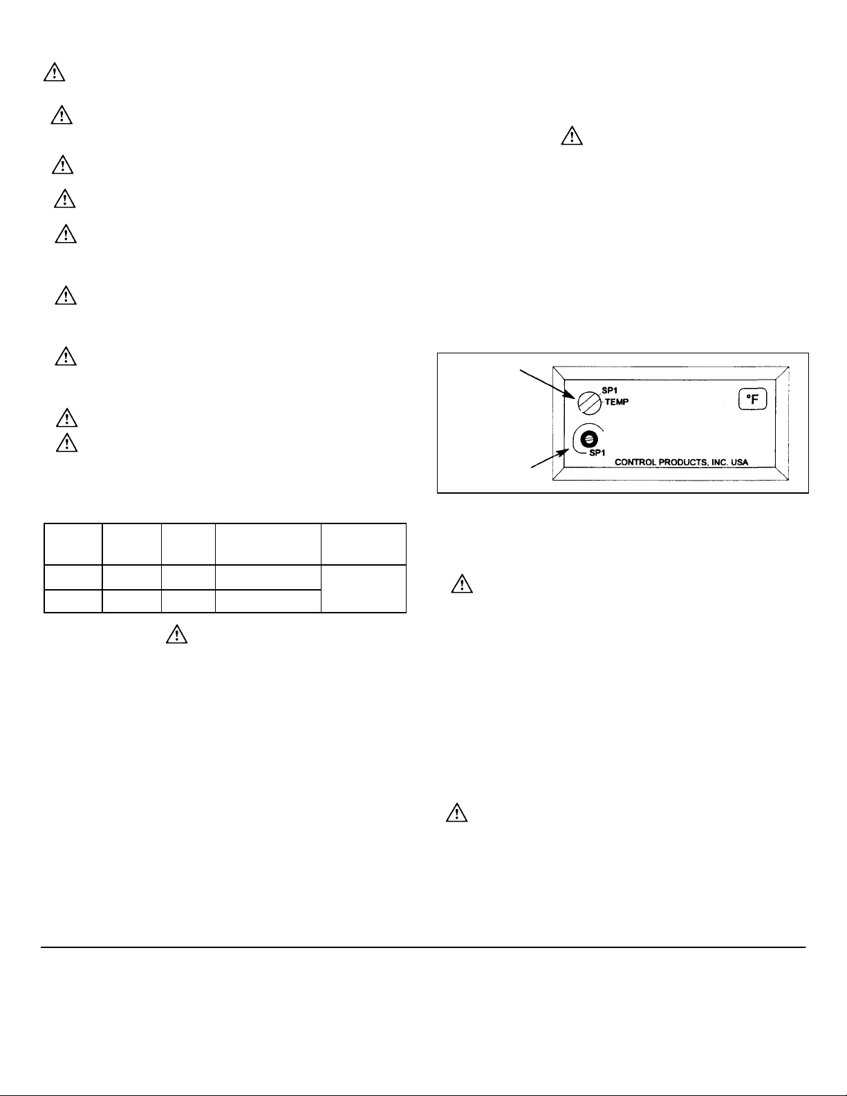
Setpoint Screw
Printed June
1
998 Form No. AFSTM
-
0698
by qualified service personnel only.
SAFETY PRECAUTIONS
To avoid any injury, turn the power switch off, unplug the
unit from the power source and allow to cool before performing
any maintenance.
Some exterior surfaces on the unit will get hot. Use caution
when touching these areas to avoid injury.
The unit must be transported in an upright position. If laid
on its side, all glass surfaces must be secured with tape.
For safe and proper operation, the unit must be located a
reasonable distance from combustible walls and materials. If safe
distances are not maintained, discoloration or combustion could
occur.
Locate the unit at the proper counter height, in an area that
is convenient for use. The location should be level to prevent the
cabinet or its contents from accidentally falling, and strong
enough to support the weight of the unit and food displayed.
5. Allow 15-20 min 5. Allow 15-20 minutes for unit to reach operating temperature.
Plug the unit into an electrical outlet of the correct voltage,
size and plug configuration. If the plug and receptacle do not
match, contact a qualified electrician to determine the proper
voltage and size, and install the proper electrical outlet .
Abrasive cleaners could scratch the finish of your unit.
0nly bulbs which meet or exceed N.S.F. standards, specifi-
cally designed for food holding areas must be used. Breakage of
bulbs not specially coated could result in personal injury and/or
food contamination.
ELECTRICAL SPECIFICATIONS
Plug
Voltage Wattage Amps
120/208 1835 11.7 NEMAL14-20P
120/240 1835 11.7 NEMAI.14-20P
Configuration
Shipping
Weight
188lbs.
(85 kg)
CAUTION
Before Installing plug into electrical receptacl e, measure
voltage at the receptacle from "neutral" to each "hot leg".
Voltage at these connections must not exceed 125 Volts.
DIMENSIONS
Overall Dimensions
32-7/8”L x 27”D x 30”H (83 x 69 x 76 cm)
Rack Dimensions
27”W x 19-3/4”D x 21-1/4”H (69 x 50 x 54 cm)
INSTALLATION
1. Remove unit from box.
2. Remove tape, packing materials and protective film from all surfaces
of unit.
3. Install door handles to top of doors using the screws provided.
4. Install the display signs and acrylic panels into the brackets at the top
of the cabinet sides.
OPERATION
1. Plug unit into an electrical outlet of the correct voltage, size
and plug configuration. See Electrical Specifications for
details.
CAUTION
Before Installing plug Into electrical receptacle, measure
voltage at the receptacle from "neutral" to each "hot leg".
Voltage at these connections must not exceed 125 Volts.
2. Turn the Power Switch on the control panel to the ON posi-
tion.
3. To set temperature, turn the red Mode Switch counter clock-
wise to the SP-1 posi tion indicated on the controller.
4. Adjust the Set point Screw to the desired temperature and
turn the red Mode Switch to the TEMP position. The surface
temperature range is room temperature to 220° F. (104°C).
Mode Switch
Control Panel
MAINTENANCE
Your Holding & Display Cabinet is designed for maximum dura-
bility and performance, with minimum maintenance.
To avoid any injury, turn the power switch off, unplug the
unit from the power source and allow to cool before performing
any maintenance.
CLEANING
To preserve the bright finish of the cabinet, it is recommended
that the exterior and interior surfaces be wiped daily with a damp
cloth. Stubborn stains may be removed with a good stainless
steel cleaner or a non-abrasive cleaner. Hard to reach areas
should be cleaned with a small brush and mild soap.
Abrasive cleaners could scratch the finish of the cabinet.
Clean the glass sides using a common glass cleaner.
LIGHT BULB REPLACEMENT
The display lights are shatter-resistant incandescent light
bulbs which illuminate the warming area. These bulbs have a
special coating to guard against injury and food contamination in
the event of breakage.
1. To replace a bulb, disconnect the power supply from the unit
and wait until the unit has cooled.
2. Bulbs have a threaded base. Unscrew the light bulb from the
unit and replace it with a new specially coated incandescent
bulb.
Page 3

Model AFST
-2X
NOTE: Hatco shatter-resistant tight bulbs meet N.S.F. standards for
1
food holding and display areas. For 120 Volt applications, use Hatco
part #02.30.043.00.
Only bulbs which meet or exceed N.S.F. standards, specifically
designed for food holding areas, must be used. Breakage of bulbs not
specially coated could result in personal injury and/or food
contamination.
ITEM DESCRIPTION PART NO. QTY. ITEM DESCRIPTION PART NO. QTY.
1. Thermostat, Probe 02.01.056.00
2. Heating Element, 800 Watt R02.08.010A.0 1 19. Screw, Hinge 04.17.496.00 4
3. Heating Element, 600 Watt R02.08.091.00 1 20. Hinge Bracket, Left Hand 04.17.501.00 2
4. Blower Motor 02.12.001.00 1
5. Connector, Blower Motor 02.12.001A.00 1 21. Hinge Bracket, Right Hand 04.17.502.00 2
6. Terminal Block 02.15.012.00 1 22. Door Hinge 04.17.503.00 8
7. Transformer, 120-24V 02.17.040.00 1 23. Cover, Hinge Spring 04.17.504.00 4
8. Power Cord with Plug 02.18.132.00 1 24. Top Cover, Painted 04.17.507.00 1
9. On/Off Switch 02.19.015.00 1 25. Screw, Hinge 05.04.146.00 4
10. Cord Grip or Heyco Strain Relief 02.20.233.00 1 26. Door Magnet 05.30.005.00 4
11. Light Bulb, 60 Watt 02.30.043.00 6 27. Electronic Temperature
12. Single Light Socket 02.30.060.00 2
13. Dual Light Socket 02.30.061.00 2 28. Relay, 30A, 24DC R02.01.050.00 1
14. Self-Closing Spring, Left Hand 04.17.492.00 2 29. Thermostat, Limit Disk, 173° F R02.16.029.00 1
(not shown)
15. Self-Closing Spring, Right Hand 04.17.493.00 2 31. Door, Right Hand (Complete) AS.257.00 2
16. Shelf Rack 04.17.494.00 1 32. Door, Left Hand (Complete) AS.256.00 2
17. Removable Shelf 04.17.494A.00 3 33. Door Handle Only R05.30.012.00 4
I8. Stop, Hinge Spring 04.17.495.00 4
(not shown)
Controller with Probe R02.01.049.00 1
30. Thermostat, Limit Disk, 255° F R02.16.031.00 1
Printed June 1998
Form No. AFSTM-0698
Page 4

WIRING DIAGRAM
Model AFST
-2X
Printed in U.S.A.
June
1998
Form No.
AFSTM
-
0698
P.O. Box 340500, Milwaukee, WI 53234-0500 U.S.A.
HATCO CORPORATION
(800)558-0607 (414)671-6350
Parts & Service Fax (800) 690-2966 Int'l. Fax (414) 671-3976
Web Site: www.hatcocorp.com
 Loading...