

Page 1
USER MANUAL
v3
1
Page 2

INTRODUCTION
2
Page 3
The Hasselblad H series of cameras consists of building new
developments on the shoulders of the previous generation.
In this way all the previous work-experience based and
branch-demanding features are automatically included. So,
just when you think things can't get much better, they do.
And the H5D is that model - all the good things from before
and then some!
The H5D series heralds a step up that is noticeably greater
than before. There are changes and many are 'from the
ground up'. The H spirit thrives but has now matured to
reinforce further its position in the rapidly changing world of
digital imaging. Future proofing is key to a secure placing for
working photographers. The H5D provides a reliable
connection to the fleeting environment of digital imaging
technology so when the wind changes direction, the H5D
remains as the safeguarding companion to provide support.
Medium format photography is about
professionalism. Camera systems have to be
professional, handling has to be professional and
captures have to be professional in quality.
Hasselblad knows it and delivers it; professionals
know that too.
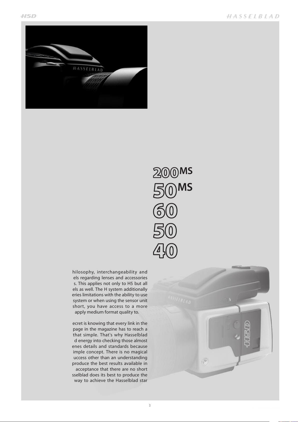
There are five models to choose from to suit the varied
demands from the professional world. They start with the
entry level 40 MPixel model that right from the outset
confidently takes on most rivals from all brands and beats
them with star quality results. The models then just get
better and better. At the other end of the scale is the 200
MPixel MultiShot model that raises the bar so much for
product work that it is in a league of its own.
True to Hasselblad philosophy, interchangeability and
versatility span all models regarding lenses and accessories
with minimal restrictions. This applies not only to H5 but all
H1, H2, H3 and H4 models as well. The H system additionally
breaks rank regarding series limitations with the ability to use
other lenses from the V system or when using the sensor unit
on view cameras. In short, you have access to a more
comprehensive world to apply medium format quality to.
Hasselblad's best kept secret is knowing that every link in the
chain that leads to the page in the magazine has to reach a
certain standard; it is that simple. That's why Hasselblad
spends so much time and energy into checking those almost
endless behind-the-scenes details and standards because
they understand this simple concept. There is no magical
formula to Hasselblad success other than an understanding
of what is required to produce the best results available in
the world today and an acceptance that there are no short
cuts in this process. Hasselblad does its best to produce the
best; there is no other way to achieve the Hasselblad star
quality.
3
Page 4

The H5 models have a good deal in common. Stainless
steel and aluminium were the materials chosen to endure the
treatment handed out in professional use – and that can be
pretty tough.
The sturdy but ergonomic integral grip incorporates not only
the battery but one of the user interfaces too. It is here, by
way of the surrounding buttons, that you enter the ‘control
room’. Customization is a very prominent concept that you
experience in the Hasselblad world that ensures it is the
photographer that controls the camera, not vice versa.
Accessed through the grip alone, there are 34 separate
custom options.
The standard prism viewfinder provides not only the most
popular way of viewing but the sophisticated light metering
system too. Don’t forget the waist-level accessory model if
you prefer it.
And when all the hustle and bustle and rushing around is
over for the latest glossy cover and you settle back into a
more reflective mode for some seriously detailed product
shot you consider your Hasselblad. You remove the sensor
unit and slip it onto your large format your studio set up
where movements, controlled depth of field and close-up
clarity rule. Now that is versatility.
All models feature:
• Stainless steel/aluminium camera body
• Access to 12 H system lenses
• Access to most V system lenses by CF Adapter accessory
• Access to all H accessories
• 40 Custom options
• Hasselblad Natural Color Solution
• Tru e Focus
• Digital Lens Correction
• Access to view camera use
• Hasselblad Phocus and Adobe Lightroom
• International Warranty & Service package
50MS & 200MS models also feature:
• Multi-Shot facility
On the softer side of things all models share features that
professionals rely on for fast tracking their progress.
Camera Configuration in conjunction with Phocus offers a
powerful tool to provide intuitive, easy and rapid control of
all the parameters you don't want to forget in the heat of the
moment. Custom build camera profiles with total control in
advance to ensure the optimum in shooting security.
HNCS – Hasselblad Natural Color Solution – saves time and
secures the job because skin tones or specific product tones
are going to be rendered automatically, accurately and
immediately without any fuss. That can be worth a lot.
True Focus is the pet feature for many fashion
photographers who work fast and by instinct. They don’t
have the time to double check focus for every single split
second shot and neither do they have the time to get it
wrong. True Focus delivers the sharpness in an intuitive
manner, at speed.
IFC – Immediate Focus Confirm – for True Focus users who
have a second to spare and a desire to know the focus is
exactly on target regarding specific areas. Intuitively and
directly displays inspection of captures at 100% pinpointing
the original focus selection.
H System lenses and accessories include:
• 24, 28, 35, 50, 80,100,150, 210, 300
• 120 Macro
• 50-110 & 35-90 zooms
• 1.7x converter & Macro converter
• CF adapter (to be able to use V system lenses)
• HTS 1.5 tilt/shift adapter
• GIL (Global Image Locator)
• Battery Adapter for technical camera use
Medium format advantage means:
• Shallow depth of field
• Huge sensors for unbeatable image resolution
• Super smooth color and tone rendition
• Enlargements in breathtaking quality
JPEG & RAW files can be produced simultaneously if you
choose. The JPEG files are not only 1/4 resolution they are
also HNC profiled so you can print straight from a folder for
amazing quality. RAWs are retained of course for your final
masterpieces.
Digital Lens Correction, applied at the file editing stage,
takes a discerning look at any colour aberration, distortion
and light fall off however minor (which is inherent in any
lens, anywhere) and resolves the situation automatically.
4
Page 5

INDEX
Introduction 2
System requirements 6
Warnings & restrictions 6
General overview –
controls and displays 7
Parts, components, buttons 7
Grip buttons & controls 8
Camera body buttons & controls 9
Sensor unit 10
Viewfinder 11
Lenses 11
Display overview 12
Sensor unit display 13
Grip display 14
Viewfinder display 15
Customizable buttons 16
Camera Configuration 17
Shortcuts 18
General 18
Carrying strap 20
Rechargeable battery 20
Battery charger 20
Charging the battery 21
Battery grip − precautions 21
Battery life 22
Battery status 22
Power modes 23
Viewfinder screen 23
Attaching /removing the viewfinder 24
Eyepiece adjustment 24
Rubber eyecup 24
Accessory connection 24
PC-connector 24
Protective baseplate 25
CF cards 25
Inserting/removing CF cards 25
Formatting CF cards 26
Removing/attaching sensor unit 27
Sensor unit maintenance 27
Cleaning sensor unit filter 28
Tethered to a computer 28
Capture files 29
Phocus 30
Lenses & focus modes 31
Attaching/removing a lens 32
Lens cap 32
Lens shades 32
Shutter and aperture control 32
Filters 32
Focusing distance calculation 32
Depth-of-field preview 33
Infrared focus settings 33
Focus assist 33
Manual focus 35
Autofocus 35
Single shot 36
Continuous 36
True Focus 36
True Focus, Absolute position lock 37
True Focus and camera handling 38
Focus checking 38
True Focus, four methods 39
Exposure Control 41
ISO & white balance on grip 42
Light metering modes 42
Exposure setting modes 43
Manual exposure mode 43
Automatic exposure mode 44
Overexposure indicator 44
AE-L button 45
Exp compensation/Quick Adjust 46
Fixed Exposure compensation 46
Navigating the Menus 46
Sensor unit menu 48
Navigating menu and settings on SU 49
Navigating menu and settings on grip 50
Previews and browsing 51
Preview modes 52
Browsing 53
Zooming 53
Sensor unit settings 54
Sensor unit menu layout 55
ISO & WB setting on sensor unit 56
Image Format 57
Storage 58
Delete 58
Format 58
Settings 59
Sound 59
Date & Time 60
Display 60
Custom Options 61
P1 & P2 Buttons 61
Display Off 61
Sleep 61
Power Off 61
Image Orientation 62
Show Preview 62
Service 62
About 63
Spirit level 64
Grip Menu Settings 65
Overview of grip menu 66
Self Timer 67
Bracketing 69
Interval 71
Settings 72
Custom Options 73
Image Info 77
Image info text setting 78
Date & Time 78
System status 79
Drive 80
Profiles 81
Profiles 82
Flash /strobe 84
General 85
Integral flash 86
Flash measure 87
Accessories 88
Multi Shot 93
Appendix 94
Technical Specifications 95
Default settings 97
True Exposure 98
P & Pv modes 99
Light metering sensitivity 99
Recommended CF cards 99
Problems, Equipment care and service 100
Index 101
5
Page 6

COMPUTER SYSTEM REQUIREMENTS
Image-storage and editing requires a certain minimum standard regarding computer capabilities. Large images require a reasonably high-performance computer with plenty of memory, advanced graphics capabilities and a recent operating system. In
most cases, the computer should include a FireWire connector, which will enable you to load images directly from the camera.
To load captures stored on the removable compact-flash card, you could instead use a USB CF-card reader, but FireWire is recommended for optimum speed and flexibility.
WARNINGS, RESTRICTIONS AND RECOMMENDATIONS
• If you want to power the H5D from a PC laptop (as opposed to a Macintosh laptop), you must ensure that the FireWire port
on the computer is capable of supplying power. Please note the following:
Most recent Macintosh computers are compatible, both desktops and laptops.
Most recent desktop PC computers are compatible.
Most laptop PC computers are not compatible (but can be modified in many cases).
• Keep the H5D and computer equipment away from moisture wherever possible. If your camera becomes wet, disconnect
from power and allow it to dry before attempting to operate again.
• Always take great care when you remove the sensor unit for cleaning as the exposed CCD sensor protective filter is
vulnerable to damage.
• Keep all cables connected to or from your camera and computer out of the way where they will not be tripped over.
• Your new Hasselblad camera may have been supplied in kit form or as separate items. There are a number of possible
combinations depending on factors such as offers, bundles etc. Please ensure that all the items noted on the
accompanying packing information have been supplied and are correct.
• Contact your Hasselblad dealer or distributor immediately if anything is missing or seems faulty in any way, quoting the
serial numbers and purchase details where appropriate.
• Please keep purchase details and the warranty in a safe place.
• Become familiar with the various parts and components. Leave protective covers on as much as possible and avoid
touching glass surfaces and inserting fingers into the camera body. Hasselblad cameras have a robust construction and are
capable of withstanding fairly rough treatment but nevertheless are precision instruments and will serve you longer if
treated with respect from the beginning.
FIRMWARE UPDATES
If you have registered your camera you should automatically receive e-mail informing you of the latest developments. Otherwise you are advised to make regular checks regarding firmware updates to the camera body, the sensor unit and the viewfinder.
The aim is to ensure you have the latest firmware updates for camera body, sensor unit and viewfinder, which naturally ensures the optimum in performance. When updating you should also study the accompanying ‘Release Notes’ or ‘Read Me’ files
where you will find details about improvements, developments and changes.
USER MANUAL
This user manual is primarily designed for on-screen PDF reading to exploit search tools etc. However, there is a sufficiently
wide left margin to allow one-sided print outs to fit an ISO standard ring binder if required.
Please note that the format is A4 to conform with the most common standard. Therefore if printing out to US Letter format or
similar please ensure you select “Fit to Printable Area” in the page scaling dialogue.
Register your camera for regular news about the latest developments, updates, news, tips, and much else!
– www.hasselblad.com –
6
Page 7
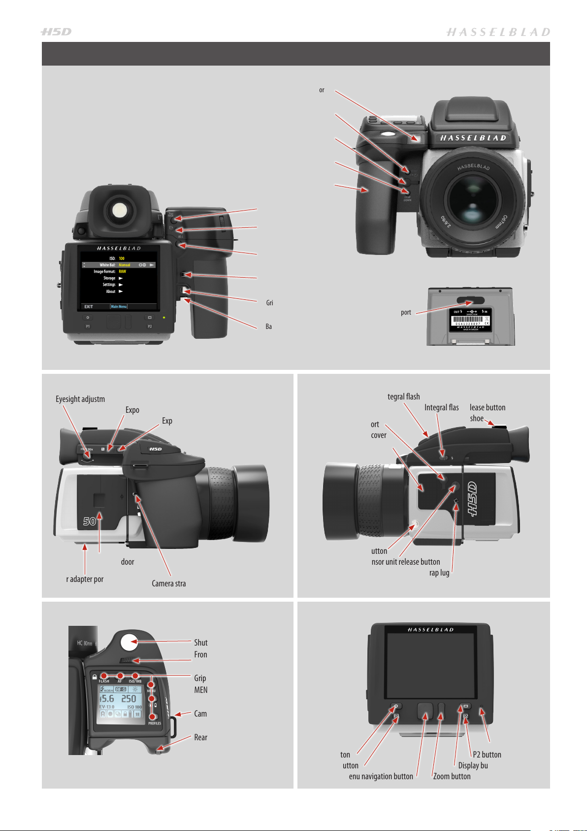
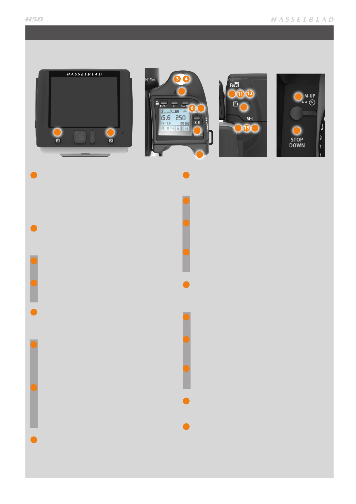
PARTS, COMPONENTS, BUTTONS AND CONTROLS – OVERVIEW
All of the items named on this page are described
in greater detail elsewhere in this manual.
Focus Assist illuminator
Mirror Up button
Remote release port
Stop Down button
Battery grip
True Focus button
Card format button
AE-L button button
Camera strap lug
Grip lever release button
Battery Adapter port
Battery grip locking lever
Eyesight adjustment wheel
Exposure compensation button
Exposure DISPLAY button
CF card door
Power adapter port
Camera strap lug
Shutter release button
Front scroll wheel
Grip buttons: Flash, AF, ISO/WB,
MENU, Battery check, Profile
Integral flash
Integral flash release button
PC connector port
Hot shoe
Accessory port cover
Lens release button
Sensor unit release button
Camera strap lug
Camera strap lug
Rear scroll wheel
Menu button
P1 button
Menu navigation button
7
Ready light
P2 button
Display button
Zoom button
Page 8
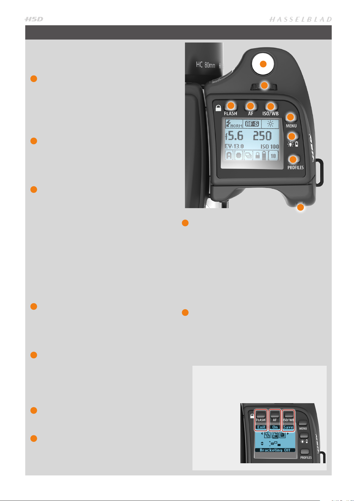
GRIP BUTTONS AND CONTROLS
Note that some of the buttons are modal and so
have multiple functions according to the setting being made.
1
Shutter release button
This button has half-press and full-press positions.
By pressing half-way (or softly) the camera, auto focus
function and exposure meter can be activated. By
pressing all the way down (or more firmly) the shutter
will be released (or the chosen exposure procedure
for example, the self timer is activated with this button).
2
Front scroll wheel
The front and rear scroll wheels are used to make
changes in exposure settings, provide access to the
grip menu for settings, navigate the sensor unit’s
menu as well as acting as browse controls. The effect
of the wheels’ direction is customizable.
3
FLASH / (Control Lock) button) / (EXIT)
This is a triple function button. If you press the button
for one second, the beeper will sound (if set) and a key
symbol will appear on the grip display signifying that
the controls (except the shutter release) have been
locked and therefore cannot be altered unintentionally in use. Press the button for one second again to
unlock (this function can be altered to lock all controls
or scroll wheels only in Custom Options #18 on grip).
Quickly clicking the button will access the flash settings information on the display from the main screen.
See under Flash /Strobe - controls and displays for full
details.
This button also acts as the EXIT button for many
other settings including an EXIT button when navigating the sensor unit menu.
4
AF button / (ON) / (SEL.)
This is a triple function button. Press this button to
directly access the autofocus/manual focus choice
screen from the main screen. See under Lenses for full
details. It also acts as the ON and SEL. (= select) buttons for many other settings.
5
ISO/WB button / (SAVE) / (ENTER)
This is a triple function button. It provides direct access to the ISO and White Balance settings (see under
Light Metering & Exposure Control for full details).
It also acts as the SAVE and ENTER buttons for many
other settings as well as an OK button when navigating the sensor unit menu.
6
MENU button
Accesses the first level of the menu for settings
changes.
7
Illumination/Battery status button
Press to illuminate the display. Remains active until
camera enters Display Off mode. Hold down to access
battery status/general information screen.
1
2
3
8
ON / OFF (Profiles) button
Press the button for 1 second to activate the camera.
The H5D start-up logo will appear and then the main
screen. After a few seconds (customizable) the camera
will enter Display Off mode.
A long press of the button will turn the camera off
completely (even from Display Off mode) signified by
an audible signal (if set).
A quick ‘click’ on the button will access the Profiles
feature (see later section for deatils).
Note the difference in results between a long press
and a quick click of this button.
9
Rear scroll wheel
The front and rear scroll wheels are used to make
changes in exposure settings, provide access to the
grip menu for settings, navigate the sensor unit’s
menu as well as acting as browse controls. The effect
of the wheels’ direction is customizable.
4
5
6
7
8
9
EXAMPLE
In this example of making a Bracketing setting, the
top three buttons – Flash, AF and ISO/WB – will temporarily function according to the description on the
screen – Exit, On
and Save.
The buttons return to the standard function
when you exit
from the setting.
8
Page 9
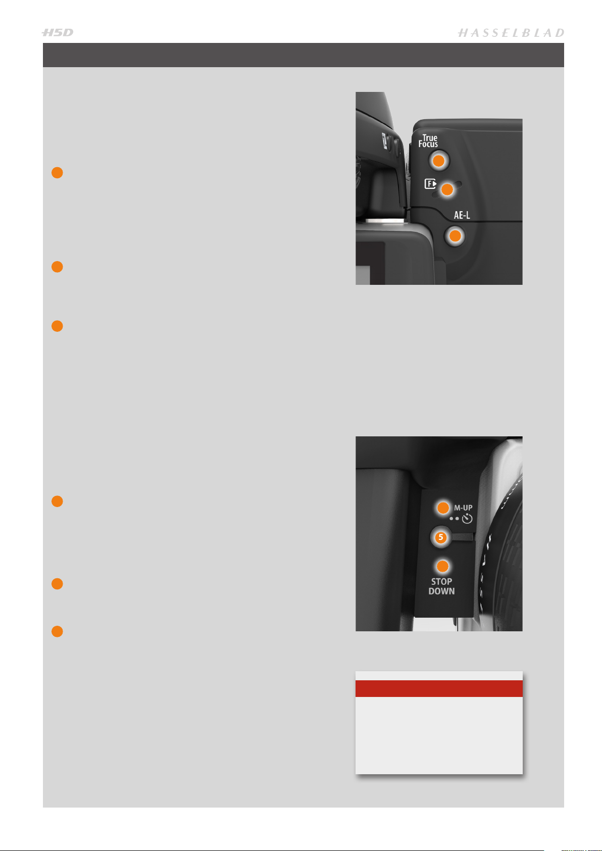
CAMERA BODY BUTTONS AND CONTROLS
Note that some of the buttons can be re-assigned to
another function.
There are three control buttons on the rear of the
grip.
1
True Focus button
At default setting, activates True Focus (see separate
section for description) but also acts as a Zoom-in
button when browsing or Selector button when
making a setting change on the sensor unit, according
to mode.
Can be reassigned in Custom Options to another function.
2
CF Card format button
Re-formats a CF card. Purposefully recessed to prevent unintentional use. Dialogue appears for confirmation.
3
AE-L button
At default setting, activates AE-L that can lock a light
reading made in both automatic and manual exposure modes. Also acts as a Zoom-out button when
browsing or Selector button when making a setting
change on the sensor unit, according to mode.
Can be reassigned in Custom Options to another function.
See under Light Metering & Exposure Control /
AE-L button for full details.
1
2
3
There are three control buttons on the front of the
grip.
4
M.UP button
Press to raise the mirror and press again to lower it
(toggle function). A quick double press of the button
(two within a half second) will immediately access the
Self timer function.
Can be reassigned in Custom Options to another function.
5
Remote release cord port
For attaching a remote release cord (electrical). The
jack plug socket is protected by a captive rubber plug.
6
STOP DOWN button
Press to make a visual check of the depth-of-field on
the viewfinder screen at the chosen aperture. The aperture will close according to the setting and remain
closed as long as the pressure is maintained. You can
alter the aperture at the same time to see the changes
taking place.
Can be reassigned in Custom Options to another function.
4
5
6
Note
Customizable buttons are parti cularly
useful and can save you a great deal of
time and effort. You are advised to investigate their potential fully!
See separate section for full details.
9
Page 10
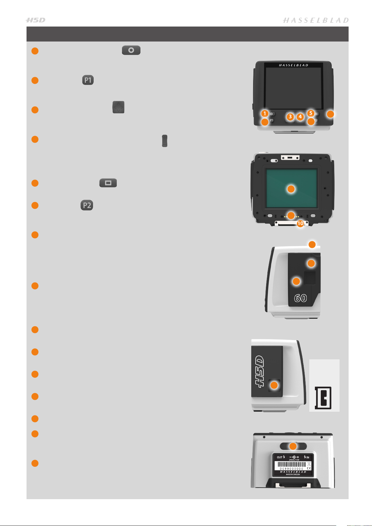
SENSOR UNIT
1
MENU / (EXIT) button
Opens and closes the menu system. Also used for various other tasks (EXIT
button, for example) as you issue commands navigating the menu system.
2
P1 button
Assignable button to access a specific function. Setting is made via Custom Options on sensor unit or in the Camera Configuration tool in Phocus.
3
Navigation button
A four-way rocker button enabling you to browse images as well as navigate the menu system.
4
Zoom- in/-out (Selection) button
Zoom-in /out rocker button for the preview image. You can zoom in to
view close-ups of previews for focus checking. You can zoom out to view
several at once and finally to view and select folders and media. Also acts
as a selection button for value setting on the sensor unit menu.
5
Display button
Steps through the various view modes for the preview image.
6
P2 button
Assignable button to access a specific function. Setting is made via Custom Options on sensor unit or in the Camera Configuration tool in Phocus.
10
5
6
7
1
2
3 4
8
9
7
Ready-light
Indicates sensor unit condition. GREEN signifies a new capture is possible
(steady or blinking). ORANGE signifies the unit is busy (writing to a CF card
or sending data, for example) and so a new capture is not possible, although
settings can be changed. RED signifies a problem (an explanatory message
will be displayed).
8
CCD and IR filter
The sensor is positioned behind a permanently mounted IR filter. Always
be very careful not to touch or scratch the surface of the filter when it is
exposed. Replace the protective cover whenever the sensor unit is not
mounted on a camera.
9
Databus connectors
For digital communication with camera body.
10
Retaining bar
Main support for sensor unit.
11
Safety catch
Prevents inadvertent removal of sensor unit.
12
‘Sensor plane’ index
For physical focus measurement in critical close-up work.
14
13
11
12
Previous H2 /
H3/H4D users
please note th e
orientatio n of the
plug on the H5D!
13
CF-card cover
14
FireWire port
For computer connection (please carefully note the orientation of the
FireWire plug when inserting into the sensor unit).
15
Flash sync and power connector ports
Flash sync ports and port for external power supply / battery adapter for
when the sensor unit is used with a view/large format camera. Protected
behind a rubber cover.
10
15
Page 11
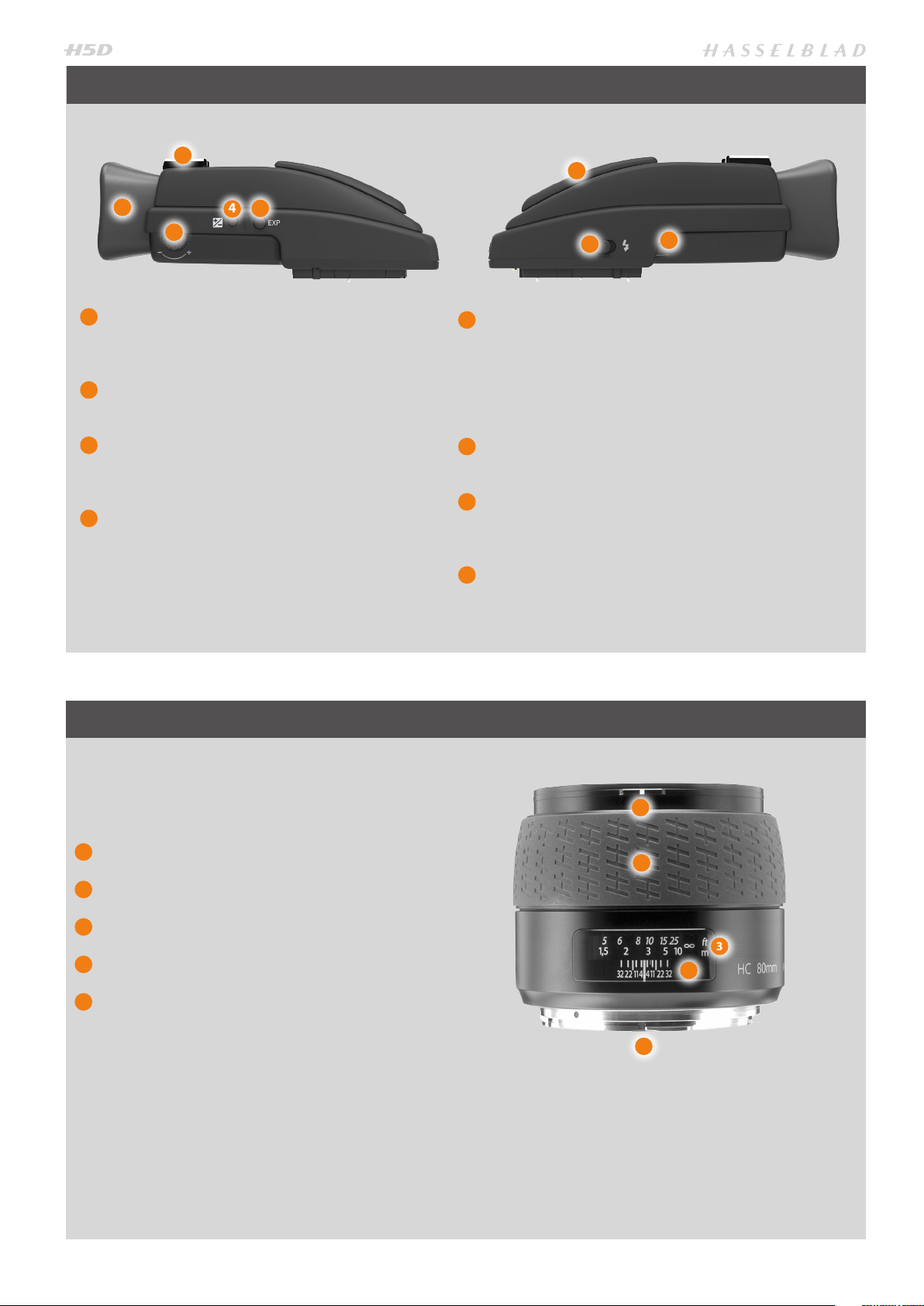
VIEWFINDER
1
2
3
1
Hot shoe
Connection for automatic flash unit (with SCA 3902
adapter) or for wireless flash connection.
2
Rubber eye cup
Can be exchanged for another model.
3
Eyesight adjustment wheel
The personal eyesight adjustment facility has a diopter range of -5 to +3.5, to suit most users.
4
Exposure compensation button
Press this button to access the EV compensation
screen. Settings are made with either the front or rear
scroll wheels. An EV correction symbol appears on
the grip and viewfinder display as confirmation.
5
4
6
7
5
Exposure method / DISPLAY button
The EXP (Exposure) button accesses the exposure and
metering mode options screen. Settings are made
with the front and rear scroll wheels and the appropriate symbols appear on the grip and viewfinder
displays accordingly.
6
Integral flash unit
Guide number 12.
7
Integral flash unit release button
Slide the button towards the rear of the camera to
raise the flash. Activation is automatic.
8
Viewfinder release button
8
LENSES
1
Lens shade index
2
Manual focus ring
3
Focusing distance scales
4
Depth-of-field scales
5
Lens index
See more user details in the ‘Lenses’ section in this
manual.
Also, you can download technical data sheets from the
Hasselblad website, or you can download a combined
version - well as a lens booklet that contains a round up of
the available lenses as well as some general information.
1
2
3
4
5
11
Page 12

DISPLAY INFORMATION − OVERVIEW
VIEWFINDER INFORMATION
• Metering method
• Aperture setting
• Shutter speed
• Exposure method
• Capture counter
• Exposure compensation
• Focus assist
• Warning triangle
• Flash warning
• Spirit level
GRIP LCD INFORMATION
• Metering method
• Aperture setting
• Shutter speed
• Exposure method
• Capture counter
• ISO
• White Balance
• Flash indication
• Focus
• Drive
• EV
• Battery status
.....optional.....
• Histogram
PHOCUS / PHOCUS MOBILE INFORMATION
• Metering method
• Aperture setting
• Shutter speed
• Exposure method
• ISO
• White Balance
• Flash indication
• Focus
• Drive
• EV
• ISO
• White Balance
• IAA rating
• Storage medium
Optional instantly accessible full-screen
display of grip information to show:
12
REAR LCD INFORMATION
.....optional.....
• Exposure compensation
• Histogram
• Date
• Time
• Focal length of lens
• Spirit level
Metering method
Aperture setting
Shutter speed
Flash indication
Focus
Drive
EV
Battery status
Exposu re method
Capture counter
ISO
White balance
Page 13
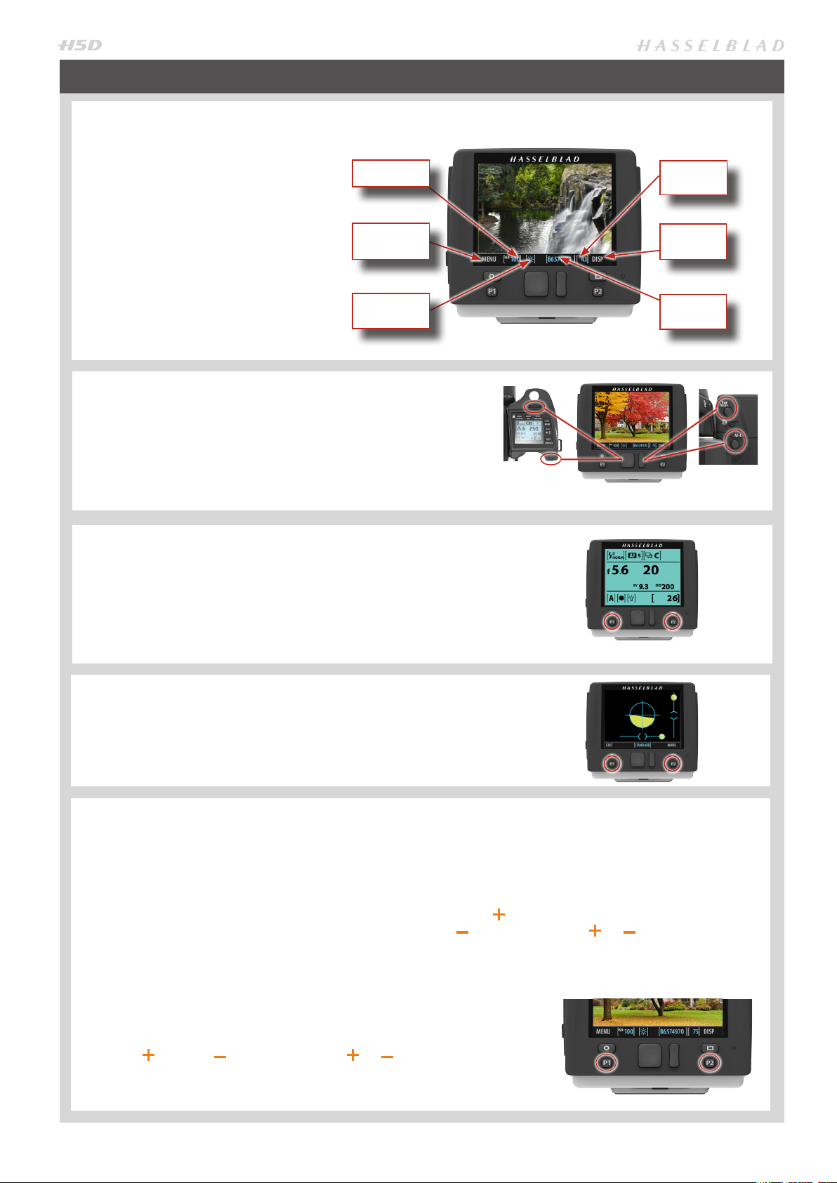
SENSOR UNIT DISPLAY AND CONTROLS − OVERVIEW
When shooting, the sensor unit can
display the information most often required for a quick settings check. The
unit’s buttons, grip scroll wheels and
camera buttons are used to navigate
the main menu and change settings.
ISO setting
Capture
counter
The display can show all saved captures on a CF card for browsing and
enlarge them for detailed inspection.
When shooting, you can control the
amount of information visible together with the current preview by choosing various modes
BUTTONS AND SCROLL WHEELS
In Browse mode, the scroll wheels and True Focus and AE-L
buttons on the grip duplicate the actions of the Navigation
and Zoom /selection buttons on the sensor unit.
Activate Browse mode by clicking on the Navigation button,
the Zoom button or one of the P buttons (when assigned to
Browse activation).
GRIP INFORMATION
Certain grip information (such as: aperture setting, shutter
speed, flash indication, focus setting, drive, EV, battery status,
exposure method, capture counter, ISO and white balance) can
simultaneously be displayed on the sensor unit. This feature is
activated by pressing one of the P buttons (when assigned to
Info Screen activation).
Button
function
White
balance
Button
function
File name
SPIRIT LEVEL
Spirit levels can be displayed on the sensor unit (a horizontal
spirit level is also visible in the viewfinder simultaneously).
This feature is activated by pressing one of the P buttons
(when assigned to Spirit Level activation).
P1 & P2 BUTTONS
The P1 and P2 buttons on the sensor unit are customizable
buttons that rapidly access a variety of functions, which are:
Delete image • Format card • Info screen • Spirit level
• Focus conrm • Browse mode • Mark Overexposure
The buttons are easy to reassign either on the sensor unit
itself or by way of the Camera Configuration tool in Phocus.
P1 & P2 BUTTON ASSIGNATION ON SENSOR UNIT
(TWO METHODS)
1. Press MENU.
2. Press P1 button or P2 according to choice.
3. Step through the available options by pressing the True
Focus ( ) or AE-L ( ) buttons or ZOOM ( or )
button.
4. Save the selection option by pressing EXIT (Menu button).
or
1. Press MENU > SETTINGS > CUSTOM OPTIONS.
2. Select P1 button or P2 according to choice.
3. Step through the available options by pressing the True
Focus ( ) or AE-L
( ) buttons or ZOOM ( or ) button.
4. Save the selection option by pressing EXIT (Menu button).
13
Page 14
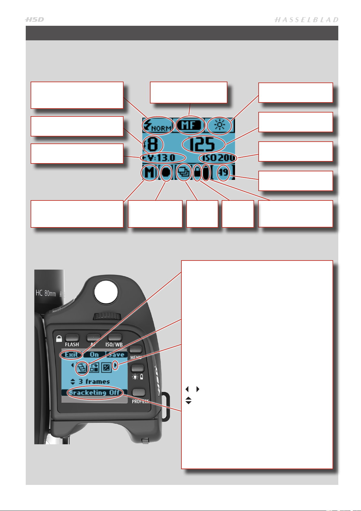
GRIP DISPLAY − OVERVIEW
TYPICAL GRIP DISPLAY
Flash condition indication
(No exposure compensation,
normal flash synchronisation)
Aperture setting
(f/8)
Exposure Value display
(E V 13.0)
Exposure mode indication
(Manual setting)
Focus setting
(Manual setting)
Metering method
indication
(Centre weighted)
Drive
condition
Key lock
White balance
(Daylight)
Shutter speed setting
(1/125s)
ISO setting
(200 ISO)
Capture counter
Battery symbols
Command indication
The upper row on the screens describes commands (that
change according to the setting). The button immediately
above each command effects the change. So in this case, for
example, you would press the FLASH button to Exit from the
screen. See note below.
Settings symbols
Symbolize the options available when settings are changed.
The active symbol is depicted by a drop shadow.
Scroll wheel description and direction
Arrowheads symbolize which scroll wheel should be used to
change the setting they are beside. In this case, the Bracketing option is chosen by the front scroll wheel and the number of captures in that option is chosen by the rear scroll
wheel.
. . .
= front scroll wheel
= rear scroll wheel
Setting information
The lower row on the screen displays information about the
current state of the setting. In other words, the upper row
displays what you can do, and the lower row displays the
current state of settings or what you have done.
Typical camera grip display when changing
settings.
14
Page 15
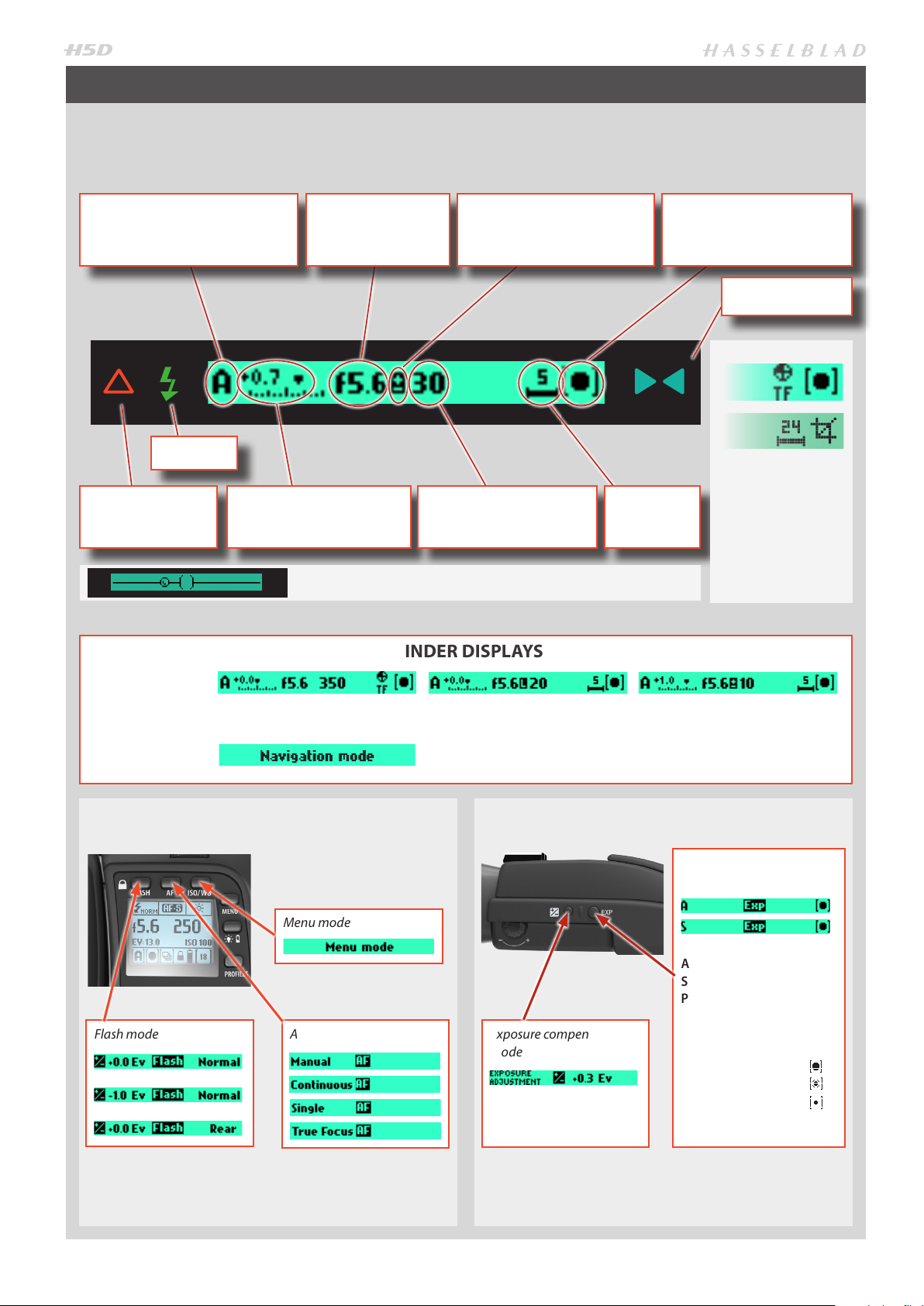
VIEWFINDER DISPLAY − OVERVIEW
Typical viewfinder display. Note the LEDs will only be visible when activated (by the camera or a setting).
Exposure method indication
(‘aperture priority’ mode)
Flash LED
Warning triangle
LED
Exposure compensation
setting (+0.7 EV)
Aperture setting
(f/5.6)
Exposure compensation
setting reminder symbol
Shutter speed setting
(1/30 second)
When activated, the integral spirit level replaces normal display.
SOME EXAMPLES OF VARIOUS VIEWFINDER DISPLAYS
Capture
counter
Metering method
setting
(Centre weighted)
Focus Assist LED
True Focus (all models) and HCD crop (60
Mpix only) icons
appear on right
hand side of display
when functions are
activated.
Standard settings
Normal screen with True Focus
activated
VIEWFINDER DISPLAY ACCORDING TO
Normal screen with AE lock
activated
Display when scroll wheels and navigation button is used or when Browse
mode is activated.
EXPOSURE INFO ON VIEWFINDER DISPLAY
SETTING
Menu mode
Flash mode AF mode Exposure compensation
mode
Normal screen with exposure
compensation set
Exposure and metering
mode examples
A =
Aperture priority
S =
Shutter priority
P =
Program
Pv =
Program (variable)
M =
Manual
Centre Weighted =
CentreSpot =
Spot =
15
Page 16
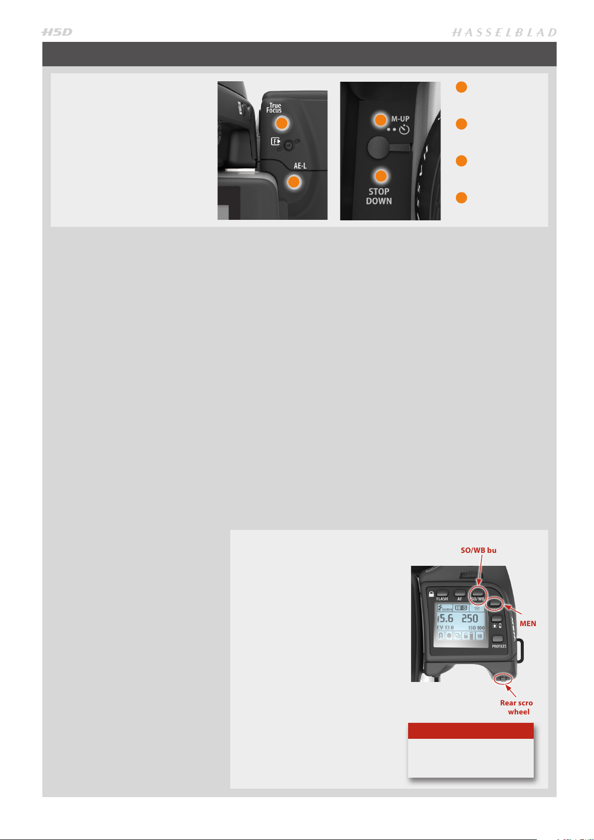
CUSTOMIZABLE BUTTONS FUNCTION OPTIONS
These four grip buttons by default are assigned according to
name but can be reassigned (in
Custom Options #4, #5, #6 and
#7 or by using the Camera Configuration tool) to various other
functions listed here.
(In addition there are two customizable buttons
on the sensor unit: P1 and P2. These are set on the
sensor unit or in the Camera Configuration tool in
Phocus).
· True Focus
Temporarily activates True Focus
function.
· AE-lock
Temporarily locks a light reading
in auto or manual modes. Also
used in Zone metering.
· Mirror up
Locks mirror up for vibration
reduced captures. Also lowers
mirror.
· Stop down
Activates stop down function for
depth-of-field checking.
· AF
Temporarily activates Autofocus
function.
· Self timer
Sets self timer mode. Provides
a timed remote shutter release
function with the option of a
change in sequence of the mirror
movement (to reduce vibration).
· Bracketing
Sets Bracketing mode. This function provides an automatic series
of captures; one at the standard
exposure setting (Manual or
Auto) and the others with predetermined deviations in EV from
the standard exposure.
· B mode
Sets B mode shutter setting.
Shutter stays open as long a
pressure is maintained on shutter release button.
· T mode
Sets T mode shutter setting.
Shutter stays open after first
press of shutter release button
(toggle function to close again).
1
2
· Flash Measure
Activates manual flash measure
function.
· Interval timer
Activates interval function start
screen.
· Cycle Light Meter mode
Selects next light metering mode.
· Expose
Provides alternative to shutter
release button.
· Display Off
Activates Display Off mode immediately.
· Histogram
Provides a histogram on the grip
display for the last capture.
SHORTCUT ACCESS TO
BUTTON SETTING SCREENS
1) Press the MENU button followed by the button you want
to reassign (True Focus, AE-L,
M.UP or Stop Down).
This directly accesses the particular button you chose at the
Custom options level in the
menu.
2) Rotate the REAR scroll wheel to
select the function you want the
button to activate.
3) Press SAVE (or the shutter release
button). The selected button will
now activate the newly assigned
function directly.
1
3
4
2
3
4
· Focus Conf.
Provides a 100% preview on
display for focus checking.
Not available for True Focus and
AE-L buttons.
· Delete
Direct access to delete dialogue.
· Grey balance exp.
Provides selective capture for
grey balance calculations.
· Spirit Level
Activates spirit level on back (but
not in viewfinder).
· Rear Info Screen
Activates grip information on
sensor unit display.
(ISO/WB button)
Tip
See separate section about the
Camera Configuration tool.
True Focus
AE-L
M.UP
STOP DOWN
SAVE
MENU
Rear scroll
wheel
16
Page 17
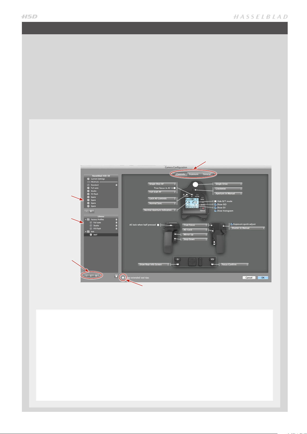
CAMERA CONFIGURATION IN PHOCUS
The Camera Configuration tool in Phocus offers a very thorough and secure way of creating comprehensive profiles for the
H5D. There are three windows – Controls, Exposure and General – that present virtually all parameters to enable total control
at the press of a button. This means that separate and specific custom profiles created in advance can cover a number of
shooting scenarios leaving virtually nothing to chance. In addition these profiles can be easily imported and exported. For
instance, you can create a special profile to suit a specific type of shoot and keep it on a memory stick or laptop. So, when
renting an H5D for example, you only have to upload the saved profile to ensure that all parameters have been reset without you having to go through each detail – simple and secure.
The interface has three tabs at the top, Controls, Exposure and General, that access the windows. Descriptive information appears as you mouse over the various menus and extra tool tips are additionally available as an option. To take an example,
the Controls window is illustrated here. On the left are two lists: Camera and Library. The Camera list includes the various
available configuration profiles already stored in the camera – the profile currently in use as well as the default settings and
those you have created or imported from other sources. Library contains the factory presets stored on disk.
The Camera Conguration interface makes it easy to go through the parameters logically and systematically to prevent
you missing important settings.
Controls, Exposure and General tabs
This list describes
the settings in current use as well as
the profiles already
stored in the connected camera.
This list includes
the new profiles
created in Camera
Configurator as
well as factory
profiles stored on
disk.
Import, Export,
Transfer, Add
Profile etc tools
CREATING A PROFILE
1) Open Camera Configuation located under the
Windows menu.
2) Connect the camera and in the Camera list click on
a profile you want to change or a spare profile and
name it.
3) Cycle through the three windows, Controls,
Exposure and General, making the appropriate
selections that you require. When complete, select
the new profile and drag and drop or right click it
to store in the Library.
Check box to display extended information.
4) Right click the Library version of the profile to
access the Transfer Profile Set to Camera option
then click on OK to complete the action. This
causes the new profile to appear on the grip display for selection when you click on the Profiles
button.
Right click a profile in Library to access the Rename,
Reset to Standard, Delete and Export options if
required. Import, Export, Transfer, Add Profile etc
tools are also available.
17
Page 18
SHORTCUTS
Some buttons access shortcuts if used in different ways or contexts.
3 4
1
1
Menu button – P1 / P2 setting option access
Press MENU on sensor unit and then P1 or P2 to
access the relevant setting options directly for that
particular button. After making any changes, press
EXIT (Menu button) or the shutter release button to
save the new setting.
2
DISPLAY button – Display
Press and hold to return to default preview display
mode.
3
Shutter release button – Camera activation
Re-activates camera from Display Off mode.
4
Shutter release button – Quick save
Half-press shutter release button to make a quick save
when making settings adjustments.
2
5
6 7
8
9
9
Rear scroll wheel – Menu navigator
Functions as a vertical navigator on sensor unit menu.
10
True Focus button – Camera activation
Re-activates camera from Display Off mode.
11
True Focus button – Zoom-in button
Automatically acts as Zoom-in button when in
Browse mode.
12
True Focus button – Selection button
Automatically acts as value selector on sensor unit
menu when in Menu mode.
13
CF Card format button – CF card format
Formats the current inserted CF card (requires
confirmation).
10
11
13
12
15 1614
18
17
5
Front scroll wheel – Menu navigator / Browser
Functions as a horizontal navigator on sensor unit
menu as well as a capture browser in Browse mode.
6
Menu button – Custom Options access
Press MENU button twice on the grip to access the latest setting made in Custom Options. After making any
changes, press the shutter release button to save the new
setting.
7
Menu button – Customizable Button access
Press MENU on the grip and then the desired customizable button (True Focus, AE-L, M.UP, Stop Down)
to access the choices available in Custom Options.
After making any changes, press SAVE or the shutter
release button to save the new setting.
8
Profiles button – Camera activation
Re-activates camera from Display Off mode.
14
AE-L button – Camera activation
Re-activates camera from Display Off mode.
15
AE-L button – Zoom-out button
Automatically acts as zoom-in button when in Browse
mode.
16
AE-L button – Selection button
Automatically acts as value selector on sensor unit
menu when in Menu mode.
17
Mirror Up button – Camera activation
Re-activates camera from Display Off mode.
18
Stop Down button – Camera activation
Re-activates camera from Display Off mode.
18
Page 19
GENERAL
Photo: Ken Her mann © / Hasselbla d Masters
19
Page 20
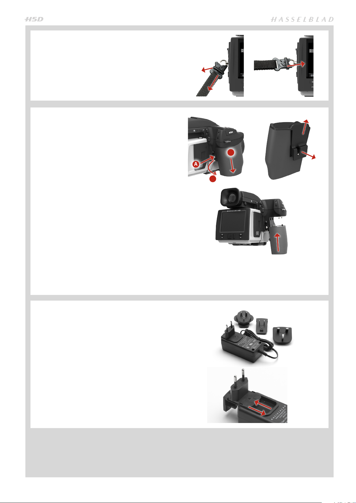
CARRYING STRAP
The carrying strap is attached by firstly withdrawing the
safety collar. The hook is then freed and can be attached to
the strap lug. Slide back the safety collar to ensure the hook
remains in the locked position between the small protruding
lugs. The collar is purposely a tight fit to avoid unintentionally slipping back and therefore might need some effort to
slide.
RECHARGEABLE BATTERY GRIP
The environmentally approved Battery grip Li-ion (3043356)
is the standard power source for the H5D camera. The H5D
requires a power supply for all actions as there is no mechanical reserve facility. When working untethered, it is
therefore advisable to keep a reserve rechargeable battery
grip at hand. As is the case with most batteries, problems
might be encountered when used in very low temperatures.
In this situation it is advisable to keep the reserve battery
in an inside pocket, for example, to maintain it near body
temperature (both sorts of battery grips are referred to as
the ‘battery’ in this manual).
FITTING AND REMOVING A BATTERY
The fitting and removing procedure is the same for both
types of battery grip.
C
A
B
Remove the battery from the camera by depressing the battery holder button (A) and simultaneously swinging the battery holder retaining lever (B) down until it stops. Pull the
battery downwards (C).
If you intend to store the battery separately from the camera
you should ensure that the safety cover is in place (to prevent short-circuiting). It snaps into place and is removed by
pulling outwards and upwards on the locking clip.
BATTERY CHARGER
The battery charger is supplied with a number of plug attachments to suit various types of domestic electrical sockets available worldwide. Other types of socket will require a
domestic socket converter.
Attach the chosen plug by sliding it into position as in the
diagram. Removal is by the reverse procedure.
Please note that the Battery charger Li-ion 2900 (3053572)
is designed for use with Battery grip Li-ion 2900 (3043356)
but can also be used together with the Battery grip re-
chargeable 7.2V Li-Ion (3043348) intended for H4D use.
Likewise, the older Battery charger for Li-Ion battery
(3053568) also can also be used together with the Battery
grip Li-ion 2900 (3043356) but requires 50% longer charg-
ing times.
To fit, hold the battery flat against the camera body and
aligning the two upper lugs with the slot, slide it back into
position as far as it will go. Swing back the battery holder
retaining lever until it clicks back into place.
20
Page 21
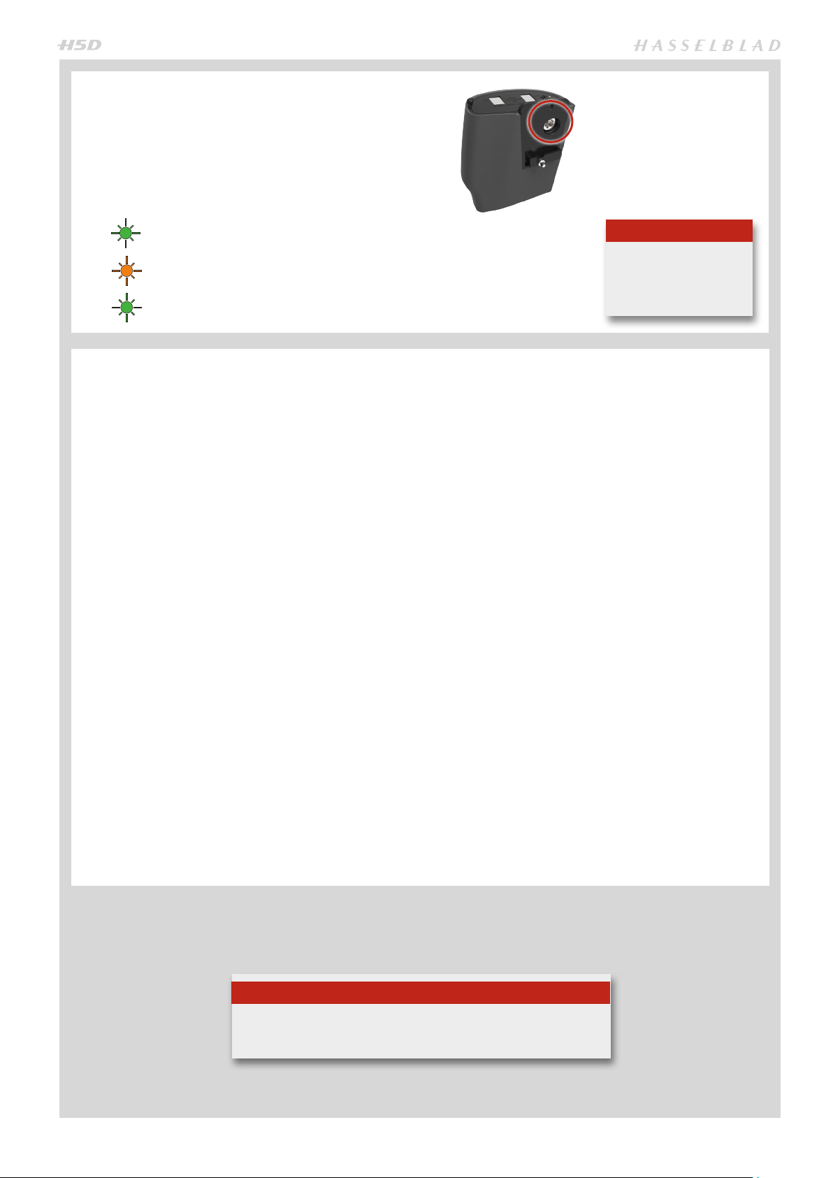
CHARGING THE BATTERY
With the battery removed from the camera, insert the jack
plug from the battery charger into the socket on the battery
grip. Insert the battery charger into a standard (100–240V~
/50–60 Hz) domestic socket.
During the charging procedure, the lamp on the charger
signifies the following:
Standby (no battery connected)
Charging
Ready
RECHARGEABLE BATTERY GRIP LI-ION/ BATTERY CHARGER LI-ION 2900
It can take about 6 hours
to load the battery completely the first time.
– PRECAUTIONS & GENERAL
• The battery should be charged for approximately 6 hours
before first time use.
• The battery must be charged at room temperature.
• Maximum battery capacity is reached only after the bat-
tery has been charged and discharged several times.
• Avoid frequent full discharges (a full discharge is signalled
by the appearance of the Replace battery warning on
the grip display). As the battery is a Li-ion type, it has no
‘memory effect’ of practical importance and therefore frequent recharges will cause no problems such as loss of capacity or poor performance. It is therefore better policy to
recharge the battery at very regular intervals, regardless
of use.
• Remove the battery if you intend to store the camera
for some while as it will eventually become completely
drained, even though the camera is turned off.
• The battery has an integrated ‘fuel gauge’ capability that
supports the Replace battery and Battery status functions
on the grip display. As with most Li-ion batteries, this capability should be occasionally calibrated, depending on
how much the battery is used. To do this, leave the camera
on (or use it), until the Replace battery warning appears.
Then, recharge the battery for 6 hours. This will improve
the accuracy of the measurements.
• When removing a battery from the charger and immediately replacing it with another, allow a few seconds to
elapse so that the charger can automatically reset for the
next charging procedure.
• It is perfectly normal for the battery to become warm
when being charged.
• A slight temporary loss of battery performance might
be noticed at very high or low temperat ures. Take the
appropriate measures if this is the case.
• If you do not intend to use the battery for a while, it is best
to store it at room temperature with an approximate 30
to 40% charge. You can check the percentage level on the
status screen.
• The battery should have a usable service life of around
400 recharge/discharge cycles.
• Connect the battery grip to the camera correctly.
• Keep the protective cover in place when not in use. (Short-
circuiting across keys in a pocket, for example, could cause
a fire risk).
• Do not immerse the battery grip in liquids.
• Do not incinerate the battery grip. Please recycle or dis-
card in an environmentally approved manner.
• Use indoors only (protect against moisture).
• Do not short-circuit the jack plug.
• Do not alter the charger in any way other than changing
the plug attachment.
Note
Tip
You can save battery consumption by changing the Display Off /Sleep
/Power Off settings as well as the brightness settings of the display.
21
Page 22
BATT E RY LI FE
Battery life is dependent on a number
of variable factors and therefore cannot be exactly predicted. If the camera is left in the active state instead
of Display Off or Sleep modes for long
periods, for example, then the battery
will become exhausted much faster.
A low camera battery state is indicated by a symbol on the grip display
and in the viewfinder. In addition, an
audible signal sounds.
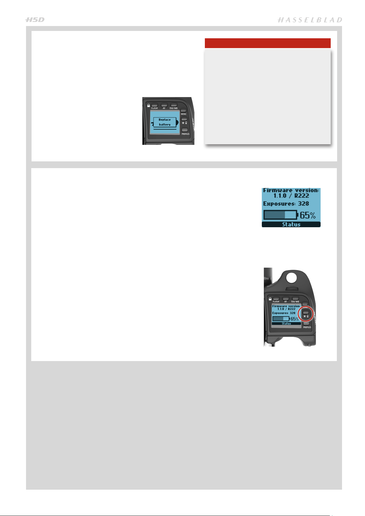
When the battery is almost completely exhausted, a warning message Re-
place battery will appear on the grip
display.
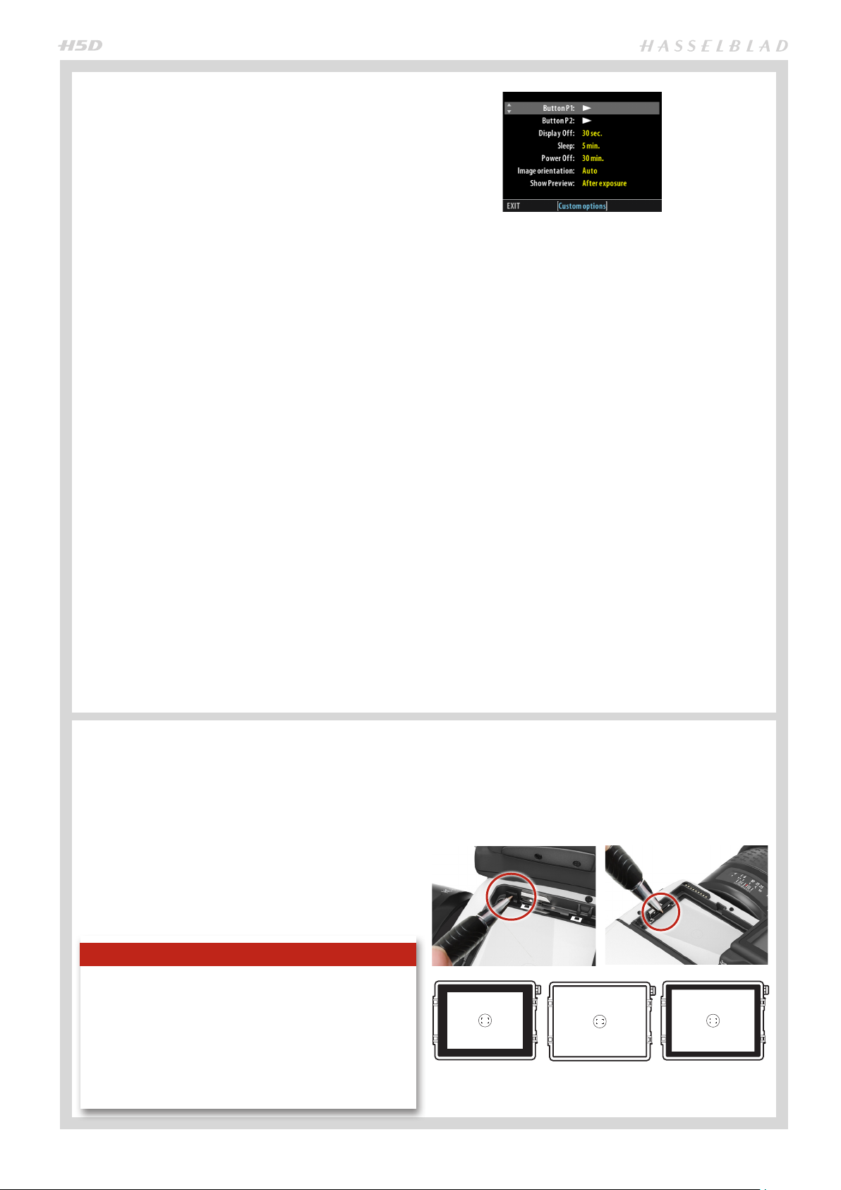
BATT E RY STAT US
An immediate full-screen information and battery status check appears on the
grip display by holding down the illumination/battery status button. This screen
displays:
• the rmware version
When the low battery message in the viewfinder
and the low battery icon on the grip appears,
the camera automatically enters a temporary power-saving mode. This is recognizable
by a slower pace for all the actions in a capture sequence. The camera actions also sound
differently.
This mode is designed so that you can continue
working for a while, even though the power remaining in the battery is too low for working in
the normal manner. Normal action automatically returns with a refreshed battery.
Note
• the number of captures taken since the last battery recharge / change.
• a rechargeable-battery status icon that provides a quick visual check as well as a
figure estimate in percent.
The information regarding the number of captures taken is intended to help you
make an estimate of the number of possible remaining captures according to your
way of working. For example, if you regularly browse a great deal when shooting
or you leave the camera in ON-mode instead of Display Off or Sleep modes, you
would naturally expect to drain the battery sooner than others who don’t. You
should soon be able to build up a picture of how you usually work and can therefore estimate that after X number of captures, you normally expect to be able to
take Y captures before the battery is exhausted (when working in a similar manner
in similar conditions).
The percentage information, however, provides another kind of estimate based
more on the amount of charge left in the battery rather than on your normal way
of working.
Remember that these are only estimates and that there are a number of factors
affecting remaining battery charge, ambient temperature for example, as well as
general practice.
22
Page 23
POWER MODES
The H5D can be set at three active modes − ON, Display
Off and Sleep. In these active modes, battery consumption
is least in Sleep mode and most in ON mode. Both the grip
and the sensor unit displays are dimmed accordingly. However, after a set number of minutes of complete inactivity,
the whole camera can automatically enter another mode
(custom setting) to conserve power (indicated by no visible
logos on either display).
ON
To activate the camera press the red ON.OFF button until
you see the start-up H5D logo appear on the grip display.
The logo is automatically followed by the main screen.
OFF
From the active screen, press (not click !) the red ON.OFF
button for a half second. All buttons (except the ON.OFF
button) remain ineffective, producing virtually no demand
on the battery. This is the normal mode when transporting
or storing the camera or where there might be a risk of inadvertently activating the camera. (However, remove the battery grip if you are going to store the camera for a period of
more than a few weeks).
In this mode neither the viewfinder display nor grip display
information is available.
SLEEP
SENSOR UNIT MENU > SETTINGS > CUSTOM OPTIONS >
SLEEP
In this mode the camera is in ‘power down’ mode and therefore reduces battery consumption. This mode is indicated
by the ready lamp glowing orange instead of green. From
this mode it will take a few seconds to re-activate the camera. Any of the buttons listed below will work.
The time intervals are: 5 minutes, 10 minutes and Never.
POWER OFF
SENSOR UNIT MENU > SETTINGS > CUSTOM OPTIONS >
POWER OFF
In this mode the camera is completely without power and
has to be started by pressing the ON button again - simple
reactivation is not sufficient.
AUTOMATIC SETTINGS
DISPLAY OFF
SENSOR UNIT MENU > SETTINGS > CUSTOM OPTIONS >
DISPLAY OFF
In this mode the camera turns off the grip and sensor unit
displays but remains ready to be immediately reactivated to
the ON mode.
The time intervals are: 10, 20, 30 and 60 seconds.
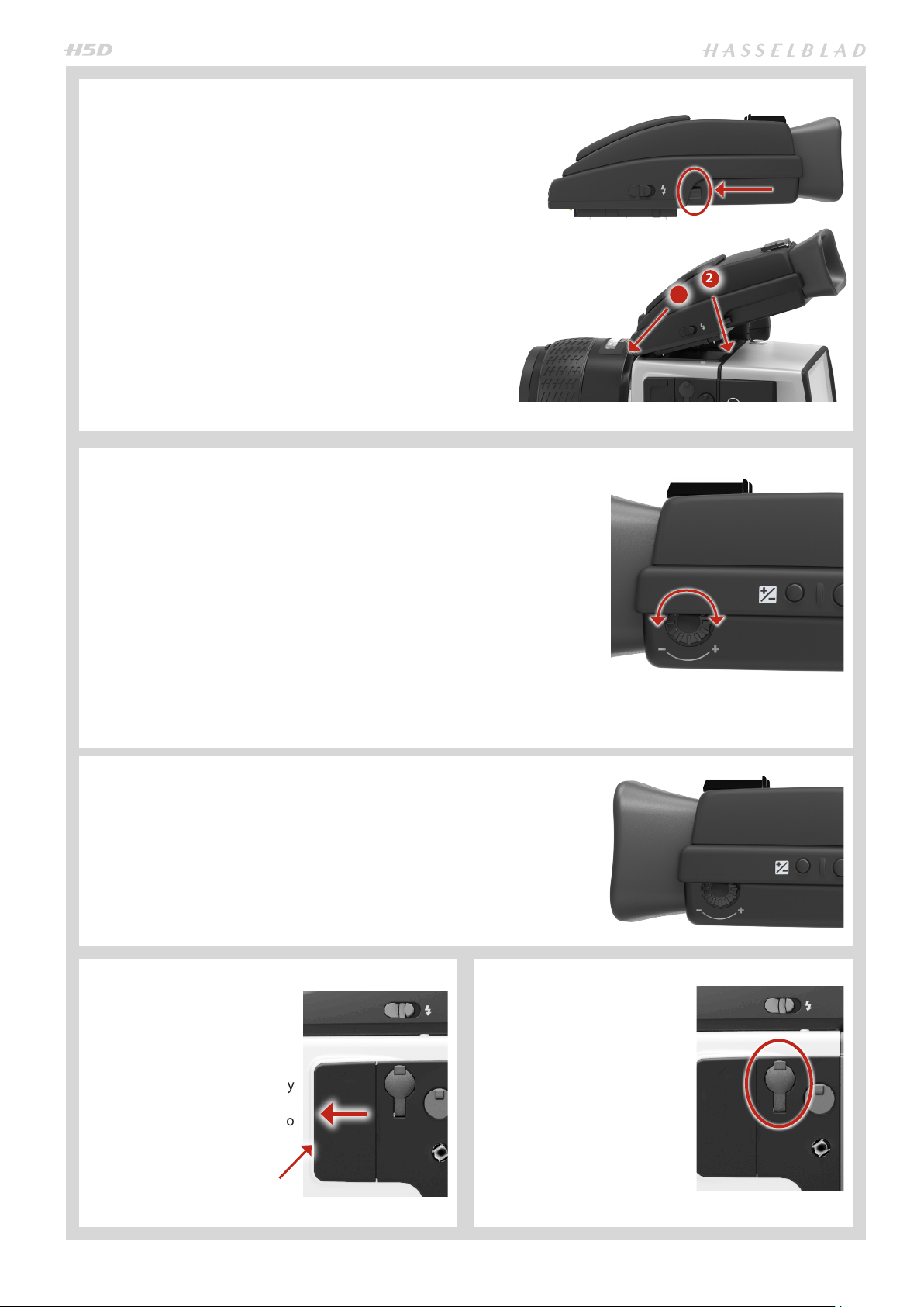
VIEWFINDER SCREEN
The H5D is fitted with a Spherical Acute-Matte D viewfinder
screen for extreme brightness, clarity and even illumination. An optional accessory screen with a grid pattern is also
available.
To change a viewfinder screen, remove the viewfinder to access the viewfinder screen. To remove the screen, place the
tip of a ballpoint pen or similar in the viewfinder screen removal lug and pull upwards. To replace the screen, position
the right side of the screen in place so that it sits correctly
in the recess. Place the tip of a ballpoint pen or similar in
The time intervals are: 30 minutes, 60 minutes and Never.
RE-ACTIVATION FROM DISPLAY OFF
OR SLEEP MODES
• press the shutter release button half way
• press the Stop down button
• click the ON.OFF button
• press the Mirror up button.
the viewfinder screen replacement indentation and press
downwards until the screen snaps into position. Try to avoid
touching either surface of the screen with bare fingers.
Note
Do not attempt to clean the screen by immersing it in water, or use any kind of cleaning fluid. If the screen becomes
damp, do not use hot air to dry it. Use a soft cloth on the upper surface only. Seek advice from an Authorized Hasselblad
Service Center if the screen becomes particularly soiled. Remember that particles or greasy marks on the screen might
impair the viewfinder image but have no effect whatsoever
on the recorded image
Viewfinder screens showing the difference in masking and composition
frame marking. Type varies according to sensor size. See under Accessories for other types (with grid pattern, for example).
23
Page 24
REMOVING AND ATTACHING THE
VIEWFINDER
To remove, grasp the viewfinder in the right hand and while
depressing the viewfinder release button, lift the rear of the
viewfinder up and away from the camera body.
To attach, hold the viewfinder at a slight angle and rest it
on the top of the camera. Slide the viewfinder forward until
the front locating pin is in position in the recess in the front
edge of the viewfinder screen aperture on camera body.
Press the rear part of the viewfinder firmly downwards until
it clicks into place.
Ensure that both sides of the viewfinder are seated correctly
and that it has been firmly attached and locked into position. Failure to do so could cause an intermittent malfunction if the databus interface connections between the viewfinder and camera body are not positively secured. Avoid
lifting the camera by the viewfinder alone.
EYEPIECE ADJUSTMENT
No corrective lenses are needed to adjust the eyepiece to suit most requirements.
The diopter range is from -5 to +3.5D. Eyeglass wearers can rapidly and accurately
change the settings according to whether they wish to wear eyeglasses for viewing or not.
2
1
Personal eyepiece adjustments can be carried out by pointing the camera at the
sky or similar smoothly toned area. While holding the camera in your left hand, you
can with your right thumb turn the adjustment wheel until the markings on the
viewfinder screen reach the optimum sharpness for your eyesight.
If you normally wear eyeglasses for distance viewing and intend to wear them for
camera use then do not remove them for the above procedure. If, on the other
hand, you prefer to remove your eyeglasses for camera work, then repeat the
above procedure without wearing your eyeglasses.
RUBBER EYE CUP
Two rubber eye cups are available for the H5D. The one supplied is suitable for users who do not intend to use eyeglasses when photographing. The second shorter eye cup is for
those who either prefer to position their eye further from
the viewfinder and those who wish to wear eyeglasses.
The eye cups can be rapidly changed by a Hasselblad Authorized Service Center.
ACCESSORY CONNECTION
There are two accessoryretaining screw threads (M5) as
well as a databus connector on
the left hand side of the camera
body, protected beneath a cover.
The cover can be removed by
firstly lifting the left hand edge a
little and then sliding the cover to
the left, as in the illustration.
PC-CONNECTOR
A PC connector for non TTLflash synchronisation is located
on the left side of the body. It is
protected by a captive rubber
plug.
Lift this edge of the cover first
24
Page 25
PROTECTIVE BASE PLATE
To remove the protective base plate, lift the securing catch while pushing the plate towards the lens. To attach it again, slip
it over the camera foot until it stops and the securing catch snaps into place.
USING COMPACT FLASH MEMORY CARDS
When using a compact-flash card, the H5D is completely self- contained. No additional wires or connectors need to be attached. The recommended type is UDMA/type
4 /60MBs (400x) or better. Please see the Appendix in this manual for a list of recommended cards.
The H5D is shipped with an 8GB (or larger) compact-flash card, which is capable of
holding approximately 50 − 100 captures (according to model). Lossless compression
is applied to the images, so the actual size of each capture can vary, thereby affecting
the total number of shots you can fit on the card.
All cards should be formatted in the sensor unit before first-time use!
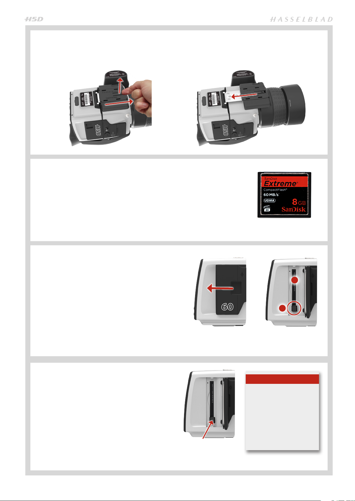
INSERTING A CF CARD
1. Open the CF card slot cover on the sensor unit by inserting a thumb in the recess and then sliding it to the left.
2. Behind the cover, you will see a slot for the card (A) and a
release button (B) below the slot.
3. Hold the compact-flash card so that the connector holes
face into the slot and you can read the brand label when
you are behind the camera. Gently press the card into
the slot. If you encounter resistance, it might be because
you are holding the card backwards or upside down.
4. If the card can be easily inserted nearly all the way into
the back, then you are inserting it correctly. Press the
card another couple of millimetres firmly into place.
5. Close the slot cover and slide it to the right to lock it.
REMOVING A CF CARD
1. Open the CF card slot cover on the sensor unit.
2. Press the release button a little way in and then release
it so that it extends a little out from the slot.
3. Press the now extended release button all the way back
into the sensor unit again. Some force is required. As you
do this, the card will be pushed out a few millimetres.
4. Grasp the card and pull it away from the sensor unit.
5. Close the slot cover shut again.
A
B
Note
Do not remove a CF card
from the sensor unit if the
‘ready’ light is ORANGE !
All files on the card may
become corrupted (and
consequently lost) if you do
so and new formatting may
also be necessary.
25
Page 26
FORMATTING CARDS
The camera is only able to read and write to storage media
that have been formatted correctly. New cards sometimes
have no formatting, or you might want to convert a card that
is currently using a format that the camera cannot read. In
either case, you must reformat a CF card in the sensor unit
for H5D use.
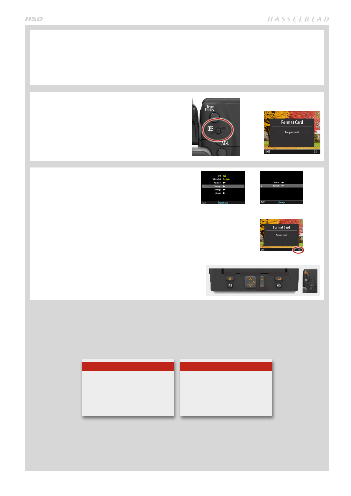
FORMAT BUTTON
Press the Format button on the camera grip. It is purposely
recessed to avoid unintentional use, so use a ball-point pen
or similar. A prompt is displayed on the sensor unit for confirmation.
FORMAT VIA SENSOR UNIT
SENSOR UNIT MENU > STORAGE > FORMAT > DIALOGUE
1. Press MENU.
2. Navigate to Storage (use the Rear scroll wheel or the
Navigator).
3. Navigate to Format (use the Front scroll wheel or the
Navigator).
4. Navigate to Format dialogue (use the Front scroll
wheel or the Navigator).
5. Confirm by pressing OK (Display button).
There are two ways to format cards. The quickest way is to
use the Format card button on the grip but if you prefer, you
can also use the menu on the sensor unit.
Note
Only UDMA/type 4/60MBs (or 400x)
cards or better are recommended for
H5D use.
See full list in Appendix in this
manual.
Navigator Display
Menu
Zoom
Note
All CF cards should be formatted in
the sensor unit before first-time use!
26
Page 27
SENSOR UNIT – INTRODUCTION
The captured image is temporarily stored internally on a CF
card in the sensor unit or onto a computer hard disk when
tethered using Phocus. True to the modular design, the sensor unit can be removed and attached to a large format /
view camera (see later section in this manual) for both tethered and untethered use.
When attaching and removing the sensor unit, pay particular attention to the sensor area. The sensor itself is covered
and protected by a glass IR filter but take great care when
handling.
If you scratch or mark the filter in any way, it will show up on
every shot. Replacements are expensive so treat the glass
surface with at least as much care as you would a lens. The
sensor itself is not accessible for any kind of cleaning or
maintenance by a user. Do not attempt any such action as
you will almost certainly damage it irreparably. When storing separated from the camera, always ensure you use a protective cover.
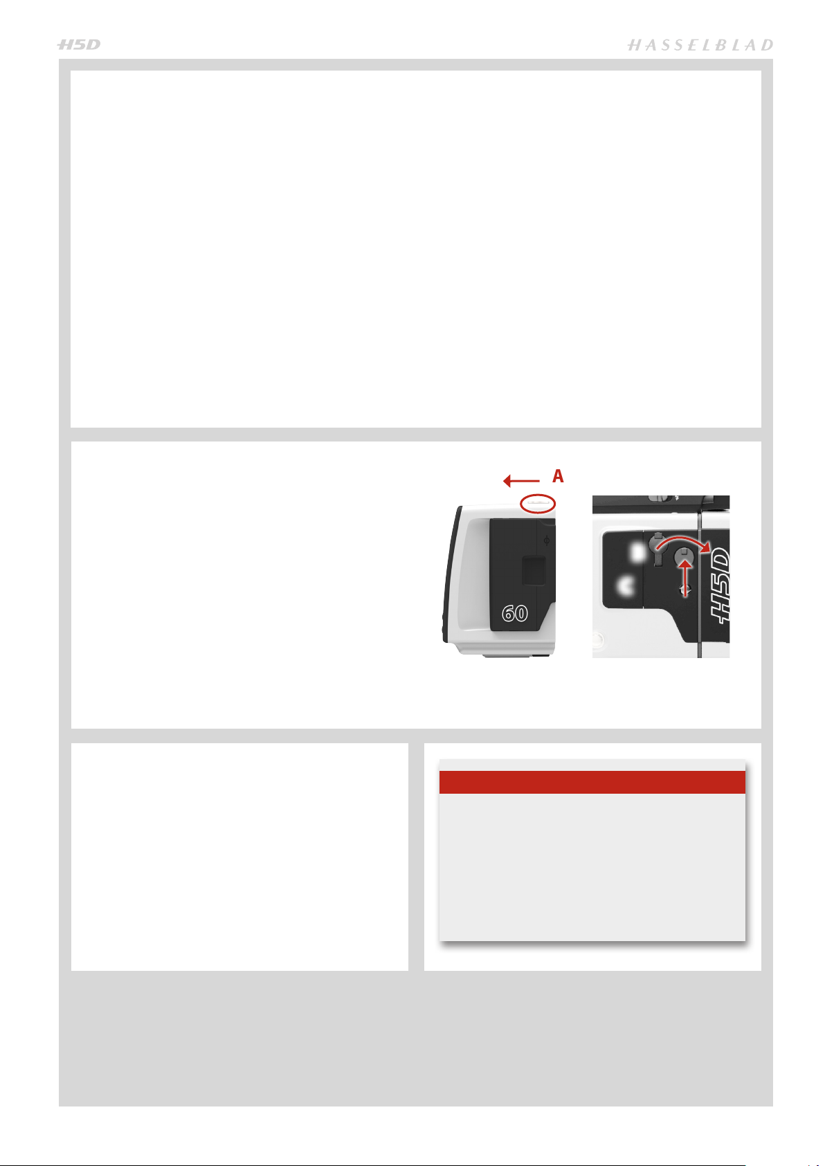
REMOVING AND ATTACHING THE
SENSOR UNIT
1. Remove a FireWire cable if connected.
2. While pushing the safety catch towards the rear of the
camera A, rotate the sensor unit release button to the
right B, and while maintaining that position press the
centre of the button firmly inwards towards the camera
body C to finally release the magazine.
3. Clean the outside surface of IR filter by using clean
compressed air (see warning above first). If this is not
enough, then use one of the procedures outlined below.
5. Reattach the sensor unit to the camera immediately
after cleaning to check results.
6. If you still see spots on your shots after you have cleaned
the outside of the infrared filter, then you may have dust
either on the inside of the IR filter or on the CCD itself.
As is the case with all electronic devices pay extra care when
working in damp en vironments and avoid damp conditions
for storage.
With untethered use, the management of captures is
handled by the sensor unit. In tethered use, captures are
handled and stored by the computer and can be visually
checked in Phocus immediately.
Settings are made entering the sensor unit menu using the
buttons on the unit. Grip scroll wheels can also be used, if
selected as a function option. Some sensor unit information
is also visible on the grip display, the viewfinder display and,
when tethered, Phocus.
Remember to check settings before each shoot. It is easy to
forget small adjustments you might have made the time before. You might want to consider using the profile function
to make a one-button-press resetting of important functions for your particular regular situations.
A
B
C
CARE AND MAINTENANCE OF SENSOR
UNIT
• Always replace the protective CCD/lter cover when
the sensor unit is not mounted on a camera.
• Do not touch the exposed CCD/lter with your ngers.
• Keep all foreign objects away from the camera open-
ing when attaching or removing a sensor unit.
• Store the sensor unit away from moisture and excessive heat.
• Protect the sensor unit from impact.
Note
Time & Date settings on the sensor unit (which are included with files and folder labels) are updated automatically through a FireWire/Phocus connection. These
settings are retained for about two consecutive weeks
by a small rechargeable cell that is automatically recharged by the main battery or FireWire with regular
use. If problems occur, charge the cell by leaving the
sensor unit turned ON for around 12 hours.
27
Page 28
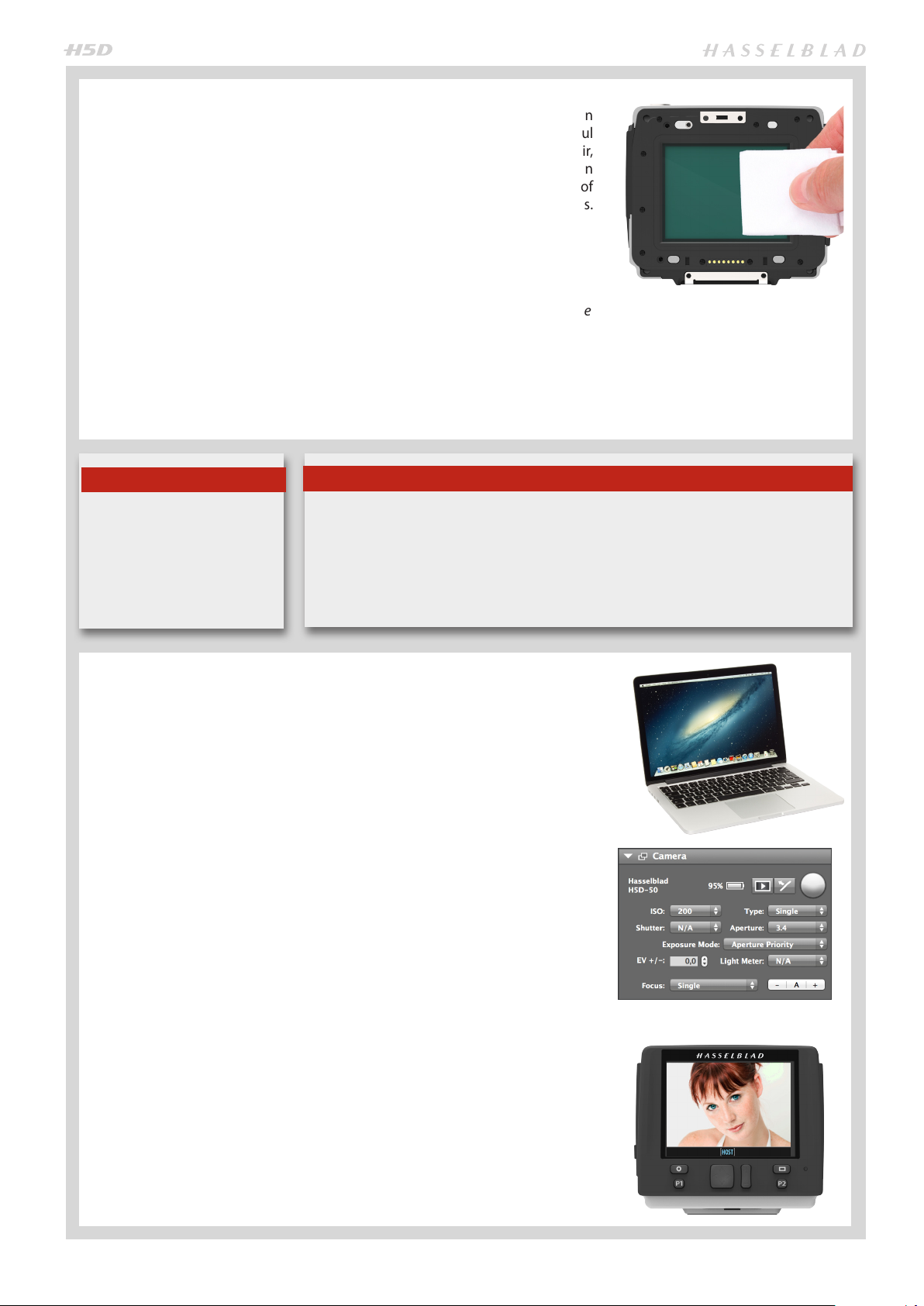
CLEANING THE SENSOR FILTER
If you see dark or colored spots or lines in your images, then you may need to clean
the outer surface of the sensor unit’s infrared (IR) filter. In most cases, the careful
use of compressed air will be adequate though if you use canned compressed air,
read the instructions very carefully before use to avoid spraying impurities or even
ice on the filter! Sometimes, however, small particles will get stuck to the surface of
the IR filter, requiring for a more thorough cleaning, involving either fluid or wipes.
1. If compressed air did not remove all the problems on the filter, then use an
E-wipe.
2. Tear at the notch to break seal. Remove E-wipe from its packaging and fold
the tissue to match the width of the IR filter.
3. Apply firm pressure using two or three fingers at the edge of the wipe to ensure
an even, firm contact with filter surface. Wipe the surface in one unbroken
motion.
4. Finally check if the IR filter has been properly cleaned either by visual inspection or by mounting the sensor unit to the camera and making a test capture.
If further cleaning is needed, repeat cleaning procedure.
Note
Do not use same side of the ewipe twice as you will be likely
to re apply any particles removed in the first pass.
TETHERED TO A COMPUTER WITH
If you still see spots on your shots after you have cleaned the outside of the infrared
filter, then you may have dust either on the inside of the IR filter or on the sensor itself.
However,
do so!
If dust manages to get between the IR filter and sensor, it can only be removed at the Hasselblad factory. Contact your Hasselblad dealer or Hasselblad Service Center for assistance.
never attempt to remove the glass filter – you will probably ruin the sensor if you
Note
PHOCUS RUNNING
When tethered to a computer, you can control many camera functions using Phocus software. All captures are saved as 3F files (as opposed to 3FR files from a CF
card) and can be immediately exported to other formats if desired.
CONNECTING TO A COMPUTER
To connect to a computer, attach a FireWire cable from the FireWire port on a computer to the port on the side of the sensor unit. The port is protected behind a
hinged cover.
When you are connected to a computer, the following applies:
• The destination medium and location are controlled from Phocus.
• All exposure settings, including ISO, aperture and exposure time, are controlled
from Phocus if you choose to expose from Phocus. In addition extra tools such
as Live Video, remote focus control etc are available. See Phocus user manual
for full description.
• The sensor unit will take power from the FireWire cable if it is available (not all
computers can supply power, notably PC laptops). This will help conserve the
battery power. However, you must still have a charged battery connected as
the camera body needs it in order to operate.
When initiating a shot from Phocus, the computer sends a signal to the sensor
unit, which triggers the shutter (and strobe/flash, if any). The back then sends the
capture over the FireWire connection to the computer, where it is displayed on the
computer screen and saved as a 16-bit 3F file in the currently selected folder on the
computer hard disk.
When tethered, each capture also appears as ‘Host’ on the sensor unit display.
Please note that the buttons on the unit have no function in this mode.
28
‘Camera’ tool in Phocus.
Page 29
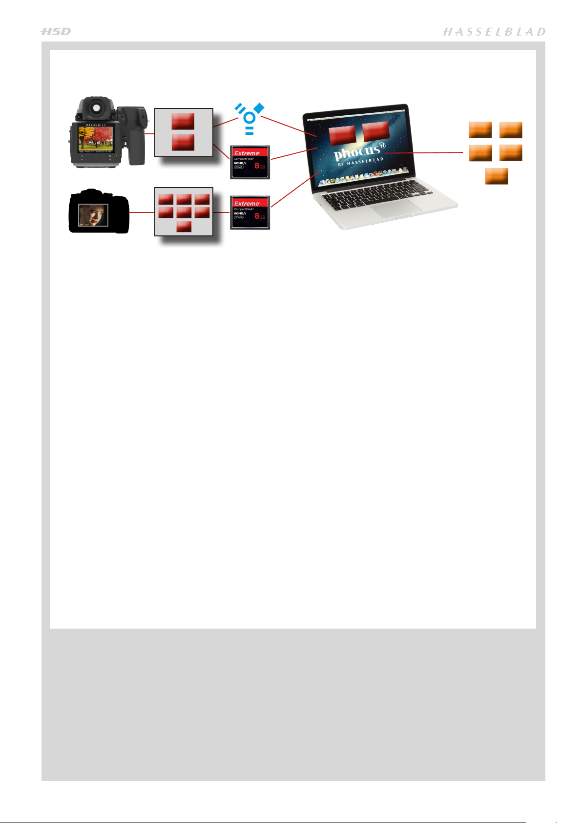
HASSELBLAD CAPTURE FILES, PHOCUS & ADOBE/APPLE SOFTWARE WORKFLOWS
ere
3FR
JPEG
.fff
.jpeg
PSD
JPEG
TIFF
DNG
etc.
.nef
.cr2
.mos
.dng
.tiff
.jpeg
etc.
The H5D can capture files and store them as Hasselblad RAW format files or Hasselblad RAW + JPEG formats simultaneously.
Hasselblad RAW files are initially stored in the 3FR format which is a proprietary Hasselblad format for the temporary storage
of captures. A 3FR file contains the complete digitized raw image exactly as it was captured by the camera. 3FR information
requires further computing power (typically by way of Phocus) to obtain complete development. If developed in Phocus,
3FR files become Hasselblad 3F files – denoted by each file now bearing the suffix “.fff”. If developed by other RAW processors, the 3FR files are not converted to 3F but can be exported directly to TIFF, PSD etc according to requirements.
However, when working tethered – which necessitates using Phocus – 3FR files are automatically processed and stored in
the background on a computer appearing as 3F files on the hard disk ready for selective adjustment and export. 3FR files
stored on a CF card can be processed to completion using:
• Hasselblad Phocus
• Adobe Camera Raw / Lightroom
• Apple Aperture
To sum up, capture files can be stored as 3FR files (from a CF card) for later processing in Phocus or other software, or they
can be stored as 3F files (as a result of tethered shooting or 3FR files processed and converted in Phocus). In all cases if you
keep the original 3FR/3F files, you will also retain the possibility of reprocessing them in the future in later versions of Phocus
or other software to take advantage of eventual improvements and developments.
Note that using Phocus is the most comprehensive method. The Phocus and Adobe methods can produce almost identical
results (in most cases, but not all) regarding RAW conversion so it is a matter of personal choice regarding which method
would best suit your preferred ways of working. Alternatively you can use Apple Aperture though you should take note that
the benefits of DAC and HNCS etc, will be lost in this case.
Mixed formats
Phocus can also process most other capture formats, generic and proprietary. This means you can include other formats in
your normal Phocus workflow if you choose. Or if you prefer, you can include Hasselblad files in Adobe / Apple workflows
as stated above.
29
Page 30

PHOCUS
Phocus is the capture processing and file management application aimed primarily at Hasselblad 3F
file handling. Phocus Mobile offers remote viewing
and control when shooting tethered while Phocus
Quick offers a very rapid and simplified file processing capability.
Phocus allows the extraction of the most detailed files from
the world’s most advanced cameras to your desktop in a professional and efficient manner.
Phocus works the way that photographers work and provide
serious photographers with a well thought out, and intuitive
workflow, designed to provide maximum power and options
with a minimum of effort. Phocus produces ground-breaking
new levels of image quality and technical precision and when
combined with the world’s finest optics and image sensors
the result is exactly what you would expect from Hasselblad –
simply stunning image quality.
FEATURES IN PHOCUS
Ultimate Image Quality
· Hasselblad Natural Color Solution (HNCS)
· Sophisticated lens corrections for H and V system lenses
(DAC)
Specialized Tools
Ultimate Image Quality
Phocus combines with Hasselblad Natural Color Solution
(HNCS) and Digital Auto Correction (DAC) to provide ultimate
image quality in every image you create. With Phocus, the
moiré that can occur on even extremely high-resolution images is effectively removed automatically and directly on the
raw data, leaving image quality intact and saving hours of tedious post-production work.
Tethered shooting is also very smooth with Phocus Remote
camera controls providing a number of remote functions,
such as remote focusing, live view, aperture and exposure
time controls, etc.
· Advanced Tethered Camera Controls
· Phocus Mobile *
· Live Video
· Scene calibration & reproduction tools
· Leading edge Moiré removal
· Highlight recovery, shadow fill, clarity and dust spot
removal tools
· Camera Configuration
plus:
· Easy-to-use interface
· Extensive customization options for individual work-
flow scenarios
· Import/Export of Image Adjustments, Keywords, Workflow settings etc.
· High quality printing
· Slide show
· RAW file support from more than 150 DSLR cameras
· License free software (unlimited installations - no regis-
tration issues)
Any File from Anywhere!
Phocus allows you to import your files, RAW or otherwise and
work in the same powerful and intuitive processing environment, no matter where your files are coming from. This means
that you can browse, handle, adjust, and process all kinds of
RAW and non-RAW formats.
Phocus Mobile
Phocus Mobile is available for the iPhone®, iPad® and
iPod Touch®. It enables you to connect wirelessly to a
computer running Phocus and to remotely browse your
high-resolution RAW, JPEG and TIFF images.
This provides a handy solution for working with clients
in the studio, enabling each person to view images on an
individual iOS device, rather than all gathering around a
single computer.
Phocus Mobile also allows users to remotely operate
and trigger a tethered camera, giving control of many
parameters, all neatly presented in a virtual camera display. This feature is very convenient for remote control
of the camera when it’s located in a difficult-to-access
position. Phocus Mobile is available for free download
at the App Store.
Phocus Quick
Phocus Quick allows a preview of images from camera
to screen at the touch of a button. Your original images
(in RAW format) remain on the memory card and can be
backed up automatically if you wish. Either way, you can
view and review in Phocus Quick and still go back later
and fine-tune your images. The perfect combination of
ease of use and peace of mind! Phocus Mobile is available for free download from the Hasselblad website.
Phocus supports RAW files from more than 150 cameras, including Canon, Nikon, Leica, Sony, Fuji, Olympus, and so on**,
as well as the most common file formats such as TIFF, JPEG,
DNG, and PNG, making it easier than ever to work as you see
fit, not as your camera dictates.
* Phocus Mobile is available for download on the App Store.
** Full list available at http://www.apple.com/aperture/specs/raw.html
30
Page 31

LENSES &
FOCUS MODES
Photo: Joac him Schmeisse r © / Hasselblad Mas ters
31
Page 32

ATTACHING A LENS
Remove the front protective cover
on the camera body by depressing
the lens release button and keeping it depressed while turning the
cover counter-clockwise. Remove
the rear lens cap by unscrewing it in
a counter-clockwise direction. Align
the index on the lens with the index
on the camera body and rotate the
lens clockwise (bayonet fitting) until
it clicks into place.
REMOVING A LENS
Depress the lens release button and
keep it depressed while rotating the
lens counter-clockwise until it stops and
lift it out. Replace protective caps on the
lens immediately and on the camera
body if necessary.
If you try to rotate the lens before you
press the lens release button, it might
lock. In this case, rotate the lens clockwise a little first and then re-attempt removal with the correct procedure: button first, then lens.
FRONT LENS CAP
Front lens caps are released for removal and attachment by inserting
a thumb and index finger into the
recesses and pinching in the direction of the arrows.
SHUTTER AND APERTURE CONTROL
In manual mode both the shutter and aperture are electronically controlled and are adjusted by the scroll wheels
on the grip. There are no separate manual setting rings on
the lenses or camera body.
The chosen settings are displayed both on the grip display
and in the viewfinder display. See under Light Metering &
Exposure Control / Exposure Method for a complete explanation.
LENS SHADES
All lenses are supplied with lens shades that additionally provide extra protection
for transport and storage when mounted in reverse. Lens shades have a bayonet
fitting and are turned clockwise into place after ensuring the index on the lens
shade aligns with the index on the front of the lens. When mounted in reverse,
they are attached by matching the indexes and turning clockwise.
FILTERS
Filters have a screw thread fitting
(67 / 77 / 95 mm, according to lens)
and are screwed clockwise into
place. As there is no rotation of the
front section of the lens when focus
is changed, filters do not rotate either. This is particularly useful when
using polarizing or graduated filters
where the orientation is normally
critical.
FOCUSING DISTANCE CALCULATION
There are two distance scales (in feet and metres) visible
through the window on the upper part of the lens barrel.
The focusing distance is read off the chosen scale from the
central lens index.
Central lens index
32
Page 33

STOP DOWN / DEPTH-OF-FIELD PREVIEW
A visual depth-of-field preview can be made by depressing the STOP DOWN button while viewing the image in the viewfinder.
Depth-of-field can be calculated as follows:
1. Focus the lens as required.
2. Make an exposure reading (auto or manual) and note the aperture setting.
3. Find the markings on either side of the central index that correspond to the
chosen aperture.
4. From these two markings, read off on the required lens distance scale the two
corresponding distances.
5. The depth-of-field (at that particular aperture and focus setting) will be the
area included between these two distances.
In the example given here, the focusing distance is set at nearly 3 metres. At an
aperture of f/22, the depth-of-field would therefore extend from just over 2 m to
approximately 4.5 m. Note that depth of field is not an absolute. Perception of it
depends on several factors and so it should be seen only as a rough guide.
INFRARED FOCUS SETTINGS
As infrared rays form an image at a different plane to that formed by visible light,
the normal focus settings do not apply. Proceed as follows in manual focus mode:
1. Focus the lens in the conventional manner until satisfied.
2. Note the distance setting against the central lens index.
3. Re-align this distance setting against the infrared mark (coloured red) instead
of the central lens index.
Alternatively if you have already calculated the required distance, you can make
a manual distance setting by using the distance scales together with the infrared
mark instead of the central lens index.
For specialists, please contact your Hasselblad dealer for information about sensor
units adapted solely for infrared photography.
FOCUS ASSIST
As well as the conventional view on the focusing screen to ensure a sharp image,
the H5D also features an LED focus assist capability appearing as two arrowheads
to the right of the viewfinder display (except for lenses with a maximum aperture
of f/6.7 or smaller). The arrowheads provide confirmation of a precision focus setting and are a useful aid when making a setting with eyesight alone.
Manual focus setting
When the left arrowhead alone appears it means the focus setting is too far beyond the chosen distance (the area framed within the central zone in the viewfinder) and when the right arrowhead alone appears it means the focus setting
is too close. Focus is correct when both arrowheads appear together. If the focus
cannot be established, then both arrowheads flash.
Automatic focus setting
Focus is correct when both arrowheads are visible together. Focus is incorrect if
only one arrowhead is visible. If the focus cannot be established, then both arrowheads flash.
Lens focus setting too
far beyond the distance
of the subject framed by
the central section in the
viewfinder
Focus setting too close
for the distance of the
subject framed by the
central section in the
viewfinder
Focus setting correct
33
Page 34

Note
Note
Some lenses have extra characteristics that require further
explanation. For example, the autofocus range on the HC
4/120 Macro lens can be limited by a specific setting on the
camera allowing for near range, far range or full range. This
only appears on the grip display together with that particular
lens.
Further information can be found in the "H-system Lenses &
H-system Lens Accessories" booklet that accompanies each
lens. The booklet can also be downloaded from the Hasselblad website.
Also, see note here regarding HCD lenses!
Note
Lens corrections can be applied when captures are imported into Phocus. Guided by the information in the metadata
included with each individual capture, the DAC (digital lens
correction) tool uses lens-model specific calculations to adjust
for chromatic aberration, distortion and vignetting. Not only
model specifications but also capture parameters are taken
into consideration for analysis.
This extremely capable refinement of captures should not be
overlooked when processing files! See Phocus user manual for
details.
HCD lenses were formulated for use with the smaller size
sensors in the H-series, resulting in a reduced coverage for
the larger sensors used in 60 Mpix models. So, if you use HCD
lenses, be aware of the restrictions (vignetting and diminished
quality at the edges).
As notification of this situation, an auto crop function is
employed and an HCD crop icon appears on the right hand
side of the viewfinder display when an HCD lens is fitted.
When in Phocus, however, the auto crop function can be
turned off in Preferences if you wish.
Tip
For users who prefer manual focus control but would like the
benefits of autofocus, one method is to set the AE-L button (or
any customizable button) to AF (Single) drive.
The main subject can then be centered and the AE-L pressed,
to ensure correct focus. The camera reverts immediately to
manual focus control when the button is released.
Therefore, you can recompose the picture without having to
maintain pressure on the release button in order to retain the
newly automatically made focus setting (AF-T can also be
used).
Tip
The True Focus function can also be combined with other
autofocus modes for specific situations.
Tip
To expand your range of lenses, consider using a CF adapter
to allow you to use most of the lenses from the Hasselblad Vsystem.
Note
The autofocus function is not possible with certain combinations of lenses and accessories. However, a warning is displayed which disappears after confirmation.
34
Page 35

MANUAL FOCUS
There is both a Manual focus mode setting and a manual override capability.
Manual focus is a specific setting that you actively make, whereas manual over-
ride is always available as a temporary override of an autofocus setting.
In Manual focus mode, focusing is carried out by rotating the focusing ring in the
conventional manner. The focus setting remains until changed as with a conventional non-autofocus lens. This means that pressing the shutter release button will
not activate a focus setting change as it does in autofocus. To change back to autofocus, you must make a new setting (by pressing the AF button and choosing
AF S or AF C).
With manual override in autofocus mode you can manually alter a focus setting
that has been made, by rotating the lens barrel in the conventional manner and
without having to change modes. As long as the shutter release button is kept at
the half-press position, the new focus setting is maintained. By releasing the pressure on the shutter release button and pressing again, the autofocus function is
immediately reactivated.
AUTO / MANUAL FOCUS SETTING
1) Press AF.
2) Turn the FRONT scroll wheel to select Single Shot, Continuous, Tru e
Focus or Manual as required.
3) Press SAVE.
AF
Front scroll
wheel
SAVE
Natural friction is inherent in the design to purposely reproduce the secure feel of a
com pletely manual lens.
Please note that when focusing manually, the infinity and closest distance marks
on the lens scale can appear to be positioned beyond the central index. This is only
an apparent effect and does not change the focusing range of the lens.
AUTOFOCUS
Autofocus mode can be either Single Shot or Continuous and is activated
by pressing the shutter release to the half-press position. Its operative range is
from EV1–19 at ISO100. The point of focus is determined according to the vertical
and horizontal areas (see illus) within the central rectangular zone on the focusing screen. When light levels are too low or the contrast of the subject is too low,
auxiliary illumination (situated on the top of the grip) is automatically activated if
desired. The operative distance is approximately six metres from the camera. Alternatively, a suitable attached flash unit that has a similar facility (a Metz 54/70, for
example) can also be used instead. This feature can be altered in settings (Custom
options #16/AF assist light).
True Focus is also classified as an autofocus function and is normally activated by
its own button on the grip. See later section.
MANUAL OVERRIDE IN AUTOFOCUS
MODE
Manual override is always possible in automatic focus mode
without any need to make a new setting; just rotate the focusing ring in the conventional manner. As the lens barrel
does not rotate in autofocus mode, you can hold the focusing ring for instant manual adjustments as you would with a
conventional lens. However, to retain the new manual focus
adjustments, you must maintain the pressure on the shutter release button. You can instantly return to the automatic
focusing mode by releasing the pressure on the shutter release button first and then pressing the release button halfway again.
The instant manual override function produces a convenient
way of working. You can take advantage of autofocus while
retaining an instantly adjustable manual focus check if preferred for pin-point accuracy without making any changes
in the settings.
AUTOFOCUS OVERRIDE IN MANUAL
MODE
See the following section for a description of how to use the
advantages of a rapid autofocus check while remaining in
Manual mode.
35
Page 36

SINGLE SHOT
At Single Shot setting (AF S), the shutter release will be blocked until the camera
finds the optimum focus setting. This ensures that no captures can be made that are
not finely focused. However, this delay will normally be only a fraction of a second in
good lighting conditions with a clear focusing pattern.
Note though that in this mode the lens will focus at a distance and will remain focused at that distance while pressure remains on the shutter release button. In this
way, you can focus on a nearby object for example, temporarily positioned within
the focusing zone on the viewing screen and then without releasing pressure on the
shutter release button, recompose knowing that the focus remains on the object chosen even though it is now outside the focusing zone. Releasing the pressure on the
shutter release button and pressing again half way would now change the focus setting to the distance of the object within the focusing zone.
See Manual override in autofocus mode for a useful way of working with manual and
autofocus settings in a combined manner.
CONTINUOUS
At Continuous setting (AF C), the shutter can be released rapidly before the lens
is focused in order to capture a split-second shot (in Single Shot, a capture cannot
be made until the camera has had time to focus). However, the camera will continue
to focus if a moving subject is within the focusing zone or if you recompose, even
though the shutter release button is half pressed.
One method to exploit this feature when photographing in a rapidly changing situation is to keep the shutter release button pressed down. In this way the lens focuses
constantly (according to the focusing zone) and by momentarily releasing the pressure on the shutter release and then immediately pressing again, you minimize the
amount of time needed for the lens to check focus, thus ensuring a split-second shot
at optimum focus.
TRUE FOCUS
The True Focus setting (AF T) is generally used in specific
circumstances to automatically correct for camera angle/focus setting discrepancies but it can also be combined with
other autofocus settings.
To be able to exploit True Focus correctly, a few impor-
tant points should be studied in order to obtain a full understanding of how and when to use it. Basically, there are
four variables to pay attention to listed below: (a) proximity of camera to subject, (b) focal length of lens, (c) aperture
setting and (d) movement of camera and/or subject after
setting. The closer you remain to the ideal situation with
regard to these variables, the more noticeable the effect of
True Focus will be.
• The closer you are to the subject, the worse the original
problem becomes. Consequently, the need for True Fo cus solution becomes greater and its application thereby
becomes more noticeable.
• Short focal length (wide-angle) lenses naturally decrease
camera to subject distances and therefore, following the
point in (a), produce a greater need for True Focus adjust-
ments.
• Smaller apertures increase the depth of eld and there-
fore would lessen the need for a True Focus solution.
However, smaller apertures produce a different visual effect, so True Focus therefore allows the exploitation of
the shallow depth
of field (produced
by larger apertures)
without the fear of
unwanted focus restrictions.
• The calculations in-
volved in True Focus use, amongst other things, camera
to subject distances to calculate the required amount of
adjustment. It therefore follows that if the camera or the
subject move after the initial setting has been made, the
calculations will not be applicable anymore. So, to ensure
the optimum correction, both the photographer and the
subject should restrict movement as much as possible.
Please note that with some lenses (particularly longer
length lenses) just a few centimeters movement can essentially ruin the result.
True Focus can be used with longer lenses, smaller apertures
etc but the further you come from situations similar to the
‘ideal’ as described above, the less the effect will be until it
has no visible effect at all. Please remember that although
True Focus can noticeably improve a demanding shoot it will
only work effectively in the specific circumstances it was designed for.
36
Page 37

TRUE FOCUS AND ABSOLUTE POSITION LOCK
The obvious situation that would most benefit from using True Focus would be a fashion shoot with a fairly wide angle
lens at a large aperture setting and where the central area of the image is clothing while retaining focus on the model's
face. Ideally, a fairly controlled and static flow should be planned on (this means a change of pose by the model should take
place only after captures and the photographer must resist crouching down, or leaning forwards or backwards too much
before capture).
With the lens at its widest aperture setting, a normal autofocus setting is made on the model's face (A), and the camera
focus locked. The composition is then changed to include more of the clothing (B), but the locked focus setting now extends
beyond the model's face at (B) according to the laws of geometry. This will naturally result in an image where much of the
subject closest to the camera and the model's face will be unsharp. Solutions involving manual focus/focus lock/ resetting of
multi-point sensors are distracting to workflow and prone to error. Making a True Focus setting at (A) will ensure that focus
is automatically adjusted in accordance with the change of camera angle.
True Focus uses yaw rate technology and by way of the Absolute Position Lock (APL) processor, logs camera movement as
the basis for an extremely rapid compensatory focus reset without any shutter lag. The H5D’s firmware then further perfects
the focus using the precise data retrieval system found on all HC/HCD lenses.
A
A - ca. 2.5 m
B - ca.2.5 m
Distance when camera perpendicular ca. 2.4 m
B
A normal autofocus setting is made on the
model's face and locked.
The focus setting is approximately 2.5m.
A
B
When the camera is swung back down, B,
the locked focusing distance of 2.5m, according to the laws of geometry, extends
beyond a perpendicular line drawn down
from the face, creating unsharpness.
B
A
If a True Focus setting instead of a normal autofocus setting is now made at A and
the composition changed back to B again, the camera will automatically calculate
and adjust the focus of 2.5m to approximately 2.4m, which is the actual camera to
perpendicular distance. The model's face is now sharp again.
37
Page 38

TRUE FOCUS AND CAMERA HANDLING
To obtain the maximum benefit from True Focus you should
try to work within the requirements of the system. This
might need a little practice but it will improve the accuracy
of the measurements and thereby provide better results.
Firstly, try to remain as still as possible when making the first
True Focus measurement and wait for the audio signal or
ready light to show green again before continuing. This will
not only speed up the process but also increase accuracy.
Secondly, when recomposing the shot you should try to
stay in the same position as closely as possible. That is, try to
avoid moving your head or body forwards or backwards as
this will move the camera away from the measured position.
In the upper example to the right, the photographer has
swung the camera from the first measurement to recompose the shot as normal. But you can see that the camera
has now moved away from the original position.
✘
Incorrect ‘swinging’ of camera away from
original position.
The lower example illustrates essentially the same situation
except this time the camera is more or less rotated around
its central axis, rather than swung. The difference might
seem slight but practice has shown that this method does
retain the original position more accurately and therefore
results in better focusing accuracy.
Correct ‘rotation’ of camera.
FOCUS CHECKING IN BROWSE, PREVIEW OR TRUE FOCUS MODE
A very effective way of checking the
focus of individual captures is to assign the P1 or P2 (or Mirror Up or Stop
Down) button to Focus Confirm.
In browse mode or after capture,
press the P button. A cursor appears
on the display which can be navigated via the scroll wheels or Navigation button to pinpoint the required
area. Another press of the P button
will zoom onto that particular part of
the image for focus confirmation. The
control wheels (or the Navigator) can
now be used if areas close by are to
be also checked. Otherwise, press it
again to return to cursor view to be
able to make a rapid new placement
of the cursor for more checking.
In True Focus mode, instead of being
located in the centre of the display,
the cursor is automatically located
near the original area chosen by you
for the True Focus setting. This method provides a very convenient and
rapid method for checking when using True Focus.
While browsing, the photographer pressed the P button which positioned the cursor in the
middle of the frame. The front and rear scroll wheels were used to move the cursor to the eye.
Pressing the P button again would then produce a zoomed in close-up of the model’s eye for
focus checking.
In this shot, the photographer firstly
made a True Focus setting focused
on the model’s ear. After recomposition, the P button was pressed which
automatically positioned the cursor
over the ear. One more press of the P
button would then produce a zoomed
in close-up of the model’s ear for focus
checking without the need for extra
navigation.
✔
38
Page 39

FOUR TRUE FOCUS METHODS
ACTIVATED BY SHUTTER RELEASE BUTTON TRUE FOCUS RETAINED
MENU > SETTINGS > CUSTOM OPTIONS > # 31
In this mode the autofocus function is effectively converted into the True Focus function. That is, focus is set by half-pressing
the shutter release button. Remember, though, that the True Focus function is retained until turned off in Custom Options.
1. Press MENU button on grip and select Settings or press MENU twice.
2. Select Custom Options and select #31 (True Focus in AF-S) with the Front
Front scroll
wheel
scroll wheel. Select ON with the Rear front scroll wheel. Save.
3. Aim camera at important area in subject and half-press the shutter release
button.
SAVE
MENU
4. Wait for the True Focus icon to appear (in the viewfinder) and the audio con-
firmation signal.
5. Maintain the half-press and recompose the picture. Press fully to capture.
Rear
scroll
wheel
The True Focus icon disappears from the viewfinder. True Focus function is
retained.
1
/2 !
TEMPORARILY ACTIVATED BY A SELECTED CUSTOMIZABLE BUTTON AUTOFOCUS RETAINED
MENU > SETTINGS > CUSTOM OPTIONS
In this mode the True Focus function is activated by pressing an assigned button. This produces a ‘one-shot’ setting where
the camera reverts to its original Autofocus setting after capture. Useful if you want to quickly switch back and forth between True Focus and normal Autofocus. Works with or without a Custom Options #31 setting.
1. Press MENU button on grip and select Settings or press MENU twice.
2. Select Custom Options and the desired button to reassign with the Front
scroll wheel (M.UP button in this example). Select True Focus with the Rear
scroll wheel. Save.
2. Aim camera at important area in subject and press the selected button (the
grip display now indicates AF-T mode).
3. Wait for the True Focus icon to appear (in the viewfinder) and the audio con-
firmation signal.
4. Recompose the picture and press shutter release button (camera does not refocus because it is temporarily in AF-T mode). The True Focus icon disappears
from the viewfinder. Camera reverts to AF-S.
Note that camera reverts to AF-S if the focusing ring on the lens is moved.
Front scroll
wheel
SAVE
MENU
Rear
scroll
wheel
39
Page 40

FOUR TRUE FOCUS METHODS – CONT
ACTIVATED BY TRUE FOCUS BUTTON AUTOFOCUS DEACTIVATED
In this mode the True Focus function is activated by pressing the True Focus button. Normal autofocus is de-activated,
therefore, pressing the shutter release button will not reset the focus. Useful when many shots are required with the same
focus setting.
1. Press AF button. Select True Focus with the Front scroll wheel. Save.
2. Aim camera at important area in subject and press True Focus button.
3. Wait for the True Focus icon to appear (in the viewfinder) and the audio confirmation signal. Recompose the picture and press shutter release button.
Front scroll
wheel
AF
SAVE
Note that the True Focus adjustment is applied to all following captures until True
Focus button is pressed again (when a new adjustment is made).
ACTIVATED BY AN ASSIGNED BUTTON MANUAL FOCUS RETAINED
In this mode the True Focus function is activated by pressing an assigned button. This produces a ‘one-shot’ setting where
the camera reverts to its original Manual focus setting after capture. Pressing the shutter release button will not reset the
focus. Useful when many shots are required with the same focus setting.
1. Press MENU, select Custom Options, select the desired button to reassign
with the Front scroll wheel (M.UP button in this example). Select True
Focus with the Rear scroll wheel. Save.
2. Aim camera at important area in subject and press the selected button.
3. Ensure that the True Focus icon appears in the viewfinder.
Recompose the picture and press shutter release button. The True Focus icon
disappears from the viewfinder. Camera reverts to Manual focus setting.
Note that the True Focus adjustment is applied to all following captures until
the True Focus button is pressed again (when a new adjustment is made).
Front scroll
wheel
SAVE
MENU
Rear
scroll
wheel
40
Page 41

EXPOSURE CONTROL
Photo: Joe Felzman © / Hasselblad Masters
41
Page 42

ISO & WHITE BALANCE
Both ISO and White Balance can be set either via the grip, the sensor unit or, when tethered, via Phocus.
On the grip, the ISO/WB button provides immediate access to ISO and White Balance settings. The front and rear scroll
wheels are used to make the desired changes. On the back, settings are changed with the zoom button. In Phocus there is
a specific tool to control camera settings.
The settings are automatically and simultaneously transferred from the grip to the sensor unit. Likewise all changes on the
back are automatically transferred to the grip display. Please note that the changes are only displayed on the sensor unit
when the settings have been saved.
See more information about making manual white balance settings in the
ISO & WHITE BALANCE ON GRIP
– presets and manual
1. Press ISO/WB.
2. Turn the FRONT scroll wheel to select ISO setting.
3. Turn the REAR scroll wheel to select WB (Daylight,
Shade, Cloudy, Flash, Fluorescent and Tun gsten).
4. To make a Manual White Balance setting (not a
White balance test exposure), press the Man. (AF)
button and then turn the REAR scroll wheel to choose
a color temperature in figures (degrees Kelvin): 2000 –
10000 K
5. Press SAVE .
Custom white balance
setting in degrees K.
Note
White Balance settings are technically not necessary
for 3F/3FR files because raw format files contain all the
information required for correction in Phocus and/or other
software, regardless of the original color temperature of the
light source or color temperature setting of the camera at the
time of exposure. However, if you intend to shoot RAW & JPEG
or use Phocus / Phocus Quick for JPEG production and plan to
deliver or print the JPEG files directly, then you should make a
White Balance setting.
ISO and White Balance settings can be made either on the
grip or the sensor unit. Settings are automatically updated on
each other.
‘Sensor Unit Settings’
MAN.
Tip
section.
Front scroll
wheel
ISO/WB
&
SAVE
Rear scroll
wheel
LIGHT METERING MODES
There are three reflective metering modes available. These
have the following designations on the grip display:
– Centre Weighted
– CentreSpot
– Spot
Centre Weighted: Commonly used for ‘average’ light situations where there is no particular dominance of light or dark
areas across the tonal range. Takes into account approximately 25% of the image seen in the viewfinder.
CentreSpot: Emphasizes the central section of the focus-
ing screen equivalent to approximately 25% of the image.
This provides a balanced assessment and is a typical choice
where the main subject is in the centre of the image.
Spot: The sensitive area is equivalent to approximately
2.5% of the image area (the central spot on the viewfinder
screen). Any parts of the image outside of this area will not
affect the exposure reading. This provides a very accurate
measurement of specific tones. Typically used in the zone
system and similar light measuring situations where maximum control is required. Also excellent for tonal comparison
measurements. The spot mode can display ‘zones’ instead
of EVs in the viewfinder display (see Custom Options #14).
42
Page 43

EXPOSURE SETTING MODES
Exposure can be controlled either manually or by using one
of four automatic modes. These have the following designations on the grip display:
M – Manual
A – Aperture (priority)
S – Shutter (priority)
P – Program
Pv – Program variable
In each mode you can see both the aperture and the shutter speed information on the grip display, viewfinder display
and if set, the sensor unit display.
SELECTING METERING / EXPOSURE
SETTING MODES
Proceed as follows with the camera in active mode:
1. Press the EXP button on the viewfinder.
2. Turn the Front scroll wheel to make a Metering
method selection and the Rear scroll wheel to make
an Exposure method selection.
3. Press Save to retain the setting.
In manual mode, aperture is set by the front scroll wheel and
the shutter speed by the rear scroll wheel unless set otherwise in Custom Options #26.
In the automatic modes, the aperture and shutter speed settings are controlled by the camera, either partially or completely according to setting. Within this mode there are four
choices.
(Please see the Appendix for P and Pv mode charts that describe the aperture and shutter speed setting combinations.
Front scroll
wheel
SAVE
Rear scroll
wheel
EXP
MANUAL EXPOSURE – M
Manual mode will provide total user scroll of the shutter
and aperture settings. In this mode the shutter speed and
aperture settings are manually chosen by turning the front
and rear scroll wheels.
The standard exposure setting is obtained when the pointer over the exposure scale is positioned above the central
index (in the viewfinder display).
Any deviation from this standard setting is displayed by:
• the pointer appearing elsewhere than above the central
index
and
• by gures above the scale representing the amount of
adjustment in EVs.
A ‘+ 0.7’ above the scale in the display, as in illustration
4 for example, would indicate a ‘0.7 EV overexposure’ set-
ting. Conversely, a ‘-2’ , for example, would indicate a ‘2EV
under exposure’ setting. Note that the appearance of a
+/- symbol on the grip and viewfinder displays in manual
mode means that a change has been made to the exposure compensation setting. See later section on Exposure
compensation.
The actual aperture settings and shutter speeds are indicated to the right of the exposure scale in the conventional
manner. (Note: ‘full-stops’, ‘half-stops’ and ‘third-stops’ are
also displayed, according to setting (see ‘increment setting). For example, a setting between f/8 and f/11 will appear as f/9,5 if ‘half-stop’ is chosen).
Tip
Access to the B and T shutter speed settings can be temporarily hidden. See Custom Options #34.
43
Page 44

AUTOMATIC EXPOSURE – A, S, P, PV
Automatic exposure provides a choice of two ways of controlling shutter speed and aperture settings semi-automatically and two ways fully automatically:
Aperture priority: A - The aperture is manually chosen
by you by turning the front scroll wheel, and the shutter
speed is automatically chosen by the camera.
Shutter priority: S - The shutter speed is manually chosen by you by turning the front scroll wheel, and the aperture is automatically chosen by the camera.
Programmed: P - In this mode, an aperture / shutter
combination is chosen by the camera according to the
EV measured (metering method remains as your choice),
though only within pre-set appropriate limitations to suit
various requirements and applications.
Programmed variable: Pv - This mode is very similar to
Programmed, except with the additional parameters of lens
focal length being automatically taken into account. For example, long shutter speeds will automatically be avoided
with a long focal length lens.
In Automatic mode the front scroll wheel selects alternative
aperture /shutter combinations while maintaining the same
EV and the rear scroll wheel alters the amount of exposure
compensation. The compensation appears as a +/- symbol
on the grip display and viewfinder display (illus. 4).
Variations (chosen by using the front scroll wheel) from the
specific combination selected by the P or Pv mode are signified by a double arrow symbol appearing between the aperture and speed settings (illus. 5) on the grip display. These
new variations provide the correct exposure but in different
combinations.
Tip
Aperture and shutter speed settings can both be changed
even while the busy light on sensor unit is flashing.
OVEREXPOSURE INDICATOR
Though a histogram shows you when some of your pixels
are overexposed, it does not tell you which ones. In a shot
with many bright areas, it can be hard to know whether the
key parts of your image are just bright or completely overexposed. To help you find them, the H5D can provide an overexposure indicator, which shows precisely which areas of
your shot are overexposed (i.e., pixels that are at maximum
brightness, thereby eliminating details).
When enabled, the overexposure indicator flashes the overexposed pixels from black to white.
This feature is accessible via the P1 or P2 buttons.
44
Page 45

AE- L BUTTON
This button has two main functions that can be incorporated in various working methods involving exposure locking.
It also has an extra function for the flash measure capability
(see AE-L section under Flash). The AE-L button can:
a) lock an EV setting in manual and automatic modes.
b) be used as a Zone System placement button.
a) When the button is pressed, the light metering facility
is locked to the EV setting at that moment. An L (= locked)
symbol appears between the shutter speed and the aperture indication on the grip display and viewfinder display to
confirm the status. Press the AE-L button again to unlock
(toggle function).
In the locked setting, the aperture and shutter speed become interlocked. In this way, a new aperture/shutter combination that still represents the same EV, can be rapidly
chosen. For example, if you set the shutter at 1/125s and the
aperture at f/8 and lock them together, you can access new
EV-equivalent combinations of, for example, 1/30s a f/16 or
1/500s at f/4 just by moving the front scroll wheel.
In practice this means you could, for example, in auto mode,
position the metering area (spot setting) over an area in the
subject that you determine to be equivalent to a mid-grey
and lock it with the AE-L button. You can then recompose
the picture with the metering zone positioned over an area
much brighter or darker while still retaining the original exposure setting and choose a new combination of aperture
and shutter speed settings.
b) The AE-L button also allows the spot metering function
to make zone placements. When the AE-L button is pressed,
the metered area is saved as a mid-grey (Zone 5). When the
spot area is then placed over another part of the scene, the
new area is then compared to the saved area and the difference can be read off the scale seen in the viewfinder. For
example, in a landscape situation you could meter the foreground, lock the reading with the AE-L button (thereby locking that area to be reproduced as the equivalent to a midgrey 18%), point the camera at some rocks to see by how
much darker they are compared to the foreground by the EV
difference read off the scale (illus 3).
If you have chosen Spot together with Zone display (see
Custom options #14 for settings) as well as one of the auto-
matic modes A, S, P or Pv, point the spot marking at an area
that you decide should be a Zone 5 and click the AE-L button
(illus 4). The meter will now display different parts of the subject as zone values (illus 5) in the viewfinder display, instead
of EV deviations, as you move the spot marking over the subject. (Included are Lo and Hi (illus 6)to signify areas beyond
the range of the sensor).
Alternatively you can choose to re-classify an area as another
zone and then check the rest of the subject to see how other
areas fall on the zone scale. Do this by following the above
procedure and then turning the rear scroll wheel until you see
the new desired zone value in the viewfinder display. You will
also see the new exposure that will now produce that new
zone. For example, you might have measured a rock at zone
5 but wish to make it darker. By moving the rear scroll wheel
you could re-classify it as zone 4. You will then be able to see,
for example, whether white clouds are now falling within the
exposure range by their new zone classification.
Alternatively, you can also pre-set the initial zone reading in
order to save time and effort where there is no freely available
‘zone 5’ subject for light measuring. For example, you might
be on a sandy beach where you know that sand is normally
classified as zone 6. You can pre-programme the zone placement by holding down the AE-L button while choosing the
new zone value and turning the front scroll wheel until zone
6 appears. All new placements will then be zone 6.
New metered area is 1.8 EV lower than the area
metered when the AE-L button was pressed.
Metered area reads ‘Zone 8’.
AE-L button pressed to call the metered area
‘Zone 5’.
Metered area above ‘Zone 10’.
45
Page 46

EXPOSURE COMPENSATION /
QUICK ADJUST
The exposure compensation function, for both manual and
automatic modes can be set from -5 to +5 EV, in 1/3, 1 or
1/2 EV increments (Custom Option #3) and is visible above
the scale in the viewfinder and as a ± symbol on the grip
display.
The quickest way to make an adjustment in auto-exposure
mode is use the rear scroll wheel.
Temporary compensation setting in an auto- exposure
mode using the Quick Adjust function:
1) Select chosen auto exposure mode.
2) Turn the rear scroll wheel to select the chosen amount
of compensation.
The amount is displayed in the viewfinder as both an EV
figure complete with a ‘minus’ or ‘plus’ prefix and as a
marker above a ‘minus’ to ‘plus’ scale.
Default settings provide 1/3 EV compensation and an immediate clearing of the setting after capture.
Custom Options #3,
#17 and #23 used to
deactivate and alter
the settings for the
rear scroll wheel/
Quick Adjust function.
However, in Custom Options #3 you can select 1/3, 1 or
1/2 EV increment changes, in Custom Options #23 you can
choose to retain the setting after capture and in Custom
Options #17 you can deactivate the function.
FIXED EXPOSURE COMPENSATION
SETTING
1) Press the ‘±’ button on the viewfinder.
2) Turn either the Front scroll wheel or Rear scroll
wheel on the grip to increase or decrease the amount
of compensation in 1/3 EV steps.
3) The amount is displayed in the viewfinder as both an EV
figure complete with a ‘minus’ or ‘plus’ prefix (A in illustration), and as a marker above a ‘minus’ to ‘plus’ scale
(B in illustration).
4) Press
5) Press
6) A ‘±’ symbol is then displayed between the aperture and
Clr
(AF button) to reset any compensation back to
zero.
Save
(ISO / WB button) to retain the setting.
shutter speed setting as confirmation of the setting.
Front scroll
wheel
Save
Clr
Rear scroll
wheel
+/–
46
Page 47

NAVIGATING THE MENUS
Photo: Tom D. Jones © / Ha sselblad Master s
47
Page 48

STORAGE
BASIC DESCRIPTION OF SENSOR UNIT MENU ITEMS
By using the buttons on the control panel and the scroll wheels on the grip
you can navigate down through the various levels in the menu. Below is an
overview of the setting options available.
ISO
Sets the light sensitivity of the sensor.
White Balance
Sets the color temperature of the ambient light.
Quality
Allows option of RAW only or RAW + JPEG per
capture. Also allows profile (sRGB /Adobe 1998).
Delete
For single or multiple deletion of images.
DELETE
For single or multiple dele-
tion of images.
SETTINGS
Format
Used to format CF cards for optimum use.
User interface
Sets menu language, sound, date & time and
dis play.
Custom Options
Sets options regarding tilt sensor, menu control and display.
Service
Acesses Save Logdata and default settings.
About
Provides serial number, firmware revision
and focus calibration information.
48
Page 49

OVERVIEW OF NAVIGATING MENU AND SETTINGS ON SENSOR UNIT.
Navigating the menu and accessing the settings on the sensor unit are achieved by pressing the appropriate buttons surrounding the display. Note that some of the buttons are modal and so have dual functions which is indicated by the designation that
appears closest to that particular button when navigating. For example, the MENU button also acts as a SAVE or EXIT button
according to dialogue requests. To take another example, the VIEW DISPLAY button will activate the spirit-level function but is
not indicated accordingly because it requires a long press. These variations are all mentioned in the relevant sections.
In this example the Menu button acts as the Exit
button and the Display button acts as the OK
button according to the mode.
Here is an example of the necessary steps to take to make a setting change, in this case Sound. The actions are illustrated
in full here to clearly describe the procedure. The procedures later on in this manual are described and illustrated in an abbreviated manner so it wise to study this full description first.
1
Press the MENU ( ) button to
access the menu from the regular
image display.
4 5 6
2 3
Use the Rear scroll wheel (or press
the up or down arrows on
the Navigation button) to access
Settings. The highlight on the menu
item indicates selection of that particular item.
Use the Front scroll wheel (or
press on the Navigation
button) to access Settings –
indicated by an arrow on the
menu list – to navigate to the
submenu screen.
Use the Rear scroll wheel or press
the up or down arrows to
highlight User Interface. Use the
front scroll wheel or press on
the Navigation button to access
Sound.
Press the Zoom button – indicated by
the
or symbols on the menu list
– to step through the available choices
until the desired one is shown. Or you
can use the True Focus ( ) or AE-L
( ) buttons instead.
49
Press the Exit (Menu) button to
confirm and save the choice as
well as return to image view.
Navigate / Open =
Select =
Menu / Save / Exit =
, ,
,
Page 50

OVERVIEW OF NAVIGATING MENU AND SETTINGS ON GRIP
Navigating the menu and accessing the settings on the grip is achieved by pressing the buttons surrounding the display and
turning the scroll wheels. Note that some of the buttons are modal and so have several functions which is indicated by the
designation that appears closest to that particular button when navigating. For example, the ISO/WB button also acts as a
SAVE button.
Here is an example of the necessary steps to take to make a setting change, in this case Bracketing. The actions are illustrated
in full here to clearly describe the procedure. The procedures later on in this manual are described and illustrated in an abbreviated manner so it wise to study this full description first.
1
Press the MENU button to access
the menu from the regular info
display.
4 5
Number of Captures (the number of captures required in the se-
quence)
Sequence (the sequential order of the over- or underexposures)
Step (the amount of EV variation from the standard exposure setting)
Turn the front scroll wheel
to access the options.
2 3
Turn the Front Scroll Wheel until
Settings appears.
Press Enter (ISO/WB button).
In turn the rear wheel to choose the number of
frames required: 2, 3, 5, 7 or 9.
In turn the rear wheel to choose one of the four
sequences.
In turn the rear wheel to choose the amount of EV
variation required: 3, 2, 1, 1/2, 1/3 EV.
6
GRIP
ACTIONS
Remember the following groupings of ‘saved’
and ‘not-saved’ actions
when making settings
changes.
Press Save (ISO/WB
button) or make a ‘quick
save’ by half-pressing
the shutter release button. To escape press ESC
(Profiles button).
When finished, press Exit
(FLASH button).
SAVED
‘Quick save’ - half-
press shutter release
button
Save - press save button (ISO/WB button)
The following is a list of the various terms describing the
various actions that appear on the grip display:
Enter: navigates down one level on the menu.
Exit: navigates back up one level on the menu. Does not save any settings.
Off: deactivates the particular function being set.
On: activates the particular function being set.
Sel.: (Select) - selects the character marked for image info and profile name
ESC: (Escape) - terminates an action and returns to the main screen. Does
not save any settings.
Save: saves a setting and also moves screen back up one level on the menu.
Can save many changes made in a setting sequence.
NOT SAVED
Escape - press ESC button
(PROFILES /ESC button)
Exit - press exit button
(FLASH button)
50
Page 51

PREVIEWS &
BROWSING
Photo: Wai Kuen Er ic Wong © / Hasselbla d Masters
51
Page 52

PREVIEW MODES
Use the Display button to cycle through the available preview modes which are:
• Standardpreview:
Shows a preview image surrounded by a display of a few
important settings. Note that the information covers some
of the image. Go to Full–screen mode to see whole image.
• Histogram:
Shows a preview image overlaid with a histogram.
• Full-screenpreview:
Shows the preview only, with no frame or settings infor-
mation.
Histogram and Full details
Two additional screens also available, accessible from the
Histogram screen:
• ColourHistogram:
Shows a preview image overlaid with a histogram display-
ing the three components: red blue and green.
• Histogram and full details:
Shows a preview image overlaid with both a histogram
and camera-setting details.
Colour histogram and Histogram
and Full details are accessed by
firstly navigating to Histogram preview mode by pressing the Dis-
play button and then pressing the
up or down arrows (
the Navigation button.
or )
on
Colour Histogram
Standard preview mode
STANDARD PREVIEW
The Standard Preview display is the one shown when you
first turn on the camera and is probably the view you will
use most often.
It shows a preview of your most recent capture and basic
information about the settings.
This preview also enables you to navigate the menu system
and make camera settings on the sensor unit; see Simple
description of menu items for details.
Histogram mode
Standard, Histogram and Full-screen
preview modes are accessed by
pressing the Display button.
Full-screen preview mode
ISO setting
Capture counter
Button function Button function
White balance
52
File name
Page 53

HISTOGRAM MODE
The histogram provides a graph that indicates the total
number of pixels at each brightness level, with brightnesses going from black on the left to white on the right. It is a
valuable tool for evaluating captures. A well-exposed shot
usually has a full range of levels, while under- and overexposed shots tend to show levels concentrated at the left
or right part of the scale, respectively. The histogram is
only an indicator that should be interpreted – there are
several situations in which a ‘bad’ histogram will match
an exposure that could be perfect for the intended effect
(and vice-versa). Look at the histogram examples and the
explanations below:
UNDEREXPOSURE
A histogram display that is concentrated on the left with few
pixels elsewhere indicates a likely
underexposure. Many details will
be lost in the shadows.
EVEN EXPOSURE
A histogram display that is spread
across the full range indicates a
likely good exposure. There may
still be a few pixels at the extremes, indicating a few spectral
highlights and saturated shadows, but this is often normal in a
good exposure.
FULL DETAILS MODE
In full-details mode, you can read a complete list of camera
settings, plus see the histogram and, in the background, a
darkened preview of the image. The camera-setting details are stored with the image, so you can refer to them
using Phocus even after you have loaded the image to
your computer and stored it in your archive.
FULL-SCREEN MODE
In full-screen mode, you can browse your images at standard preview resolution without any distracting data surrounding them.
Because the current approval setting is not shown in fullscreen mode, the approval button has no effect. This will
prevent you from accidentally assigning the wrong status
without knowing it.
OVEREXPOSURE
A histogram display that is concentrated on the right with few
pixels elsewhere indicates a likely
overexposure. Many details will
be lost in the highlights.
BROWSING
In Browse mode use the front scroll wheel (or left or
right arrows on the navigator button) to browse the
captures in the current folder.
ZOOMING IN AND OUT
In Browse mode use the True Focus and AE-L buttons (or
Zoom in/out button) to see various levels of detail in your
images. You can select the area of interest to zoom in on by
using the front and back scroll wheels.
53
Page 54

SENSOR UNIT SETTINGS
Photo: De nis Rouvre © / Hasselblad Masters
54
Page 55

BASIC OVERVIEW OF SENSOR UNIT MENU
The menu is structured in a manner similar to very many digitally controlled personal devices and should be familiar to most.
Once the menu is accessed navigation, selection and confirmation are made by the various buttons beneath the display, the
scroll wheels on the grip as well as the True Focus and AE-L buttons.
After pressing the MENU button, the first screen presents the main divisions: ISO, White balance and Quality – for rapid access
while working, Storage and Settings followed by About. These last two include the less commonly used options and settings.
STORAGE
SETTINGS
NAVIGATION
The scroll wheels and True Focus and AE-L buttons on the grip
duplicate the actions of the Navigation and Zoom /selection
buttons on the sensor unit.
55
Page 56

ISO SETTING ON SENSOR UNIT
SENSOR UNIT MENU > ISO
ISO and White Balance can be set either on the sensor unit, the grip or, when tethered, via Phocus.
On the sensor unit, the settings are automatically and simultaneously transferred from the sensor unit to the grip. Likewise
all changes on the grip are automatically transferred to the sensor unit display. Please note that the changes are only displayed on the sensor unit when the settings have been saved.
1. Press MENU.
2. Navigate to ISO (use the Rear scroll wheel or the Navigator).
3. Press the True Focus ( ) or AE-L ( ) buttons – (or the ZOOM button) – to step through the available settings.
4. Save the chosen selection by pressing EXIT (MENU button).
WHITE BALANCE SETTING ON SENSOR UNIT
– PRESETS:
SENSOR UNIT MENU > WHITE BALANCE
1. Press MENU.
2. Navigate to White Balance (use the Rear scroll wheel or the Navigator).
3. Press the True Focus ( ) or AE-L ( ) buttons – (or the ZOOM button) – to step through the available settings.
4. Save the chosen selection by pressing EXIT (MENU button).
White Bal. Setting Setting description
Daylight
Cloudy
Shade
Flash
Fluorescent
Tungsten
Manual
For general outdoor use in direct sunlight.
For general outdoor use in cloudy weather.
For gener al outdoor us e in shady locat ions out of dire ct sunlight.
For general indoor use when using a normal flash/strobe system.
For use when using fluorescent lighting (strip lights).
For use when shooting indoors under standard tungsten/B lamps.
For a manual setting
There are six ‘White Balance’
presets plus a Manual setting
to choose from.
WHITE BALANCE SETTING ON SENSOR UNIT
NUMERICAL VALUE SETTING:
SENSOR UNIT MENU > WHITE BALANCE
Manual setting allows a specific numeral setting.
1. Press MENU.
2. Navigate to White Balance (use the Rear scroll wheel or the Navigator).
3. Press the True Focus ( ) or AE-L ( ) buttons – (or the ZOOM button) – to
step through until you reach Manual.
4. Use the Front scroll wheel or the Navigator to access the dialogue.
5. Press the True Focus ( ) or AE-L ( ) buttons to select the desired numerical setting.
6. Save the chosen selection by pressing EXIT (MENU button).
Tip
Assign a customizable button
for immediate manual white
balance adjustment in mixed
or rapidly changing lighting
situations.
Include a predetermined ISO
and /or WB setting in a custom profile for specific cases.
Tip
Navigator Display
Menu
Zoom
56
Page 57

WHITE BALANCE SETTING BY USING A ‘GREY CARD’:
There are two ways to make manual white/grey balance settings using a ‘Grey card’ or ‘Qp card’. If colour accuracy is not
critical, you can use any neutrally coloured area or surface
that you judge to be close to a mid-grey value (concrete,
overcast sky, or even white paper, for example). It won’t be
perfect but just try to ensure that it is as neutral as possible
in colour value.
• Make the rst shot a grey card/Qp card close-up and then
make the adjustment in Phocus for the session.
• Use the integral white balance from grey card function to
make an in-camera setting for the session.
White balance settings are mirrored after being saved on
the grip, sensor unit and in Phocus when tethered.
MANUAL WHITE BALANCE ‘GREY CARD’ INCAMERA SETTING:
SENSOR UNIT MENU > WHITE BALANCE > MANUAL
1. Press MENU.
2. Navigate to White Balance (use the Rear scroll wheel
or the Navigator).
3. Navigate to Manual (use the Front scroll wheel or the
Navigator).
4. Position the central spot in the viewfinder over an area
that you consider should be rendered as neutral in color
in the image and make a test capture (ensure the exposure is approximately correct otherwise you will get a
warning message). A small rectangle appears on the
display marking that parti cular area.
5. Press the MENU button to exit the menu system and
keep the setting. Calculations then take place automatically so that the following shots use the area chosen as
the new ‘white balance’ standard. Using this method
you can also read off the screen what the color temperature of the light source has been judged to be in degrees
Kelvin.
White Balance Shot screen appears
after test capture to illustrate the area
chosen for white balance calculation.
Tip
Assign a customizable button for
immediate manual white balance
adjustment in mixed or rapidly
changing lighting situations.
IMAGE FORMAT
SENSOR UNIT MENU > QUALITY > IMAGE FORMAT
Image format allows the simultaneous creation of both RAW
+ JPEG files from each capture.
Profile allows a choice between an sRGB or an Adobe 1998
profile for JPEG captures.
IMAGE FORMAT SETTING:
1. Press MENU.
2. Navigate to Quality (use the Rear scroll wheel or the
Navigator).
3. Navigate to Image Format (use the Front scroll wheel
or the Navigator). .
4. Press the True Focus ( ) or AE-L ( ) buttons – (or
the ZOOM button) – to step through the available
options.
5. Save the chosen selection by pressing EXIT (MENU
button).
Tip
Include a predetermined ISO and
/or WB setting in a custom profile
for specific cases.
Navigator Display
Menu
Zoom
57
Page 58

STORAGE
SETTINGS > STORAGE
Storage includes two sub headings: Delete and Format.
DELETE
SENSOR UNIT MENU > STORAGE > DELETE
Delete allows you to make single or multiple deletes of captures.
1. Browse to image you want to delete
2. Press MENU.
3. Navigate to Storage (use the Rear scroll wheel or the Navigator).
4. Navigate to Delete (use the Front scroll wheel or the Navigator).
5. Navigate to Delete dialogue use the Front scroll wheel or the Navigator).
6. Press the True Focus ( ) or AE-L ( ) buttons – (or the ZOOM button) to
step through options.
7. Press OK (Display button) to confirm.
Note
FORM AT
The camera is only able to read and write to storage media that have been formatted. New cards sometimes have no formatting, or you might want to convert a card
that is currently using a format that the camera cannot read.
There are two ways to format cards. The quickest way is to use the Format button
on the grip but if you prefer, you can also use the menu on the sensor unit.
See further information about formatting cards in the ‘General’ section of this
manual.
FORMAT ON SENSOR UNIT
SENSOR UNIT MENU > STORAGE > FORMAT
1. Press MENU.
2. Navigate to Storage (use the Rear scroll wheel or the Navigator).
3. Navigate to Format (use the Front scroll wheel or the Navigator).
4. Navigate to Format dialogue (use the Front scroll wheel or the Navigator).
5. Press OK (Display button) to confirm.
You will always be
asked to confirm each
delete operation.
Navigator Display
Menu
Zoom
58
Page 59

SETTINGS
SETTINGS > USER INTERFACE
SOUND
SENSOR UNIT MENU > SETTINGS > USER INTERFACE > SOUND
The H5D offers audio feedback to relay information. This menu item has Volume
(choose between High, Low and Off), Key Click (choose between On and Off ) and
Exposure Warning (choose between On and Off).
1. Press MENU.
2. Navigate to Settings (use the Rear scroll wheel or the Navigator).
4. Navigate to User Interface (use the Front scroll wheel or the Navigator).
5. Navigate to Sound (use the Front scroll wheel or the Navigator).
6. Navigate to required item to select it.
7. Press the True Focus ( ) or AE-L ( ) buttons – (or the ZOOM button) – to
step through options.
8. Save the chosen selection by pressing EXIT (MENU button).
AUDIO FEEDBACK
There are ten different sounds to help
provide immediate information. A
button press has a normal mechanical ‘click’ sound while the remaining
actions listed here are more musical.
For example, a capture rated as overexposed is signified by three rapid
notes going up the musical scale,
whereas an underexposed capture
has three rapid notes going down the
musical scale, as illustrated here.
ON:
OFF:
Error:
Ready:
Low Battery:
Overexposure:
Underexposure:
5 images left:
1 image left:
Medium full:
Navigator Display
Menu
Zoom
59
Page 60

DATE & TIME
SENSOR UNIT MENU > SETTINGS > USER INTERFACE > DATE & TIME
The H5D has an internal clock that keeps track of the date and time. This information is used to mark each shot with the date and time at which it was taken. It is
also used to label folders with the date on which each folder was created. (See note
under General overview of sensor unit about keeping the internal battery charged to
maintain Date and Time settings).
1. Press MENU.
2. Navigate to Settings (use the Rear scroll wheel or the Navigator).
3. Navigate to User Interface (use the Front scroll wheel or the Navigator).
4. Navigate to Date & Time (use the Front scroll wheel or the Navigator).
5. Navigate to required item to select it.
6. Press the True Focus ( ) or AE-L ( ) buttons – (or the ZOOM button) – to
step through options.
7. Save the chosen selection by pressing EXIT (MENU button).
DISPLAY
SENSOR UNIT MENU > SETTINGS > USER INTERFACE > DISPLAY
This setting controls the level of Contrast and Brightness (both on a scale of 1-10)
on the display. Usually, you should leave this set to the default level of 5; however
in some viewing environments and/or with some types of images you may wish to
increase or decrease this value. A value of 10 provides maximum contrast; a value
of 0 provides no contrast (a black screen) while a value of 10 provides maximum
brightness; a value of 0 provides minimal brightness. Lower brightness values require less battery power.
1. Press MENU.
2. Navigate to Settings (use the Rear scroll wheel or the Navigator).
3. Navigate to User Interface (use the Front scroll wheel or the Navigator).
5. Navigate to Display (use the Front scroll wheel or the Navigator).
6. Press the True Focus or AE-L button (or the ZOOM button) to step
through options.
7. Save the chosen selection by pressing EXIT (MENU button).
Navigator Display
Menu
Zoom
60
Page 61

SETTINGS > CUSTOM OPTIONS
BUTTON P1 & P2, DISPLAY OFF, SLEEP, POWER OFF, IMAGE ORIENTATION, SHOW PREVIEW
,
Custom Options allows the setting of various options, as listed here. The setting procedure is the same for these features:
1. Press MENU.
2. Navigate to Settings (use the Rear scroll wheel or the Navigator).
3. Navigate to Custom Options (use the Front scroll wheel or the Navigator).
4. Navigate to required item (use the Rear scroll wheel or the Navigator).
5. Press the True Focus ( ) or AE-L ( ) buttons – (or the ZOOM
button) – to step through options.
6. Save the chosen selection by pressing EXIT (MENU button).
Navigator Display
Menu
Zoom
• P1 and P2 Button Function
SENSOR UNIT MENU > SETTINGS > CUSTOM OPTIONS > P1 / P2
Allows you to assign specific functions to the two buttons. These buttons act in
the same manner as the four reassignable buttons on the grip. The buttons can
also be assigned in the Camera Configuration tool in Phocus.
OPTIONS: Browse Mode, Mark Overexposure, Delete Image, Format Card, Info
Screen, Spirit Level, Focus Conrm
• Display Off
SENSOR UNIT MENU > SETTINGS > CUSTOM OPTIONS > DISPLAY OFF
Sets the amount of elapsed time before the display is turned off. See ‘Power
Modes’ section in this manual for further details.
OPTIONS: 10 sec, 20 sec, 30sec, 60 sec.
• Sleep
SENSOR UNIT MENU > SETTINGS > CUSTOM OPTIONS > SLEEP
Sets the amount of elapsed time before the camera enters ‘Sleep’ mode. See
‘Power Modes’ section in this manual for further details.
OPTIONS: 5 min, 10 min, Never
Navigator Display
Menu
Zoom
61
Page 62

• Power Off:
SENSOR UNIT MENU > SETTINGS > CUSTOM OPTIONS > POWER OFF
Sets the amount of elapsed time before the camera enters ‘Power Down’ mode.
See ‘Power Modes’ section in this manual for further details.
OPTIONS: 30 min, 60 min, Never
• Image Orientation
SENSOR UNIT MENU > SETTINGS > CUSTOM OPTIONS >
IMAGE ORIENTATION
Sets the viewing orientation of captures when they appear in Phocus. In order to avoid unintentional orientation changes when the camera is pointing
straight up or down, for example, the orientation setting can be locked at:
OPTIONS: Auto, Lock at 0 degrees, Lock at 90 degrees, Lock at 180 degrees and
Lock at 270 degrees.
• Show Preview
SENSOR UNIT MENU > SETTINGS > CUSTOM OPTIONS > SHOW PREVIEW
Sets whether the display remains inactive after each capture. Useful in sensitive
environments or when shooting vertically.
OPTIONS: After Exposure, Never
SETTINGS > SERVICE
SERVICE
SENSOR UNIT MENU > SETTINGS > SERVICE
SaveLogdata saves a log file on the CF card.
Default Settings resets all sensor unit settings back to factory settings. See the
Appendix in this manual for a detailed list of the default settings.
Tethered power offers options when using a Thunderbolt to FireWire adapter, for
example, on a MacBook Pro. This particular configuration does not supply enough
power to the camera from the computer so in this case the “From camera” option
should be selected. Select “From host” for all other configurations.
1. Press MENU.
2. Navigate to Settings (use the Rear scroll wheel or the Navigator).
3. Navigate to Service (use the Front scroll wheel or the Navigator).
4. Navigate to required item (use the Rear scroll wheel or the Navigator).
5. Press the True Focus ( ) or AE-L ( ) buttons – (or the ZOOM button) – to
step through options.
6. Save the chosen selection by pressing EXIT (MENU button).
Select this option when using
a Thunderbolt to FireWire
adapter.
Select this option when using
other configurations than
a Thunderbolt to FireWire
adapter.
62
Page 63

SETTINGS > ABOUT
ABOUT
SENSOR UNIT MENU > SETTINGS > ABOUT
The About box will tell you which firmware version is present so you can see if you have the latest (which can be downloaded from the Hasselblad website). The serial number is
also displayed in case Hasselblad Support need to know it
for any eventual problem solving.
The About box also shows the focus calibration ID (which
must match the information on the grip display under ‘System Status’ to obtain the optimum performance). Each sensor unit is carefully adjusted to match the corresponding
camera body, which in turn produces the matching verifications respectively. If you want to use different sensor units
with different camera bodies, please refer to a Hasselblad
Service Center for more information.
1. Press MENU.
2. Navigate to Settings (use the Rear scroll wheel or the
Navigator).
3. Navigate to Service (use the Front scroll wheel or the
Navigator).
4. Navigate to About (use the Rear scroll wheel or the
Navigator).
Navigator Display
Menu
Zoom
63
Page 64

SPIRIT LEVEL
The integrated electronic spirit level provides a rapid and
accurate way of ensuring the camera is either horizontally
neutral in alignment (level) and/or vertically neutral in alignment (plumb). It uses two methods that are fully visible on
the sensor unit display and partly visible in the viewfinder.
The method is selected by the camera automatically according to alignment. So, if the camera is in a relatively normal
orientation, then Normal is selected and when the camera
is in a more extreme orientation then Repro is selected. You
can activate the spirit level (for both sensor unit and viewfinder displays) by holding down the DISPLAY button for a
second, or, by re-assigning the TRUE FOCUS / AE-L / STOP
DOWN or M.UP button as an activator. See Custom Options
#4, #5, #6 and #7 for details.
Normal: Generally used when the camera is mounted on a
tripod/stand in either landscape or portrait orientation. Allows the camera to be correctly aligned in two planes regardless of apparent deviations in the viewfinder. Particularly useful for landscape work where most of the horizon
is hidden, for example, or architectural/interior work where
wide angle lenses can often create a difficult situation to
level the camera visually.
Repro: Normally used when the camera is mounted on a tripod/stand in a 'repro' alignment, that is, camera pointing directly downwards (this feature also works pointing directly
upwards). Ensures that the camera is in a truly perpendicular
alignment.
In use: Sensor unit display – Three scales can be seen in
Standard mode. The scale along the lower edge and to the
right hand side (in landscape mode) require you to alter the
camera's orientation to center the yellow 'bubbles'. When
centered, these bubbles become green. The third central
scale consisting of a large circle with cross-hairs provides
an alternative combined display. The content of the circle
changes from yellow to green when the horizontal orien-
tation is correct. In Repro mode, the central scale is also a
'bubble' type. Again, the two yellow bubbles become green
when centered in their respective scales. As an alternative,
the central blue bubble can be centered within the green
circle (no color change to the bubble).
Normal (at default setting)
Not level Level
Repro (at default setting)
Not level
The spirit level as it appears in the viewfinder display.
Viewfinder display – Only horizontal alignment can be seen
in the viewfinder display. It uses the bubble method as described above except the bubble becomes black when the
camera is level. Custom calibration can also be used.
Activate by:
1) Pressing the assigned P1 or
P2 bu tton
or
2) Pressing the assigned True
Focus, M.UP, AE-L or STOP
DOWN button to Spirit Level
(in Custom Options on grip).
Level
P1 & P2
Custom calibration: There is a default calibration for either mode which is selected
automatically. However you can store a custom calibration for various purposes.
1) Press the Display button for one second (toggle function) to activate the spirit
level feature. The text along the bottom of the display reads EXIT, Standard,
MODE.
2) Press the Display button (Approval/OK button). The text along the bottom
of the display now reads CAL, User, MODE, and a green user icon appears in
the top left of the display.
3) When you are satisfied that the camera is securely in the chosen orientation,
press the CAL button (Menu/Exit button) to store the new setting.
4) Press the Display button to toggle between default and custom settings.
Custom settings are retained for future use. To make a new custom setting, repeat
the above procedure.
64
User icon
Calculate
button
Page 65

GRIP MENU SETTINGS
Photo: Frank M eyl © / Hasselblad Ma sters
65
Page 66

GENERAL OVERVIEW
OF GRIP MENU
Text setting
Custom Options
Interval
options
Settings optionsSelf timer options Bracketing options
System status
These arrows signify the FRONT scroll
wheel is used to select these options.
These arrows signify the REAR scroll
wheel is used to make settings changes.
Drive
66
Note
At very low temperatures the
displays might require a few seconds to present new settings.
Page 67

SETTINGS
Apart from the more regularly used ISO/WB, AF, Flash buttons and features accessible on the grip there are a number
of other features available. These provide the integral finesses that make the H5D a powerful and sophisticated tool to
satisfy a variety of professional demands.
There are five functions: Self timer, Bracketing, Interval,
Settings and Drive.
Regular use can be simplified by using the shortcuts and
button reassignment to access the menus.
One point to remember when making settings is that certain options are only available when the relevant screen
has been accessed. For example, in Self Timer the choice of
‘delay/mirror up’ or ‘mirror up/ delay’ is only available (by
turning the rear scrollwheel - lower row on display) when
the relevant function has been chosen (by turning the front
scroll wheel - upper row on display)
SELF TIMER
The self timer allows a delay in the activation of the shutter and a change in sequence of the mirror movement. Normally the mirror is raised before the shutter is tripped creating a pause between the two actions to minimize camera
vibration. However, during this pause there will be no image
in the viewfinder and no light metering available for any
eventual exposure change. Therefore the Self timer function can be set to a sequence where the delay is followed
by the mirror being raised instead. Normally the mirror will
instantly return after a capture but you can also choose a
setting where the mirror remains raised.
options available
2 – 60 s
options available
options available
DELAY / MIRRO R UP
or
MIRROR U P / DELAY
MIRROR GOES DOWN
or
MIRROR R EMAINS UP
As it provides a timed, remote shutter release function it
can be used instead of a remote release cable/cord/device
when split-second timing is not critical. The camera’s exposure settings (Manual or Auto) will be according to the light
metering requirements just prior to the mirror being raised
so, in very changeable lighting conditions, choose the mode
most suitable if using long delays.
continued over
67
Page 68

SELF TIMER SETTING
– continued
1) Press MENU on grip.
2) Turn Front scroll wheel until Self Timer appears.
3) Press ENTER.
4) Turn Front scroll wheel to access the options, that are:
Delay
Mirror sequence
Mirror Up / Mirror Goes Down
(A drop shadow will be displayed beneath the selected sym-
bol, for example
)
5) When Delay is highlighted – – turn the Rear scroll
wheel to choose a delay range from 2 - 60s in 1s inter-
vals.
6) Turn the Front scroll wheel again to choose Delay /
Mirror Up, Mirror Up/ Delay sequence – . When
highlighted turn the Rear scroll wheel to choose.
Delay / Mirror Up sequence =
Delay for set amount of time – mirror raised – cap-
ture made.
Mirror Up/ Delay sequence =
Mirror raised – delay for set amount of time – cap-
ture made.
7) Turn the Front scroll wheel again for
Mirror goes down / Mirror remains up – –
choice. Turn the Rear scroll wheel to choose.
Mirror goes down =
Mirror returns to its normal position and the camera
is made ready for the next capture.
Mirror raised =
Mirror remains in raised position. No image is visible
in the viewfinder until M UP button
pressed.
‘Delay’ highlighted with drop
shadow. 10 seconds chosen.
Mirror sequence highlighted.
‘Delay first, then mirror raised’
chosen as option.
Mirror down /up highlighted.
‘Mirror down after capture’
chosen as option.
ON
Front scroll
wheel
ENTER
or
SAVE
MENU
Rear scroll
wheel
8) Press On. Note that this now reads Off and the line of
text at the bottom of the screen reads ‘Self timer on’.
9) Press SAVE.
10) Press ENTER again from the Self Timer screen to acti-
vate the function.
11) Press On.
12) Half-press the shutter release button to standby mode
for this function (press the shutter release button again
(full press) for activation) or full-press the shutter release
for immediate activation.
Tip
Check the lower text-row
on the screen for ON or OFF
status.
You can halt the sequence by
clicking the ON / OFF ( ESC)
button.
Note
68
Tip
Press the Mirror Up button
twice within 0.5s to access the
self timer mode directly.
Page 69

BRACKETING
The bracketing function provides an automatic series of captures; one at the standard exposure setting (Manual or Auto)
and the others with pre-determined deviations in EV from the
standard exposure. This is particularly useful for images containing a very wide tonal range, for example.
Firstly you make an assessment concerning the number of extra frames required, the order in which they should be taken,
and by how much the EV deviation there should be and the
setting made accordingly. The first metered exposure (Manual or Auto) is the EV that determines the calculations for the
bracketing sequence.
options available
2 frames
or
3 frames
or
5 frames
options available
options available
1/3 EV or 1/2 EV or
1 EV or 2 EV or 3 EV
Note the difference in operation between Single and Continuous drive settings:
• At the Single setting you must press the shutter release button separately for every separate capture until the sequence
is finished.
• At the Continuous setting you can either maintain the pressure on the button to take all frames without stopping or you
can release the pressure on the button and press again to
continue to the end of the sequence without losing any frames
within the set sequence.
BRACKETING SETTING
1) Press MENU on grip.
2) Turn the
3) Press
4) Turn the
are:
(A drop shadow will be displayed beneath the selected symbol,
for example )
5) In turn the
frames required: 2, 3, 5, 7 or 9.
6) In turn the Rear scroll wheel to choose one of four
sequences:
A: Standard, Over, Under
Front scroll wheel
ENTER
.
Front scroll wheel
until Bracketing appears
to access the options, that
Number of Captures (the number of captures required in the se-
quence)
Sequence (the sequential order of the over- or underexposures)
Step (the amount of EV variation from the standard exposure setting)
Rear scroll wheel
to choose the number of
Number of captures
highlighted. 3 captures chosen as option.
ON
Front scroll
wheel
ENTER
or
SAVE
MENU
Rear scroll
wheel
B: Standard, Under, Over
C: Over, Standard, Under
D: Under, Standard, Over
A B C D
69
continued over
Page 70

– continued
7) In turn the
Rearscroll wheel
to choose the amount
of EV variation required: 3, 2, 1, 1/2, 1/3 EV.
8) Press
9) Press
SAVE
.
ENTER
again from the Bracketing screen to activate
the function. Press On. Note that this now reads Off and
the line of text at the bottom of the screen reads ‘Bracket-
ing on’.
Half-press the shutter release button to standby mode for
this function (press the shutter release button again (full
press) for activation) or full-press the shutter release for immediate activation.
To escape from this mode press
MENU
, then
Enter
on the
Bracketing screen, then Off (AF button).
Sequence highlighted.
‘Standard, over, under’
chosen as option.
EXAMPLE
Screen after Bracketing setting activated
indicating 3 frames remaining in a Standard,
Over, Under, sequence
with no adjustment to
the next frame.
Step highlighted.
1/3 EV variation chosen as option.
EXAMPLE
Viewfinder display indicating
no adjustment to next frame
and three frames left in the
sequence.
Tip
A bracketing sequence can be stopped mid-sequence by pressing the ESC (ON.OFF) button.
Tip
Check the lower text-row on the screen for ON or
OFF status.
Note
See note at the beginning of this section regarding
the difference between Single and Continuous drive
settings. In both cases, the bracketing function is
automatically reset for a new sequence.
Note
As an example, a 5 frame sequence with an EV 1
variation setting at ‘Standard, Over, Under’ would
produce: Standard (O EV variation), +1EV, -1EV, +2EV,
-2E V.
Note
The default setting is a shutter speed change in a
bracketing sequence. However, if the camera is set in
Manual mode, you can choose an aperture change
instead (Custom Options > Bracket param. in Manual #25 on grip).
70
Page 71

INTERVAL
By using the interval setting, you can allow the camera to
take a series of captures automatically over a set period. This
is often required for time and motion studies, security surveil-
INTERVAL SETTING
1) Press MENU on grip.
2) Turn the Front scroll wheel until Interval appears.
3) Press
4) Turn the Front scroll wheel to access the options, that
ENTER
.
are:
Number of captures (the number of captures required)
options available
options available
2 frames –
255 frames
1 second −
1 hour
lance, nature study, etc. The exposure and focus settings (Manual or Auto) will be according to the camera settings at the time
of capture.
Front scroll
ON
wheel
ENTER
or
NEXT
MENU
Rear scroll
wheel
Interval duration (the time interval between each capture)
(The selected feature symbol is indicated by a drop shadow)
5) In Number of captures, turn the Rear scroll wheel to
choose the number of captures required: 2 – no limit
6) In Interval duration, turn the Rear scroll wheel to
choose:
1 second – 1 hour
7) Press SAVE.
8) Press ENTER again from the Interval screen to activate
the function. Press On. Note that this now reads Off
and the line of text at the bottom of the screen reads
‘Interval on’.
Half-press the shutter release button to standby mode
for this function (press the shutter release button
again (full press) for activation) or full-press the shutter
release for immediate activation.
Tip
Check the lower text-row
on the screen for ON or OFF
status.
In Custom Options #28 on grip
you can select an initial delay
of None, 2, 10, 60 seconds or
the interval time.
Note
Number of captures
highlighted. 2 frames
variation chosen as
option.
EXAMPLE
Interval duration highlighted.
5 seconds variation
chosen as option.
Screen after Interval
setting activated indicating 3 shots remaining at 30 second intervals.
Tip
An Interval setting can be
stopped mid-sequence by
pressing the ESC button.
71
Page 72

SETTINGS > CUSTOM OPTIONS
options available
CUSTOM OPTIONS
From the Settings screen you can access four main sub-settings: Custom options, Image info, Date & Time and System
status by turning the front scroll wheel. From each of these
CUSTOM OPTIONS ON GRIP
1) Press MENU on grip.
2) Turn the Front scroll wheel until Settings appears.
3) Press Enter.
4) Turn the Front scroll wheel to access 4.1 Custom
options.
5) Press Enter to access the 34 choices available.
6) Turn the Front scroll wheel to the desired option.
7) Turn the Rear scroll wheel to the desired setting.
8) Press SAVE.
If you want to reset the camera to the default setting for all
options, press the ON.OFF button quickly to enter Profiles,
select Standard and then press Load.
sub- settings you can access further items for setting changes. Look at the main menu chart to get an idea of where all
the options are on the menu tree.
Front scroll
wheel
ENTER
or
SAVE
MENU
Rear scroll
wheel
Tip
As a shortcut to a specific customizable button (True Focus,
AE-L, M.UP, Stop Down) setting in Custom Options, press
MENU and then the desired button with camera in active
mode. After making any changes, press the shutter release
button to save the new setting.
Tip
As a shortcut to Custom Options level, press the MENU button twice with camera in active mode. The latest setting will
auto matically appear. After making any changes, press the
shutter release button to save the new setting.
72
Page 73

CUSTOM OPTIONS (ON GRIP)
The following is a description of all the Custom Options accessible through the grip display. They are accessed by Menu
> Settings > Custom Options. The words and figures in red
signify the default setting for that option.
Display off time 1
• 10s • 20s • 30s • 60s
Determines the amount of time
elapsing before the display automatically turns off. Set on the sensor unit> Menu > Settings > Custom
Options > Display Off.
EV increment 2
• 1/2 Step • 1 Step • 1/3 Step
Determines the amount of EV
change applied (per click of either
the front or rear scroll wheels) to either aperture or shutter speed.
Stop down function 6
• Stop Down
but can be reassigned to:
AF Drive • AE-lock • Self Timer •
Bracketing • Mirror up • B mode •
T mode • Flash Measure • Interval
timer • Cycle LM mode • Expose •
Display O • Histogram • Focus conf
• Delete • Grey bal ex • Spirit Level •
Rear Info Screen • None
M.UP button function 7
• Mirror up
but can be reassigned to:
AF Drive • AE-lock • Self Timer •
Bracketing • Stop Down • B mode •
T mode • Flash Measure • Interval
timer • Cycle LM mode • Expose •
Display O • Histogram • Focus conf
• Delete • Grey bal ex • Spirit Level •
Rear Info Screen • None
Exp adjust increment 3
• 1/3 Step • 1 Step • 1/2 Step
Determines the amount of EV
change applied (per click of the
rear scroll wheels) when making
fixed exposure adjustment settings.
True Focus button function 4
• True Focus
but can be reassigned to:
AF Drive • AE-lock • Self Timer •
Bracketing • Mirror up • Stop Down
• B mode • T mode • Flash Measure
• Interval timer • Cycle LM mode •
Expose • Display O • Histogram •
Delete • Grey bal ex • Spirit Level •
Rear Info Screen • None
AE-Lock button function 5
• AE-lock
but can be reassigned to:
AF Drive • Self Timer • Bracketing •
Mirror up • Stop Down • B mode •
T mode • Flash Measure • Interval
timer • Cycle LM mode • Expose •
Display O • Histogram • Delete •
Grey bal ex • Spirit Level • Rear Info
Screen • None
Scroll wheel direction 8
• Clockwise • Counter clockwise
Determines the effect the direction
of the controls wheels have on a
setting.
For example, by moving the front
scroll wheel to the left you can alter
the aperture setting from f/8 to f/6.8
to f/5.6 and so on. By changing the
wheel direction setting however,
the same action of turning the wheel
to the left would then produce the
opposite effect, that is, the aperture
settings would change from f/ 8 to
f/ 9.5 to f/ 11, and so on.
Flash ready exposure lock 9
• Yes • No
Allows you to make a capture before the flash is fully charged. For
use with integral flash unit or other
TTL compatible flash units connected to the hot-shoe. Not valid
for flash units connected by the PC
connector.
Yes blocks the shutter until flash is
ready.
No allows shutter release before flash
is ready.
73
Page 74

Magazine exposure lock 10
• Yes • No
Allows you to release the lens and
auxiliary shutter in camera body
without a sensor unitattached.
Yes blocks the lens shutter and auxiliary shutter in camera body if the
sensor unitis not attached. Generates
message on grip display if attempted.
No allows the lens shutter and auxiliary
shutter in camera body to be released
without the sensor unit attached.
Lens exposure lock 11
• Yes • No
Allows you to release the auxiliary
shutter in camera body without a
lens attached.
Yes blocks the release of auxiliary
shutter in camera body if there is no
lens attached. Generates message on
grip display if attempted.
No allows a release of auxiliary shutter
in camera body without a lens attached.
Out of range exposure lock 12
• No • Yes
Allows you to release the camera
when either the aperture or shutter
speed setting is beyond the working range (indicated on the displays
by “–”).
Yes blocks the shutter if beyond the
working range.
Spot mode 14
• Normal • Zone
Determines how the camera behaves when set to Spot Mode.
Normal makes the camera behave in
the same fashion as when set to Average or Centre Weighted.
Zone makes the camera behave in
the same fashion as the Hasselblad
205FCC. That is, the central spot
is placed over a particular area of
the subject and the AE-L button is
pressed. The exposure is then calculated assuming that the metered area
is 18% grey or Zone 5 and is indicated
on the display as Zone 5. Alternatively,
the area can be reassigned to another
zone by turning the rear scroll wheel.
Then, when the camera is moved, the
areas within the central spot are indicated by their zone values.
Focus aid in MF 15
• Half press • Always • O
Sets how the focus aid arrowhead
LED symbols appear in the viewfinder display in manual focus
mode.
Half press makes them visible when
the shutter release button is pressed
half way.
Always makes them visible all of the
time when camera is active.
Off disables them completely.
No allows the shutter to be released
(1/800s or 32s) if beyond the working
range.
True exposure 13
• On • O
Determines whether the exposure
is automatically adjusted to create a
true exposure setting. (See Appendix for full explanation).
On allows the adjustment.
Off retains the normal setting.
Note
If using flash/strobe as the main light
source and 1/800s shutter speed, remember to turn off the True Exposure
option.
AF assist light 16
• Ext flash • Camera • O
Allows projection of light pattern to
assist the autofocus system in poor
light or low contrast situations.
Camera sets the integral AF assist illumination to be always active.
External flash activates the AF assist
illumination projected by a suitable
attached external flash unit. When
detached, however, the integral system is automatically used.
Off sets the AF assist illumination to
remain always inactive.
74
Page 75

Rear wheel quick adjust 17
• Yes • No
Allows rear scroll wheel to make a
rapid EV adjustment (or EV compensation) in auto-exposure mode.
Yes turns the setting on. By turning
the rear scroll wheel, the adjustment is
made and appears on both displays as
a ± symbol between the shutter speed
and aperture values. The amount
of deviation also appears above the
scale to the left of the aperture value
on the viewfinder display.
No turns the function off completely.
Control lock 18
• All controls • Wheels • O
Sets the amount of locking used
when the Control Lock (FLASH) button is pressed.
All controls locks scroll wheels and
buttons.
Wheels locks only scroll wheels. They
remain operable in any setting mode,
however.
Off disables lock function.
Beeper 19
• On • O
Sets the audible beeper signal.
Interval & Self Timer 21
• Exit • Stay
Allows either the Interval or Self
Timer mode to remain active after
a capture or immediately return to
standard setting.
Exit clears the setting and produces an
automatic return to standard setting
after a capture.
Stay retains the setting after a capture.
AE lock / Quick adjust 22
• Exp reset • Saved
Allows either the AE-Lock or Quick
adjust mode to remain active after
a capture or immediately return to
standard setting.
Exp Reset clears the settings and
produces an automatic return to standard setting after a capture.
Saved retains the AE-Lock or Quick
adjust settings after a capture.
Show EV 23
• Yes • No
Allows the display of EV settings on
the grip display.
Yes enables the display.
On enables the signal.
Off disables the signal.
Show histogram 20
• Yes • No
Sets whether a histogram of a capture appears on the display after exposure.
Yes enables the setting.
No disables the setting.
No disables the display.
Show ISO 24
• Yes • No
Allows the display of ISO settings on
the grip display
Yes enables the display.
No disables the display.
Bracket param. in Manual 25
• Shutter speed • Aperture
Selects either the shutter speed or
the aperture as the parameter which
changes in a bracketing sequence
when in Manual exposure mode.
Shutter speed selects changes in
shutter speed.
Aperture selects changes in aperture
settings.
75
Page 76

Aperture control in Manual 26
• Front wheel • Rear wheel
Selects which scroll wheel changes
the aperture setting when in Manual
exposure mode.
Front wheel selects the front scroll
wheel to change the aperture setting.
Rear wheel selects the rear scroll
wheel to change the aperture setting.
Low flash warning 27
• On • O
Controls the display of the ‘Low
flash’ warning message and triangle.
ON enables the function.
OFF disables the function.
Interval timer initial delay 28
• None • 2s •10s • 60s • Interval time
Allows an initial delay before the first
capture of an interval timer function
operation.
Always return mirror 32
• No • Yes
Automatically lowers mirror again
for viewing at the end of every mirror-up sequence.
AE lock at half press 33
• Off • On
Allows access to AE-lock without
having to use customizable button
assigned to other required functions.
Hide B/T mode 34
• Off • On
Hides access to B and T shutter
speeds allowing smoother transition from 1s to 1.4s when making
shutter speed changes.
Aperture indication 29
• Normal • Light meter
Allows choice of aperture indication
display (in Manual mode only).
Normal selects conventional display
(f5.6, f8, etc)
Light meter selects ‘light meter’ type
display (f5.6⁰, f8.⁵, etc)
Extra mirror-delay 30
50 ms • 100 ms • 200 ms • None • 25
ms
Extends the delay period between
the mirror being raised and the
opening of the lens shutter thereby
reducing the negative effect of vibration on longer exposure times.
True Focus in AF-S 31
• Off • on
Re-assigns half press of shutter release button to activate True Focus
function instead of standard automatic focus (single)
76
Page 77

SETTINGS > IMAGE INFO
In Image info you can compose your own combination of letters, words, symbols, etc to be included in the metadata. The same
procedure is also used to change a Profile name.
IMAGE INFO SETTING
1) Press MENU.
2) Turn the Front scroll wheel until Settings appears.
3) Press ENTER.
4) Turn the Front scroll wheel to access 4.2 Image info.
5) Press ENTER to access the list of characters and figures
available.
6) By turning the Front scroll wheel, the character selec-
tor cursor will move to the left and right in the available
characters while the rear scroll wheel moves it up and
down. The chart of characters will automatically scroll to
reveal the whole set. The space character is top left in the
list.
On the left side of the screen there is a small box frame
containing two arrow symbols and an X symbol. By
selecting the arrows you can position the cursor in the
line of text you have created. The X symbol deletes the
selected character.
To create a line of text, select the desired character and
press then Sel (AF button). That character is then auto-
matically added to the line of text below the character
chart. Press Save (ISO/WB button) to store the new
setting.
AF
Front scroll
wheel
SAVE
or
ENTER
MENU
77
Page 78

IMAGE INFO SETTING
Here is an example of how to change existing text (in this
case the word ‘Text’ to a copyright symbol plus a photogra-
pher’s name -’Jens Karlsson’). See previous section 4.2 Im-
age info for procedure description.
1) Start by accessing the Image info screen. On the text
row towards the bottom of the screen, the text line cur-
sor is automatically placed to the right of the character
that is to be changed. Turn the front and rear scroll
wheels to move the selector cursor until the X symbol is
highlighted.
2) Press Sel. (AF button) and the character will be erased.
3) Repeated pressing of Sel. will progressively erase all the
characters in the line.
4) After erasing unwanted text, turn the front and rear
scroll wheels until the desired character is highlighted
by the selector cursor (in this case the copyright symbol)
and press Save. Note that more symbols have automati-
cally appeared as you scrolled down the screen.
5) Choose the next character in the same manner
(in this case a space) and press Save.
6) The capital letter ‘J’ has been highlighted and saved in
this example.
7) Repeat the procedure until all the letters and characters
you want appear. As you progress with more characters,
those to the left will temporarily disappear from the
screen so that you can see what you are adding. Don’t
forget there is a maximum of approximately 40 charac-
ters.
If you make a mistake you must remove each character
singly (see steps 1-3 above) until you reach where you
want to make a change and then return to the ‘Adding
text’ procedure again.
8) This example shows a completed 15 character text line
with symbols, spaces, upper and lower case (large and
small) letters.
1
3
5
7
2
4
6
8
SETTINGS > DATE & TIME
78
Page 79

SETTINGS > SYSTEM STATUS
Check component usage and general servicing information as follows:
SYSTEM STATUS DISCLOSURE
1) Press MENU on grip.
2) Turn the Front scroll wheel until Settings appears.
3) Press ENTER.
4) Turn the Front scroll wheel to access System Status.
5) Press ENTER.
6) The display now shows a list of camera components
Info-Usage and to the right of each individual component a figure that represents the number of actions
taken by that component. Please note that even a completely new camera will have registered actions as these
occur during testing before delivery.
7) Press NEXT to display Info-Version to display the soft-
ware version for each item. Press the Next (ISO/WB)
button again to display Info-Calib for focus calibration
information.
Front scroll
wheel
ENTER
or
NEXT
MENU
79
Page 80

DRIVE
There are two drive modes: Single and Continuous. In
Single
mode, a capture is made when the shutter release button is
pressed and the camera is made ready for the next capture.
To make the next capture however, you must first release the
shutter release button and then press again.
In
Continuous
mode, the camera automatically makes captures and makes ready for the next capture in a continuous
manner as long as you maintain pressure on the shutter release. Please note the speed is dependent on the time taken
to save the capture according to equipment.
SINGLE AND CONTINUOUS SETTING
In camera active mode:
1) Press MENU on grip.
2) Turn the Front scroll wheel until Drive appears.
3) Press ENTER.
4) Turn the Front scroll wheel to Single or Continuous.
5) Press SAVE .
Front scroll
wheel
ENTER
or
SAVE
MENU
80
Page 81

PROFILES
Photo: Vice nte Ansola © / Hassel blad Masters
81
Page 82

PROFILES
The profiles feature allows rapid access to pre-determined
combinations of settings that increase the speed and security of workflow. One example might be in a social situation
where there might be a need for formal outdoor portraiture
followed by informal indoor handheld flash-assisted wideangle shots, both situations requiring very different settings
in a stressful environment. By predetermining the relevant
settings required beforehand for each situation, they can be
saved collectively as a profile. By calling up the profile, you
can then be assured that all the settings are correct at the
press of one button.
For example, you might choose – autofocus single, bracketing, programmed exposure, etc – for outdoors. Once set,
you would click on the red PROFILES button, select a profile
name and press SAVE. A new name can be entered for the
new profile - ‘Outdoors’, for instance - and saved again. New
settings are made for the indoor shots changing to flash,
Pv setting, etc and the procedure repeated. By simply accessing ‘Outdoors’ or ‘Indoors’ in the profile list, all the relevant settings will be instantly and correctly implemented
to match the situation.
There are eight profiles: Default, Full auto, Studio, Fill
flash. two Action and two Spare reserved for customization. All except Default can be changed and renamed.
The pre-set profiles feature the following:
Full auto: normal flash sync, autofocus (single), single drive,
programmed exposure, centre weighted metering, -None
Studio: normal flash sync, manual focus, single drive, manual exposure, spot metering, - AF
Fill flash: normal flash sync (adjusted output -1.7EV), autofocus (single), single drive, auto exposure, average metering.
Spare: customized profiles.
The default setting is highlighted on the display for easy and
rapid access. Access to profiles lower on the list is via a scroll
bar visible on the right of the display. Rotate the rear scroll
wheel to bring them into view.
All user profiles can be restored to default values again simply by removing the battery and holding down the MENU
and ISO/WB buttons on the grip together and while keeping
them depressed, replace the battery. There will be an audible
signal that denotes the restoration.
There are two ways of making, saving and managing Profiles:
1) Using the buttons on the grip
or
2) via the Camera Configuration tool in Phocus.
Default: normal flash sync, autofocus (single), single drive,
auto exposure (aperture priority), average metering, -None
Note
All settings, including those made on the sensor unit, are stored when a profile is created. This includes the ISO, white balance, color
temperature and color tint settings that were current at the time the profile was created. These profile settings will override the
settings in use at the time the profile button was pressed. In other words, remember to check for unintentional ISO, white balance
or color temperature changes when using profiles. (Color tint is not a user setting but is stored after a manual white balance has
been made).
MAKING A PROFILE
1) Activate the camera and go through the various settings
(for example, autofocus, aperture priority, fill flash exposure compensation, etc.) you require for the particular
purpose and save them as you go.
2) When all the required settings have been made, click (not
press!) the
PROFILES
button (ON.OFF button) to access
the profiles screen.
3) Use the scroll bar to go through the list of profiles. Choose a
Spare profile or a named profile (except Default). You can
either save the new profile under the original name or you
can change it
LOAD
(AF)
SAVE
(ISO/WB)
PROFILES
(On/Off)
4) Press
Save
(ISO/WB button). The Profile name screen is
then displayed where you can rename the profile to what
suits you (see under Image Info 4.2 for procedure details).
To use a profile from the main screen, press the PROFILES
button to reach the profiles screen again. Scroll down the
list to the profile you want and then press the Load (AF) button. All the saved settings will then be automatically implemented.
Note
If you decided to change the settings but nevertheless keep
the Profile name on the list, the new set of parameters will
be retained under that name. That is to say, the settings will
not be the same as listed here, despite the name. It might be
safer practice therefore to always change the profile name
to avoid later confusion.
82
Page 83

USING PROFILES
1) From the main screen, click
profile screen will appear.
2) Use the scroll bar to go through the list and highlight the
desired profile.
3) Press
You can change a profile name (except ‘Default’) at any time.
Load
(AF button). The camera is now set according to
all the parameters stored according to the name.
CHANGING A PROFILE NAME
PROFILES
on the grip and the
AF
SAVE
PROFILES
1) From the main screen, click
on the grip and the profile screen will appear.
2) Scroll through the list (front or rear scroll wheels) and
highlight the desired profile.
3) Press
4) Click
5) Press
Load
(AF button).
PROFILES
Save
then displayed where you can rename the profile to what
suits you (see under Image Info 4.2).
(ON.OFF button) again.
(ISO/WB button) The Profile name screen is
PROFILES
To quickly reset all profiles back to the original factory settings:
1. Remove battery.
2. Wait 5–10 seconds.
3. Replace the battery while keeping both the Menu and IS0/
WB buttons pressed.
(ON.OFF button)
Tip
83
Page 84

FLASH / STROBE
84
Photo: Oliv ier Valsecchi © / Has selblad Master s
Page 85

FLASH / STROBE
The H5D can be used together with most flash units in manual mode. However, to make use of a TTL automatic function,
you must ensure the flash unit is compatible with the SCA
3002 system. Connection is either by the PC socket or by the
hot shoe (see warning note below).
The viewfinder houses an integral fill-flash with a guide
number of 12 and features OTF/TTL flash control. This back is
capable of providing enough illumination for many fill flash
functions outdoors as well as simple indoor shots at shorter
distances.
Flash output can be adjusted separately from ambient exposure for optimum control.
Separate flash units can be used in dedicated mode when
connected to the hot shoe if the back is compatible with the
SCA3002 (Metz) system using a Hasselblad SCA3902 adapter. This provides a cable free link up for information transfer.
Flash synchronisation can be set to normal or rear (the beginning or end of a capture).
Please see the relevant user manuals for information regarding separate flash units.
GENERAL
When using the A or S setting together with flash, the exposure requirements of
the camera will dominate which might produce slow shutter speeds indoors, for
example, requiring the use of a tripod. If, on the other hand, you select P or Pv instead, then a shutter speed of 1/60 or faster is automatically chosen by the camera
enabling you to hand hold.
When using flash close up or when using larger aperture settings, remember that
the flash unit’s output has a specific minimum duration which might still be too
great for correct exposure. Read the back’s output specifications for further information regarding any potential restrictions.
You can use the flash metering capability with external flash units of all kinds (TTL
flashes must be set to Manual mode).
Rear sync is a useful feature used either for effect or to produce a more ‘natural’
look when combining long exposures involving light trails and flash.
When using suitable dedicated backs (compatible with SCA3002), adjustments
are made automatically and governed by the settings on the camera. This applies
to whether the flash unit is set to TTL or whether it is set to its own integral metering system (A).
Control of either the integral flash unit or separate SCA3002 compatible flash unit
regarding the two functions, exposure compensation and shutter sync, is via the
grip. The flash measure function can be used for flash units that are not SCA 3002
compatible or for SCA 3002 compatible backs at manual setting.
To change the balance between flash output and camera exposure requirements
to produce a variety of effects, use the exposure compensation function. For various long exposure effects use the sync function. To make flash exposure tests use
the flash measure function.
Note
Only flash units specially adapted for
use with the H5D should be connected
to the hot shoe on the camera.
Do not attempt to connect a flash unit
dedicated for use with another camera
brand via the hot shoe. The flash unit
and / or camera could be damaged.
Note
Note
If using flash/strobe as the main light
source and 1/800s shutter speed,
remember to turn off the True Exposure
function (Custom Option #13 on grip).
Note
As with all strobe/studio flash use, very particular attention should be taken to ensure correct connections and general handling
practice. Potential dangers might increase when cameras are also connected to electronic peripherals (computers, lighting backs,
etc) and should diminish when IR and similar wireless flash release devices are used.
Victor Hasselblad AB and Hasselblad A/S can accept no responsibility whatsoever for accidents that might occur or damage
caused when Hasselblad equipment is used in combination with third-party backs of any description.
85
Page 86

ACCESS TO CONTROLS
1. Activate the camera and press the FLASH button once.
2. Turn the Front scroll wheel to set the amount of com-
pensation required:
• from +3EV through -3EV
• press Clr to clear the setting quickly if required.
3. Turn the rear scroll wheel to set:
• normal sync (flash triggered just after the shutter
opens)
• rear sync (flash triggered just before the shutter
closes)
• flash measure (with non-TTL flash units or TTL
backs in Manual mode)
4. The grip display shows the flash mode – Normal or Rear
– in the standard display.
5. When set to Flash Measure, a specific screen requests
you to press the AE-L button in order to make a reading. See below for details.
INTEGRAL FLASH
The integral flash unit features the following specifications:
Guide no. 12
Coverage 56º horizontal,
44º vertical
Maximum light fall-off at side centres - 1EV (50%)
Color temperature (full flash) 5,000 – 5,600º K
To raise the flash unit into its operative position, slide the
flash-back catch backwards in the direction of the flash symbol. To return the flash unit into its closed position, push
down on the top of the back until it clicks back into place.
The flash unit is automatically activated when it is in the
operative position and de-activated when returned to its
stored position.
The green LED flash symbol blinks in the viewfinder when
the flash unit is charging and remains stationary when fully
charged. The flash output can also be adjusted for optimum
light balance in fill-flash situations.
FLASH
Example of viewfinder display
showing Flash set to Rear sync
as well as '- 1EV' exposure compensation.
Clr
Front scroll
wheel
Using the integral ash:
1) Slide the flash-back catch backwards in the direction of
the flash symbol.
2) Press FLASH.
3) Choose between Normal or Rear sync by turning the
Rear scroll wheel and the amount of compensation (if
required) by turning the front scroll wheel.
4) Press Save. Make an exposure.
5) If the settings were incorrect to match the output of the
flash unit, the viewfinder display shows a red triangle
alongside a flashing green ‘flash’ symbol plus a warning
message - ‘Low flash’. The grip display will also show a
warning message - ‘Low flash’.
Conventional measures should then be taken to correct
the situation. (That is: move closer to the main subject,
use a larger aperture setting or use a higher ISO setting).
FLASH
Note
Do not use the integral flash together when another external
TTL flash unit is connected (and used in TTL or A mode).
SAVE
Rear scroll
wheel
Red warning triangle and green LED
flash symbol to left of viewfinder LCD
display.
Note
For full coverage with the integral flash, use 80mm or longer
lenses (without a lens shade).
86
Page 87

SEPARATE FLASH UNIT CONNECTION
Separate flash units can be electrically connected either by
way of the hot shoe accessory holder (see previous warnings) on the top of the viewfinder or via a cord to the PC connection port on the left hand side of the camera body. Slave
unit switches/ transmitters can also be connected similarly
dependant on unit (see specific user manuals for details).
Keep the plastic safety cover in place in the hot shoe when
not in use.
FLASH MEASURE OF SEPARATE
FLASH UNIT
You can measure the effect of an attached flash unit (with PC
connected flash units and SCA3902 compatible flash units
set to M mode), where the camera acts much as a flash meter would. The aperture setting can be adjusted and more
trial exposures made until the information on the grip display is satisfactory.
To use ash measure:
1) Press the FLASH button on the grip to access the flash
option screen.
2) Turn the rear control wheel until Flash measure
appears.
3) Press Save (ISO/WB button) to access the flash expo-
sure screen.
4) Make preliminary required aperture setting by turning
the front control wheel.
5) Press the AE-L button. The camera will close the aperture, raise the mirror and fire the flash. Light reflected
from the flash lit subject will be reflected off a white spot
on the auxiliary shutter to the meter sensor.
6) Deviations from a normal exposure are displayed as
differences in EV on the grip display and the viewfinder
display. If ‘high’ or ‘low’ appears, change the aperture
accordingly and make a new test reading.
Change the aperture until Diff EV: 0 appears, or the
desired amount of deviation from the normal exposure.
Diff EV: Low signifies more than 2 EV under
Diff EV: High signifies more than 2 EV over
Lift this edge of the cover first
FLASH
SAVE
Rear scroll
wheel
Tip
The ‘Low Flash’ warning can be turned off in Custom Option
#26 if preferred.
87
Page 88

ACCESSORIES
88
Photo: Milo sz Wozaczyns ki © / Hasselblad Ma sters
Page 89

CONNECTIVITY DIAGRAM
Optional viewnders
HV 90x / HVD 90x viewnders
Accessories
GIL GPS
receiver
SCA3902 TTL Flash
Adapter
H5D Camera
Sensor unit
HVM waist-level
viewnder
HV 90x-II viewnder
Camera body
Tilt/Shift
HTS 1.5.
For use with HCD28,
HC35, HC50, HC80
and HC100 (including
extension tubes)
Optional V system lenses
CF lens adapter
Lenses
All HC/HCD
lenses, including
extension tubes
and converter
89
Page 90

HC LENS RANGE
HCD 4/28mmHCD 4.8/24mm HC 3.5/35mm
HC 3.5/50-IImm
HC Macro 4/120-IImm
HC 2.8/80mm HC 2.2/100mm
HC 3.2/150mm HC 4/210mm
HC 4.5/300mm
Most V system C type lenses with
optional CF lens adapter
HC 3.5–4.5/50–110mm HCD 4.0–5.6/35–90mm
90
Page 91

OPTIONAL ACCESSORIES
HVM waist level viewnder
(3053328)
The HVM waist level viewfinder allows a comfortable lower viewing
angle either for effect or where eye
contact with the subject is desirable
in portrait photo graphy, for example.
Autofocus function of all lenses fully
retained. Optimized for horizontal
format shooting and not suitable for
vertical format use.
Proshade V/H 60 – 95
(3040740)
An adjustable bellows lens shade
that provides highly efficient protection against stray light. Its compact,
flat folding design saves space in the
equipment case. With adapters fits all
HC lenses and virtually all V system
lenses. Also features a filter holder for
glass, gelatin, or plastic filters.
Flash adapter SCA 3902
(3053393)
For connecting flashes compatible
with the SCA 3002 system to the
Hasselblad H5D.
UV-sky lters
(3053470, 3053474 and 3053478)
Absorbs UV radiation and reduces
blue haze without affecting colors.
Also protects the front lens surface.
Particularly recommended when
the camera is used in harsh conditions. Available in three sizes to
suit various lenses: UV-sky 67mm
(3053470), UV-sk y 77mm (3053474)
and UV-sky 95mm (3053478).
Pola lters
(3053482, 3053486 and 3053490)
Proshade adapters
(3043415, 3043417, 3043419)
67mm, 77mm and 95mm adapters
with bayonet mount for HC lenses.
Features lock to provide positive and
secure attachment.
GIL (Global Image Locator)
(3053300)
The Hasselblad GIL (3053300 ) provides automatic creation and storage
of GPS information for all H-system
digital cameras. The data is tagged
to each individual image file and can
be read directly by Phocus. The back
requires no extra external battery or
power source and works seamlessly in
the background for ease of use.
Tripod quick coupling H
(3043326)
Mounted on a tripod, this accessory
facilitates rapid attachment and
removal of the camera. The camera
is firmly held in an exact and repeatable position. Two integrated spirit
levels make horizontal positioning of
the camera easy. The Tripod quickcoupling H fits 1/4” and 3/8” tripod
threads and has a safety catch.
Reduces non-specular reflections
and glare. Increases color saturation
in general. Can intensify a blue sky.
Available in three sizes.
Support strap with
Quickplate H
(304515 4)
Improves comfort and security with
hand-held photography. Complete
with quick plate H.
Camera strap H
(3053616)
Extra wide camera strap with antislip backing.
Focusing screens
All focusing screens are of
the Spherical Acute-Matte
D type with or without grid
and central markings for spot
(ø 7.5) and AF metering area. Grid
patterns provide aid in technical,
architectural, documentation and
other similar fields.
Available with or without masking
for the sensor format.
91
Page 92

Release cord H
(3043370)
Remote release cord with a cable
length of 0.5 m.
HVM correction lens holder
(305334 8)
Lens holder for custom made eyesight
correction (lenses available from opticians). To be used for optimal viewing
comfort and accuracy.
HVD 90x / HV 90x & 90x-ll
viewnders
(3053330, 3053326, 3053334)
90 degrees reflex viewfinder, providing 100% field of view even when
wearing eyeglasses. Includes built-in
fill flash and multi-mode light metering system.
OPTIONAL HC LENS ACCESSORIES
Angle nder H
(S100A12359A00)
Angle finder for the HV 90x and the HVD
90x viewfinders. Enables vertical viewing angle regardless of camera position.
Requires a minor modification to the
viewfinder eyepiece.
DC power grip
(3043350)
Removable H-camera grip with AC
power adapter for supplying camera
power from domestic mains supplies.
Battery Adapter
(3053310)
Supplies power to the sensor unit when
mounted on a large format camera.
HTS 1.5
(3043400)
The HTS 1.5 is a shift and tilt adapter designed for the HCD28mm,
HC35mm, HC50mm, HC80mm and the
HC100mm lenses. It not only solves
technical challenges but also provides
exciting opportbackies for creative
solutions.
CF Adapter
(3043500)
The CF adapter allows virtually all lenses from the V-system to be used on Hsystem camera bodies. This automatically expands the potential lens range
for H cameras by more than a dozen
different focal lengths.
H 13, 26 and 52 Extension
tubes
(3053513, 3053526 and 3053542)
The Extension tubes attach between
the lens and the body to reduce the
close focusing distance for close up
photo graphy. They are available in
three sizes: 13 mm, 26 mm and 52 mm.
As the H5D has a TTL light metering
system, exposure compensation is automatic.
Converter H 1.7X
(3023717)
The Converter attaches between the
lens and the body to increase the focal
length by a factor of 1.7. This provides
a convenient way to expand your
range of lenses. The Converter H 1.7 X
features the same outstanding optical and mechanical quality as all the
lenses in the Hasselblad H system. The
optical design consists of 6 elements in
4 groups.
Macro Converter H
(5023720)
The Macro Converter is designed to improve the close range performance of
wide angle H system lenses. Although
primarily aimed for use in conjunction
with the HC 50-II lens for optimum
performance, it can also be used with
any of the other H system wide angle
lenses.
Check www.hasselblad.com for further details about lens shades, endcaps, lens pouches etc or news of new accessories.
92
Page 93

MULTI SHOT
Multi-shot capability is available with the H5D-200MS and
H5D-50MS models. Apart from regular 1-shot captures, the
H5D-50MS also offers 4-shot captures while the H5D-200MS
offers 4- or 6-shot captures. Multi-shot captures are made of
the same scene with the sensor offset very slightly for each
shot. The resulting image shows ultimate color definition and
eliminates unwanted moiré and artefacts.
To make a multi-shot capture, you must work tethered to a
computer and have Hasselblad Phocus running. From the
capture menu simply choose 'Multi-shot' and Phocus takes
care of the operation automatically. The captures are then
saved as 3F files directly into the capture destination folder
as normal.
The technology behind the multi-shot feature is high precision piezo controlled movements of the sensor. In the case
of a H5D-200MS 6-shot capture sequence, for example, four
separate shots are taken in succession in pixel sized increments (one for each color, but with green captured twice for
extra sharpness), followed by two more captures moved by
half-pixel increments to fill most of the gaps. These six files are
then combined into a single, extremely high-resolution image. Apart from the elimination of unwanted moiré and artefacts, captures taken in multi-shot mode will be much sharper
and contain much more detail than single-shot images. They
therefore will also stand up to much greater enlargement
later in production.
In use, it is essential to ensure that there is no movement in either the camera or the subject. Therefore the multi-shot capability is only suitable for tripod/camera stand use for studiolike environments and stationary subjects such as technical
or product shots and similar under stable lighting conditions.
However, in single shot mode both the models also function
exactly as a standard model with all the specifications, features and benefits of regular H5 cameras.
Download the H5D 200MS and H5D 50MS datasheets from
www.hasselblad.com for a full description.
This image was taken in both 1-shot and 6-shot mode to illustrate the increase in quality that the 6-shot mode produces.
The 6-shot image has finer details and completely lacks the color moiré that can appear in such very small details.
Enlargement of artificial
flower petals taken
from this area.
'1-shot' mode
'6-shot' mode
93
Page 94

APPENDIX
Photo: Jon Lowe nstein © / Hasselb lad Masters
94
Page 95

H5D CAMERA SPECIFICATIONS
H5D-40 H5D-50 H5D-60 H5D-50MS H5D-200MS
Sensor size 40 Mpix (5478 × 7304) 50 Mpixels (6132 × 8176) 60 Mpixels (6708 × 8956) 50 Mpixels (6132 × 8176) 50 Mpixels (6132 × 8176)
Sensor dimensions 32.9 × 43.8 mm 36.7 × 49.1 mm 40.2 × 53.7 mm 36.7 × 49.1 mm 36.7 × 49.1 mm
Pixel size 6.0 μm 6.0 μm 6.0 μm 6.0 μm 6.0 μm / 3.0 μm
Image size RAW 3FR capture 50 MB
RAW le format Lossless compressed Hasselblad 3FR
JPEG 1/4 resolution print ready les with Hasselblad Natural Colors
Shooting mode Single shot Single shot Single shot Single shot Single shot / Multi-Shot
Color denition 16 bit
ISO speed range ISO 100, 200, 400, 800
Color management Hasselblad Natural Color Solution
CF storage capacity 8 GB CF card holds 150
Display 3 inch TFT type, 24 bit color, 460.320 pixels
Storage options CF card type U-DMA (e.g. SanDisk Extreme Pro) or tethered to Mac or PC
Acoustic feedback Ye s
Software Phocus for Mac and Windows (included). Adobe® Photoshop® Lightroom® (included)
Tethered operation Supported in Phocus by Hasselblad and Hasselblad Tethered plug-in for Adobe® Photoshop® Lightroom®
Platform support Macintosh: OS X 10.5 and later. Windows: XP, Vista, Windows 7 (32/64 bit)
Host connection type FireWire 800 (IEEE1394b). Thunderbolt supported via optional adapters.
View camera
compatibility
Customization 6 programmable buttons. Complete camera set-up can be saved to 7 custom proles.
Lenses Hasselblad H System lens line (12 lenses from 24 to 300 mm) with integral central lens shutter. All central lens shutter V system Carl
Shutter speed range 256 sec. to 1/800
on average. TIFF 8 bit:
120 MB
and 1600
images on average
Mechanical shutters controlled via ash sync. Electronic shutters can be controlled from Phocus. Optional Battery Adapter for stand-alone operation of digital capture unit.
Zeiss lenses via optional CF adapter.
second
RAW 3FR capture 65 MB
on average. TIFF 8 bit:
150 MB
ISO 50, 100, 200, 400
and 800
8 GB CF card holds 120
images on average
128 sec. to 1/800
second
RAW 3FR capture 80 MB
on average. TIFF 8 bit:
180 MB
ISO 50, 100, 200, 400
and 800
8 GB CF card holds 100
images on average
32 sec. to 1/800 second 128 sec. to 1/800
RAW 3FR capture 65 MB
on average. TIFF 8 bit:
150 MB
ISO 50, 100, 200, 400
and 800
8 GB CF card holds 120
images on average
second
RAW 3FR capture
75/300/1200 MB on
average. TIFF 8 bit:
150/150/600 MB
ISO 50, 100, 200, 400
and 800
8 GB CF card holds 120
images on average
128 sec. to 1/800
second
Flash sync speed Flash can be used at all shutter speeds
Viewnder options •HVD 90x: 90° eye-level viewnder w. diopter adjustment (-5 to +3. 5D). Image magnication 3.1 times.
•HV 90x: 90° eye-level viewnder w. diopter adjustment (-4 to +2.5D). Image magnication 2.7 times.
•HV 90x-II: 90° eye-level viewnder w. diopter adjustment (-4 to +2.5D). Image magnication 2.7 times.
•HVM: Waist-level viewnder. Image magnication 3.2 times
Focusing Autofocus metering with passive central cross-type sensor. True Focus with Immediate Focus Conrm (IFC). Instant manual focus override.
Flash control Automatic TTL centre weighted system. Uses built-in ash or ashes compatible with SCA3002 (Metz™). Output can be adjusted from -3 to
Exposure metering Metering options: Spot, Centre Weighted and CentreSpot. Metering range Spot: EV2 to 21, Centre Weighted: EV1 to 21, CentreSpot: EV1 to 21
Hardware New fast generation hardware platform implementing Hasselblad Image Processing Architecture (HIPA)
Power supply Rechargeable Li-ion battery (7.2 VDC / 2900 mAh). Optional Batter y Adapter for stand-alone operation of digital capture unit.
Film compatibility No
Operating
temperature
Dimensions
(Complete camera w.
HC80 mm lens) [W×H×D]
Weight
(Complete camera w.
HC80 mm lens)
Metering range EV 1 to 19 at ISO 100
+3EV. For manual ashes a built-in metering system is available
0 - 45 ˚C / 32 - 113 ˚F
153 × 131 × 205 mm 153 × 131 × 205 mm 153 × 131 × 205 mm 153 × 131 × 205 mm 153 × 131 × 205 mm
2290 g 2290 g 2290 g 2500 g 2500 g
Integral ll-ash (G.No. 12 @ ISO100). Hot shoe for SCA3002-system ashes from Metz™
Integral ll-ash (G.No. 12 @ ISO100). Hot shoe for SCA3002-system ashes from Metz™
Integral ll-ash (G.No. 12 @ ISO100). Hot shoe for SCA3002-system ashes from Metz™
* Victor Has selblad AB rese rves the righ t to make change s without noti ce to the above spec ifications.
95
Page 96

H5D
All models
All H5D camera models share a good number of features, as listed here.
Camera Type Auto-focus, auto-exposure digital SLR camera with interchangeable viewfinder s and lenses.
Construction One piece stainless steel shell. Die-cast aluminium internal struc ture. Tripod socket s (1/4 and 3/8”) and quick
coupling tripod plate for rapid mounting.
Lenses Hasselblad HC/HCD lenses with built-in elec tronically controlled shut ter and aperture. Automatic or manual
focusing with instant manual focus override. All HC/HCD lenses meet the exacting requirements of digital photography. Lens shades can be mounted in reverse for transport. V- system lenses can be used with a CF adapter.
Lens factor HC – 1.0 / HCD –1.0 (marginal crop).
Viewfinder (HV 90x-II) A 90° reflex view finder, providing 100% field of view even when wearing eyeglasses, and built-in multi-mode light
metering system. Image magnification 3.1x. Integrated fill-in flash with guide number 12. Hot-shoe for automatic
flash (Metz SCA3002 system / adapter SCA3902). Dot matrix display with presentation of all relevant information.
Built-in diopter adjustment from -5 to + 3.5D. Interchangeable.
Focusing Automatic and manual focusing with electronic focus aid in manual mode. Instant manual focus override. Automatic
focusing using passive central cross type phase detec tion sensor. AF metering range EV 1 to 19 (ISO 100).
Shutter Electronically controlled lens shutter with speeds up to 1/800. Flash sync at all speeds.
Flash control TTL centre-weighted system. Can be used with the built-in flash or a wide variet y of flashes compatible with the
SCA3002 (Metz) system using adapter SCA3902. ISO range 16 to 6400. Flash output can be adjusted (-3 to +3EV)
for fill-in purposes independent of ambient light. Synch at all shutter speeds.
Flash measurement The H5D has a built-in measurement system that measures flash light from non-TTL flashes, such as studio flashes.
Exposure metering Multi-mode exposure metering using 90° reflex viewfinder. Metering options are: Spot (diameter 7.5 mm),
Centre Weighted, and CentreSpot. Metering range at f/2.8 and ISO100: Spot: EV2 to 21, Centre-weighted: EV1 to 21,
CentreSpot: EV1 to 21.
Auto bracketing Bracketing using predetermined number of captures (2, 3, 5, 7 or 9) in 1/3, 1/2, or 1 EV step difference intervals.
Interval timer Number of captures from 2 to ‘no limit ’ and interval from 1 second to 1 hour.
ISO range ISO range: 50 – 800 / 100 – 1600, depending on model.
Displays The camera features t wo dot-matrix displays that provide c lear and easy-to-unders tand information to the user. One is
located on the grip and the other in t he 90° viewfinder. The sensor uni t has a high contrast 3 inch TFT t ype display.
Focusing screen Bright Spheric al Acute-Matte type D with sensor format markings. Grid marked type also available as option.
Compatibility All H System lenses and accessories except film magazines. V system C type lenses with optional CF lens adapter.
Accessory connection Provided with two M5 threads and an electrical connector for accessories.
Customization A large number of the H5D’s functions can be customized by the user to suit specific styles or situations through the
built-in menu system.
User interface Both basic and advanced f unctions are set using but tons and scroll wheels in conjunc tion with the grip display and
viewfinder display. Sensor unit menu visible and controllable from back’s display. Some functions and settings
controllable through Phocus on a tethered computer.
Batter y grip rechargeable 7.2 V Li-ion type. 7.2 V / 1850 mAh output.
Battery charger Li-ion 7.2 VDC Uses DV charge termination technique to prevent over-charging. 100 –240 VAC / 50–60 Hz input. 6.0–7.9 VDC/
800mA output.
External dimensions Complete camera with HC 80mm lens: 153 x 131 x 205 mm [W x H x L] (153 x 131 x 209 mm - H5D 50MS).
Weight Camera body with HC 80mm lens, Li-Ion battery and CF card: 2330g (60), 2290g (40, 50).
96
Page 97

DEFAULT SETTINGS ‘DEFAULT’ PROFILE
Exp.mode
LM mode
Exp. adjust
Focus mode
Drive mode
Flash sync
Flash adjust
Delay
Sequence
Mirror mode
Frames
Sequence
EV diff
Frames
INTERVAL TIMER
Interval
1
CUSTOM OPTIONS
2
3
4
5
6
7
8
9
10
11
12
13
14
15
16
17
18
19
20
21
22
23
24
25
26
27
28
29
30
31
32
33
34
A (Aperture priority)
GENERAL
Centre weighted
0
AF-S
S
Normal (beginning of exp.)
0
10 sec
SELf TIMER
Mirror up / Delay
Mirror goes down
3
BRACKETING
Normal - over - under
0,5 EV
3
0 min 30 sec
Display Off 30 sec
EV increment 1/2 step (0.5 EV)
Exp adjust increment 1/3 step (0.3 EV)
True Focus button function True Focus
AE-Lock button function AE-lock
Stop Down button function Stop down
M.UP button function Mirror up
Control wheel direction CW
Flash ready exposure lock Yes
Magazine exposure lock Yes
Lens exposure lock Yes
Out of range exposure lock No
True exposure On
Spot mode Normal
Focus aid in MF Half press
AF assist light Ext. Flash
Rear wheel quick adjust Yes
Control lock All controls
Beeper On
Show histogram Yes
Interval & Self timer Exit
AE-lock & Quick adjust Exp. reset
Show EV Yes
Show ISO Yes
Bracket param. in Manual Shutter speed
Aperture control in Manual Front wheel
Low flash warning On
Interval timer initial delay None
Aperture indicator Normal
Extra mirror-delay 50ms
True Focus in AF-S Off
Always return mirror No
AE lock at half press Off
Hide B/T mode Off
Quality RAW
SENSOR UNIT
Language English
Sound vol High
Key click On
Exp. warning On
Display Contrast 5
Display Brightness 5
P1 Info screen
P2 Focus conf
Display off 30 sec
Sleep 5 min
Power off 30 min
Image orientation Auto
Show Preview After exposure
Tethered power From host
97
Page 98

TRUE EXPOSURE
Light level at
image plane
T fully open
Maximum aperture
Stopped down one stop with True Exposure mode ON
Stopped down one stop with True Exposure mode OFF
Time
T stopped down = T fully open
(using True Exposure)
T stopped down > T fully open
(without True Exposure)
True Exposure is an HC/HCD lens function that allows the
shutter speed to remain un-affected when stopping down.
This effect is perhaps not so commonly understood as it is
restricted specifically to integral lens shutters as opposed to
focal plane shutters.
When a lens is stopped down, the effective shutter speed
becomes longer, consequently affecting the set exposure. At
slow shutter speeds the effect is minimal but at faster speeds,
e.g. 1/500s, the effect becomes clearly visible. As Hasselblad
knows exactly how the shutters behave in HC lenses, automatic compensatory measures in speed setting adjustments
are therefore employed.
As compensation can only be put into effect where speeds
can be adjusted, this prevents the possibility of adjusting the
fastest speed of 1/800s. To counter this, compensatory adjustments are therefore made to the aperture instead to retain
the set exposure.
However, this compensation is not always required and
when using flash/strobe as the main light source it is actually
undesirable because compensation will result in underexposure. Therefore, when using flash/strobe as the main light
source, you should set True Exposure to OFF in Custom
Options #13 on grip.
Note
You can download a fuller explanation of this situation from
www. hasselblad.com.
98
Page 99

AUTOMATIC EXPOSURE P & PV MODE
P Mode
35
80
210
1.4
2.0
2.8
4.0
5.6
8
11
Aperture
16
22
32
45
64
90
16s
32s64s
2s
4s
8s
120
150
1
0-1-2-3-4-5 23456 7891011EV
1s
Shutter speed
50
42
50-110 @ 50
50-110 @ 110
1.4
12
2.0
13
2.8
14
4.0
15
5.6
16
17
18
19
20
21
22
23
8
60
125
30
15
500
250
1000
8
11
Aperture
Aperture
16
22
32
45
64
90
35
80
210
4s
16s
32s64s
8s
0-1-2-3-4-5 23456 7891011EV
2s
Pv Mode
50
120
150
1
1s
Shutter speed
Shutterspeed
50-110 @ 50
50-110 @ 110
12
13
14
15
16
17
18
19
20
21
22
23
8
42
60
125
30
15
500
250
1000
LIGHT METERING METHOD SENSITIVITY DISTRIBUTION
RECOMMENDED CF CARDS FOR H5D
Cardtype Size GB Marked speed
SanDisk Extreme Compact Flash 8 60 MB/s
SanDisk Extreme Pro Compact Flash 16 90 MB/s
Lexar Professional CompactFlash 8 800x
Lexar Professional CompactFlash 16 1000x
Please ensure you format all
previously unused cards in
the sensor unit before use.
Do not remove a CF card
from the sensor unit if the
‘ready’ light is orange.
All files on the card may
become corrupted (and
consequently lost) if you
do so and new formatting
may also be necessary.
99
Page 100

PROBLEMS, EQUIPMENT CARE & SERVICE
The H5D is a very sophisticated camera that relies on much information
being passed and processed to and from each modular back to produce
the correct behavior. It is therefore essential that reasonable care is taken in attaching, detaching and storing the viewfinder, lenses, extension
tubes, etc to ensure that the databus connections are not damaged or
soiled in any way. Also when lifting or handling the camera try to always
use the grip or strap and avoid holding the camera just by the sensor
unitor viewfinder.
Warning messages are normally easily addressed and remedied but ‘Error’ messages require further attention as they denote a fault, temporary
or otherwise. You should methodically investigate the situation to see
for example whether the recent attachment of an accessory has coincided with the appearance of an error message. Standard procedure is
to detach and re-attach the viewfinder, lens etc ensuring that they are
positioned firmly and correctly to see whether the problem disappears.
Failing that, removal of the battery grip for about ten seconds or so will
reset the camera’s processors. Persistent error messages might well signify a more complex problem and you are advised to contact your nearest Hasselblad Authorized Service Center for advice. You may receive a
feedback report on either the grip display or the capture back display.
Please note this message carefully as it can facilitate support response
greatly, as well as improve on firmware updates . As well as the error message, a description of the camera’s behavior and an account of what action you were trying to take when it happened could be also beneficial.
Also, please remember that if a hardware check is to be made, the Center
will almost certainly want to inspect all of the items that were involved
when the error message first appeared.
In certain situations, it is possible that the camera can be affected by a
discharge of static electricity particularly if the area around the control
buttons on the grip comes into contact with a conductive cord or material that is connected to earth, directly or indirectly (a lighting stand, for
example). This might temporarily deactivate the camera though it does
not cause any damage. Press the red ON.OFF button on the grip again to
reactivate the camera.
If a problem does occur you are advised not to attempt any repairs yourself. Some service operations require very sophisticated instruments to
check, measure and adjust and there is a real danger of creating more
problems than solving them if such attempts are made in any other way.
EQUIPMENT CARE
A Hasselblad camera is designed to withstand the rigors of professional
use in most environments. To avoid the possibility of damage however,
it should be protected from harsh conditions and in particular avoid oil
fumes, steam, humid conditions and dust.
Extremes of temperature: High temperatures can have an adverse effect equipment. Avoid frequent and severe temperature changes and be
particularly careful in humid environments. If entering damp or humid
conditions from dry and cold conditions, seal all equipment in a plastic
bag or similar first before entering and then wait until the equipment has
acclimatized to the new temperature before removing. Failure to do so
can cause condensation internally as well as externally which can lead to
problems par ticularly in regard to sensor units. Try to ensure the environment or conditions are as dry as possible when storing.
Dust and grit: Take care to prevent dust and grit from getting into your
equipment. In coastal areas take measures to protect your equipment
from sand and salt water spray. Dust on the lens glass and focusing
screen can be removed with a blower brush or very soft lens brush if
necessary. Smears on the lens glass should be treated with great caution.
In some cases they may be removed with a high quality lens cleaning
solution on a tissue but be careful not to scratch the lens or touch any
of the glass surfaces with your fingers. If in any doubt, do not attempt
to clean lens glass surfaces yourself but allow a Hasselblad Authorized
Service Center to treat them.
Impact: Your equipment can be damaged by severe physical shocks so
practical protective precautions should be taken. Some form of protective case or camera bag is advised for transportation.
Loss: Hasselblad equipment is much sought after and you should take
obvious steps to prevent theft. Never leave it visible in an unattended
car, for example. Separate and specific camera insurance cover should be
con sidered by professional users.
SERVICE
Return your equipment to a service centre for occasional checking and
preventive maintenance to ensure optimal reliability. You can easily keep
a check on service intervals by looking under ‘Info’ in the menu. If your
camera is used constantly and intensively, regular periodic check-ups
are recommended at one of the Hasselblad Authorized Service Centers.
They have the expert staff and specialised equipment necessary to ensure that your equipment remains in perfect working order.
CAUTION
• Keep all equipment and accessories out of the reach of small
children.
• Do not place heavy objects on the equipment.
• Do not use the batteries except as specied.
• Use only the batteries specied for use with the camera.
• Remove the batteries when cleaning the camera or if you intend
to leave the camera unused for a long period.
• If you use spare (standard or rechargeable) battery packs be particularly careful to use the supplied protective cap when storing. There is a potential fire risk if the contacts are short circuited
across a conductive object (such as keys in a pocket, for example).
• Take particular care when working with strobe / studio ash units
to prevent damage to equipment and personal injury.
• Do not attempt to open the sensor back.
• Keep the sensor unit and all other computer equipment away
from moisture. If the sensor unit becomes wet, disconnect from
power and allow it to dry before attempting to operate again.
• Never cover the ventilation openings on the sensor back.
• Always replace the protective CCD/lter cover when the sensor
unitis not connected to the camera.
• Never try to remove the glass IR lter from the front of the CCD;
this will probably ruin the CCD. If dust manages to get between
the CCD and IR filter, please contact your Hasselblad dealer for
assistance.
Disposal of Waste Equipment by Users in Private Households in the
European Union
This symbol on the product or on its packaging indicates that
this product must not be disposed of with your other household waste. Instead, it is your responsibility to dispose of your waste
equipment by handing it over to a designated collection point for the
recycling of waste electrical and electronic equipment. The separate
collection and recycling of your waste equipment at the time of disposal will help to conserve natural resources and ensure that it is recycle d in
a manner that protects human health and the environment. For more
information about where you can dispose of your waste equipment for
recycling, please contact your local city office, your household waste
disposal service or the retailer where you purchased the product.
100
 Loading...