

Page 1

22 MPix
39 MPix
22 MPix
39 MPix
User Manual
Language version: English
Manual version: 2 / 2006
Camera firmware version: 9.1.2 or later
Digital back firmware version: 166 or later
Page 2

C O N T E N T S
Int ro ductio n 4
Pa rt s & C ompon en ts 8
1 Qui ck Star t 9
2 Fu nc ti on Co ntrol & Dis pl ay 14
G ri p LC D 16
V ie wf i nd er L CD 1 8
3 Cam er a B od y 23
C ar ry i ng s tr ap 24
Re c ha rg ea b le b at te r y gr i p − ge ne ra l 24
B at te r y ch ar ge r 24
C ha rg in g t he b at te r y 25
V ie wf i nd er s c re en 2 7
Ac c es so r y co nn ec t io n 27
P C-c o nn ec t or 2 7
B as e pl at e 27
6 Fi lm M aga zi ne 34
Pa r ts & C o mp on en t s 35
LC D p an el 35
LC D i ll um in at i on b ut t on 35
C ha ng e up b u tt on 35
C ha ng e do wn bu tt on 35
Fu n ct io n s el ec t or 35
Fi l m pl an e in d ex 36
D ar ks li d e ke y 36
Fi l m ta b ho l de r 36
M ag az in e se t ti ng s l oc k 36
D at ab us i nt e rf ac e 3 6
B at te r y 37
At t ac hi n g an d re mo v in g 3 7
M ag az in e se t ti ng s 38
Fi l m lo ad in g 4 0
7 Gene ral o vervi ew of H 2D se ns or
uni t & CFH back 41
T he c on tr o l pa ne l 4 3
Sy s te m ov er v ie w 4 5
M en u ov er v ie w 4 6
4 Vie wf in der 28
Pa r ts & C o mp on en t s 29
At t ac hi n g an d
r em ov in g th e v ie wf i nd er 29
Ey e pi ec e ad j us tm en t 2 9
Ey e c up
5 Len se s 30
Pa r ts & C o mp on en t s 31
At t ac hi n g a le ns 3 1
Re m ov in g a le n s 31
L en s ca p 31
Fi l te rs 31
L en s sh ad es 31
S hu tt er a n d ap er t ur e co nt r ol 31
D ep th -o f- f ie ld c a lc ul at i on 32
D ep th -o f- f ie ld / v i su al p re v ie w 32
I nf ra re d f oc us s e tt in gs 32
Fo c us a id 32
CF ad ap te r 33
8 CFH setup 48
Us i ng w it h a H as se lb la d H 2 4 8
Us i ng w it h a H as se lb la d H 1 4 9
Us i ng w it h ot h er c am e ra s 50
9 Ini ti al Gen er al Se tt in gs an d
Pre pa ratio n 52
S et ti ng th e me nu l a ng ua ge 52
St o ra ge a nd s h oo ti ng m o de s 53
Us i ng c om pa c t fl a sh m em or y c ar d s 5 4
Wo r ki ng w it h a n Im ag eb a nk 5 5
Te th e re d to a c om p ut er 56
10 Stor ag e w or king with me dia
and b atche s 57
B at ch es 57
N av ig at in g me d ia a nd b a tc he s 57
C re at in g ne w b at ch es 59
Us i ng I ns t an t Ap pr ov a l Ar ch it e ct ur e 6 0
Re a di ng a nd ch an gi ng ap pr ov al st at us 61
B ro ws in g by a p pr ov al s t at us 62
D el et in g by ap pr ov al s t at us 62
Page 3

11 Ove rv iew o f vie wi ng, d el et ing
and c opyi ng ima ge s 63
B as ic i ma ge br ow si ng 63
C ho os in g t he c ur re n t ba tc h 6 3
B ro ws in g by a p pr ov al s t at us 63
Z oo mi ng i n a nd o ut 6 4
Z oo mi ng i n f or m or e de t ai l 6 4
T hu mb na il v i ew s 64
P re vi ew m od e s 6 5
B at te r y sa ve r mo de 6 7
Fu l l- sc re e n mo de 6 7
O ve re xp o su re i nd i ca to r 67
D el et in g i ma ge s 68
Tr an s fe rr in g i ma ge s 6 8
12 MENU —IS O, Wh it e ba la nc e,
Med ia , Brow se 69
16 Gene ra l F unctio ns 99
Po we r −O N 1 00
Po we r −St a nd by 10 0
Po we r −O FF 10 0
M an ua l fo c us 10 0
M an ua l fo c us m od e 101
Au t of oc us o ve r ri de i n m an ua l mo d e 10 1
Au t of oc us 101
Si n gl e Sh ot 1 01
Co n ti nu ou s 10 2
Au t of oc us m o de 102
D ri ve 10 3
Si n gl e 10 3
Co n ti nu ou s 10 3
P ro fi le s 1 04
M ak in g a pr o fi le 1 04
C ha ng in g a p ro fi l e na me 1 05
M en u ov er v ie w 6 9
N av ig at in g t he m en u sy s te m 69
L an gu ag e 7 1
IS O 71
W hi te b al an c e 7 2
M ed ia 72
B ro ws e 7 3
13 MENU —S to rag e 74
D el et e 7 5
Fo r ma t 79
Co p y 8 0
B at ch 81
D ef au lt A p pr ov al L ev e l 82
14 MENU —S et ti ngs 8 3
Us e r In te r fa ce 84
C am er a 8 5
M is ce ll an e ou s 9 0
A bo ut 9 1
D ef au lt 92
15 Lig ht Met er ing &
Expo su re Contr ol 93
M et er in g me t ho d 9 4
E xp os ur e m et ho d 95
M an ua l ex p os ur e mo d e 9 5
Au t om at ic e x po su re m o de 96
AE - L bu tt on 9 7
E xp os ur e c om pe ns a ti on 98
17 Adv anced Feat ur es 106
G en er al o ve r vi ew o f c am er a m en u 10 7
S el f Ti me r 1 08
B ra ck et in g 1 10
I nt er va l 112
S et ti ng s 113
Cu s to m Op ti o ns 113
I ma ge I nf o 1 17
Te x t 11 8
D at e & Ti me 1 20
Sy s te m st at u s 1 21
Cu s to mi za b le b ut t on f un c ti on l is t 122
18 Fla sh 123
Fl a sh m ea su r e 12 6
19 Opti on al Ac cesso ries 127
20 App en di x 12 9
G lo ss ar y 1 30
Te ch n ic al s pe c if ic a ti on s 134
C ar e, d ig it a l ba ck / se n so r un it 13 7
Eq u ip me nt c a re , se r vi ce a nd g u ar an te e 13 9
Page 4

Welcome to Hasselblad !
These three products represent the forefront of medium format photography
- both digital and analogue. Their unrivalled position is based on an accumulation of experience spanning more than fifty years. By using Hasselblad equipment you share the decision made by of some of the world’s best and most famous photographers. Congratulations on a wise choice!
The H system
The H system is the result of the most intensive technical development programme ever undertaken by Hasselblad, the most prestigious medium-format camera manufacturer in the
world. It presents a list of features coloured by superlatives. What was once considered optional is now integral, built around the three pillars of the Hasselblad reputation: Reliability,
Versatility and Interchangeability.
The list of features is long, varied and comprehensive. It includes: automatic focus with instant
manual override, dot-matrix LCDs, rapid button and control wheel user interface, integral
grip, integral fill-flash, multi-mode exposure metering, TTL flash control, extremely accurate
electronic leaf shutter, flash sync at all shutter speeds to 1/800s, eyeline viewfinder with 100%
view, dot matrix viewfinder LCD, lithium or rechargeable battery options, shutter speeds from
18 hours to 1/800s, user customization of functions, bracketing, interval timer, rapid access
user button, flash measure, integral diopter adjustment in viewfinder, zone system capability,
time-lapse photography, customized profiles and so on.
Film users can take advantage of automatic film speed setting with bar code, instant 120/220
interchangeability, integral dark slide, independent LCD illumination on magazines, automatic film advance and film wind off, custom imprinting on frame edge including exposure
data, name, symbols, etc.,
CFH digital back / H2D sensor unit
These latest digital developments provide the photographer with the ability to exploit the
many possibilities available today to produce professional level files of unrivalled quality
while experiencing an efficient workflow.
Sensor
The sensor is more than twice the physical size of today’s 35mm sensors. This sensor holds
more and larger pixels, which guarantees superior image quality and provides moiré free colour rendering without gradation break-ups in even the finest lit surfaces. Images have unsurpassed clarity and sharpness, thanks to the ultra-high pixel resolution. This sensor produces
4
Page 5

the largest digital files currently available for professional photography, making them ideal for the most demanding, high resolution
printing applications and give the photographer increased flexibility and creative control when cropping or enlarging for printing. All
images are the result of the superior performance of the H System
camera and lenses and have been fine tuned with Hasselblad’s
unique Digital APO Correction technique. Hasselblad’s Natural Color
Solution also gives optimal colour reproduction across all job types.
Digital APO Correction
The Hasselblad units capture an extended set of metadata and then
perform an automated correction for colour aberration effects with
every shot. This means that your digital captures are automatically
optimized to provide the finest detail that a given lens can resolve.
We have named this feature “Digital APO Correction” (DAC), signifying the digital, APO-chromatic correction of the images that takes
place. Implementation of this feature includes detailed mapping of
each H system lens, ensuring that each image represents the best
that your equipment can produce. We are confident that the image
quality you achieve as a result of the DAC functionality will make you
- and your customers - look twice.
Unique Hasselblad Natural Color Solution
In the past, colour management solutions have imposed limitations
on professional digital photographers, because of the need to choose
a specific colour profile to suit a specific job in order to capture various skin tones, metals, fabrics, flowers, etc. Hasselblad has helped
solve this dilemma, with the development of a new, powerful colour
profile to be used with its FlexColor imaging software. Working with
the new Hasselblad Natural Color Solution enables you to produce
outstanding and reliable out-of-the- box colours, with skin tones,
special product gradations, and other difficult colours reproduced
easily and effectively.
We have developed a new Hasselblad raw file format called: 3F RAW
(3FR) to help implement our new unique colour system. The new
3F RAW file format is designed to ensure that images captured on
Hasselblad digital products are quickly, effectively and safely stored
on the available media (CF card, Imagebank, etc). The file format includes lossless image compression, which reduces the required storage space by 33%. Combined with the architecture of the Hasselblad
backs, this allows you to capture up to 35 shots per minute.
The 3FR file defines the colours in the Hasselblad RGB colour space
with its out-of-the-box quality, and used in FlexColor it removes both
the need for experimenting with different colour profiles to get optimal colours and the need for selective colour corrections.
DNG File Format
For those familiar with Photoshop and the Adobe Camera Raw converter, the 3FR files can be converted directly into Adobe’s raw image
format DNG (‘Digital NeGative’), bringing this new technology standard to the professional photographer for the first time. The DNG file
format enables raw, compressed image files to be opened directly in
Adobe PhotoShop. This allows photographers to operate quickly and
efficiently, reducing the “downtime” taken to process image data and
enabling final images to reach the customer more quickly. Hasselblad
image files carry a full sets of metadata, including capture conditions,
keywords and copyright, facilitating work with image asset management solutions.
Instant Approval Architecture
Limitless digital image capture loses some of its potential if the photographer cannot quickly review and select the best images to present
to the client. Building on the success of its Audio Exposure Feedback
technology, Hasselblad has created Instant Approval Architecture
(IAA), an enhanced set of feedback tools, designed to liberate the photographer to focus on the shoot rather than the selection process. IAA
triggers audible and visible signals for each image captured, telling
the photographer immediately whether the image has a red, amber
or green light status. The information is recorded both in the file and
in the file name, providing a quick and easy way to classify and select
images, in the field or in the lab. This brings automated image classification into your digital workflow from the split second of capture. IAA
is a Hasselblad trademark and Hasselblad has a patent pending on
the invention. A larger, enhanced OLED display in the new Hasselblad
products provides a realistic, high quality and perfect contrast image
view, even in bright sunlight, to allow instant on-site image approval.
Three modes of operation and storage
Optimum portability and image storage are critical for the professional photographer. Three modes are offered, namely, integral CF card
storage, the flexible Firewire drive, or tethered operation with extended, special capture controls. With these three operating and storage
options, the photographer is able to select a mode to suit the nature of
the work at hand, whether in the studio or on location.
“Instant” user interface
The digital units are operated via an easy-to-use user interface, utilizing a series of “instant” one-button-click operations including instant
capture, instant browse, instant approval, instant zoom, and instant
image info.
5
Page 6
FlexColor workflow for the specialist commercial photographer
FlexColor offers an image processing workflow with the highest degree of control for the studio
photographer. In tethered operation, tools like live video and overlay masking help bring productivity to advanced set composition. The newest FlexColor version allows the photographer
to manipulate colour temperature and compare image details across multiple images for precise image selection. FlexColor runs natively on both Macintosh and Windows computers and
is licensed to allow you to provide free copies for all your co-workers and production partners.
Modular design
A clean and dust-free sensor is essential and the modular design of the camera allows for easy
access to and cleaning of the sensor, saving you hours of retouching work later.
•
The primary goal of all camera development is of course the seamless and unobtrusive production of superb images, regardless of situation. These products have abilities and features
that you may not think you need, yet. Each individual has their own way of working, naturally
enough, but Hasselblad equipment has tremendous scope for fine-tuning your technique .
Take your time to learn the intricacies and potential of your new equipment. Go at your own
pace and explore the possibilities when you feel ready for the next step. Results will be good
from the word go, that’s guaranteed, but when you want to make improvements or work more
efficiently perhaps, the capabilities are there for you.
The supreme Hasselblad potential is there, it’s up to you to exploit it!
•
■ Your new Hasselblad camera may have been supplied in kit form or as separate items. There are a number of
possible combinations depending on factors such as offers, bundles etc. Please ensure that all the items noted
on the accompanying packing information have been supplied and are correct.
■ Contact your Hasselblad dealer or distributor immediately if anything is missing or seems faulty in any way,
quoting the serial numbers and purchase details where appropriate.
■ Please keep purchase details and the warranty in a safe place.
■ Familiarise yourself with the various parts and components. Leave protective covers on as much as possible
and avoid touching glass surfaces and inserting fingers into the camera body. Hasselblad equipment has
a robust construction and is capable of withstanding fairly rough treatment but nevertheless is a precision
instrument and will serve you longer if treated with respect from the beginning.
■ Finally, please check occasionally on the Hasselblad website — www.hasselblad.com — for any updates regarding user instructions, changes, news, or other information. If you have no Internet access, please contact
your Hasselblad dealer or distributor for the latest information.
6
Page 7

Manual information
is manual covers most user aspects of the H2, H2D cameras and CFH digital backs.
e information is loosely divided between the products but quite naturally there is a
good deal of overlap. For example, the H2D sensor unit and the CFH digital back share
the identical menu structure and so that aspect appears under the same heading. e
logos on the first page of each chapter symbolize the content relevance in most cases.
Where appropriate in the text and for the the sake of simplicity, the H2 and H2D models
are collectively referred to as H2/D. In addition, the illustrations might show an H2 logo
instead of a H2D or a film magazine attached instead of a digital back. For the sake of
simplicity all possible variations and eventualities are therefore not illustrated.
Regarding the megapixel classification of your particular model; usage is the same. e
only noticeable difference will be logo appearance, file capture /storage speed, file size/
quality and last but not least picture quality of course!
Computer system requirements (H2D and CFH only)
Digital files naturally end up on a computer for processing. Image-storage and correction
requires a certain minimum standard regarding computer capabilities. Large images
will require a high-performance computer with plenty of memory, advanced graphics
capabilities and a recent operating system. In most cases, the computer should include
a FireWire 800/400 connector, which will enable you to load images directly from the
camera or Imagebank. To load images stored on the removable compact-flash card,
you could instead use a compact-flash card reader, but FireWire is recommended for
maximum flexibility.
Warnings and restrictions (H2D and CFH only)
• Keep your H2D/CFH and all other computer equipment away from moisture wherever possible. If it
becomes wet, disconnect from power and allow it to dry before attempting to operate again.
• Always take great care when you remove the sensor back for cleaning—the exposed filter that covers
the CCD sensor is vulnerable to damage.
• Keep all cables connected to or from your camera and computer out of the way where they will not
be tripped over.
• Never cover the ventilation openings on the digital back when it is active.
Please see later section on all general precautions and recommendations.
7
Page 8
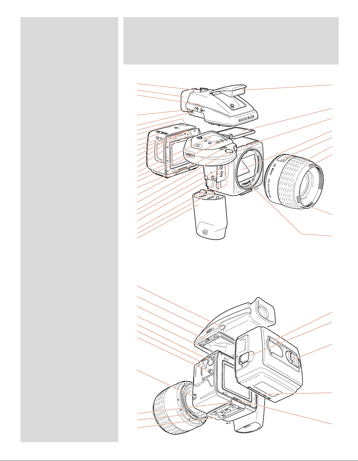
1. Flash unit hot-shoe
H1, hf.eps
020827
2. Rubber eyecup
3. Exposure mode and metering
method selector button
4. Exposure compensation button
5. Eyepiece adjustment dial
6. Magazine LCD
7. Magazine LCD illumination button
8. Magazine control buttons
9. Magazine settings lock
10. AE-L button
11. Film wind-off button
12. User button
13. Rear control wheel
14. Grip LCD
15. Support strap lug
16. Camera control buttons
17. Magazine databus
18. Front control wheel
19. Shutter release button
20. Battery holder button
21. Release cord socket
22. Stop down button
23. Battery holder retaining lever
24. Mirror up button
25. Battery holder
26. Flash unit
27. Viewfinder screen
28. Focus assist light
29. Mirror
30. Distance and depth-of-field scales
31. Focusing ring
32. Lens shade bayonet
33. Filter screw thread
34. Databus connection
35. Viewfinder release button
36. Flash unit catch
37. Viewfinder attachment hook
38. Viewfinder databus connection
39. Magazine release button
40. Flash PC socket
41. Camera strap lug
42. Lens release button
43. Magazine support
44. Databus connection
45. Quick coupling tripod plate
46. Film tab holder
47. Magazine darkslide key
48. Film holder key
49. Magazine support groove
50. Databus connection
Parts & Components
(H2 with film magazine)
1.
2.
3.
4.
5.
6.
7.
8.
9.
10.
11.
12.
13.
14.
15.
16.
17.
18.
19.
20.
21.
22.
23.
24.
25.
35.
36.
37.
38.
39.
40.
41.
42.
43.
44.
45.
26.
27.
28.
29.
30.
31.
32.
33.
34.
46.
47.
48.
49.
50.
8
Page 9

1
Quick Start
– H2 & H2D only
This section is a quick start guide to assembling and
preparing your new camera. From separate items,
the assembly process should take no more than several minutes to complete and when the battery is
charged you will be able to take simple and straightforward photographs immediately.
All the information is repeated later on in the manual, as well as much more in-depth information,
under the relevant sections and headings for easier
search access.
9
Page 10
1
2
H2 / H2D
The following is a simple ‘quick start guide’ to assembling your new H2 or H2D if
necessary, together with a film magazine and a digital back, as appropriate.
3
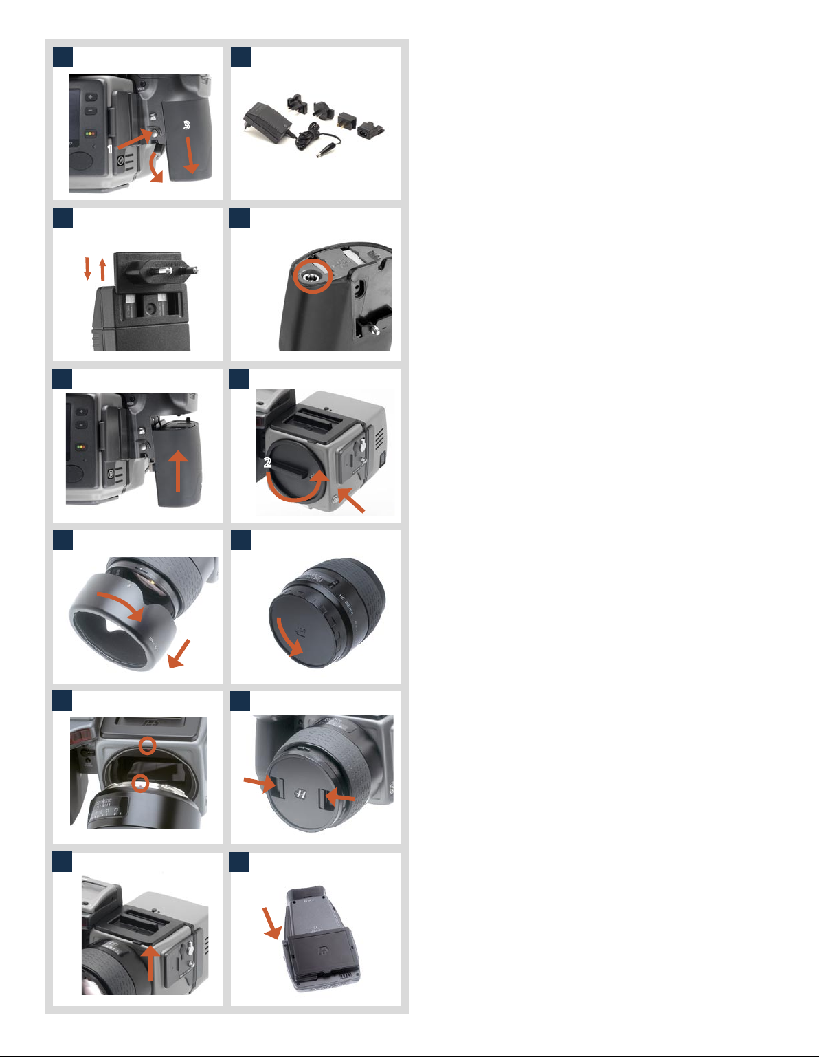
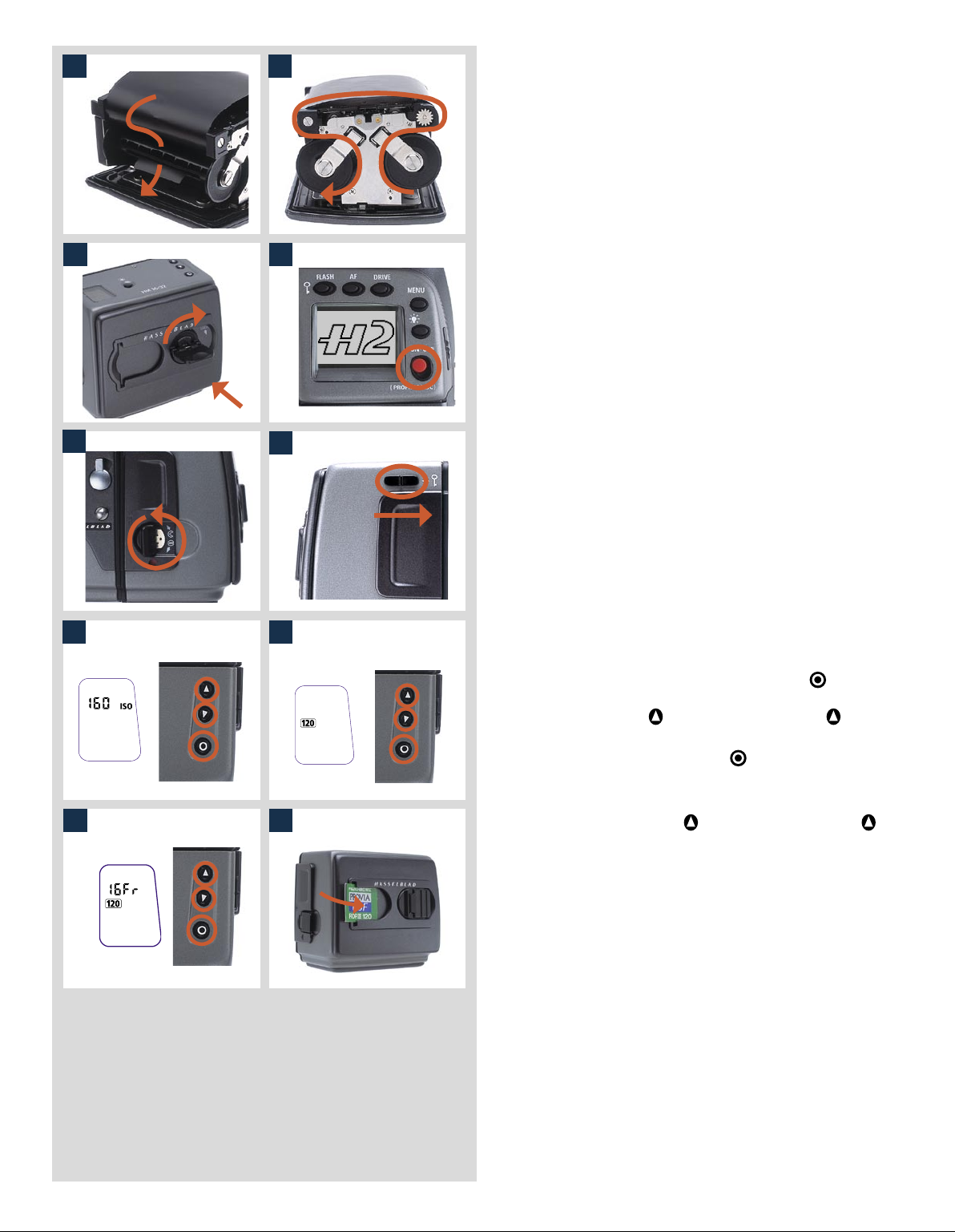
1
1
and simultaneously swinging the battery holder retaining
lever down until it stops. Pull battery downwards.
2. Choose the appropriate plug for the charger.
1. Remove the battery by depressing the battery holder button
2
3
4
3. Attach the chosen plug by sliding it into position, ensuring
that the two electrical contact prongs on the charger cor
rectly enter the two contact sockets on the plug attachment.
-
4. Insert the jack plug from the battery charger into the socket
on the battery. Insert the battery charger into a standard
(100–240V~ /50–60 Hz) domestic socket. Charge the battery
for approx. twelve hours first time, regardless of the red sig
-
nal light (see later section for further details).
5. Holding the battery flat against the camera and aligning the
5
6
two upper lugs with the slot, slide it back into position as far
as it will go. Swing back the battery holder retaining lever
until it clicks back into place.
6. Remove the front protective cover from the camera body by
2
keeping the lens release button depressed and rotating the
cover counter-clockwise until it is released.
7 8
9
11
10
12
1
7. Remove the lens shade by turning it clockwise.
8. Remove the rear lens cap by unscrewing it in a counterclockwise direction.
9. Attach the lens to the camera body by firstly aligning the red
index on the lens mount with the red index on the camera
mount. Grip the lens by the metal barrel (not the rubber
focusing ring) and turn it approximately one quarter turn
clockwise until it clicks into place.
10. Remove the front lens cap by pinching together the two
retaining clips and attach the lens shade to lens by aligning
the indexes and turning the shade clockwise a quarter turn.
11. Remove the top protective cover from the viewfinder screen
location on the camera body by lifting a corner.
12. Remove the protective cover from the viewfinder by depress
ing the viewfinder release button.
10
-
Page 11
13
14
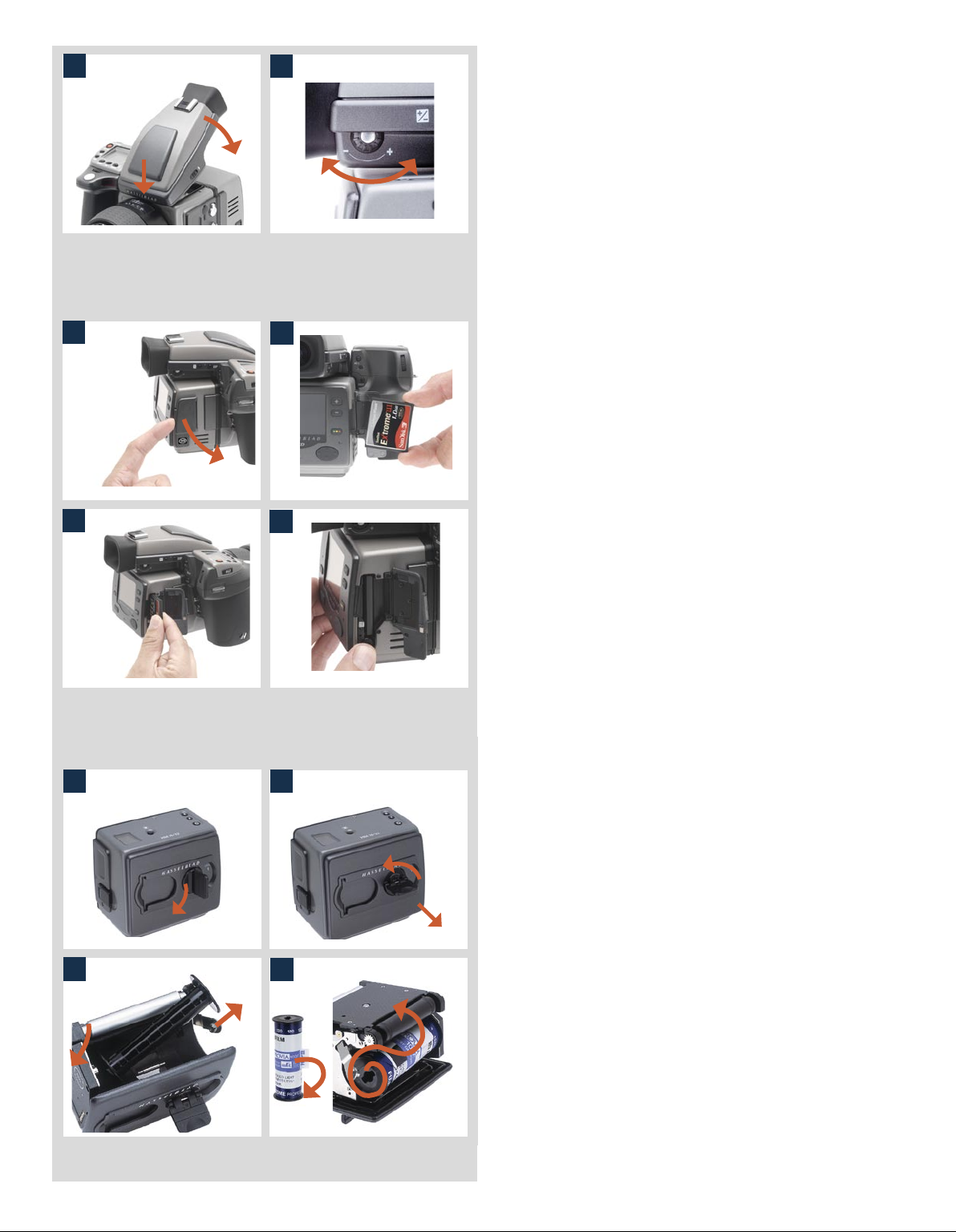
13. While holding the viewfinder at a slight angle, locate the
front section into place on the front edge of the viewfinder
screen recess in the camera body ensuring the central locating lug and databus interface are positioned correctly.
Swing the viewfinder downwards and press firmly until it
clicks into place. Ensure that both sides of the viewfinder are
seated correctly.
14. Point the camera at a smooth toned area. Turn the eyesight
adjustment dial until you achieve optimum sharpness of the
markings on the viewfinder screen.
..........................................................................
Sensor unit with CF card
15
17
19
16
18
20
15. Open the card-holder cover on the sensor unit by insert-
ing your fingernail into the slot at the front of the door and
swinging it open.
16. Hold the compact-flash card so that the connector holes face
into the slot in the sensor unit, with the brand label facing in
the same direction as the sensor unit preview screen.
17. Gently press the card into the slot. If you encounter resist-
ance, it might be because you are holding the card backwards or upside down. Experiment until you find the orientation that allows the card to slide in easily.
18. When the card is able to drop very easily nearly all the way
into the sensor unit, then you are doing it right. Once you
have achieved this, press the card firmly into place until it
sinks another couple of millimeters into the sensor unit and
is held fast. Swing the side panel door shut again.
..........................................................................
Film loading
21
22
19. Fold out the film holder key.
20. Turn the key counter-clockwise 90° and withdraw the film
1
2
holder completely. (Remove the protective slip from the internal battery compartment if necessary)
21. Place an empty take-up spool in the upper spool holder
by pushing one end of the spool against the sprung spool
retaining arm to engage the stud in the spool end. Position
the other end of the spool over the fixed stud in the holder.
Rotate the spool a little if necessary until clicks into position.
22. Completely remove the retaining paper band from a new
roll of film and place it in the lower spool holder in the same
manner as the empty spool. Ensure you do not place the new
film spool the wrong way around! See diagram for correct
orientation.
11
Page 12
2423
insert the tongue of the backing paper into the slot in the
take-up spool.
24. Turn the take-up spool one complete turn to ensure the
tongue is firmly held in place by the overlying paper backing.
Check diagram for correct film travel direction.
23. Pull 8–10 cm (3–4 in) of paper backing from the film roll and
27
2625
azine ensuring the correct orientation. Press firmly inwards
towards the magazine and pay particular attention to see
that both sides are level with the magazine body before
turning the film holder key clockwise 90° to lock the film
holder in place and fold the key back into its stored position.
25. Re-insert the film holder into the main body of the film mag-
2
You might find that increased pressure on the left hand side
of the film holder will more easily ensure a positive and correct positioning in the magazine.
1
28
26. The film will now be wound automatically by the camera
to the first frame position if the camera is in active mode.
Otherwise, activate the camera by holding down the ON/
OFF button for half a second.
27. Fold out the magazine slide key and turn it counter clockwise
360° until it stops. Fold the key back into its storage position.
28. Ensure the magazine setting lock is in the forward (unlocked)
position.
3029
29. If the film has a Barcode, go direct to step 32. If the film has
no Barcode, press the function selector button
on the film
magazine repeatedly until a figure and ISO appears. Press
either the change up
or change down buttons
until
you see the correct ISO rating for the film in use.
30. Press the function selector button
repeatedly again until
you see the film length designation (120 or 220).
3231
31. Press either the change up
or change down buttons
until you see the correct number of frames correct for the
film (8 Fr, 16 Fr or 32 Fr).
32. Insert a tab from a film carton in the holder on the back of
the magazine to remind you which film you have loaded.
..........................................................................
12
Page 13
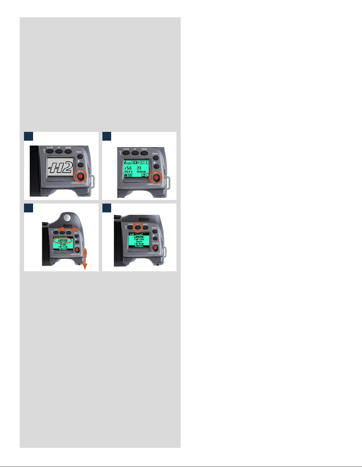
The camera is now complete and ready to use. If you
press the ON.OFF button A for half a second, the camera will activate. If the camera enters STANDBY mode
(the LCD screen on the grip will show the H2/D symbol only), reactivate it by pressing the shutter release
button B halfway (or the ON.OFF button).
You can now explore the menus, buttons, control
wheels, etc observing the changes on the LCD on the
grip as well as the LCD in the viewfinder.
..........................................................................
and finally ...
to ensure the camera is at the standard setting:
3433
3635
33. Click the ON.OFF button.
34. The LCD then displays the Profile screen.
35. Turn either the front or rear control wheel until ‘Standard’ is
highlighted.
36. Press the AF / Load button.
That’s it!
Your Hasselblad camera is now operational in fully automatic mode. In average lighting conditions the camera
will act as a point and shoot camera producing extremely
fine results without the need to touch any other button
than the shutter release!
13
Page 14

2
Function Control
& Display
(H2 / H2D camera body)
■ LCD display on camera
■ LED display on viewfinder
■ Upgradeable firmware
■ Rapidly accessible menu
■ Interactive display
■ Customizable functions
All functions and settings on the H2/D are accessed
and altered by the control buttons and wheels on
and around the grip aided visually by the LCD userinterface.
The information on the grip LCD is in menu format
and has a great deal in common with those found in
modern computers, cell phones, etc. It is pixel based
and therefore has a greater capacity to produce
user-friendly symbols.
14
Page 15
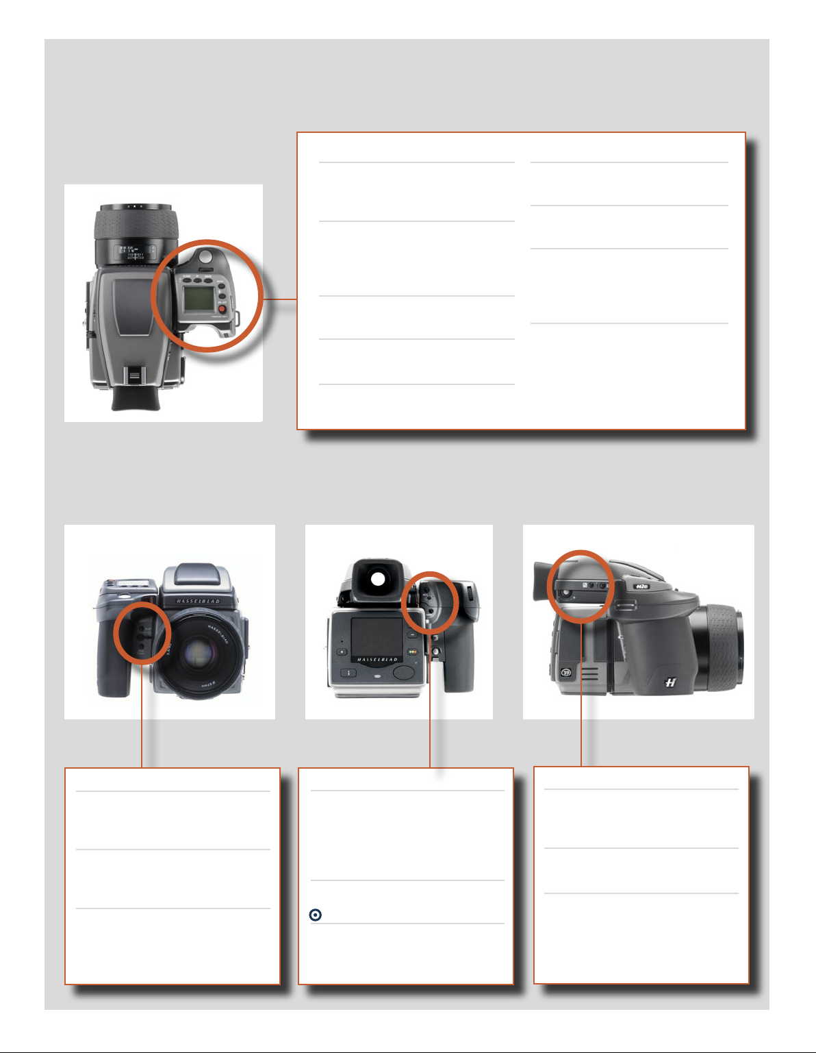
Below is an overview of the primary functions of the control wheels and buttons. Some controls have dual or triple functions according to the state of the menu or setting. A full description can be found further on in this manual.
Shutter release button
Activates camera and releases
shutter.
FLASH / (CONTROL LOCK) button
Lock settings to avoid inadvertent
change. Also accesses flash
settings.
AF button
Accesses focus modes.
DRIVE button
Accesses the various drive modes.
Front control wheel
Accesses and changes various
settings.
MENU button
Accesses menu.
Illumination button
Illuminates grip LCD.
ON.OFF (PROFILES/ESC) button
Turns the camera on and off.
Accesses Profiles and acts as escape
button for other functions.
Rear control wheel
Accesses and changes various
settings.
M.UP button
Raises and lowers mirror. Can be
reassigned to another function.
Remote release cord port
For attaching a remote release cord
(electrical).
STOP DOWN button
Stops down aperture to current
setting. Can be reassigned to another function.
AE-L button
Locks light reading made in both
automatic and manual exposure
modes. Can be reassigned to another function.
USER button
User assignable-function button.
button
No function at present.
15
Eyesight correction adjustment wheel
Personal eyesight adjustment
facility.
EV correction adjustment button
Produces EV compensation.
EXP button
Accesses exposure mode and metering method.
Page 16
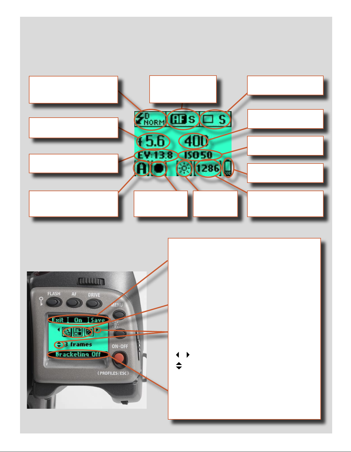
Grip LCD
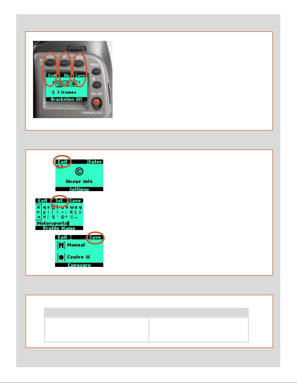
Typical camera grip display. (The information in brackets describes this particular example).
Flash condition indication
(No exposure compensation,
normal flash synchronisation)
Aperture setting
(f/5.6)
Exposure Value display
(EV 9.3)
Exposure mode indication
(Aperture priority setting)
Metering method
indication
(Centre weighted)
Typical camera grip display when changing settings.
Focus setting
(Autofocus setting, single
shot mode)
White balance
(Sunlight)
Command indication
The upper row on the screens describes commands (which
change according to the setting). The button immediately above
each command effects the change. So in this case, for example,
you would press the FLASH button to ‘exit’ from the screen. See
note below.
Drive condition
(Single setting)
Shutter speed setting
(1/400s)
ISO setting
(50 ISO/ASA)
Low battery symbol
‘Exposure counter’
(1286 shots remaining on
chosen storage medium)
Settings symbols
Symbolize the options available when settings are changed. The
active symbol is depicted by a drop shadow.
Control wheel description and direction
Arrowheads symbolize which control wheel should be used to
change the setting they are beside. In this case, the Bracketing
option is chosen by the front control wheel and the number of
exposures in that option is chosen by the rear control wheel.
. . .
= front control wheel
= rear control wheel
Setting information
The lower row on the screen displays information about the current state of the setting. In short, the upper row displays what you
can do, and the lower row displays the current state of settings or
what you have done.
16
Page 17
The basic principle behind making changes is that the appropriate button is first
pressed to access the menu and then settings altered by way of the control wheels.
The appropriate control wheel is designated by arrowheads alongside the setting
description.
Some buttons have a toggle function, the ON.OFF button has a quick
‘click’ action as well as a longer (half-second) ‘press’ action and the shutter
release has two positions: ‘half-press’ and ‘full-press’.
Several buttons on the grip are multifunctional, according to the state of
the menu. In the example illustrated here, the FLASH button functions as
the EXIT button, the AF button functions as the ON button and the DRIVE
button functions as the SAVE button.
At very low temperatures the LCDs require a few seconds to display new
settings.
Examples
The following is a list of the various terms describing the various
actions that appear in the menu (on the grip LCD):
Enter : moves screen down one level on the menu.
Exit : moves screen back up one level on the menu. Does not save any
settings.
Off : deactivates the particular function being set.
On : activates the particular function being set.
Sel. : (Select) - selects the character marked for image info and profile
name
ESC : (Escape) - terminates an action and returns to the main screen.
Does not save any settings.
Save : saves a setting and also moves screen back up one level on the
menu. Can save many changes made in a setting sequence.
Remember the following groupings of ‘saved’ and ‘not-saved’ actions when making settings changes:
SAVED NOT SAVED
‘Quick save’ - half-press shutter release button
Save - press save button (DRIVE button)
Escape - press ESC button (PROFILES /ESC button)
Exit - press exit button (FLASH button)
17
Page 18
Viewfinder LCD
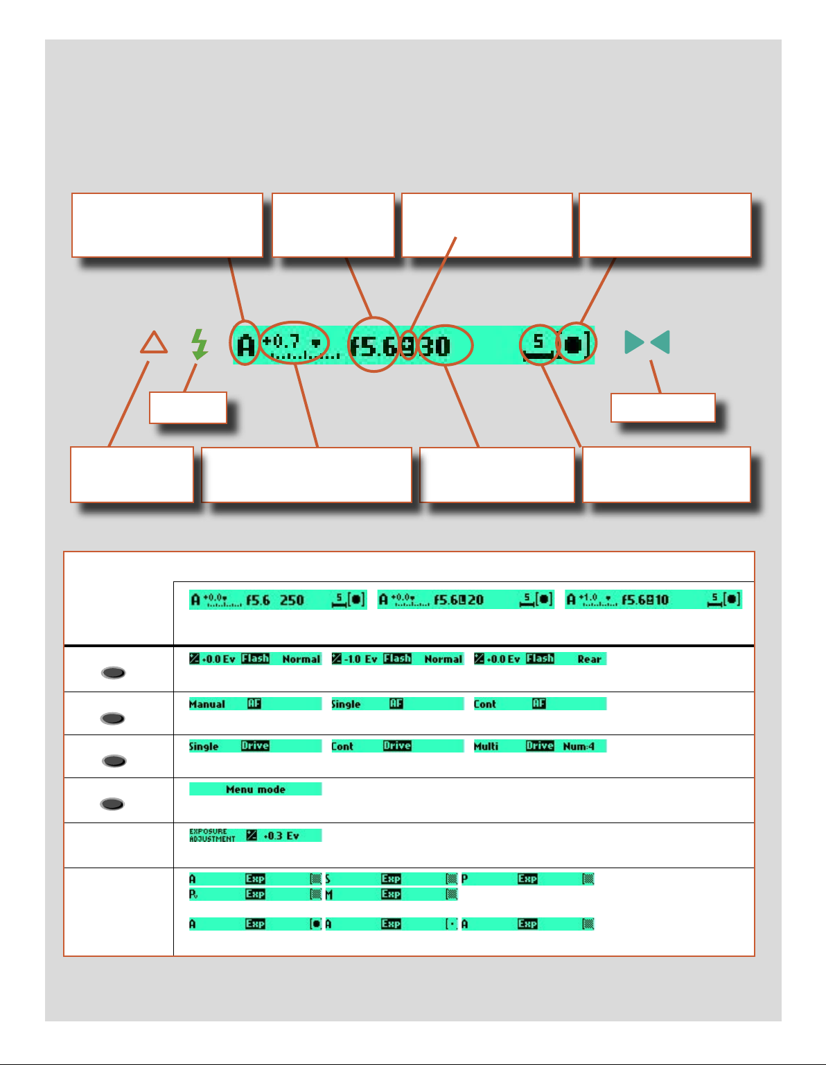
Typical viewfinder display. Note the LEDs will only be visible when activated (by the camera or a setting).
(The information in brackets describes this particular example).
Exposure method indication
(‘aperture priority’ mode)
Flash LED
Warning triangle
LED
Exposure compensation setting
(+0.7 EV)
Aperture setting
(f/5.6)
Exposure compensation
setting reminder symbol
Shutter speed setting
(1/30 second)
Metering method setting
(Centre weighted)
Focus Aid LED
‘Exposure counter’
Some examples of various viewfinder LCD screens visible with standard settings and when specific control buttons are pressed.
Standard settings
FLASH
AF
DRIVE
+/-
EXP
Normal screen Normal screen in AE lock state Normal screen with
�xposure compensation set
Flash mode
AF mode
Drive mode
Menu mode
Exposure compensation mode
Exposure method and metering method
18
Page 19
�
�
Menu charts – general
Throughout this manual you will find charts to explain the steps
and procedures required to alter the various settings. These
charts are laid out to graphically illustrate in a simple manner
how to navigate through the menus. While they include all the
information that would be presented on the LCD relevant to that
section, they cannot illustrate all the possible combinations of
the various symbols seen on a screen at one time as that would
be impractical and too confusing. If you are at all familiar with
cell phone menus, for example, then the design of the layout and
working practice will not be unfamiliar
You should find that, in practice, working your way through a
menu on the camera is a good deal simpler and more obvious
than the written explanation implies!
In the descriptions, various terms are used regarding menu navigation. Menus have ‘trees’, for example, which describes their imaginary graphical layout where you could trace a navigational
path along its ‘branches’. Each new section, or stopping off point
on the branches, seen on the LCD is called a ‘screen’. Therefore a
screen is the graphical display on the LCD of where you are on the
menu and represents the current state of settings.
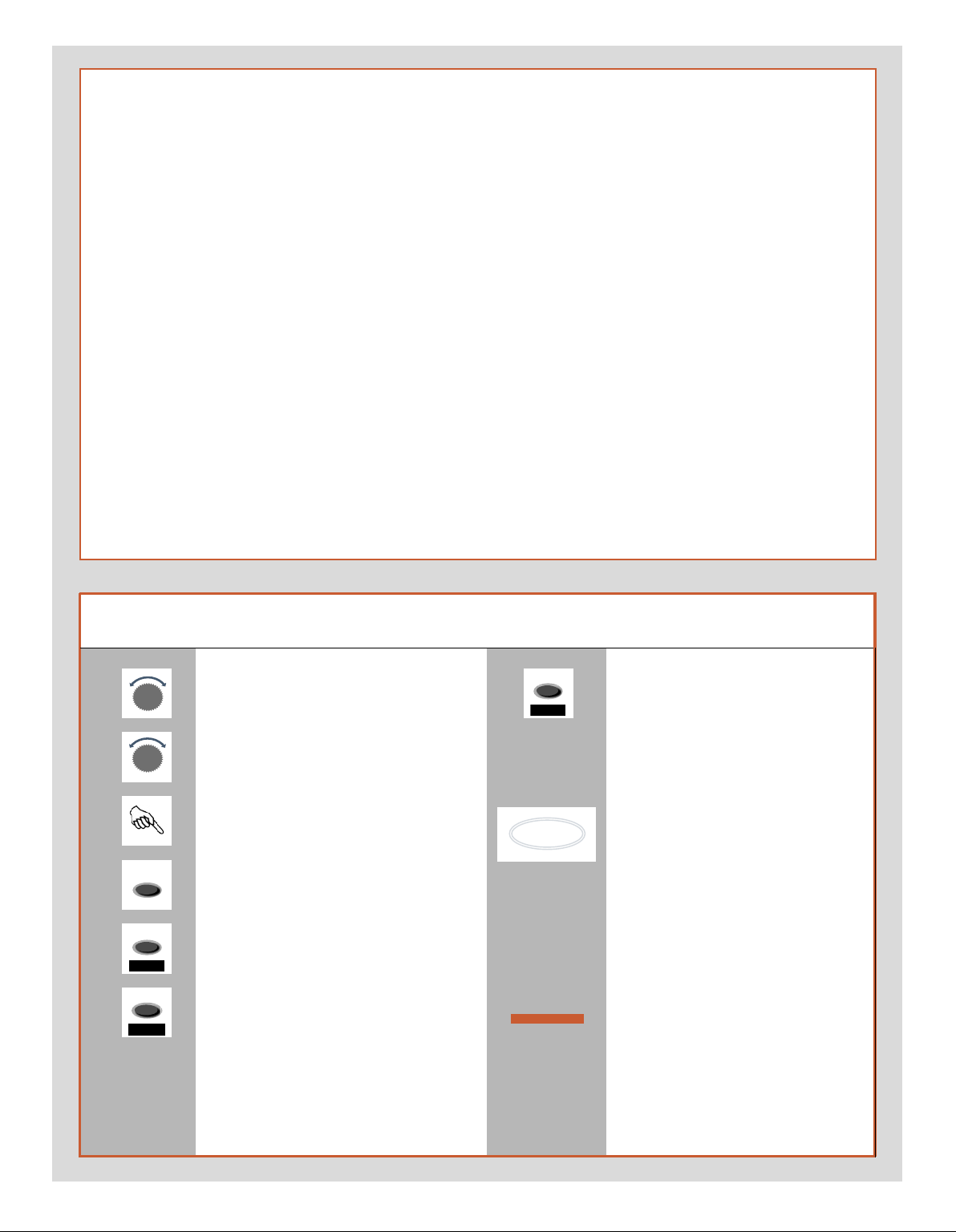
Symbols used in the charts
The H2/D features the advantage of multiple customization of
settings. This means that your personal choice of settings, and
thereby appearance of various combinations of symbols on the
LCD at any time, will not necessarily be the same as many of the
screens illustrated in this manual.
To simplify the descriptions, reference is often made to a ‘main’
or standard screen. Apart from default settings, there is no actual standard setting in the normal sense and therefore you create your own ‘standard’, which of course can be changed at any
time.
The ‘main’ screen is therefore the one you have currently created
and is the one visible on the LCD when photographing (except
where a particular mode is in actual operation, such as self-timer,
for example).
Use front control wheel
(direction depends on user setting)
Use rear control wheel
(direction depends on user setting)
Press button or turn wheel
MENU button on the grip
Choose ENTER
(by pressing DRIVE button on grip)
Choose ON
(by pressing AF button on grip)
Choose Save
(by pressing DRIVE button on grip)
e new setting will be saved and chosen action can be carried out. Setting
will be retained until changed.
Functions in loop on menu
A loop means that the available functions on that particular branch of the
menu can be successively accessed in
either direction of the control wheels
without a break in flow. at is, you
could turn the wheel clockwise or
anticlockwise to arrive at the desired
function.
Main direction of path
through menu
e main path traces step-by-step the
path that has to be taken through the
various branches of the menu tree as
they appear on the LCD to reach the
relevant functions.
19
Page 20
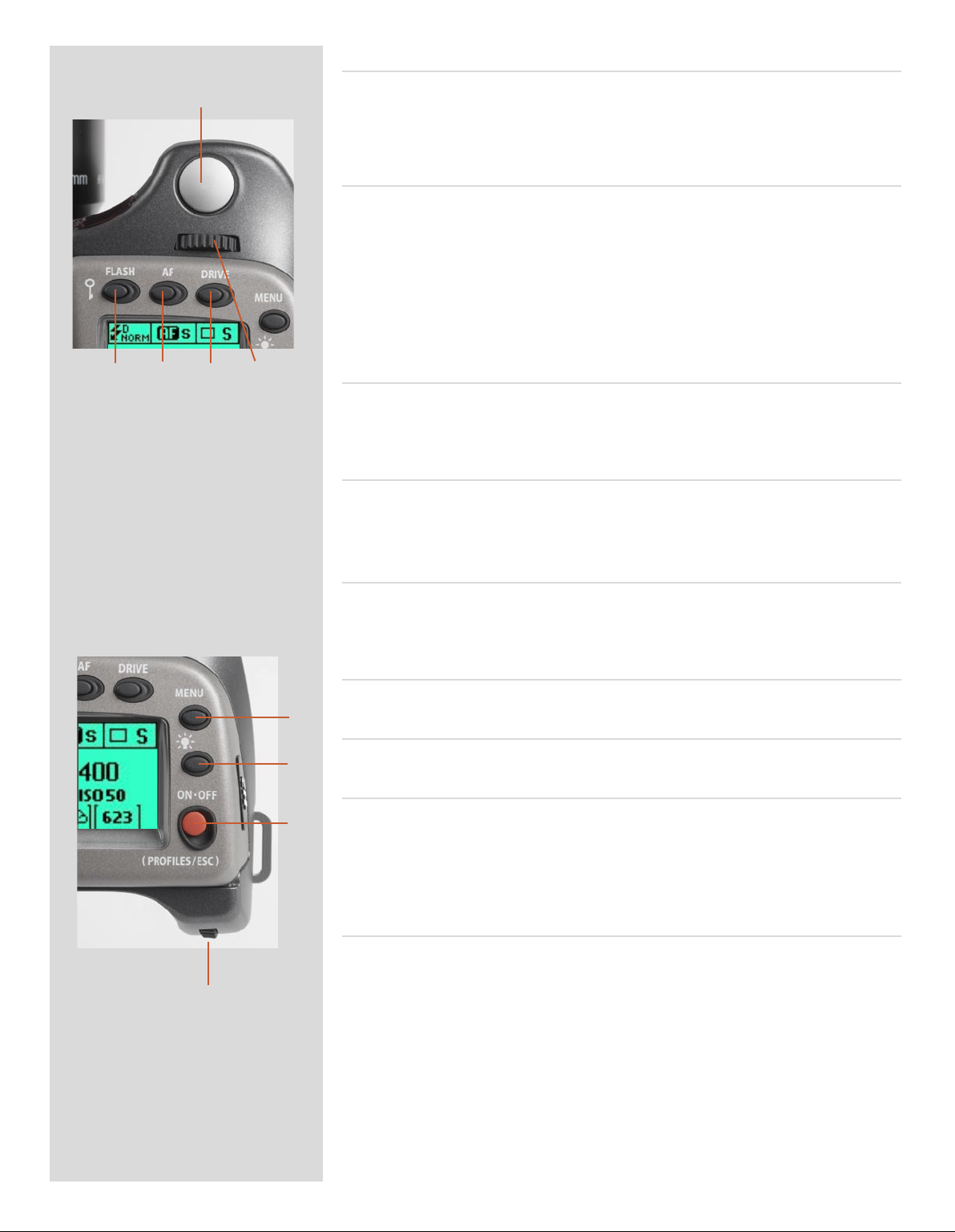
Shutter release button A
A
B C D E
is button has half-press and full-press positions. By pressing half-way (or soly) the
camera, auto focus function and exposure meter can be activated. By pressing all the way
down (or more firmly) the shutter will be released (or the chosen exposure procedure will
begin, as relevant. For example, the self timer is activated with this button)
FLASH / (CONTROL LOCK) button / (EXIT) B
is is a triple function button. If you press the button for one second, the beeper will
sound (if set) and a key symbol will appear on the grip LCD signifying that the controls
(except the shutter release) have been locked and therefore cannot be altered unintentionally in use. Press the button for one second again to unlock (this function can be altered
to lock all controls or control wheels only in ‘Custom options’).
Quickly clicking the button will access the flash settings information on the LCD from
the main screen. See separate section for full details.
is button also acts as the EXIT button for many other settings.
AF button / (ON) / (SEL.) C
is is a triple function button. Press this button to go directly to the autofocus/manual
focus choice screen from the main screen. See separate section for full details. It also acts
as the ON and SEL. (= select) buttons for many other settings.
DRIVE button / (SAVE) / (ENTER) D
is is a triple function button. It will access the drive settings screen on the LCD from
the working screen. See separate section for full details.
It also acts as the SAVE and ENTER buttons for many other settings.
Front control wheel E
e front and rear control wheels are turned to make changes in exposure settings in the
main screen as well as to access the various loop sections of the menu for settings. e
effect of the wheels’ direction is programmable.
MENU button F
Accesses the first level of the menu for settings changes.
F
Illumination button G
Press to illuminate the LCD. Remains active until camera enters standby mode.
G
ON.OFF (PROFILES/ESC) button H
Press the button for a half second to activate the camera. e H2/D start-up logo will ap-
H
pear and then the main screen. Aer a few seconds (customizable) the camera will enter
Standby mode. A press of the button will turn the camera off completely whereas a quick
‘click’ on the button will access the Profiles section of the menu from the main screen.
Note the difference in results between a long press and a quick click of the this button.
Rear control wheel I
e front and rear control wheels are turned to make changes in exposure settings on
the main screen as well as to access the various loop sections of the menu for settings.
I
Acts as quick access exposure compensation control. e effect of the wheels’ direction
is programmable.
20
Page 21
On the rear of the grip, as well as the rear control wheel, there are a further three
control buttons:
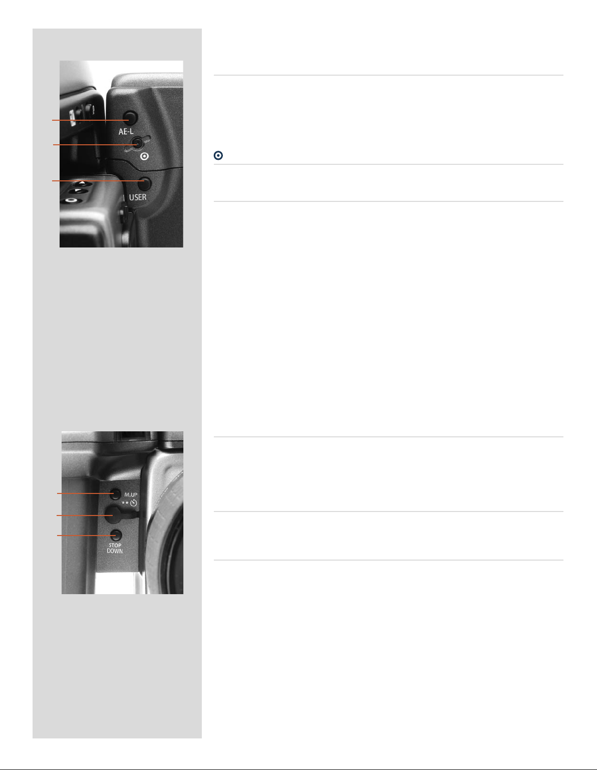
AE-L button J
is button can lock a light reading made in both automatic and manual exposure modes.
It can also be used in Zone mode to take a new reading.
Can be reassigned in Custom Settings to another function.
J
See section on the AE-L button (chapter 8, Light Metering and Exposure Control) for
full details.
K
button K
L
M
N
O
No function at present.
USER button L
is button is purely user programmable to rapidly access a chosen function or screen.
For example, you might use bracketing a great deal and so by one press of this button
you could access the bracketing function without having to navigate through the menu.
e AE-L, Mirror -UP and Stop Down buttons are also user-programmable but are by default
assigned the functions according to their names
The reassignable capability of these buttons is particularly useful and can save you a
great deal of time and effort depending on how you work. You are advised to investigate their potential fully. See under ‘Custom settings’ for full details.
On the front of the grip there are two more control buttons plus the remote cord
release port:
M.UP button M
Press this button to raise the mirror and press again to lower it (toggle function). A quick
double press of the button (two within a half second) will immediately access the ‘Self
timer’ function.
Can be reassigned in Custom Settings to another function.
Remote release cord port N
For attaching a remote release cord (electrical). e Hasselblad accessory jack plug socket
is protected by a captive rubber plug.
STOP DOWN button O
Press this button to make a visual check of the depth-of-field on the viewfinder screen at
the chosen aperture. e aperture will close according to the setting and remain closed
as long as the pressure is maintained. You can alter the aperture at the same time to see
the changes taking place.
Can be reassigned in Custom Settings to another function.
21
Page 22

P Q R
There are also two control buttons on the viewfinder, as well as the eyesight correction adjustment wheel:
Eyesight correction adjustment wheel P
e personal eyesight adjustment facility has a diopter range of -4 – +2.5, to suit most
users.
EV correction adjustment button Q
Press this button to access the EV compensation screen. Settings are made with either
the front or rear control wheels. An EV correction symbol appears on the grip and
viewfinder LCD as confirmation.
EXP button R
e EXP (Exposure) button accesses the exposure mode and metering method options
screen. Settings are made with the front and rear control wheels and the appropriate
symbols appear on the grip and viewfinder LCD accordingly.
22
Page 23

3
Camera Body
■ Aluminium cast in one piece
■ Stainless steel shell
■ Integral Quick coupling plate
■ Digitally controlled
■ Upgradeable software
■ Modular design
■ Integral ergonomic grip
■ Pixel based LCD user interface
The H2/D camera body is a robust construction of cast aluminium
with a stainless steel shell for extreme durability. The workings of
the camera are controlled by silicon technology that provides tremendous opportunities for sophisticated operation. To take just
two examples, the mirror return is slowed down at the last moment by controlling the motor to decrease vibrations and the current usage status of the camera body, lenses etc is recorded and
freely accessible for service intervals, etc.
The integral ergonomic grip houses the main control interface and
also contains the battery holder. An auxiliary shutter in the rear
opening of the camera body protects the sensor unit from exposure
during the various camera procedures. Please take extra care when
handling the camera body without a protective cover or the sensor unit in place to protect the auxiliary shutter. Likewise, the front
opening of the camera body reveals the mirror when unprotected
by a cover or lens. Do not touch or attempt to clean the mirror—
slight marks or dust particles will not affect results. More noticeable problems, however, should be taken care of by a Hasselblad
Authorized Service Center. The camera body also contains the viewfinder screen, which can be easily removed or exchanged without
the use of special tools or adjustment procedures.
23
Page 24
The H2/D camera body is a robust construction of cast aluminium
with a stainless steel shell for extreme durability. The workings of
the camera are controlled by silicon technology that provides tre
mendous opportunities for sophisticated operation. To take just two
examples, the mirror return is slowed down at the last moment by
controlling the motor to decrease vibrations and the current usage
status of the camera body, lenses etc is recorded and freely accessible
for service intervals, etc.
The integral ergonomic grip houses the main control interface and
also contains the battery holder. An auxiliary shutter in the rear open
ing of the camera body protects the sensor unit from exposure during
the various camera procedures. Please take extra care when han
dling the camera body without a protective cover or the sensor unit
in place to protect the auxiliary shutter. Likewise, the front opening
of the camera body reveals the mirror when unprotected by a cover
or lens. Do not touch or attempt to clean the mirror—slight marks
or dust particles will not affect results. More noticeable problems,
however, should be taken care of by a Hasselblad Authorized Service
Center. The camera body also contains the viewfinder screen, which
21
can be easily removed or exchanged without the use of special tools
or adjustment procedures.
Carrying strap 1, 2
e carrying strap is attached by firstly withdrawing the safety
collar. e hook is then freed and attached to the strap lug (fig. 1).
Slide back the safety collar (fig. 2) to ensure the hook remains in
the locked position between the small protruding lugs. e collar
is purposely a tight fit and might need some effort to slide.
3
4
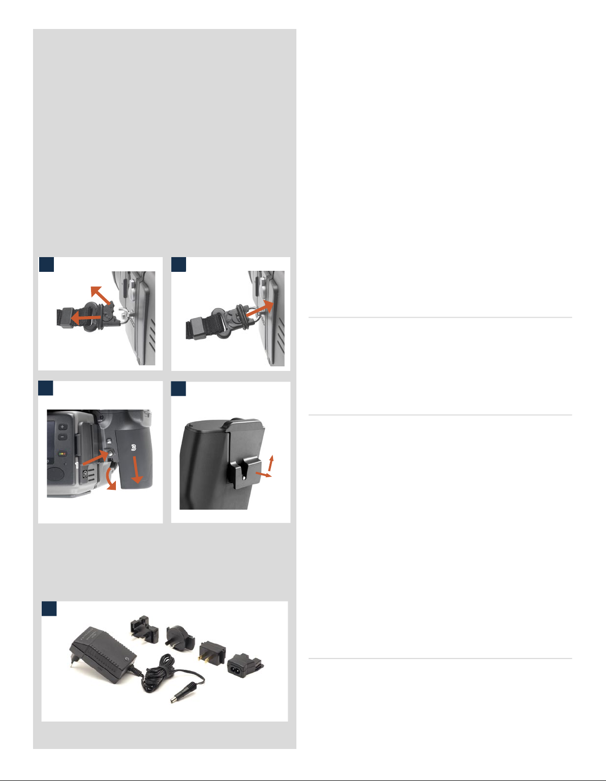
Rechargeable battery grip 3, 4
e H2/D requires battery power for all actions. Being a completely
digital camera there is naturally no mechanical reserve facility. It
3
1
1
2
5
is therefore advisable to keep the reserve grip complete with fresh
lithium batteries handy if you do not use a spare rechargeable grip.
As is the case with most batteries, problems might be encountered
when used in very low temperatures. In this situation it is advisable
to keep the reserve in an inside pocket, for example, to maintain
them near body temperature.
e Battery grip rechargeable 7.2V (3043348) is the standard
power source for the H2/D camera. Remove it from the camera by
depressing the battery holder button and simultaneously swinging
the battery holder retaining lever down until it stops. Pull battery
grip downwards.
If you intend to store the battery grip separately from the camera
you should ensure that the safety cover is in place. It snaps into
place and is removed by pulling outwards and upwards on the
locking clip as in the illustration.
The battery charger 5, 6
e battery charger unit is supplied with five plug attachments to
suit various types of domestic electrical sockets available worldwide.
Other types of socket will require a domestic socket converter.
Attach the chosen plug (fig 6) by sliding it into position, ensuring
that the two electrical contact prongs on the charger correctly
enter the two contact sockets on the plug attachment. Removal is
by the reverse procedure.
24
Page 25
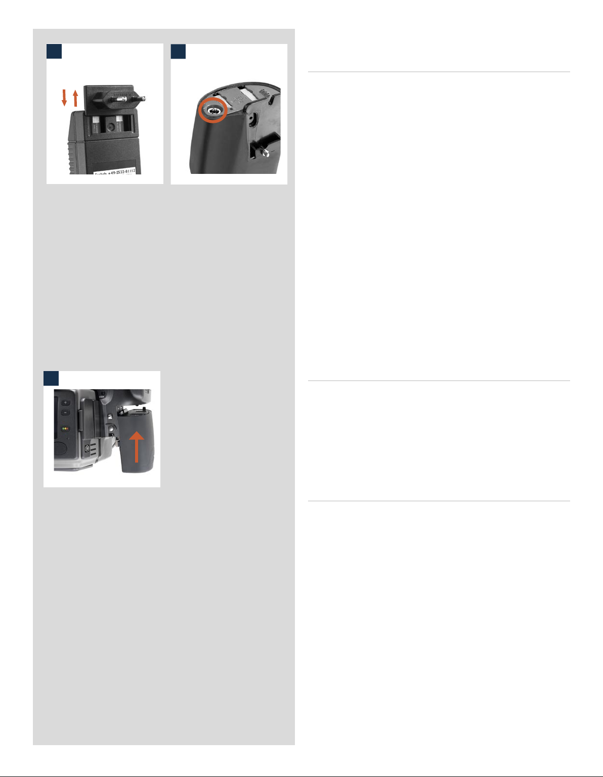
Please note the Battery charger BC-H Li-ion 7.2 VDC (3053568) is
6
7
designed for use with Battery grip rechargeable 7.2V units only.
Charging the battery 7
With the battery grip removed from the camera, insert the jack
plug from the battery charger into the socket (fig. 6) on the battery grip. Insert the battery charger into a standard (100–240V~
/50–60 Hz) domestic socket.
Remember that it will take around 12 hours to load the battery
properly the first time.
e red LED indicator on the battery charger signifies the following:
On (not flashing) = battery is charging
Slow flashing (0.8 Hz) = charging is complete and condition is being
maintained.
Or occasionally
Rapid flashing (3 Hz) = deeply discharged battery is charging
(with reduced current)
Please note that rapid flashing of the LED indicator is not to be
expected. e battery will not normally be so deeply discharged
because the camera will shut down automatically before complete
battery discharge takes place. e indicator might also flash rapidly
for a few moments in some instances when the charger is connected
to the electrical supply. e normal indication is therefore either
‘not flashing’ or ‘slow flashing’.
8
Attaching the battery to the camera 8
Holding the battery holder flat against the grip and aligning the
two upper lugs with the slot in the grip, slide it back into position
as far as it will go. Swing back the battery holder retaining lever
until it clicks back into place.
Please note if you want to use the rechargeable battery with
an H1/H1D model, the firmware in the camera must be version
8.2.2 or later for the battery grip to function properly.
Rechargeable battery grip – general
• The battery should be charged for approximately 12 hours before first time use.
• Maximum battery capacity is reached only after the batter y has been charged
and discharged several times.
• The battery is an environmentally approved Li-ion type and has no ‘memory effect’
of practical importance. This means the battery can be charged before it is fully
discharged without loss of capacity or performance.
• The battery should be charged at an ambient temperature of 10 −30° C.
• When removing a battery from the charger and immediately replacing it with
another, allow a few seconds to elapse so that the charger can automatically reset
for the next charging procedure.
• It is perfectly normal for the battery to become warm when being charged.
• A slight temporary loss of batter y performance might be noticed at very high or
low temperatures. Take the approriate measures if this is the case.
• Long-term storage of batteries with very low charge is not recommended.
• The bat tery has a limited life and its performance is gradually reduced over
time.
• It is advisable to follow the recommendations and precautions in this manual for
product performance and safety reasons.
25
Page 26
Rechargeable battery grip – precautions
e following precautions should be adhered to:
Battery grip rechargeable 7.2 V:
• Connec t the battery grip to the camera correctly.
• Keep the protective cover in place when not in use. (Short-circuiting across keys
in a pocket, for example, could cause a fire risk).
• Do not use the battery grip for anything other than an H1/H1D/H2/H2D camera.
• Do not immerse the battery grip in liquids.
• Do not incinerate the battery grip. Please recycle or discard in an environmentally
approved manner.
• Do not use any other charger than the Hasselblad battery charger BC-H Li-ion 7.2
VDC (3053568).
Battery charger BC-H Li-ion 7.2 VDC:
• Read the instructions before using the charger.
• Use indoors only (protect against moisture).
• Do not use charger for anything else than charging of Battery grip rechargeable
7.2 V (3043348).
• Do not short-circuit the jack plug.
• Do n ot alter the c har ger in any w ay other tha n changi ng the p lug
attachment.
10
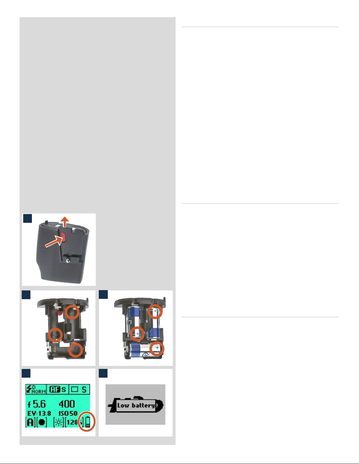
Reserve lithium battery grip 9, 10, 11
e reserve lithium battery grip is attached and removed in the
9
11
same manner as the rechargeable grip.
Press the red battery cassette retaining button inwards on the
holder to release the battery cassette (fig 9). Load three CR-123
lithium (or equivalent) into the cassette, ensuring the polarity of
each battery is correctly oriented (see the ‘+’ markings on the batteries and the cassette) (fig 10, 11). Re-insert the cassette into the
battery holder, ensuring that it is seated properly in place and that
the red button returns fully into the locked position. Holding the
battery holder flat against the grip and aligning the two upper lugs
with the slot in the grip, slide it back into position as far as it will
go. Swing back the battery holder retaining lever as far as it will
go into the locked position.
Battery life 12, 13
Battery life is dependent on a number of variable factors and
therefore cannot be exactly predicted.If the camera is le in the
active state instead of standby for long periods, for example, then
battery life will be reduced. A low-battery state is indicated as a
symbol on the grip LCD (fig. 12).
When the batteries are almost completely exhausted, a warning
message ‘Low battery’ will appear on the grip LCD (fig. 13). e
1312
camera will not function at all when this message appears and
battery change is essential.
When the low-battery icon appears, the camera automatically
enters a temporary power-saving mode. This is recognizable by
a slower pace for all the actions in an exposure sequence. The
camera actions also sound differently .
This mode is designed so that you can continue working for a
while, even though the batteries are too low for working in the
normal manner. Naturally, you should change the battery pack
as soon as possible to restore normal action again.
26
Page 27
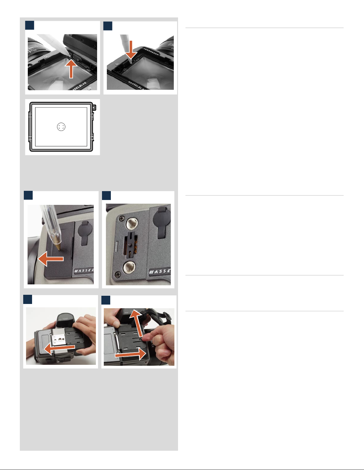
14
Viewfinder screen showing composition frame marking.
15
Viewfinder screen 14, 15, 16
e H2/D is fitted with a Spherical Acute-Matte D viewfinder
screen for extreme brightness, clarity and even illumination. An
optional accessory screen with a grid pattern is also available.
To change a viewfinder screen, remove the viewfinder to access
the viewfinder screen. To remove the screen, place the tip of a
ballpoint pen or similar in the viewfinder screen removal lug and
pull upwards. To replace the screen, position the right side of the
screen in place so that it sits correctly in the recess. Place the tip
of a ballpoint pen or similar in the viewfinder screen replacement
indentation and press downwards until the screen snaps into
position. Try to avoid touching either surface of the screen with
bare fingers.
Do not attempt to clean the screen by immersing it in water, or
use any kind of cleaning fluid. If the screen becomes damp, do
not use hot air to dry it. Use a soft cloth on the upper surface only.
Seek advice from an Authorized Hasselblad Service Center if the
screen becomes particularly soiled. Remember that particles or
greasy marks on the screen might impair the viewfinder image
but have no effect whatsoever on the recorded image.
16
18
17
19
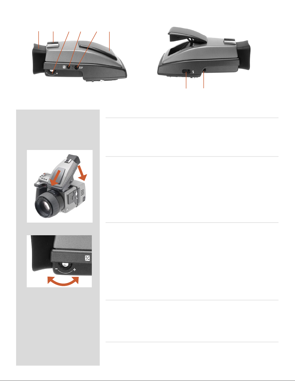
Accessory connection 16, 17
On the le hand side of the camera body are two accessory retaining
screw threads (M5), as well as a databus connector, protected be
neath a cover. e screw threads are a future-safe design feature for
new products while the connector is for service purposes only.
e cover can be removed by inserting a pointed object, such as
a pen, in the small hole and then sliding it to the le, as in the il
lustration. e retaining clip can then also be removed to access
the connector.
PC-connector
A PC connector for non TTL-flash synchronisation is located on
the le side of the body. It is protected by a captive rubber plug.
Protective base plate 18, 19
To attach the protective base plate, slip it over the camera foot
until it stops. To remove it, li the securing catch while pushing
the plate back as in the illustration.
-
-
27
Page 28

4
Viewfinder
■ Multi-mode light metering
■ Full exposure information
■ 100% image
■ 90° viewing angle for eye-line composition
■ Full image for spectacle wearers
■ Integral dioptre adjustment
■ Integral flash unit
The 90° viewfinder provides a laterally corrected 100% image at
eye-line level. It features a wide-range diopter adjustment to suit
most users. The viewing distance is designed to provide full frame
view even for eyeglass wearers. The bright Spherical Acute-Matte
D focusing screens (located in the camera body) are interchangeable to suit preference, each of them naturally indicating the spot
light metering area for accuracy in exposure estimation. The information display located beneath the viewing frame is continually updated and visible and is back lit for optimum visibility. This
LCD also duplicates much information visible on the grip LCD for
immediate checking. In addition to the LCD, there are four LEDs
providing general warnings, flash and focus information.
The viewfinder also features a pop-up fill-flash unit for added convenience.
The viewfinder requires no batteries as it is supplied with power
from the camera body and can be easily and quickly removed.
Please see section on ‘Flash’ for full details.
See the ‘Camera Body ‘ section for details about the viewfinder
screen.
The exposure compensation button and exposure mode button
are described in the ‘Function Control‘ section.
28
Page 29
A B C D E F
Parts & Components
A. Rubber eye cup E. Exposure method / mode button
B. Hot shoe F. Integral flash unit
C. Eyesight adjustment wheel G. Flash unit button
D. Exposure compensation button H. Viewfinder release button
Attaching and removing the viewfinder
G H
1
2
While holding the viewfinder at a slight angle and resting it on the top of the camera,
slide the viewfinder forward until the front locating pin is in position in the recess in the
front edge of the viewfinder screen aperture on camera body. Press the rear part of the
viewfinder firmly downwards until it clicks into place.
Ensure that both sides of the viewfinder are seated correctly and that it has been firmly
attached. Failure to do so could cause an intermittent malfunction if the databus interface
connections between the viewfinder and camera body are not positively secured.
To remove, grasp the viewfinder in the right hand and while depressing the viewfinder
release button, li the rear of the viewfinder up and away from the camera body.
Eyepiece adjustment
No corrective lenses are needed to adjust the eyepiece to suit most requirements. e
diopter range is from -4 D to +2.5 D. Eyeglass wearers can rapidly and accurately change
the settings according to whether they wish to wear eyeglasses for viewing or not.
Personal eyepiece adjustments can be carried out by pointing the camera at the sky or
similar smoothly toned area. While holding the camera in your le hand, you can with
your right thumb turn the adjustment wheel until the markings on the viewfinder screen
reach the optimum sharpness for your eyesight.
If you normally wear eyeglasses for distance viewing and intend to wear them for camera
use then do not remove them for the above procedure. If, on the other hand, you prefer
to remove your eyeglasses for camera work, then repeat the above procedure without
wearing your eyeglasses.
Rubber eye cup
Two rubber eye cups are available for the H2/D. e one supplied is suitable for users
who do not intend to use eyeglasses when photographing. e second shorter eye cup is
for those who either prefer to position their eye further from the viewfinder and those
who wish to wear eyeglasses.
e eye cups can be rapidly changed by a Hasselblad Authorized Service Center.
Integral flash unit
See section on ‘Flash’ for full details.
29
Page 30

5
Lenses
■ Rapid and accurate automatic focusing capability
■ Central electronic shutter
■ Instant manual focus override with natural friction
■ Instant automatic-focus return capability
■ Non-rotation of filter or accessory when focusing
■ Non-rotation of lens barrel in automatic focusing mode
■ Shutter speeds 32 sec to 1/800 sec with flash sync
■ Reversed lens shade serves as protection
■ Automatic detection of extension rings and converters
All HC lenses have been specially formulated for the H system
to produce the extremely high performance expected from
Hasselblad to meet the demands from conventional and digital
photography alike. In addition to extreme sharpness, the design
also incorporates a soft, pleasant looking boké (the visual quality of the out-of-focus areas of the image). All lenses feature an
electronically controlled central shutter designed to extremely
fine tolerances for supreme accuracy that also provides flash synchronization with all speeds from 32s to 1/800 s. All lenses have a
very rapid automatic focus capability with instant manual override. To ensure reliable and fast autofocus in low contrast and low
light conditions, a focusing-assist light (on the grip) is automatically activated. Aperture and shutter control is set via the control
wheels on the camera grip.
As a general rule, lens shades should always be fitted to achieve
optimum performance. Protective filters (UV / Sky) should also be
considered at least when working outdoors in harsh conditions.
(See Accessories section for information about the CF Adapter that
allows the use of C type lenses from the Hasselblad V-system).
30
Page 31

21
Parts and components 1
A
B
C
D
E
3
2
1
4
A. Lens shade index
B. Manual focus ring
C. Focusing distance scales
D. Depth-of-field scales
E. Lens index
Attaching a lens 2, 3
Remove the front protective cover on the camera body by depressing
the lens release button and keeping it depressed while turning the
cover counter-clockwise. Remove the rear lens cap by unscrewing
it in a counter-clockwise direction. Align the index on the lens
with the index on the camera body and rotate the lens clockwise
(bayonet fitting) until it clicks into place.
Removing a lens
Depress the lens release button and keep it depressed while rotat
ing the lens counter-clockwise until it stops and li it out. Replace
protective caps on the lens immediately and on the camera body
if necessary.
If you try to rotate the lens before you press the lens release button,
it might lock. In this case, rotate the lens clockwise a little first
5
6
and then re-attempt removal with the correct procedure: button
first, then lens.
-
Front lens cap 4
Front lens caps are released for removal and attachment by insert
ing a thumb and index finger into the recesses and pinching in the
direction of the arrows.
Filters
Filters have a screw thread fitting (67 / 77 / 95 mm, according to
lens) and are screwed clockwise into place. As there is no rotation
of the front section of the lens when focus is changed, filters do not
rotate either. is is particularly useful when using polarizing or
graduated filters where the orientation is normally critical.
Lens shades 5, 6
All lenses are supplied with lens shades that additionally pro
vide extra protection for transport and storage when mounted
in reverse. Lens shades have a bayonet fitting and are turned
clockwise into place aer ensuring the index on the lens shade
aligns with the index on the front of the lens. When mounted in
reverse, they are attached by matching the indexes and turning
counter-clockwise.
Shutter and aperture control
-
-
Both the shutter and aperture are electronically controlled and are
adjusted by the control wheels on the grip. ere are no separate
manual setting rings on the lenses or camera body.
e chosen settings are displayed both on the grip LCD and in
the viewfinder LCD. See the ‘Exposure Control’ chapter for a
complete explanation.
31
Page 32

Depth-of-field calculation 7
7
ere are two distance scales (in feet and metres) visible through
the focus distance window on the upper part of the lens barrel.
ere is also a central lens index mark and a depth-of-field scale.
e focusing distance is read off the chosen scale from the central
lens index.
Depth-of-field can be calculated as follows:
1. Focus the lens as required.
2. Make an exposure reading (auto or manual) and note the
aperture setting.
3. Find the markings on either side of the central index that correspond to the chosen aperture.
8
4. From these two markings, read off on the required lens distance scale the two corresponding distances.
5. The depth-of-field (at that particular aperture and focus setting) will be the area included between these two distances.
In the example given here, the focusing distance is set at nearly 3
metres. At an aperture of f/22, the depth-of-field would therefore
extend from just over 2 m to approximately 4.5 m.
Stop down / depth-of-field 8
A visual depth-of-field preview can be made by depressing the STOP
DOWN button while viewing the image on the viewfinder screen.
10
11
12
9
Infrared focus settings 9
As infrared rays form an image at a different plane to that formed
by visible light, the normal focus settings do not apply. Proceed as
follows in manual focus mode:
1. Focus the lens in the conventional manner until satisfied.
2. Note the distance setting against the central lens index.
3. Re-align this distance setting against the infrared mark
(coloured red) instead of the central lens index.
Alternatively if you have already calculated the required distance,
you can make a manual distance setting by using the distance
Lens focus setting too far
beyond the distance of the
subject framed by the central
section in the viewfinder
scales together with the infrared mark instead of the central lens
index.
Focus aid 10, 11, 12
As well as the conventional view on the focusing screen to ensure
a sharp image, the H2/D also features LED focus aid appearing
as two arrowheads to the right of the viewfinder display (except
Focus setting too close for
the distance of the subject
framed by the central section
in the viewfinder
Focus setting correct
for lenses with a maximum aperture of f/6.7 or smaller). e arrowheads provide confirmation of a precision focus setting and
are a useful aid when making a setting with eyesight alone.
Manual focus setting
When the le arrowhead alone appears it means the focus setting
is too far beyond the chosen distance (the area framed within the
central zone in the viewfinder) and when the right arrowhead
alone appears it means the focus setting is too close. Focus is correct when both arrowheads appear together. If the focus cannot
be established, then both arrowheads flash.
32
Page 33

Automatic focus setting
Focus is correct when both arrowheads are visible together. Focus
is incorrect if only one arrowhead is visible. If the focus cannot be
established, then both arrowheads flash.
CF Adapter
e CF adapter is an optional accessory that allows virtually all
C type lenses from the V-system to be used on H-system camera
bodies. is automatically expands the potential lens range for H
cameras by more than a dozen different focal lengths. e automatic focusing system in the H camera can be used as a guide for
manual focus setting. Light is measured at full aperture with all
lenses which produces aperture and shutter speed information
display in the camera for manual setting. With CFE lenses, however, a preset aperture is automatically transferred to the camera.
Shutter cocking is manual with all lenses and is swily carried
out by an easily accessible lever.
33
Page 34

6
Film Magazine
■ Automatic 120/220 compatibility
■ Automatic wind on / wind off
■ Automatic film advance
■ LCD information panel
■ Integral darkslide
■ Customizable data imprinting
■ Illuminated LCD
■ Barcode recognition
■ Count-up or count-down film frame reminder choice
The film magazine is a sophisticated semi-independent unit
within the modular system. It has its own power supply for individual information storage, LCD panel, illumination, etc.
Much information is transmitted and received between the
magazine and the camera body, so ensure the databus connection is kept clean and not damaged in any way. It is advisable to fit the magazine protective cover when storing a film
magazine to protect both the databus connection and the
darkslide.
34
Page 35

A B
F G H I J K L
C
D
E
Parts and components
A. LCD panel G. Darkslide key
B. LCD illumination button H. Darkslide indicator
C. Change up button I. Film tab holder
D. Change down button J. Film holder key
E. Function selector K. Magazine settings lock
F. Film plane index L. Databus interface
LCD panel A
A
B
e various functions are accessed by repeatedly pressing the
function selector button (loop menu) and changes made by the
‘change-up’ and ‘change-down’ buttons. Any settings are automati
cally saved. At very low temperatures the LCD will require a few
seconds to display new settings.
-
LCD illumination button B
e LCD can be illuminated by pressing the display illumination
button, which is accessible when the magazine is not attached to
the camera. e LCD will remain illuminated all the time you keep
C
E
D
F
the button depressed, up to a maximum of 10 seconds. Aer 10
seconds has expired, you must release the pressure on the button
and press again to obtain a further 10 second period of illumination. Remember that using the illumination function very oen
will noticeably shorten the life of the battery in the magazine.
When the magazine is attached to the camera, the button on the
magazine is inaccessible but you can still illuminate the LCD by
pressing the illumination button on the grip instead.
Change up button
Can alter the settings ‘upwards’. For example, to increase the film
speed setting. Toggle action.
Change down button
C
D
Can alter the settings ‘downwards’. For example, to decrease the
film speed setting. Toggle action.
Function selector E
Selects the four functions that can be changed on the magazine. e
functions are on a menu loop so that repeated pressing of the selec
tor button will successively access all functions in turn. Aer
35
-
Page 36

K L
a time-out of five seconds of non-activity, the display returns to
HG
the main screen.
Changes can only be made when the settings lock switch is in
the unlocked position.
Film plane index F
Provides a measuring point for the actual position of the film plane
in the magazine. Used for calculations in critical applications.
Darkslide key G
Withdraws and replaces the darkslide. Fold out the key and turn it
JI
counter-clockwise 360° (towards the open symbol) to withdraw it
and clockwise 360° (towards the closed symbol) to replace it.
The darkslide can only be withdrawn when the magazine is
attached to the camera.
Darkslide indicator H
Indicates whether the darkslide is in place or withdrawn:
RED = stop ! = exposure CANNOT be made
(magazine can be removed from camera)
WHITE = ok ! = exposure CAN be made
(magazine cannot be removed from camera)
If you attempt to make an exposure when the darkslide is closed,
however, you will receive a warning message in the viewfinder
and grip LCDs – ‘e darkslide is closed’.
Film tab holder I
Holds an ID tab from the film roll pack as a reminder of the type
of film loaded. Don’t forget to change it if you change film type!
Film holder key J
Secures the film holder in the magazine. Fold out the key and
turn counter-clockwise 90° to remove the film holder and turn
clockwise 90˚ to lock the film holder in place.
Magazine settings lock K
All settings can be locked to avoid inadvertent changes. To change
the settings, slide the settings lock (see illus) to the right until it
stops. Aer the changes have been made, slide the settings lock
to the le (see symbol on magazine) again to secure the new settings.
Databus interface L
Data interface between magazine and camera. Ensure the contacts
are kept clean and protected from damage. Keep the protective
cover on when the magazine is being stored or transported.
36
Page 37

Operation
Battery
1
e magazine uses a battery to retain information and settings when unattached from the
camera. When attached to the camera body, the magazine takes its power requirements
from the camera batteries. e magazine battery will normally be effective for 1-2 years
depending on use (off camera illumination, for example).
When the battery is in a very low condition, (approx... 1 month of use le), a low-battery
symbol appears on the magazine LCD as a warning.
e magazine will continue to function with no battery power le as long as it remains
attached to the camera body. However, when detached, the settings will not be stored.
Battery replacement 1, 2
Release the film holder by folding out the film holder key and rotating it 90° in a counterclockwise direction. Withdraw the film holder completely. On the bottom plate on the
2
inside of the film magazine housing you will find a slotted circular battery cover. Insert
a small coin or similar into the slot and rotate the cover about 20° in a counter-clockwise
direction. e cover will be freed and the battery can be removed. Replace with a fresh
CR2032 / 3V lithium (or equivalent) battery. Observe the polarity and ensure the positive
(+) face is uppermost and replace the cover (ensure the retaining lugs are inserted in the
battery compartment slots), locking it into place by rotating it in a clockwise direction
until it stops. If you inadvertently insert the battery incorrectly, the film magazine will
not be damaged though it will not function. Try to avoid touching the surface of the
battery with your bare fingers as sweat residue can decrease the electrical conductivity
of the battery casing and might cause corrosion.
Aer battery replacement, the magazine’s parameters return to the default settings
(Barcode, 120, Data-on, Count up).
Attaching and removing the magazine 3, 4
3
4
1
You cannot remove a magazine from the camera body if the magazine darkslide is not in
place, (when the magazine darkslide indicator on the magazine shows white). Neither can
you withdraw the magazine darkslide when the magazine is not attached to the camera.
Both these restrictions therefore prevent accidental film loss caused by fogging.
Attachment
Position the magazine retention groove onto the magazine support on the camera body
ensuring that they are correctly positioned. Swing the magazine towards the camera
body and firmly press into place with a click. If there is resistance, the magazine retain
ing catch on the camera has probably been inadvertently released. In that case, push the
release button again to reset the catch.
You can attach and remove the magazine with or without the film holder in place. If you
just want to change to a new film, you can remove and reload the film holder without
having to remove the whole magazine.
Removal
Ensure that the darkslide indicator on the magazine shows red (signifying that the
darkslide is closed). Firstly push the lever of the magazine release button to the right (fig.
4/1) and while maintaining that position press the centre of the button firmly inwards
towards the camera body (fig. 4/2) to finally release the magazine.
-
Ensure you press on the centre of the button, not on the lever.
2
You cannot remove a magazine if the darkslide is not closed.
If the film holder is inadvertently removed mid-film, then exposed frames will natu
rally be lost due to light fogging. However, if the film holder is re-inserted, the film will
automatically be advanced by three frames to position fresh unexposed film. The film
counter will also correspondingly add on three frames to the original number recorded
before the film holder was removed.
37
-
Page 38

Magazine settings
A
B
1 2
3
C
Press the function selector (
access:
A. Film speed (ISO / Bar Code)
B. Film length (120/220/ Number of frames)
C. Data (on/off )
D. Frame counter (count down / count up)
E. Low-battery warning symbol
button ) repeatedly to successively
D
E
Film speed setting / Barcode
e film speed (ISO / ASA) can be set automatically or manually.
Automatic setting uses a Barcode (only some films have this feature,
notably Fujifilm). is is the default setting.
Film settings (ISO / film length) are automatic only if the maga-
zine is set at Barcode automatic. That is, a barcoded film cannot
override a manual film speed setting but a manual setting can
override the film speed of a barcoded film.
Films without a barcode must have their speed set manually.
A manual setting must also be made if you want to override
the speed setting of a barcoded film.
To access Manual setting:
1) Ensure the magazine settings lock is in the unlocked position.
4
4
EXAMPLE
2) Press the
together with ISO.
3) Press either the
ting.
4) The new setting will be saved automatically after a time out of
five seconds.
5) Return the LCD settings lock to the locked position.
button until a figure (or barcode symbol) appears
or the
button to reach the required set-
If you use both standard and barcoded films (or overridden
barcoded films), check that you have changed the settings
5
accordingly.
Film length/number of frames
Both 120 and 220 films can be used. 120 film will produce 8 (for
use with ‘half-length’ 120 films only) or 16 frames and 220 film
will produce 32 frames.
If the film has a barcode, then film length setting (and film speed
setting) is automatic. e LCD will automatically show the barcode
symbol and the appropriate film length. (Note that film speed can
be overridden with barcoded films, but not film length).
If, however, the film has no barcode then proceed as follows:
To access film type setting:
Film speed
Film length
Data
Frame counter
1) Ensure the magazine settings lock is in the unlocked position.
2) Press the
3) Press either the
setting.
4) The new setting will be saved automatically after timeout.
5) Return the magazine settings lock to the locked position.
button until the 120 or 220 symbol appears.
or the
button to change the desired
38
Page 39

Manual film speed setting.
Data imprinting setting.
220 film length setting.
‘Frames remaining ’
counter setting.
Data imprint setting
Data imprinting can be activated or deactivated through the magazine menu.
To access data setting:
1) Ensure the magazine settings lock is in the unlocked position.
2) Press the
3) Press either the
button until the Data symbol appears.
or the
button to reach On or Off.
4) The new setting will be saved automatically after a time out of
five seconds.
5) Return the magazine settings lock to the locked position.
Operation and changes made to the data imprinting function
are accessed through the camera menu. Please see separate
section for full details.
Frame counter setting
e frame counter can be set to show either how many unexposed
frames remain on a film or how many frames have already been
exposed. e LCD shows your choice of setting by adding the
word Remain as a reminder of the number of frames remaining or
‘countdown’. Absence of this word implies the opposite, namely,
‘count-up’, so it denotes the number of the next frame to be used
(for example, the figure 4 means three frames have already been
exposed). is information is also automatically displayed on the
grip LCD and viewfinder LCD though only as a figure above a
symbol.
To access frame counter setting:
1) Ensure the magazine settings lock is in the unlocked position.
2) Press the
3) Press either the
setting (toggle function).
• ‘on’ will show the number of frames remaining on the roll.
• ‘oFF’ will show the number of the next frame in the series.
4) The new setting will be saved automatically after a time out of
five seconds.
5) Return the magazine settings lock to the locked position.
button until Remain appears.
button or the
button to reach the desired
Low-battery symbol
e low-battery symbol only appears on the magazine LCD when
the battery needs changing.
Example
In the example shown here:
• 120 film length set manually
• the film speed (ISO160) has been set manually
• 5 frames have already been exposed (therefore with regular
120 film, 11 frames remain)
• the battery is functional
39
Page 40

Film loading
e film magazine can be loaded either on or off the camera.
Regularly check the interior of the magazine and remove dust,
particles or any scraps of paper from previous rolls of film. Load
1
2
1
2
4
3
5
1
and unload film magazines away from direct light sources.
1) Fold out the film holder key and turn it counter-clockwise 90°.
Withdraw the film holder completely.
2) Place an empty take-up spool in the upper spool holder by
placing one end over the fixed stud in the holder and the other
end underneath the sprung spool retaining arm. Rotate the
spool a little if necessary until it clicks into position.
3) Completely remove the retaining paper band from a new roll
of film and place it in the lower spool holder. See diagram for
correct orientation. Ensure you do not place the film spool the
wrong way around!
4) Pull 8–10 cm (3–4 in.) of paper backing from the film roll and
insert the tongue of the backing paper into the slot in the
take-up spool. Turn the spool one complete turn to ensure the
tongue is firmly held in place by the overlying paper backing.
5) Re-insert the film holder into the main body of the film magazine ensuring the correct orientation. Press firmly inwards
towards the magazine and pay particular attention to see
that both sides are level with the magazine body before turning the film holder key clockwise 90˚ to lock the film holder in
place and fold the key back into its stored position. You might
find that increased pressure on the left hand side of the film
holder will more easily ensure a positive and correct positioning in the magazine.
If the camera is active or in standby mode the film will be
wound automatically by the camera to position the first frame
(this function can be changed in ‘Custom options’ so that
the film is advanced only when the shutter release button is
pressed the first time).
Beeper
e beeper sounds immediately aer the last-but-one frame has been
exposed. is function can be turned off in Custom Options.
Film wind on and off 6, 7
Wind on: See ‘Film wind-on’ under Custom Options for a setting
2
6
7
choice.
Wind off: When the last frame has been exposed, the film will
automatically be wound off. However, to wind off a film sooner,
press the film wind off button (fig. 6). Use a ballpoint pen or similar
to activate it. You must also confirm the message on the grip LCD
(fig. 7) before the film winds off.
Unloading a film
To remove a film, remove the film holder in the same manner
as when loading a film. Grip the exposed roll of film firmly and
remove. Ensure the paper backing is wound tightly and that it is
sealed with the band properly (the band may need to be moistened
to activate the adhesive depending on type). Store exposed films
away from strong light sources and contact with sharp objects.
Move the remaining empty spool to the take-up spool compartment.
40
Page 41

7
General overview of
H2D sensor unit &
CFH digital back
■ 3 operating and storage modes
■ Direct shooting to 3FR
■ FlexColor worklow efficiency
■ Instant Approval Architecture
H system cameras were designed with digital photography
in mind right from the outset so the H2D and CFH are natural
developments within the world famous H system.
Seamless integration and consequently increased efficiency
and improved workflow are the results of such a design that
features shared information visible on the LCDs/ OLED as well
as a shared battery, for example.
FlexColor, the image processing software that is included
with an H2D or CFH, can take advantage of the information
that is stored with each capture both for future reference and
for enhanced processing to fine-tune optical characteristics,
for example.
FlexColor also provides for tethered use allowing digital capture control directly from the computer.
HC lenses were also formulated to meet the very high demands made by digital sensors, which they do with ease.
41
Page 42

In very simple terms, a digital back holds a light sensitive sensor in place at the film
plane. The electronic signals from the sensor are then processed and stored as a
digital file.
As an electronic colour image is made up of three components − red, green and
blue which combine to form a so-called RGB image − the sensor’s task is to convert
a multi spectrum light image into three digital files (red, green and blue) for combination later on.
The H2D and CFH use a CCD (Charged Couple Device) type sensor that has millions
of light sensitive areas on its surface each of which creates a pixel.
Each pixel in the sensor is filtered to create the three separate red, green and blue
files. Software then processes these electronic files as a package into a Hasselblad
3FR file which in turn is processed in FlexColor to produce Hasselblad 3F files or various other formats such as RAW, TIFF, JPEG etc.
The three components of the image file are later recombined on the computer
screen to produce the familiar full colour image.
•
The captured image can be temporarily stored internally with a CF card, on a
Hasselblad Imagebank or the hard disk on a computer via FlexColor. When using
the camera tethered in a studio you can control all the digital aspects of camera
operation from a computer using FlexColor. See the separate FlexColor manual for
further details.
As the H2D and CFH are purely electronic devices, attention to power supply is vital.
When working untethered it is therefore important to plan either battery loading or
battery replacement to ensure continued workflow.
Likewise, image storage is limited, particularly when using flash cards and appropriate steps should also be taken when planning a shoot.
External storage is accomplished by FireWire connection to a separate hard disk or
a computer.
•
When attaching and removing the back, pay particular attention to the image sensor area. The sensor itself is covered and therefore protected by the glass IR filter but
take great care when handling. If you need to clean the filter, see later section for
specific details. When storing separated from the camera, always ensure you have
replaced the protective cover.
If you scratch or mark the filter in any way, it will show up on every shot.
Replacements are expensive so treat the glass surface with at least as much care as
you would a lens.
The sensor itself is not accessible for any kind of cleaning or maintenance by a user.
Do not attempt any such action as you will almost certainly damage it irreparably.
As is the case with all electronic devices pay extra care when working in damp environments and avoid damp conditions for storage.
42
Page 43

A
F
B
C
D
E
K L M N O P Q R S
G
H
I
J
Parts, components & control panel buttons
The control panel with its bright OLED screen is the main graphical interface for image checking and sensor unit setting changes when not connected
to a computer. However, the grip LCD is still the interface for focus and exposure settings.
The buttons are used for browsing images and navigating the menu system. Two of the buttons, located at the bottom-right and -left of the screen, are
given an on-screen label that changes according to the current context (e.g., the bottom-right button sets the approval rating when browsing images,
but confirms settings when using the menus).
OLED screen A
Displays preview images and the menu system even in bright light
and from acute angles.
Microphone B
Function currently not used.
MENU / (EXIT) button C
Opens and closes the menu system. Also used for various other
tasks (EXIT button, for example) as you issue commands within
the menu system indicated by a label beside the button on the
preview screen.
View-mode button D
Steps through the various view modes for the preview
image: standard, histogram overlay, image details, screen
off and full-screen.
Busy-light (back) E
Flashes green to indicate that the digital back is performing an
operation (such as saving a new capture) and is not available for
new commands.
Zoom-in button / SELECTION (+ button) F
Zoom-in button (to make the view larger) for the preview
image. Also acts as a selection button when viewing
43
Page 44

available image batches, media (e.g., compact-flash, ImageBank,
and value setting on the menu.
Zoom-out button / SELECTION (– button) G
Zoom-out button (to make the view smaller) for the
preview image. You can continue to zoom out to view
several small images at once and finally to view and select batches
and media. Also acts as a selection button for value setting on
the menu.
Approve / (OK) button H
is button steps through the three approval levels,
thereby assigning an approval status to the image currently displayed (or selected) in the preview screen. (part of the
Instant Approval Architecture system). Also acts as a confirmation button (OK button) for some types of menu operations, such
as deleting images; indicated by a label beside the button on the
preview screen.
Busy-light (card) I
Flashes red to indicate that a file is being loaded onto a card.
Navigation button J
A four-way rocker button enabling you to step through preview
images and navigate the menu system. To use it, press the side of
the button that corresponds to what you wish to do (e.g., move
up, le, right or down).
Safety catch N
Used when removing the digital back / sensor unit.
CCD and IR filter O
is is the light-sensitive element, which is positioned behind a
permanently mounted IR filter. Usually, this assembly will either
be inside the camera or protected by the cover. Always be very
careful not to touch or scratch the surface of the filter when it is
exposed and to replace the plastic cover whenever the digital back
is not mounted on a camera.
WARNING: never attempt to remove the glass filter—you will
probably ruin the CCD if you do so.
See Cleaning the CCD section for cleaning.
Mounting plate P
is plate, which has a slot just behind it, fits onto the magazine
retaining hook on the back.
Flash sync input (CFH only) Q
Flash synch connector (protected behind a rubber cover) for use
with a view camera. Not required when an H2 is used.
Flash sync output (CFH only) R
Flash synch connector (protected behind a rubber cover) for use
with a view camera. Not required when an H2 is used.
Flash-card slot K
Flash-card removal button L
Flash-card slot cover M
General
Using the menu on the H2D/CFH is very similar to using a menu on a cell phone or similar. When you
enter the menu (by pressing the MENU / button) you will be see an initial list:
ISO
White Bal.
Media
Browse
Storage
Settings
The first four items are immediately accessible for changes, indicated by the appearance of a plus
and minus sign in the highlight frame meaning the settings can be altered by the Zoom in / Zoom
out buttons. Storage and Settings are more detailed and therefore require further navigation.
It is advisable to quickly skim through this section of the manual initially to see build up a picture of
the menu structure with its various sections
FireWire connector S
Insert a FireWire 800 cable here to connect the digital back to a
computer or Image Bank CF.
On the following pages you will see an illustration of the thinking behind the menu, its structure and
how changes in settings are made and stored.
Some of the buttons have a double function while others remain single function. For example, the
navigation button always leads you through the menu in the direction that the arrowhead illustrates. The Zoom in/out buttons ( and ) though, for example, act as image enlargers and
reducers as well as confirmation buttons, according to where you are on the menu.
44
Page 45

Simple introductory overview of menu access, navigation and settings choice.
The menu is structured in a manner similar to cell phones
and similar electronic devices.
Various branches within the tree system are accessed by
pressing the navigation button until you reach the point
where a choice has to be made.
The OK (Approve) button or SELECTION (Zoom-in/Zoomout) buttons are then used to confirm choice.
After pressing the MENU button, the main menu list appears.
The blue frame highlights where you are on the menu. Press
on the ‘up’ and ‘down’ symbols on the navigation button to
move up and down the list.
You can return to the standard image view by pressing either on the ‘left’ symbol on the navigation button or on the
EXIT/MENU button again.
The need to continue further into the menu is indicated by
the arrow symbol beside the menu item.
Press the ‘right’ arrow symbol on the navigation button to
access the next part of the menu.
When you reach the final destination of your choice (this
might take several moves), PLUS and MINUS symbols appear to the right in the frame round the item.
You then press the Zoom-in /Zoom-out /SELECTION buttons to access a loop list of choices.
In the example on the left, 50 is the ISO value shown. By
pressing either button the alternatives appear – 100, 200,
400 and then back to 50 again – both on the list as well as
on the upper low to the left (in the case of ISO value).
Pressing the EXIT/MENU button will then confirm the new
setting.
In the next example on the left, the name of a new batch is
changed by pressing a combination of the Zoom-in /Zoomout /SELECTION buttons as well as the navigation button.
You can then confirm your choice with the OK (Approve)
button or revert to the previous status by pressing the EXIT/
MENU button.
See later sections for more comprehensive information.
45
Page 46

By using the buttons on the control panel you
can navigate down through the various levels
in the menu. It provides the source of information about image files and also provides a
way of making custom settings so the digital
back suit s your way of working.
Below is a simple overview of what is available and where it is situated on the menu.
Overview
of menu
structure
MENU
STORAGE
ISO
Sets the light sensitivity of
the sensor. Equivalent to
‘film speed’.
MEDIA
Determines where files
will be stored (flash card,
Imagebank).
DELETE
For single or multiple deletion of images.
BATCH
Used to create new storage
folders (batches) and name
them.
WHITE
BALANCE
Set to match the colour temperature of light used.
BROWSE
Sets the approval status
(classification) filter for easier
and quicker image browsing.
FORMAT
Used to format compact
flash cards and Imagebanks
for optimum use.
DEFAULT
APP LEVEL
Assigns a default approval
status (classification) to all
new images.
COPY
Used for off-loading images
from a flash card to an
Imagebank.
SETTINGS
USER INTERFACE
Sets menu language, power
down, sound, date & time
and several other custom
settings.
MISCELLANEOUS
Sets the way the camera/
digital back appears to a
computer. Also displays
firmware version.
46
CAMERA
Sets which type of camera
body is being used with the
digital back.
DEFAULT
Resets all custom settings
back to the original factory
settings.
Page 47

Don’t forget the menu shortcuts!
To help you work faster, the digital back provides shortcuts to some of the most commonly used menu commands that do not
otherwise have a dedicated button on the front panel.
These are accessible by pressing and holding one of the front-panel buttons for a second or so. These are mentioned where appropriate elsewhere in this manual, but we summarize them here for your convenience.
Try to memorize these quick actions to save time and effort later!
To delete images
To toggle the overexposure indicator
To set the browse filter
Press and hold until your preferred
filter is indicated.
See ‘Using Instant Approval
Architecture’ for full details.
Press and holduntil the display
begins to flash (or stops flashing) its
overexposed areas.
See ‘Overexposure Indicator’ for full
details.
Select the target image and then
press and holduntil the delete dia-
log opens.
See ‘MAIN MENU > Delete’ for full
details.
47
Page 48

8
CFH setup
Setup overview
Although the CFH is primarily designed for use with a Hasselblad H2 camera, it can also
be used with a Hasselblad H1 camera or with nearly any camera that has been fitted with
an adapter for mounting Hasselblad film magazines. However, not all CFH features are
available with camera bodies other than the H2.
Although most of the information in this manual assumes that you are using an H2
camera, this section explains how to use the CFH with other types of camera bodies and
describes how each solution differs from using an H2.
Using with a Hasselblad H2
Attaching to a Hasselblad H2
1. Remove the CCD/filter cover from the CFH by placing your thumb on the upper
recess and pulling the top of the cover away from the CFH. Push downwards on the
cover to release the lower catch on the cover from the mounting-support plate of the
CFH.
CAUTION
Be very careful not to touch or scratch the CCD/filter surface while it is exposed. Keep
the cover in a convenient place as you must always replace it when you remove and/or
store the CFH.
2. Rest the mounting plate of the CFH on the magazine-support hook on the camera
body, ensuring that they are correctly positioned. The end of the support shelf is
angled up at 90 degrees—this fits into the slot behind the mounting plate.
3. Swing the CFH towards the camera body and firmly press into place until you hear
a click. If there is resistance, then the retention mechanism of the camera may have
been reset. To fix this, rotate and depress the release button on the camera body (see
H2 user manual for details).
4. Before you can start shooting, you must have some storage media available. Do one
of the following:
• Insert a compact-flash card. See ‘Using compact flash memory cards’ for details.
• Connect an ImageBank. See ‘Working with an ImageBank’ for details.
48
Page 49

• Connect a FireWire hard disk. See ‘Working with a Standard FireWire Hard Disk’ for details.
1
• Connect to a computer. See ‘Working Connected to a Computer’ for details.
Powering the CFH on an H2
When connected to an H2 camera body, the CFH takes its power from the H2 battery
pack. e combination is turned on and off using the on/off switch on the camera body.
Please see the H2 user manual for details about the on/off switch, standby times etc.
Removing the CFH from an H2
2
3
1. Disconnect all cables (if any) from the CFH, including all FireWire and flash-trigger
cables.
2. Remove the viewfinder assembly from the camera body by pressing its release but
ton and lifting it up and away from the body. See also the H2 user manual for details
about removing and replacing the viewfinder assembly.
3. While pushing the safety catch backwards on the digital back (3 illus. A) push the
lever of the digital back release button to the right (3 illus. B) and while maintaining
that position press the centre of the button firmly inwards towards the camera body
(3 illus. C) to finally release the magazine.
4. Tilt the CFH away from the camera body and pull it away.
-
Caution:
The CCD and filter are now exposed; be very careful not to touch or scratch the exposed
A
surface.
5. Replace the CCD/filter cover by hooking the bottom edge of the cover behind the
mounting plate of the CFH and then pressing the top of the cover against the back
until it clicks into place.
B
C
Using with a Hasselblad H1
Using with a Hasselblad H1 Camera
e H1 was Hasselblad’s first camera specifically designed for both digital and film-based
photography. e CFH and H2 are the next generation in this line. e CFH can be fitted
on an H1 camera, but the integration is less complete than with an H2 camera.
Mounting onto an H1
Mount the CFH to your H1 camera just as you would mount a film magazine. If you have
trouble, please see above section Attaching to a Hasselblad H2
for help.
Configuring for use with an H1
e CFH comes pre-configured for use with an H1 or H2 camera; both require the same
camera-body setting (“H1”), which prepares the CFH to work with either of these two
camera bodies. However, if you have been using the CFH with another type of camera
(e.g., a view camera), then set the MAIN MENU > SETTINGS > CAMERA > Body
to “H1”. See MAIN MENU > SETTINGS > Camera
e CFH remembers your setting, even when turned off. However, you must adjust this
setting as required each time you move the CFH to a new type of camera.
for details.
Limitations when using an H1
When you use the CFH with an H1, the following limitations apply when compared with
the standard H2 operation described elsewhere in this manual:
and your H1 manual
entry
49
Page 50

• You must always work connected to a computer and shoot using FlexColor. This is necessary in order to power the CFH. You must furthermore use a computer that supplies
power through its FireWire port; not all computers do this (especially laptops).
• Camera settings details are not communicated to the CFH, so these are not stored
with each shot as they are with the H2.
Using with other cameras (flash-sync mode)
When set to work in flash-sync mode, the CFH communicates with the camera only via
the flash-sync cable. When a flash signal travels along the cable, the CFH is trggered to
make a capture. If you are also using a flash system, the CFH forwards the signal to your
flash system at the same time.
To use the CFH with a non-Hasselblad camera in flash-sync mode, your camera must
be fitted with an adapter that enables Hasselblad film magazines to be attached to it.
ese adapters are available from several third-party manufacturers. e camera-back
mounting fixtures are identical to those of a Hasselblad film magazine, so no additional
adapters are required.
Usually, you will use this feature with some type of view camera, such as a Sinar or other
technical camera.
This functionality is not fully supported. Several technical issues, such as specialized
shutter behaviour and the method by which your camera sends flash signals along the
cable, can result in a non-functioning solution. Future firmware updates for the CFH
may expand the number of third-party cameras supported by the flash-sync feature.
Attaching the CFH
1. Attach your Hasselblad film magazine adapter to your camera, following the
instructions given in the adapter user manual.
2. Carefully remove the CCD/filter cover and keep it in a place where you can find it
again. You must always replace it when you remove and/or store the CFH.
CAUTION: be very careful not to touch or scratch the CCD/filter surface while it is
exposed.
3. Attach the CFH directly to your adapter exactly as you would a film magazine.
4. Connect the flash-sync cord from the flash-sync output of your view camera to
the flash-sync input of the CFH. You must do this even if you are not using a flash
because the CFH relies on the flash signal in order to trigger a capture.
5. If you are using a flash system, then connect a flash-sync cord from the flash-sync
output of the CFH to the input of your flash system.
6. Connect the CFH to your computer using a FireWire cable.
Powering the CFH
When you are using a camera other than an H2, the CFH must get its power via a
FireWire cable connected to your computer. You must therefore always work in studio
mode using FlexColor when you shoot with a view camera. You must furthermore use
a computer that supplies power through its FireWire port; not all computers do this
(especially laptops).
Configuring for flash sync mode ( View / large format cameras only ! )
e CFH comes pre-configured for use with an H2 camera. If you want to use it in flashsync mode, set the MAIN MENU > SETTINGS > CAMERA > Body entry to Flash Sync.
Depending on your camera model, you may also need to use the Shutter Delay and/or
Exposure Time settings in order to get the solution to work correctly. See MAIN MENU
> SETTINGS > Camera for details about these settings.
e CFH remembers your setting, even when turned off. However, you must adjust this
setting as required each time you move the CFH to a new type of camera.
50
Page 51

Making exposure settings and taking shots
Cameras other than the H2 are not able to communicate with the CFH. You must therefore make exposure settings as follows when you use a view camera:
1. Select an ISO rating for the CFH using the FlexColor software.
2. Take light-meter readings and set aperture and shutter speed as would be appropriate for exposing film of your selected ISO rating.
3. Using FlexColor, set the camera-back exposure time to be just slightly longer than
the value to found for the camera body.
4. Press the shutter release on your camera body to take the picture. This will trigger
the CFH, computer and (if connected) flash system via the attached cables.
51
Page 52

9
Initial General
Settings and
Preparation
Language
If you have not already done so, you may wish to change to your
chosen language now. You can choose between:
ENGLISH
GERMAN
1
2
FRENCH
ITALIAN
SPANISH
JAPANESE
CHINESE
Setting the menu language
Proceed as follows:
3
5
4
6
1. Press the MENU/EXIT ( ) button to open the menu.
2. Press the NAVIGATOR button ( and ) to select the
SETTINGS sub-menu.
3. Press the NAVIGATOR button () to open the SETTINGS
menu.
4. Press the NAVIGATOR button () to select the USER
INTERFACE sub-menu.
5. Press either ZOOM button ( or ) to choose a new language (in this case, Spanish).
6. Press the MENU/EXIT ( ) button again to close the menu.
52
Page 53

Storage & Shooting
Image storage modes / shooting
e H2D / CFH can store captured images in three ways:
1. Untethered / Compact flash card mode
In this mode the H2D/CFH acts independently of other connections. Images are stored
on the internal, removable compact-flash card.
• The main advantage with this mode is the freedom of cables and extra equipment.
• The main disadvantages with this mode in the field are the battery power capacity and the
size of the card’s holding capacity.
Please note that the recommended types of CF cards are Sandisk Extreme-III or Lexar
Professional 133x. Other cards will work but offer a reduced capture rate.
2. Semi-tethered / Imagebank mode
is mode enables you to attach the camera to a portable Hasselblad Imagebank via a
FireWire cable. e Imagebank features massive storage capacity and high-speed data
transfer. It is small, lightweight, battery powered and easily clips to your belt, so the
solution is just as portable as the untethered option.
• The main advantage with this mode is the great number of images that can be stored
without a pause.
• The main disadvantage with this mode is the extra equipment and cablage needed that
might restrict mobility in some cases.
3. Tethered / Studio mode
is mode enables you to connect your H2D/CFH directly to a computer and to operate the system using Hasselblad FlexColor soware and store images on a computer
hard-disk.
• The main advantages with this mode are the almost limitless storage capacity and being
able to work on the images (with Hasselblad FlexColor) on a large screen.
• The main disadvantage with this mode is the lack of mobility to any great extent.
Selecting the current medium
A choice has to be made concerning where the captured images will initially be stored.
e current storage medium is the location to which new shots are saved and from which
you can browse using the navigation button. In many cases, the destination medium is
selected automatically, for example:
• When you are connected to a computer, then images are always saved directly to the
computer hard disk.
• When only one medium is connected (e.g., a compact-flash card), then this medium is
automatically selected.
However, if you are working away from your computer and have several media attached
(e.g., both a card and an Imagebank, then you may need to select a medium explicitly if
you want to browse its contents and store images new to it.
ere are two ways of selecting the current storage medium:
53
Page 54

• See “Selecting the Current Storage Medium” for details.
• Use the zoom-out button to zoom all the way up to the top level,
which shows all connected media, and then zoom in on the appropriate medium and batch.
See “Navigating Media and Batches” for more information about
selecting media and batches in this way.
3. Tethered / Studio mode
is mode enables you to connect your camera directly to a
computer and to operate the system using Hasselblad FlexColor
soware and store images on a computer hard-disk.
• The main advantages with this mode are the almost limitless storage
capacity and being able to work on the images (with Hasselblad
FlexColor) on a large screen.
• The main disadvantage with this mode is the lack of mobility to
any great extent.
Using compact flash memory cards
When shooting to a compact-flash card, the H2D/CFH is completely
self-contained. No additional wires or connectors need to be attached.
e H2D/CFH is shipped with a 1GB (or larger) compact-flash
card, which is able to hold over 20 shots. Lossless compression is
applied to the images, so the actual size of each capture can vary,
thereby affecting the total number of shots you can fit on the card.
You can purchase additional, possibly larger-capacity, cards and
change them as each card becomes full.
1
3 4
5
Note that the camera can copy the contents of its compact flash
card to an Imagebank – even when no computer is attached. This
2
A
B
enables you to backup your shots and then clear space on the card
to keep on shooting. See section on “Transferring Images”.
Inserting a card
1. Open the CF card slot cover on the sensor unit.
2. Behind the cover, you can see a slot for the card (A), possibly
with a card already inside, and a release button (B) below the
slot. If a card is already installed, then remove it as described
in “Removing a Card”, below.
3. Hold the compact-flash card so that the connector holes face
into the slot in the sensor unit, with the brand label facing in
the same direction as the sensor unit preview screen. Gently
press the card into the slot. If you encounter resistance, it
might be because you are holding the card backwards or
upside down. Experiment until you find the orientation that
allows the card to slide in easily.
4. When the card is able to drop very easily nearly all the way
into the sensor unit, then you are doing it right. Once you have
achieved this, press the card firmly into place until it sinks another couple of millimeters into the sensor unit and is held fast.
5. Snap the slot cover shut again.
54
Page 55

Removing a card
1
3
2
4
1. Open the CF card slot cover on the sensor unit. Behind the
cover, you can see the bottom edge of the card in its slot and
a release button immediately below the card.
2. Press the release button a little way in to release it into the
active position.
3. Press the now extended release button all the way into the
sensor unit. Some force is required, so it is a good idea to use
your thumb to push while you grasp the other side of the
sensor unit with your fingers. As you do this, the card will be
pushed out a few millimeters.
4. Grasp the card between your thumb and forefinger and pull it
away from the sensor unit. (Insert a new card as described in
“Inserting a Card”, if required).
5. Snap the slot cover shut again.
Working with an Imagebank
ere are no practical differences between storage on the internal
CF card or on an Imagebank. However, when several media are
mounted, you must be sure to select the correct destination medium
(see also “Working with Media and Batches”).
Working with a Hasselblad Imagebank
e Imagebank is an optional add-on for your digital camera
system. It is essentially an external FireWire hard disk optimized
for digital photography, providing extensive storage space and
high-speed data transfer. It is small, light and battery powered. You
can easily clip it to your belt, so the solution is nearly as portable
as the stand-alone camera.
Older digital backs in the ‘ixpress’ line used a different external
disk and controller called simply the “Image Bank”. This older
Image Bank is not compatible with the H2D/CFH. Only use the
Hasselblad Imagebank with a H2D/CFH.
To use an Imagebank with the H2D/CFH, simply assemble it
as described in its manual and connect the two with a standard
FireWire 800 (IEEE 1394b) cable. See the Imagebank manual for
complete details.
To remove the Imagebank, simply disconnect the FireWire cable.
e back will then revert to saving and browsing images on the
internal flash card (if available).
55
Page 56

Tethered to a computer
When tethered to a computer, you can control many camera functions using the
FlexColor soware. Even if you never shoot while connected, you will probably connect
the camera to your computer each time you want to download your images, though you
might instead use a compact-flash card reader and/or connect your Image Bank CF or
FireWire disk directly.
Connecting to a computer
To connect to a computer, simply attach a FireWire cable from the FireWire port on
your computer to the port on the side of the sensor unit. e port on the sensor unit is
protected behind a self closing flap. Simply align the cable connector as indicated by the
illustration on the flap, then press the cable connector against the door to open it and
continue to press the cable into the socket until it stops and is held in place.
Shooting with FlexColor running
When you are connected to a computer, the following rules apply:
• The destination medium and location are controlled from FlexColor.
• All exposure settings, including ISO, aperture and exposure time, are controlled from FlexColor
if you choose to expose from FlexColor.
• Focus is controlled only from the camera . You must therefore set the focus (manually or
automatically) before making an exposure from FlexColor.
• The screen and menu system on the sensor unit are disabled.
• The sensor unit will take power from the FireWire cable if it is available (not all computers
supply power here, notably laptops). This will help conserve the battery power of the H2D/
CFH. However, you must still have a charged battery connected to the H2D; the camera
body requires this battery in order to operate.
When initiating a shot from FlexColor, the computer sends a signal to the sensor unit,
which triggers the shutter and strobe lights (if any). e sensor unit then sends the
image back over the FireWire connection to the computer, where it is displayed on the
computer screen and saved as a 16-bit-per-color 3F file in the currently selected folder
of the computer hard disk.
3F is a proprietary Hasselblad format for storing raw captures. It contains the complete raw
image exactly as it was captured by the camera, plus technical details that enable FlexColor
to process and display the image correctly. It furthermore stores a complete history of the
FlexColor settings that you have applied to each image and stores meta-data such as camera
settings, image name, photographer, copyright, etc. When you load images into FlexColor
from the camera or external media, the 3FR files are converted into the 3F format. If you
prefer not to use FlexColor, then you can export files directly to DNG or other format and
use Adobe Photoshop, for example.
Please refer to the FlexColor Soware Reference manual for further instructions about
taking pictures using FlexColor.
56
Page 57

10
Storage –
Working with
media and
batches
General
Whichever way you choose to store your images, they should be filed in batches for efficient workflow.
Organizing your work with batches
Batches help you to organize your shots as you work. ey function exactly as folders on
a computer. Batches have the following properties:
• When you create a new batch, you assign a name to it and it is created as a new folder.
• When you copy images from a compact-flash card, each batch is saved as a sub-folder on
the destination disk.
• When deleting multiple images, you are able to restrict your delete command so that it
affects just a single batch.
• When browsing images, you will only see images from the current batch.
• You can change between batches by using the navigation controls of the sensor unit front
panel.
• The OLED shows the date on which each batch was created.
Please note that each new image will be saved in the latest created batch only. You
cannot select any other batch to save a new image in.
Navigating media and batches
e camera always works with a current medium and a current batch. is is the location at
which the camera will save all new shots and the location in which you can browse using the navigator button on the front panel. ere are two ways of selecting the current
medium and/or batch:
• Using the zoom and navigator buttons of the front panel. This method enables you to select
any existing batch and is therefore useful even when only one type of medium is attached.
This method is explained in the procedure below.
• Using the MAIN MENU > Storage entry of the menu system to choose a medium. This
is only relevant when more than one medium is attached (e.g., both a compact flash card
and an Imagebank). When you use this function, you will always go to the most recently
created batch from the medium you select. Please see Selecting the Current Storage
Medium for a complete description of this method.
57
Page 58

Medium- type icon (Com pact Flash)
Medium n ame
The MEDIA list.
In this example a CF card and a
FireWire disk are illustrated and therefore connected.
The blue frame around the CF card
symbol tells you that captured images
will be saved to the CF card and not the
FireWire disk. This is the Current Medium
The BATCH list.
Number o f green, yellow a nd red shots
current ly stored on the medium
Medium c apacity in bytes and shot s in the batch
Medium- type icon (Fi reWire disk)
Batch nam e
Date rt he batch was cr eated
Number o f green, yellow a nd
red shot s in the batch
The blue frame around a folder tells
you that it is the Current Batch.
You work your way deeper into the menu branching off the selected item (framed in blue) each time you
press the button to view media, batch, thumbnail view etc.
Conversely, you work your way back out of the menu each time you press the button.
Media list Batch list 9-Thumbnail view 4-Thumbnail view Normal view Zoomed
Continue to pre ss (+)
to zoom fur ther
58
Page 59

1 2
3 4
5 6
7 8
9 10
To select the current medium and view batches using the browse
controls:
1. Press the zoom-out ( ) button repeatedly until you are
all the way at the top zoom level. If you start with the singleimage preview view, then you pass through the following
views to get there:
• Single-image preview (as in fig 1)
• Four-thumbnail view
• Nine-thumbnail view (as in fig 2)
• Batch list (as in fig 3)
• Media list (as in fig 4)
Each medium shows a name, total size and an estimate for
how many images will fit on it. To the right of the medium
name is a set of three coloured numbers in parentheses.
These indicate the total number of images of each approval
status (green, yellow and red) that currently exist on that
medium. For example, if you see a card that shows (18 / 5
/ 3), then that card contains a total of 26 images: 18 green
(approved), 5 yellow (unclassified) and 3 red (delete).
If more than one medium is listed, then use and to
highlight the medium you wish to use.
The currently selected medium shows a blue border.
5. Press the zoom-in ( ) button to zoom-in on the currently
highlighted medium.
6. A list of batches on this medium now appears. Each batch
appears as a folder icon with a name and the date on which
it was created. As with the media list, you can read the
number of shots of each approval status that are stored in
each batch.
7. As with media, use and to highlight the batch you wish
to view.
8. The currently selected batch shows a blue border.
9. Press the zoom-in ( ) button to zoom in on the currently
highlighted batch.
10. The nine-thumbnail view of your selected batch now
appears.
Please note the difference between ‘selecting’ a medium and
‘browsing’ a batch. Each new image will automatically be saved
in the latest created batch only on the selected medium. You
cannot ‘select’ a batch for storage.
Creating new batches
You can create any number of batches on each medium. To create
a new batch, first make sure you have selected the correct current
medium (see Navigating Media and Batches) and then use the
MAIN MENU > STORAGE > BATCH entry of the menu system
to create the new batch. See Creating Batches for a detailed
procedure.
59
Page 60

Using Instant Approval Architecture
e Instant Approval Architecture system helps you to evaluate your images as quickly
as you take them. It works by supplying immediate audio feedback, which tells you
instantly whether each new picture is exposed correctly or likely to be over- or underexposed. ereaer, the system enables you to assign each image one of three status levels.
ough you can use the system any way you like, the intention (based on the ‘traffic light’
principle) is that you should assign the levels as follows:
• GREEN for your best shots.
• YELLOW for images that need closer inspection.
• RED for images that should probably not be used.
Please note, when the current storage medium is full, red-status images will be de-
leted (one at a time) to make room for new shots. You can continue shooting until no
red-status images remain; if you then try to take additional new shots you will get a
medium-full message.
Image Fil e Name
Green i mages star t with “A”
Yellow imag es start with “B”
Red imag es start with “C”
Press th e approve but ton to
change t he status of t he currently s elected imag e
Press a nd hold the app rove button to ch ange the statu s of the
current ly selected image
Current approval stat us (green) and
browse -filter setti ng (show all)
Show all
Show gree n and yellow onl y
Show gree n only
Show yellow only
Show red only
One of the greatest advantages of digital photography compared to film is that it costs
no more to shoot 100 images that it does to shoot one. Photographers therefore tend to
take many more pictures when shooting digitally. By assigning approval levels as you
work, it can be much easier to sort through and select images when you get back to your
computer.
Standard Instant Approval workflow
e standard method of working with the Instant Approval Architecture is as follows:
1. Take a shot.
2. The camera analyzes the shot to find out if it seems to be over- or underexposed. If it
suspects a problem, it does the following:
• Pro vides a udio fe edbac k (if th is opt ion has been chosen) by ma king a
warning sound, which immediately alerts you to a possible problem even if you are not
looking at the screen. The warning sound is a rapid string of notes going up the musical
scale if the image is judged as overexposed or conversely a rapid string of notes going down
the musical scale if the image is judged as underexposed
• Downgrades the approval status to yellow (if Approval is set to ‘Auto’).
60
Page 61

Note that some shots may trigger the warning even though they are exposed accord-
ing to your intentions. You should consider these warnings only as a guideline. This
feature can be turned off.
3. If no problem is detected, then the image is saved with green status.
If you set Approval to ‘Auto’, all images will be stored as Green if judged as correct
and Yellow if judged as technically doubtful. No images are ever stored as Red automatically!
4. When you are browsing through your shots, keep an eye on the approval status of
each and consider whether you should promote or demote each shot based on its
appearance on the preview screen. You can also apply a browse filter to, for example, browse only red shots when looking for images to delete or to browse only green
shots to make sure you have a good version of each shot that you need.
5. When you begin working with the images on your computer, use the approval status as a guide for organizing your work. For example, you might begin by opening
and optimizing the green shots and then go to the yellow shots only if you still need
more images and then, finally, check the red shots as a last resort.
Note that the system is very flexible so you can use it in any way that you like. For example, you can set the camera to assign all new images a yellow or green status regardless
of the exposure warning. Be careful when assigning red status because red images may
be deleted if the current storage medium becomes full.
Reading and changing the approval status
e current approval status of each shot is indicated in two ways:
• In most preview modes, the current status is indicated by a coloured dot in the bottom-right
corner of the screen.
• Each image is given a name that indicates its approval status. Approved (green) image names
start with “A” (e.g., “A0000043”); warning (yellow) images start with “B” (e.g., “B0000043”); and
images marked for delete (red) start with “C”. Because of this naming convention, you will
also be able to sort your image files by status after you have copied them to your computer
(e.g., by listing the folder by file name).
See also the diagram showing where you can read the image name and approval status
on the screen.
By keeping an eye on the file name and/or coloured dot as you browse your images at
the single-image, four-thumbnail or nine-thumbnail level, you can easily see the current
approval status of each of them.
To change the approval status of the currently displayed/selected image, simply press the
approval button until the desired approval status is shown.
Note that you can set the camera to filter by approval status as you browse, which
means that some images may be hidden (though they are still there). See “Browsing
by Approval Status”, below, for details about how to work with the filter.
Be careful when assigning red status because red images may be deleted if the current
storage medium becomes full.
61
Page 62

Browsing by approval status
You can set the camera to browse by approval status, which means, for example, that you
will see only green-status images as you browse a batch (or both green and yellow, or only
red, etc.). e current filter setting is indicated on-screen, as illustrated. Filtered images
are still there, but they will not be shown until you change the filter setting. Also, if you
change the status of an image, the image may ‘disappear’ if it no longer passes the filter.
For example, if you have set the camera to browse only green-status images and then
change an image to yellow status, that image will not be shown again until you change
the browse filter.
ere are many ways to make use of this feature. For example:
• Set the filter to show only yellow images. Then step through each image and decide whether
any of them should be promoted to green or demoted red.
• If you are running out of space, set the filter to show only red images and then step through
to find shots you can delete.
• Set the filter to show only green images. Then step through to make sure you have at least
one ‘good’ example of each shot that you need.
ere are two ways to set the browse filter:
• Press and hold until the filter you want to use is shown by the indicator.
• Use the MAIN MENU > Browse entry of the menu system. See Setting the Browse
Filter for a detailed procedure.
Deleting by approval status
ere are many ways to delete images, including one-at-a-time and multiple delete by batch,
media and/or approval status. When deleting several images, you first pick the medium
or batch from which you want to delete and then use the MAIN MENU > STORAGE >
Delete entry to specify the status of the images to delete. You can choose to delete:
• All red-status images from the selected batch or medium
• All red- and yellow-status images from the selected batch or medium
• All images from the selected batch or medium
See MAIN MENU > Delete for detailed procedures describing each of the delete options.
Setting the default status
As outlined in Standard Instant Approval Workflow, the camera normally works by
assigning a green status to all images that pass a basic exposure test and a yellow status
to all images that fail the test. However, you can change this behaviour if you prefer an
alternative workflow. You have the following options:
• Auto: works as described in Standard Instant Approval Workflow .
• Green: gives all new images a green status, regardless of the exposure warning.
• Yellow: gives all new images a yellow status, regardless of the exposure warning.
Regardless of this setting, audio feedback will still be provided if an image is judged to
be badly exposed.
Use the MAIN MENU > Browse entry to make this setting. See also Setting the Default
Approval Status for a detailed procedure.
62
Page 63

11
Overview of
viewing,
deleting and
copying images
Basic image browsing
e large, full-colour OLED display enables you to inspect your shots while you are still
on-location. e display offers full-screen previews, high-magnification zoom, two levels
of thumbnails and analysis tools including a full histogram and camera settings.
When you first turn on the camera, the display opens in standard browse mode, showing
the last image taken (if any) for the current medium and batch. Likewise, aer each new
shot, the display shows a preview of the shot.
To browse the images of the current batch, simply press the le () and right () arrows of the navigator button.
Choosing the current batch
When you browse using the navigator button, you will only see images from the current
batch on the current medium. To view another batch, you must navigate to it by zooming out to the batch or media level and then zooming in on the appropriate folder. See
Navigating Media and Batches for complete details about how to select the current
medium and/or batch.
Browsing by approval status
It is possible to set the camera to browse only images of one or more specific approval
levels from the current batch. You can use this, for example, to review all of your redstatus shots to make sure you don’t need them or to review all of your yellow-status shots
to decide whether they should be moved to green or red status. When you use the browse
filter, you will not see images excluded by the filter, but they are still there.
See Using Instant Approval Architecture for complete details about how to check and
set the browse filter.
Zooming in and out
As illustrated below, you can use the or button to see various levels of detail in
your images. You can furthermore zoom all the way out to view and select batches and
media.
Media list Batch list 9-Thumbnail view 4-Thumbnail view Normal view Zoomed
63
Continue to pre ss (+)
to zoom fur ther
Page 64
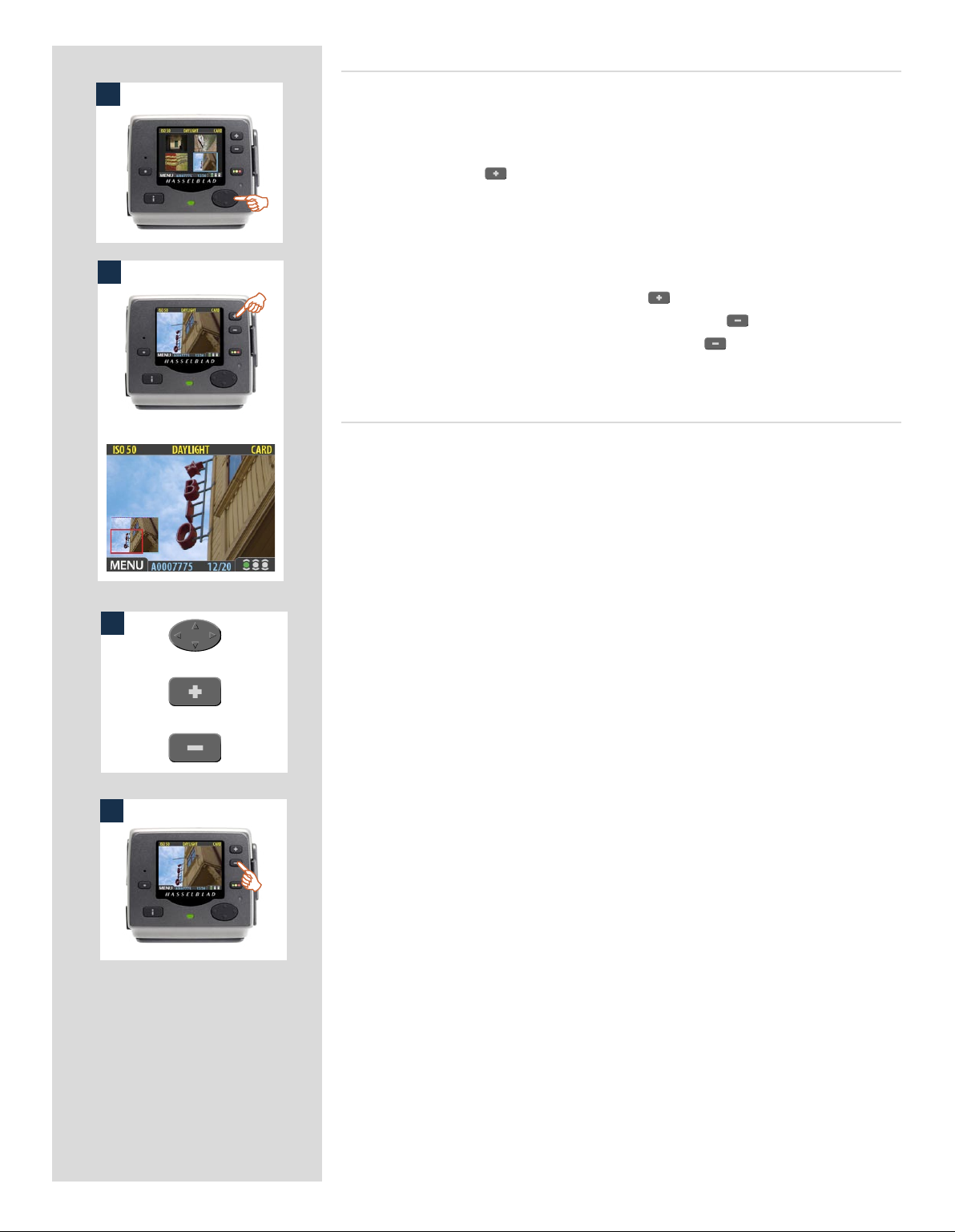
Zooming in for more detail
1
2
e preview display has a much lower resolution than your images. You can therefore
zoom very far into the images to inspect small details. To do this:
1. Browse to the image you wish to zoom into with the navigation button.
2. Press the zoom-in ( ) button to zoom in one step. The screen updates to show
both a zoomed image and a thumbnail image that includes a red box outlining the
portion of the images currently shown.
3. You can now do the following as needed:
• Use the navigator button to move the zoom area if you wish to inspect a differ-
ent part of the image.
• Zoom further by pressing the zoom-in ( ) button more times.
• Zoom back out one step by pressing the zoom-out ( ) button.
4. When you are finished, press and hold the zoom-out ( ) button to return to brows-
ing at the standard zoom level.
Thumbnail views
Preview thumbnails are small versions of each preview, sized to fit either four or nine
images on the screen at once. Use them to get an overview of your work so far and to
help find specific shots.
To see the thumbnails, start with the standard preview display and press the zoom-out
button once to see four thumbnails or twice to see nine.
When viewing thumbnails, the selected image shows a blue border. When an image is
selected, you can zoom in on it using the zoom-in button or delete it using MAIN MENU >
STORAGE > Delete (see also MAIN MENU > STORAGE > Delete for a detailed procedure).
Use and to scroll the thumbnails when you have more shots than can be shown.
3
If you continue to zoom out beyond the nine-thumb view, you will come to the batch
or
or
4
list and then to the media list. You can use this to select the current medium and batch
for browsing and for storing new images. See Working with Media and Batches for
details.
64
Page 65

You can cycle
through all the
available preview
modes by pressing
the View-Mode
button.
Preview Modes
Choosing the Preview mode
You can use the view-mode button to cycle through the available preview modes.
e preview screen works in several different modes:
• Standard preview:
shows a preview image surrounded by a display of few important settings.
• Histogram:
shows a preview image overlaid with a histogram.
• Histogram and full details:
shows a preview image overlaid with both a histogram and camera-setting details.
• Battery saver:
turns off the screen, but you can still use the menus and take pictures.
• Full-screen preview:
shows the preview only, with no frame or settings information.
To cycle through the various modes, press the view-mode button on the front panel. e
order is circular, as listed above. Each mode is described in detail in the sub-sections
below.
Regardless of the current mode, if you zoom in on the image or zoom out to the thumbnails,
the display reverts to showing the “standard” preview frame, which shows information
about the current image and camera settings around the edges. When you return to the
standard zoom level, however, you will then also return to your last-selected preview
mode.
Note that the screen can also operate in menu mode, which does not show a preview, but
enables you to make sensor unit settings. To enter menu mode, press the menu button.
See Working with the Menus for details.
65
Page 66

ISO setti ng
White balance
Current stor age medium
The standard preview display is the one
shown when you first turn on the camera
and is probably the view you will use most
often. It features a preview of your most recent shot and basic information about the
settings and the image itself. Several other
display modes are also available, including
histogram, capture details, full-screen and
battery saver. Please see Preview Modes
for details.
Button lab el
Image file name
A
Approval st atus and
browse filter setting
Storage capac ity
(Shots taken / shots remaining)
Fur thermore, the display enables you to
navigate the menu system and make camera settings; see Working with the Menus
for details.
Using the histogram
e histogram provides a graph that indicates the total number of pixels at each brightness
level, with brightnesses going from black on the le to white on the right. It is a valuable
tool for evaluating your exposure. A well-exposed shot usually has a full range of levels,
while under- and overexposed shots tend to show levels concentrated at the le or right
part of the scale, respectively.
Look at the histogram examples and the explanations below:
Underexposure A
A histogram that is cut-off at the le with few pixels elsewhere indicates a likely underexposure. Many details will be lost in the shadows.
Even exposure B
A histogram that is spread across the full range indicates a likely good exposure. ere
may still be a few pixels at the extremes, indicating a few spectral highlights and saturated
shadows, but this is oen normal in a good exposure.
Overexposure C
B
A histogram that is cut-off at the right with few pixels elsewhere indicates a likely overexposure Many details will be lost in the highlights
The histogram is only an indicator thast should be interpreted—there are many situ-
ations in which a questionable histogram will match an exposure that is perfectly fine
for the intended effect (and vice-versa).
Full-details mode D
In full-details mode, you can read a complete list of camera settings, plus see the histo-
C
D
gram and, in the background, a darkened preview of the image.
e camera-setting details are stored with the image, so you can refer to them using
FlexColor even aer you have loaded the image to your computer and stored it in your
archive.
66
Page 67

Battery-saver mode
In this mode, the sensor unit is fully responsive, so you can take pictures but the screen
is not lit up, thereby saving battery power.
You can enter the menu system while shooting in this mode (which activates the screen
until you exit the menu system again) but the approval, zoom and navigator buttons
have no effect.
You can also save battery power by turning down the brightness and/or contrast of the
display using the entries of the MAIN MENU > SETTINGS > USER INTERFACE > DISPLAY
menu. See ‘Making Display Settings’ for details.
1
Other ways to save battery power include setting a display time-out and/or a power-
down time-out (each of these is disabled by default). Use MAIN MENU > SETTINGS >
USER INTERFACE > Power Down to set a power-down time out. Use MAIN MENU >
SETTINGS > USER INTERFACE > DISPLAY > Timeout to set a display time-out. See also
‘Entries of the USER INTERFACE Menu’ and ‘Making Display Settings’ for details about
these settings.
Full-Screen Mode 1
In full-screen mode, you can browse your images at standard preview resolution without
2
any distracting data surrounding them.
Because the current approval setting is not shown in full-screen mode, the approval
button has no effect. is will prevent you from accidentally assigning the wrong status
without knowing it.
Overexposure indicator 2
ough the histogram shows you when some of your pixels are overexposed, it does not
tell you which ones. In a shot with many bright areas, it can be hard to know whether
the key parts of your image are just bright or completely overexposed. To help you find
them, the sensor unit can provide an overexposure indicator, which shows precisely
which areas of your shot are overexposed (i.e., pixels that are at maximum brightness,
thereby eliminating details).
When enabled, the overexposure indicator flashes the overexposed pixels from black
to white.
To enable or disable the overexposure indicator, use the MAIN MENU > SETTINGS >
USER INTERFACE > Mark Overexp. entry.
Please see Entries of the USER INTERFACE Menu for a detailed procedure.
Overexposure
indicator shortcut !
There is also a one-button shortcut for toggling the overexposure marker on and off.
To use it, press and hold
until the indicator is working
as you would like (enabled or
disabled).
67
Page 68

Delete shortcut !
There is also a one-button shortcut for deleting single images.
To use it, select a target image
and then press and hold the
until the confirm-delete dialog
opens.
Deleting images − general
e H2D/CFH enables you to delete images using any of the following techniques:
• Delete the currently selected image only.
• Delete all images from the current batch
• Delete all images from the current medium
• Delete all red-status images from the current batch
• Delete all red-status images from the current medium
• Delete all red- or yellow-status images from the current batch
• Delete all red- or yellow-status images from the current medium
Another way of working is to simply assign unwanted images as Red. In this way, you
retain the option (for a while) of changing your mind later while allowing the system
to automatically delete the unwanted images as the storage medium fills up.
You will always be asked to confirm each delete operation.
For complete details about how to use the menu system to delete single or multiple images, please see MAIN MENU > STORAGE > Delete.
Transferring images
Transferring to a computer
To transfer images stored on the compact-flash card to your computer, simply connect
the digital back to a computer using a FireWire cable and then run FlexColor, which will
automate the process. See your FlexColor manual for details.
See also Connecting to the Computer for details about how to connect to a computer.
Another way to transfer images to your computer is to remove the compact-flash card
from the digital back and insert it into a compact-flash card reader connected to a computer. See Using Compact Flash Memory Cards for details about how to remove and
insert the card.
e H2D/CFH can also function as a CF card reader for file transference. Select MAIN
MENU > SETTINGS> Misc > Interface > Disk.
Images that you have stored on an Imagebank can also be transferred to a computer by
connected the external disk to the computer with a FireWire cable and then copying the
files using the file system. See your Imagebank or hard disk documentation for details.
For complete details see MAIN MENU > STORAGE > Copy.
Transferring to an Imagebank
e H2D/CFH enables you to work in the field, shooting to the internal card, and then
transfer images to an external hard disk even if you do not have a computer with you. In
this way, you can combine the total flexibility of shooting without any external connections with the massive storage capacity of an external hard disk.
When the internal card gets full, just connect the camera to a Imagebank, transfer the
images, clear the card and return to shooting.
Images are not automatically deleted from the card aer copying. If you want to delete
some or all images to free up some space, then use MAIN MENU > STORAGE > Delete.
See also MAIN MENU > STORAGE > Delete.
68
Page 69

12
Menu:
• ISO
• White Balance
• Media
• Browse
Menu system overview
The main menu contains those settings that you will need to access most often as you work on an
assignment. It also provides sub-menus that give you access to all other settings, most of which you
will need less often.
Entry name (in white) and
current se tting in yellow
Sub-menus s how a rightpointing ar row, press the
right-arrow on the naviga-
tor butto n to open the sub-
menu (or, in some cases a
dialogue win dow)
- button label
(Here shown a s EXIT)
Current menu name
Selected entry (indicated by blue frame).
The + and − signs indicate that yo u can use
the (+) and (−) buttons to change the value
-button label
(Here shown i nactive)
Navigating the menu system
To enter to the menu system, press the MENU button on the panel. Any image visible is
then replaced by the first level of the menu. Use the navigator button to scroll through
the menu items and use the and buttons to change the selected setting. See also
The Control Panel for button diagrams and descriptions.
Any given menu may include both entries and/or sub-menus.
• Entries are settings that are available at the current menu level; they show their current settings next to the entry name. To make an entry setting, use the navigator ( ) button to
select the entry and then use the zoom ( and )buttons to select the desired option
for that entry
• Sub-menus do not have settings at the current level; they lead to another menu or dialog.
Sub-menus show a right-pointing arrowhead () instead of a value. To open a sub-menu,
use the up/down arrowheads ( and ) of the navigator button to select the sub-menu
and then press the right side of the button to open it. There can be several levels of submenus.
• When you are in a sub-menu, you can go back to the parent menu by pressing the left arrowhead () of the navigator button.
• Some sub-menus open a dialog. Dialogs require that you either make a setting or exit the
dialog (e.g., to confirm or cancel a delete command). The left arrowhead will have no effect.
69
Page 70

Menu structure
Entries of the main menu
70
Page 71

1 2
Language
1. Press the MENU button to open the menu.
2. Use and to select the SETTINGS sub-menu.
3. Press to open the SETTINGS menu.
4. Press to select the USER INTERFACE sub-menu.
3 4
5 6
1
5. Press either the or button to choose a new language
(in this case Spanish).
6. Press the MENU/EXIT button again to close the menu.
ISO
You are able to set the light sensitivity of the digital back to match
an equivalent ISO rating for standard film. e light meter inside
the camera body will use this setting when making automatic
exposure calculations for aperture and/or shutter settings.
e ISO rating can be set to 50, 100, 200 or 400.
To set the ISO:
1. Select the MAIN MENU > ISO entry. This is the top entry of
the top menu, so it will be selected by default when you enter
the menu system. (See also Navigating the Menu System for
details about how to find this setting.)
2. Use the or button to step through the available ISO
settings until the setting you want is shown.
3. Either move on to another setting by using the navigator button or press the menu button to exit the menu system and
keep your setting.
2
Note that the default sensitivity of the CCD sensor is ISO 50.
Higher ISO settings result in progressively noisier images (just
as higher ISO film becomes more grainy). It is recommended
that you use the lowest ISO setting possible for the lighting
situation.
3
71
Page 72

There are six ‘White Balance’ settings to choose from.
White Bal. Setting Setting descri ption
Daylight For general outdoor use in direct sunlig ht.
Cloudy Fo r general outdoor use in cloudy weather.
Shade For gener al outdoor use in shady locations out of direct sunlight.
Flash For general indoor use when using a normal flash system.
Fluorescent For use when using fluorescent lighting.
Tungsten For use when shooting indoors under standard tungs ten lamps.
White balance
Use this entry to set the white balance saved with the image and
applied to the preview.
To select a preset white balance:
1. Select the MAIN MENU > White Bal entry. The current
setting is displayed here. (See also Navigating the Menu
System for details about how to find this setting.)
2. Use the or button to step through the available white
balance settings until the setting you want is shown.
3. Either move on to another setting by using the navigator button or press the menu button to exit the menu system and
keep your setting.
Alternatively when using an H camera, you can set the USER button to ‘Grey bal. exposure’. A test exposure is then taken which
selects the central section of the image as the tone which you want
to equate with a neutral ‘white balance’.
Please note that white balance settings are for your viewing
convenience only. The setting is temporary for preview display
reasons and in no way affects the raw file which remains neutral
awaiting further processing.
Media
1 2
3
e storage setting controls where your digital back will store
new images and which stored images will be visible in the browse
window.
Oen, you have just one type of storage media available—the
internal compact-flash card. However, if you have several media
attached (e.g., a card and one or more external disks), then you
may need to switch between them.
If your selected storage medium has more than one batch (folder)
on it, then the batch selected when you use the storage menu entry
will be the one you most recently created.
To select the medium to which to save new shots and from which
to browse previous shots:
1. Press the MENU button.
2. Use and to select the MEDIA sub-menu.
3. Use the or button to step through the available media
until the name for destination/source you wish to use is
shown.
4. Either move on to another setting by using the navigator button,
or,
press the MENU button to exit the menu system and keep
your setting.
Note that you can also select media using just the (+) and (-)
buttons while browsing images. This method also enables
you to select a batch as you zoom in from media to batch to
thumbnails to preview. See Navigating Media and Batches
for complete details about this method.
72
Page 73

1
2 3
Browse
e browse filter complements the instant-approval system by
enabling you to browse through images according to their approval
status. You have the following choices:
• All: browses all of the images in the current batch, regardless of
their approval status. is is the default.
• Red: browses only red-status images from the current batch.
ese are images that you have marked for likely deletion.
You might browse these images to make sure you have not
eliminated any usable images and/or to find images that you
can delete to make room for new shots.
• Green: browses only green-status images from the current batch.
ese are either new shots that did not trigger an exposure
warning or shots that you manually assigned to green aer
overriding an exposure warning.
• Green & Yellow: browses green and yellow-status images, but
does not show red-status images. ese are probably images
that you have either decided to keep or not yet checked for
approval status.
For more information about using the instant-approval system,
please see Using Instant Approval Architecture.
Browse shortcut !
There is also a one-button shortcut for changing the browse
filter.
To use it, press and hold (do not
click!) the Instant Approval button until the approval status
colour appears. Browsing will
then only display the images
with that classification.
To set the browse filter using the menus:
1. Select the MAIN MENU > Browse entry. The current setting
is displayed here.
2. Use the or button to step through the filter options
(described above) until you have selected the filter you wish
to use.
3. Either move on to another setting by using the navigator but-
ton or press the menu button to exit the menu system and
keep your setting.
e appearance of the ‘Empty Browse Filter’ message signifies that
there are no images with that particular approval status.
73
Page 74

13
Menu: Storage
This section describes file storage,
file transference, storage organization, file classification and related subjects.
Navigating the STORAGE settings
74
Page 75

MAIN MENU > STORAGE
1
3
2
e Storage menu provides entries for working with storage me-
dia. Here, you can format media, copy images from the camera
to a hard disk or computer and create new batches on available
media. You can also set the initial approval status (green or yellow)
assigned to new pictures.
e first item on the storage list is file deletion. e great advantage
of digital capture is course the ability to judge images on the spot,
delete them immediately if necessary and thereby make room for
more valuable captures. ere are several ways to delete images:
• Delete a single image
• Delete all images from a batch
• Delete all images from a medium
• Delete all images of a specified approval status (e.g., red) from a
batch or medium
4
5
6
In this example, one image is to be deleted from a batch containing nine images.
To delete a single image:
1. From a preview image (which is being kept), use the but-
ton to go to the nine-thumbnail (in this case) view.
2. Use the navigator button to select the image you wish to
delete. When you are viewing thumbnails, the selected image
has a coloured border around it. When you are viewing single
images, the selected image is the one currently shown. (You
can delete an image either from single image view or from
thumbnail view).
3. Select MAIN MENU > STORAGE
4. Press to open the Delete dialog.
5. You are now shown a full-size preview of the selected image
and asked to confirm the delete. Press OK.
6. You now return to the main menu. Notice that the unwanted
image has now been deleted and the batch only contains the
three remaining images. Either move on to another image by
using the navigator button or press the menu button to exit
the menu system.
DELETE
75
Delete shortcut !
There is also a one-button shortcut for deleting single images.
To use it, select a target image
and then press and hold the
until the confirm-delete dialog
opens.
Page 76

Menus for deleting
several images from
a batch.
1
3
4
2
A.
B.
C.
D.
Deleting several images from a batch
To delete several images from a selected batch:
1. Starting at the single-image preview display, Select MAIN
MENU > STORAGE > Delete. (See also Navigating the
Menu System for details about how to find this setting.)
2. Use to enter the Delete submenu.
3. Use the or button to select:
A. This image - deletes the current image only
B. All red in batch - deletes all red images in the current
batch
C. All yellow/red in batch - deletes all yellow and red
images in the current batch
D. All in batch - deletes all images in the current batch
4. Press OK to confirm the delete (to exit without delete, press
EXIT).
76
Page 77

5. You now return to the main menu. Either move on to another
5
6
setting by using the navigator button or
6. Press the menu (EXIT) button to exit the menu system.
1
2
3
Deleting several images from a selected medium
To delete several images at once:
1. Starting at the single-image preview display, press the
button until you reach the media list.
2. Use and to select the medium from which you wish to
delete. You will be deleting from all batches stored on that
item.
Note that both each listed medium shows a set of three coloured
numbers in parentheses to the right of the medium name.
These indicate the total number of images of each approval
status (green, yellow and red) that exist on the medium. For
example, if you see a medium that shows (18/5/3), then the
medium contains a total of 26 images: 18 green (approved), 5
yellow (unclassified) and 3 red (marked for probable delete).
3. Select MAIN MENU > STORAGE > Delete. (See also
4
Navigating the Menu System for details about how to find
this setting.)
4. Press to open the Delete Image dialog.
77
Page 78

Menus for deleting
several images from
all batches from a
selected storage
medium.
5
6
5. You must now select the approval status that you wish to
delete. All images from the selected medium that are also of
the status that you select here will be deleted by the operation.
Use and to select All Red, All Red & Yellow or All.
6. Then press to open the delete dialog for your selected sta-
tus.
You are now asked to confirm the delete.
7. • To confirm, press the button to change the status to Yes and
then press the OK button to execute the delete.
7
8
• To cancel, press the menu button to exit; or press the button to
set the status to No and then press the OK button to cancel.
You now return to the main menu. Either move on to another
setting by using the navigator button or
8. Press the menu (EXIT) button to exit the menu system.
78
Page 79

FORMAT
1
e digital back is only able to read and write to media that have
been formatted.
However, new cards or disks sometimes arrive without any formatting, or you might want to convert media that are currently
using a format that the camera cannot read.
Each time you get a new compact-flash card, we recommend
that you format it using the digital back as described below,
2
3
4
5
even if the digital back is already able to read it. This will enable
the digital back to use the card more efficiently.
The digital back is capable of formatting any type of medium
connected to it, including compact flash cards and Imagebank
units. When you do this, you will erase all data contained on
the target medium.
You can also use the format command for the purpose of delet-
ing all images on a disk. This is sometimes faster than using the
delete function, but it is not as flexible because all data from
all batches will always be erased.
To format media:
1. If you have more than one type of medium connected (e.g.,
a compact-flash card and Imagebank), then start by selecting the medium you wish to format using the Storage entry
of the main menu (see also Selecting the Current Storage
Medium ).
2. Select MAIN MENU > STORAGE > Format. (See also
Navigating the Menu System for details about how to find
this setting.)
3. Press the to open the Format Card dialog.
4. You are now asked to confirm the operation.
• To confirm, press the OK button. This will execute the format
and delete all data on the current medium.
• To cancel, press the EXIT.
5. You now return to the STORAGE menu. Either move on to
another setting by using the navigator button or press the
menu (EXIT) button to exit the menu system.
79
Page 80

COPY
1
2
3
4
Usually, you will copy images from a card by connecting the camera to a computer and using FlexColor. However, you might also
want to load images from a card to a portable FireWire hard disk
or Imagebank, allowing you to erase the card and keep shooting
even when you do not have a computer with you.
Aer the copy, the destination disk will have a folder named
CARDXXX, where XXX is a number that increments with each
new copy operation (e.g., CARD001 for the first copy, CARD002
for the next, etc.). Previous copies are therefore never overwritten
(provided you have fewer than 1000 folders of them). Within each
CARD folder is a sub-folder for each batch. You cannot use the
digital back to browse images copied in this way; you must connect
the disk to a computer to browse the copied folders. is operation
does not delete the copied images from the card—you must do this
manually if you want to free card space aer the copy.
To copy images from the compact-flash card to external media,
use a FireWire cable to connect the external media to the H2D/
CFH and then.
1. Press the MENU button.
2. Press to navigate down and select the Storage dialog.
3. Press and then to navigate down and select the Copy
dialog. Press to open the Copy dialog.
If you have only one disk attached, then skip this step.
If you have more than one disk attached, then press to
select the From card to entry. Then use the or button to select the name of the medium you want to copy to.
5
Finally, press to go back to the Are you sure? entry.
With the Are you sure? entry selected, you must now con-
firm the operation.
• To confirm, press the (+) button to change the status to Yes
and then press the approve (OK) button to execute the copy.
• To cancel, press the menu (EXIT) button to exit; or press the
(-) button to set the status to No and then press the approve
(OK) button to cancel.
If you chose to confirm, then the H2D/CFH now tracks the
progress of the copy operation, which can take a few minutes. You can stop the copy at any time by pressing and holding the menu (STOP) button.
5. You now return to the STORAGE menu. Either move on to
another setting by using the navigator button or press the
menu (EXIT) button to exit the menu system.
80
Page 81

BATCH
1
2
3
Batches help you to organize your work. ey are very similar to
folders on a computer hard disk. Use the Batch command of the
STORAGE menu each time you want to create a new batch.
For more information about batches, please see Working with
Media and Batches .
To create a new batch:
1. Press the MENU button.
2. Press to navigate down and select the Storage dialog.
Press and then to navigate down and select Batch.
3 Press to open the Batch dialog. The new batch name will
always begin with a three-digit number, which automatically
increments by one with each new batch. Following this is five
letters, which you can assign yourself to help make the batch
easier to identify. To set the letters:
Use and to select one of the five letters. Then use the
or button to step the currently selected letter up or
down the alphabet until you have found the letter you want.
Continue working until you have set the name you want.
4. Press the approve (OK) button to save the new batch with the
name you selected.
5. You now return to the BATCH menu. Either move on to
another setting by using the navigator button or press the
menu (EXIT) button to exit the menu system.
Remember that all new images are stored automatically in
the latest batch. It is not possible to store new images in older
4
5
batches.
81
Page 82

DEFAULT APPR. LEVEL
1
2
3
4
e Instant Approval Architecture system helps you to evaluate and mark each image based on how well it has come out. By
default, the system assigns an initial approval status for each new
shot based on an analysis of the distribution of exposure levels. In
the factory configuration, the status of each new shot is assigned
as follows:
• Green (approved):
e new shot seems to have been exposed correctly.
• Yellow / Amber (unclassified):
e new shot seems to have been over- or under-exposed.
However, you might choose instead to override this system and
have all new shots assigned either as green or yellow, regardless
of the exposure analysis results. A typical strategy could be to assign all shots to yellow and then review all of the shots later and
promote only the best ones to green status. At the same time you
might demote the most doubtful shots to red status.
See also Using Instant Approval Architecture for complete details
about working with the approval system.
To change the default status assigned to each new image:
1. Press the MENU button.
2. Press to navigate down and select the Storage level.
Press and then to navigate down and select Default
Appr. level. Press to open the Default Appr. level dialog.
3. Use the or button to step through the available settings until the default status you wish to use (auto, green or
yellow) is shown.
4. Either move on to another setting by using the navigator button or press the menu (EXIT) button to exit the menu system
and keep your setting.
82
Page 83

14
Menu: Settings
There are a number of settings
grouped under the general
‘Settings’ heading which are:
• User Interface
• Camera
• Miscellaneous
• Default
83
Navigating the
USER INTERFACE
settings
Page 84

MAIN MENU > SETTINGS > User Interface
By altering the User Interface settings, you can control the way the digital back interacts
to suit you and your preferred way of working. It also includes date and time settings.
Entries of the USER INTERFACE Menu
e user interface menu includes both entries and sub-menus. e following entries are
available here:
• Language:
e menu system can be displayed in any of seven languages. is menu entry
enables you to select your preferred language for the menus.
• Power Down:
To help preserve the charge of the battery, you can set the back to power down
aer a specified period of inactivity. e effect is exactly the same as though
you had pressed the off button on the camera. Once it has powered down,
you must turn the H2D/CFH on before you can continue working. Set this to
Never to disable this feature (this is the default setting). Set to a value between
3 and 99 minutes to establish a time-out. (Note the difference between Display
‘timeout’ and Power Down.)
• Mark Overexp.:
is feature helps draw your attention to areas of your images that are overexposed. When this feature is enabled, the single-image preview display will
highlight each overexposed pixel by flashing it white and black.
Set this entry to On to enable the feature; set to Off to disable it.
• Sound:
e H2D/CFH uses audio feedback to help let you know if each new image is exposed correctly. is is described in Using Instant Approval Architecture.
is menu entry has Volume (choose between High, Low and Off), Key Click
(choose between On and Off) and Exposure Warning (choose between On
and Off).
• Date & Time:
e H2D/CFH has an internal clock that keeps track of the date and time.
is information is used to mark each shot with the date and time at which
it was taken. It is also used to label batches with the date on which each batch
was created.
• Display:
is feature sets the Timeout (2-30 seconds) on the display, which behaves
very much like a screen saver on a computer.When the timeout is reached, the
display will be turned off, but the back will still be running, so it will immediately respond to a press of the buttons. (Note the difference between Display
‘timeout’ and Power Down.)
is feature also sets the level of Contrast (on a scale of 1-10) on the display.
Usually, you should leave this set to the default level of 5; however in some
viewing environments and/or with some types of images you may wish to
increase or decrease this value. A value of 10 provides maximum contrast; a
value of 0 provides no contrast (a black screen). You can also help save battery
power by using a low value here.
is feature also sets the Brightness (on a scale of 1-10) on the display. is
sets the brightness shown on the screen. Usually, you should leave this set to
the default level of 5, however in some viewing environments and/or with some
types of images you may wish to increase or decrease this value. A value of 10
provides maximum brightness; a value of 0 provides minimal brightness. You
can also help save battery power by using a low value here.
84
Page 85

1 2
3 4
Setting the options under the User Interface menu
Each of the above entries can be set by similar menu navigation.
Language, Power Down and Mark Overex can be set immediately
by the or buttons while Sound, Date & Time and Display
require another move to sub menu for final choice.
Proceed as follows:
1. Press the menu (MENU) button to open the menu.
2. Use and to select the SETTINGS sub-menu.
3. Press to open the SETTINGS menu.
4. Press to select the USER INTERFACE sub-menu.
5. Use and to select the required entry.
Press either the or button to make the new settings in
the case of Language, Power Down and Mark Overex or
press again to access Sound, Date & Time and Display.
6. Press the EXIT button again to save the new settings and close
the menu.
5 6
MAIN MENU > SETTINGS > Camera (CFH only)
e CFH can also be used with view cameras (with the appropriate
adapter and cables).
e exposure time set on the CFH sets the maximum length of exposure. e default setting is 1/8 sec and this is the setting that can
be kept for all exposures from 1/8 sec through 1/2000sec. However,
this setting should be changed in accordance with the time required
if it exceeds 1/8 sec. Times of up to 32 seconds can be set.
If you prefer, you can connect the ‘Flash sync input cable’ between
the lens PC socket and the CFH which allows you to retain the
default setting of 1/8 second while still being able to use exposure
times longer than 1/8 second. is method also allows the use of
the B setting.
Model setting variations (CFH only)
When using the CFH with different models you should make the
appropriate setting change accordingly. Don’t forget to change the
setting again if you change camera model!
e four options are:
• H1
• H2
• Pinhole
Intended primarily for use in a studio environment where
complete darkness can be achieved and exposures made accordingly (also useful for ‘light painting’). In this mode the
CFH uses the exposure time (as well as other required stages
in a capture sequence) set in the Capture Sequence dialog.
e back can be triggered either via the START (MENU/
EXIT) button or from FlexColor (see later section for full
description of Capture Sequence settings procedure).
• Flash sync
For use with view cameras and a Hasselblad adapter.
85
Page 86

Connectivity diagram – CFH only
Navigating the
CAMERA settings
Hasselblad
CFH
View camera
adapter for
Hasselblad H1
(not available
from Hasselblad)
Flash sync
input cable
Hasselblad H2
Any view camera with
Hasselblad H1 adapter
Horseman ISS
electronic shut-
ter with lens
control
Any shutter
with X sync
Rollei electronic shut-
ter with lens
control
86
Page 87

1 2
3 4
5 6
Setting CAMERA model and options
Proceed as follows:
1. Press the menu (MENU) button to open the menu.
2. Use and to select the SETTINGS sub-menu.
3. Press to open the SETTINGS menu.
4. Use and to select CAMERA.
5. Press to open the CAMERA menu.
6. Press either the or button to select camera model.
7. Use and to select EXPOSURE TIME or CAPTURE SEQ.
if required.
8. Press either the or button to make new settings if
required.
9. Press the menu (EXIT) button to exit the menu system and
keep your settings.
7 8
9
Options available for PINHOLE and FLASH SYNC
Shutter Delay
e normal setting is Default and cannot be changed.
Exposure Time
is setting should be changed for cable-free exposure times longer
than 1/8 second, ensuring that it matches the set shutter speed on
the camera/lens. e settings range from 1/8 second to 32 seconds
(1/8 second is the default setting).
Capture Sequence
is feature functions in the same manner as an interval timer.
Initial delay: Controls the amount of time required to elapse
before the first exposure.
Delay: Controls the amount of time required between each exposure.
Count: Controls the total number of exposures required.
87
Page 88

1 2
Setting EXPOSURE TIME and CAPTURE SEQUENCE
Proceed as follows:
1. Press the menu (MENU) button to open the menu.
2. Use and to select the SETTINGS sub-menu.
3 4
5 6
7 8
3. Press to open the SETTINGS menu.
4. Use and to select CAMERA.
5. Press to open the CAMERA menu.
6. Press either the or button to select PINHOLE.
7. Press or to select EXPOSURE TIME.
8. Press either or to make an exposure time setting.
9
10
9. Press to select CAPTURE SEQUENCE.
10. Press to open the CAPTURE SEQUENCE menu.
88
Page 89

11 12
13 14
15 16
11. Press either the or button to make an INITIAL DELAY
setting.
This setting controls the amount of time that elapses
before the first exposure in the sequence.
12. Press to select DELAY.
13. Press either or to make a DELAY setting.
This setting controls the amount of time between each
exposure in the sequence.
14. Press to select COUNT.
15. Press either or to make a COUNT setting.
This setting controls the number of exposures in the
sequence.
17 18
19
16. Press OK to confirm all the settings.
17. The CFH is now ready for sequence start. Note that the MENU/
EXIT button now diplays START instead:
18. Press START to set the sequence running.
19. Note that the EXIT button now displays STOP. The sequence
can be stopped at any time by pressing this button and the
standard menu display returns.
89
Page 90

Navigating the
MISCELLANEOUS settings
MAIN MENU > SETTINGS > Miscellaneous
1
2
3
e MISCELLANEOUS menu contains two settings:
Selecting an interface
e interface setting controls the way the camera will appear to you
computer when you connect it. You have the following choices:
• Camera:
e camera will present itself to your computer as a
camera. Depending on the way you have configured
your computer, this may mean that when you connect
the camera, your computer will automatically launch
FlexColor, which may then begin importing images
and converting them to 3F format.
• Disk:
e camera will present itself to your computer as a mass
storage device. is means that it will look like a hard
disk, which you can navigate to, open and read using
the standard tools for your operating system (e.g., the
Finder in Mac OS or the File Explorer in Windows).
To set the interface presented by the digital back to your operating system:
1. Select the MAIN MENU > SETTINGS > MISCELLANEOUS >
Interface entry. The current setting is shown here. (See also
Navigating the Menu System for details about how to find
this setting.)
2. Use the or button to choose the interface you wish to
use (camera or disk) is shown.
3. Either move on to another setting by using the navigator button or press the menu (EXIT) button to exit the menu system
and keep your setting.
90
Page 91
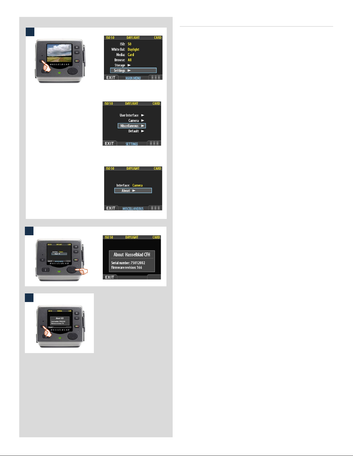
The About box
1
Occasionally, Hasselblad may release updates to the internal soware of the digital back (this is called “firmware”). ese updates
may fix small errors and/or add new features. You will probably
receive additional assistance from Hasselblad technical support
if and when a new update is available. In this case, it may be important to know the serial number and current firmware revision
of your digital back. To find this out:
1. Select MAIN MENU > SETTINGS > MISCELLANEOUS >
About. (See also Navigating the Menu System or details
about how to find this setting.)
2. Press to open the About dialog, which shows the serial
number and firmware version.
3. When you are done reading the information, press the menu
(EXIT) button to return to the MISCELLANEOUS menu.
Either move on to another setting by using the navigator button or press the menu (EXIT) button again to exit the menu
system.
2
3
91
Page 92
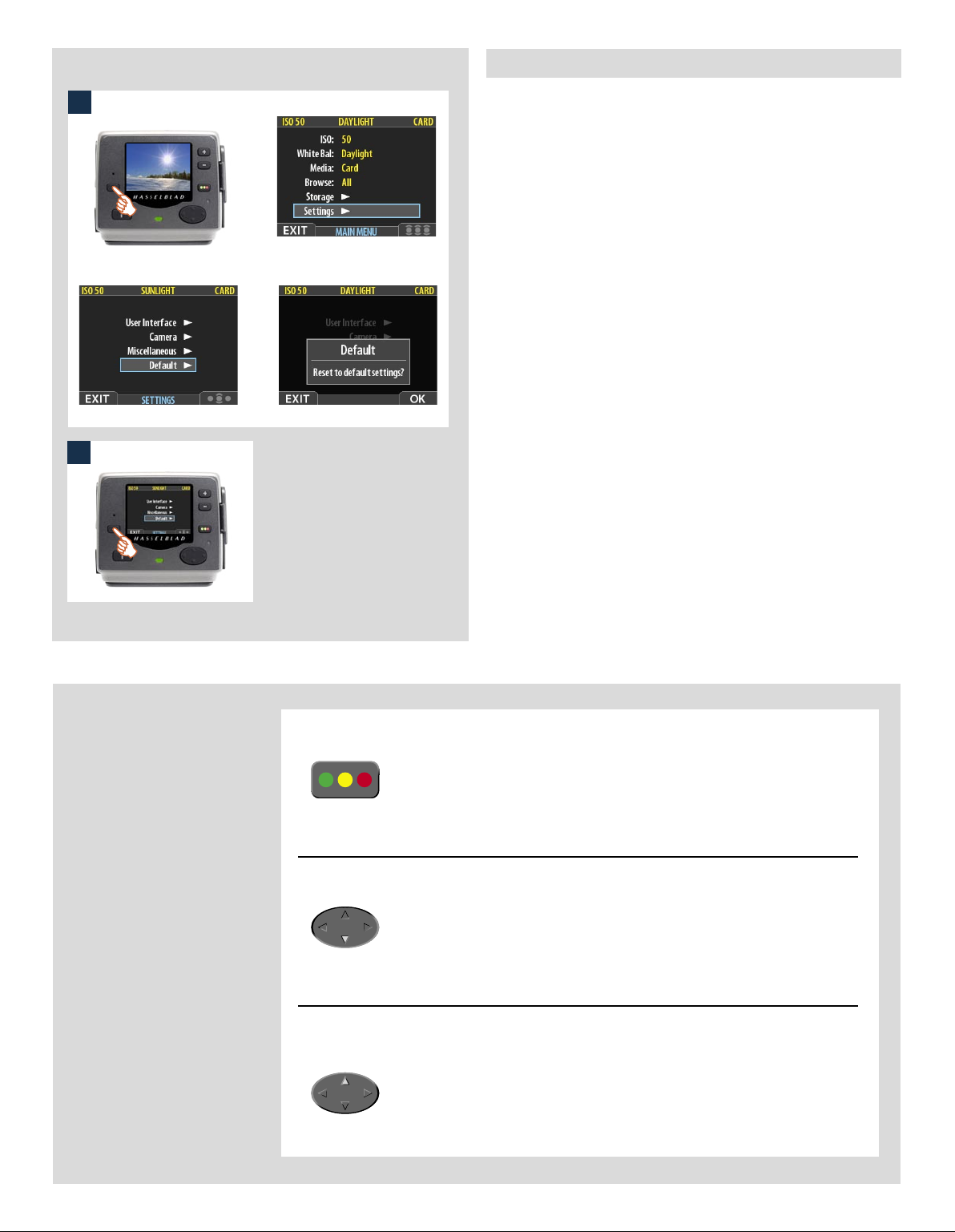
MAIN MENU > SETTINGS > Default
1
e DEFAULT setting will reset all custom settings you have made
back to the original default / factory settings.
To reset all settings:
1. Select the MAIN MENU > SETTINGS > DEFAULT entry.
2. Press the OK button and then the EXIT to return.
2
Don’t forget the
menu shortcuts!
To help you work faster, the digital
back provides shortcuts to some
of the most commonly used menu
commands that do not otherwise
have a dedicated button on the
front panel.
These are accessible by pressing
and holding one of the front-panel buttons for a second or so. These
are mentioned where appropriate
elsewhere in this manual, but we
summarize them here for your
convenience.
Try to memorize these quick
actions to save time and effort
later!
To set the browse filter
To delete images
To toggle the overexposure indicator
92
Press and hold until your preferred filter
is indicated.
See also ‘Using Instant Approval
Architecture’.
Select the target image and then press
and holduntil the delete dialog
opens.
See also ‘MAIN MENU > Delete’.
Press and holduntil the display begins
to flash (or stops flashing) its overexposed areas.
See also ‘Overexposure Indicator’.
Page 93

15
Light Metering
& Exposure Control
■ Three metering methods
■ Five exposure methods
■ Extremely accurate light metering
The light metering system is capable of selective sensitivity producing three reflective metering methods: Average,
Centre weighted and Spot. All methods are measured in increments of 1/12 EV. Information transfer is rapid and automatic ensuring consistently correct exposure settings even in
difficult and changeable lighting situations.
Light measurement is made through the lens (TTL) by the AE
viewfinder and exposure is controlled manually or automatically by the control wheels and/or settings. The information
is visible on both the grip LCD and the viewfinder LCD.
A great deal of control is available ranging from 100%
manual through to sophisticated fully automatic by way of
the various exposure methods: Manual, Aperture priority,
Shutter priority, Program and Program variable.
93
Page 94

Light metering and exposure control
Two primary factors have to be considered when making exposure control choice, namely, metering method and exposure method:
Metering method determines in which manner the light measurement is made and how much
of the image is taken into account( Average, Centre Weighted and Spot).
Exposure method involves the parameters and deciding factors about how the light measurement is translated into aperture and shutter speeds. Here the choice is about the camera controls
and their effect on the result or suitability for the subject. Included in this choice is the type of
automation too (Manual for 100% user control, Aperture priority, Program, etc for automated
control).
Some methods and modes are much more suited to various situations and applications than others, while some depend to a greater degree on personal preference and ways of working. A discussion of the points to consider in this context is beyond the scope of this manual. If you are not sure
about choice, please check in other general photographic literature for a fuller explanation. Also
check our website occasionally – www.hasselblad.com – for articles and discussions concerning
such matters.
Remember that all exposure configurations are only applicable to the ISO setting in use!
Since the light measuring system is TTL, filter factors, lens extension / extension ring factors, etc,
are automatically taken into account for average purposes. However, some combinations of
methods and equipment can cause slight discrepancies for various reasons and therefore for critical work you should make alternative exposures to suit personal preference.
Average
(45 x 37 mm) ≈ 95%
Centre weighted
(23 x 20 mm) ≈ 25%
Exposures are displayed on the grip LCD to within 1, 1/2 and 1/3 EV tolerances (de-
pendent on setting). This means that ‘half-stops’ are shown in a form that can differ
from more traditional displays. For example, the position between f/ 8 and f/11 is
displayed as f9.5 and likewise the position between 1/30s and 1/60s is displayed as
45. Therefore a display showing ‘f 9.5 45’ simply means ‘f/9.5 at 1/45 second’. The
appearance of an ‘s’ after the shutter speed signifies whole seconds so, for example,
‘45s’ on the display signifies an exposure time of 45 seconds, not 1/45.
Metering method
There are three metering methods available. All three are reflective methods (measuring the light
reflected off various selected parts of the subject according to method) and are through the lens
(TTL). These have the following designations (with their respective LCD symbols):
— Average
— Centre weighted
— Spot
Average: Commonly used for ‘average’ light situations where there is no particular dominance
of light or dark areas across the tonal range. Takes into account approximately 95% of the image
seen in the viewfinder.
Centre weighted: Emphasises the central section of the focusing screen equivalent to approximately 25% of the image. This provides a balanced assessment and is a typical choice where the
main subject is in the centre of the image.
Spot
(diameter 7.5mm) ≈ 2.5%
Spot: The sensitive area is equivalent to approximately 2.5% of the image area (the central spot
on the viewfinder screen). Any parts of the image outside of this area will not affect the exposure
reading. This provides a very accurate measurement of specific tones.Typically used in the zone
system and similar light measuring situations where maximum control is required. Also excellent for tonal comparison measurements. The spot mode can display ‘zones’ instead of EVs in the
viewfinder LCD (see Camera Options).
94
Page 95

1
�
�
2
Selecting metering method
Proceed as follows with the camera in active mode:
EXP
1. Press the EXP button on the viewfinder.
2. Turn the rear control wheel (in either direction 2a) to succes-
sively access the three choices: Average, Centre Weighted,
and Spot 2b.
3. Press Save (DRIVE button) to retain the setting.
3
Exposure method
Exposure can be controlled either manually or by using one of
four automatic modes. ese have the following designations on
the grip LCD:
M – Manual
A – Aperture (priority)
S – Shutter (priority)
P – Program
Pv – Program variable
In each mode you can see both the aperture and the shutter speed
information on the grip LCD and on the viewfinder LCD.
In manual mode, aperture is set by the front control wheel and
the shutter speed by the rear control wheel.
In the automatic modes, the aperture and shutter speed settings are
controlled by the camera, either partially or completely according
to setting. Within this mode there are four choices.
(Please see the Appendix for P and Pv mode charts that describe
the aperture and shutter speed setting combinations).
MANUAL EXPOSURE — M 1, 2, 3, 4
Manual mode will provide total user control of the shutter and
1
2
EXP
3
aperture settings.
To set the Manual mode, proceed as follows with the camera in
active mode:
1) Press the EXP button on the viewfinder.
2) Turn the front control wheel (either direction 2a) until you
reach M (Manual) 2b.
3) Press Save (DRIVE button) to retain the setting.
In this mode the shutter speed and aperture settings are manually
chosen by turning the front and rear control wheels.
e standard exposure setting is obtained when the pointer over
the exposure scale is positioned above the central index (in the
viewfinder LCD).
Any deviation from this standard setting is displayed by:
• the pointer appearing elsewhere than above the central index
and
• by figures above the scale representing the amount of
adjustment in EVs.
95
Page 96

�
A ‘+ 0.3’ above the scale in the display, as in illustration 4 for ex-
4
ample, would indicate a ‘0.3 EV overexposure’ setting. Conversely,
a ‘-2’ , for example, would indicate a ‘2EV underexposure’ setting. Note that the appearance of a +/- symbol on the grip and
viewfinder LCDs in manual mode means that a change has been
made to the exposure compensation setting. See later section on
‘Exposure compensation’.
e actual aperture settings and shutter speeds are indicated to the
right of the exposure scale in the conventional manner. (Note: ‘fullstops’, ‘half-stops’ and ‘third-stops’ are also displayed, according
to setting (see ‘increment setting). For example, a setting between
f/8 and f/11 will appear as f/9,5 if ‘half-stop’ is chosen).
AUTOMATIC EXPOSURE — A, S, P, Pv 1, 2, 3
EXP
2
Automatic exposure provides a choice of two ways of controlling
shutter speed and aperture settings semi-automatically and two
ways fully automatically:
Aperture priority: A - e aperture is manually chosen by
you by turning the front control wheel, and the shutter speed is
automatically chosen by the camera.
Shutter priority: S - e shutter speed is manually chosen by
you by turning the front control wheel, and the aperture is automatically chosen by the camera.
3
Programmed: P - In this mode, an aperture / shutter combination is chosen by the camera according to the EV measured
(metering method remains as your choice), though only within
pre-set appropriate limitations to suit various requirements and
applications.
Programmed variable: Pv - is mode is very similar to
Programmed, except with the additional parameters of lens focal length being automatically taken into account. For example,
long shutter speeds will automatically be avoided with a long focal
length lens.
1
To set one of the modes, proceed as follows with the camera in active mode:
1) Press the EXP button on the viewfinder.
2) Turn the front control wheel (either direction) until you reach
the required setting.
3) Press Save (DRIVE button) to retain the setting.
In Automatic mode the front control wheel selects alternative
combinations while maintaining the same EV and the rear control
wheel alters the amount of exposure compensation. e compensation appears as a +/- symbol on the grip LCD and viewfinder
LCD. Other combinations that are outside the parameters offered
by the Pv mode (but nevertheless still provide correct exposure)
are signified by a double arrow symbol appearing between the
aperture and speed settings on the grip LCD.
96
Page 97

AE- L button 1, 2, 3, 4, 5, 6
is button has two main functions that can be incorporated in
1
2
3
New metered area is 1.8 EV lower than the area metered
when the AE-L button was pressed.
4
AE-L button pressed to call the metered area ‘Zone 5’.
5
Metered area reads ‘Zone 8’.
6
Metered area above ‘Zone 10’.
various working methods involving exposure locking. It also has
an extra function for the flash meter capability (see AE-L section
under Flash). e AE-L button can:
a) lock an EV setting in manual and automatic modes.
b) be used as a brightness range checking facility in standard
terminology or Zone System terminology.
a) When the button is pressed (fig 1), the light metering facility is
locked to the EV setting at that moment. An L (= locked) symbol
appears between the shutter speed and the aperture indication
(fig 2) on the grip LCD and viewfinder LCD to confirm the status.
Press the AE-L button again to unlock (toggle function).
In the locked setting, the aperture and shutter speed become interlocked. In this way, a new aperture/shutter combination that
still represents the same EV, can be rapidly chosen. For example,
if you set the shutter at 1/125s and the aperture at f/8 and lock
them together, you can access new EV-equivalent combinations
of, for example, 1/30s a f/16 or 1/500s at f/4 just by moving the
front control wheel.
In practice this means you could, for example, in auto mode, position the metering area (spot setting) over an area in the subject
that you determine to be equivalent to a mid-grey and lock it with
the AE-L button. You can then recompose the picture with the
metering zone positioned over an area much brighter or darker
while still retaining the original exposure setting and choose a
new combination of aperture and shutter speed settings.
b) e AE-L button also allows the spot metering function to make
tonal comparison readings and brightness range checks. When the
AE-L button is pressed, the metered area is saved as a mid-grey.
When the spot area is then placed over another part of the scene,
the new area is then compared to the saved area and the difference
can be read off the scale seen in the viewfinder. For example, in
a landscape situation you could meter the foreground, lock the
reading with the AE-L button (thereby locking that area to be
reproduced as the equivalent to a mid-grey 18%), point the camera
at some rocks to see by how much darker they are compared to the
foreground by the EV difference read off the scale (illus 3).
If you have chosen Spot together with Zone display (see ‘Custom
options’ for settings and ‘Zone’ in the Appendix for further information about the zone system.) as well as one of the automatic
modes A, S, P or Pv, point the spot marking at an area that you
decide should be a Zone 5 and click the AE-L button (illus 4). e
meter will now display different parts of the subject as zone values
(illus 5) in the viewfinder LCD, instead of EV deviations, as you
move the spot marking over the subject. (Included are Lo and Hi
(illus 6)to signify areas beyond the range of the sensor).
Alternatively you can choose to re-classify an area as another zone
and then check the rest of the subject to see how other areas fall on
the zone scale. Do this by following the above procedure and then
turning the rear control wheel until you see the new desired zone
value in the viewfinder LCD. You will also see the new exposure
that will now produce that new zone. For example, you might have
measured a rock at zone 5 but wish to make it darker. By moving the
rear control wheel you could re-classify it as zone 4. You will then
be able to see, for example, whether white clouds are now falling
within the exposure range by their new Zone classification.
97
Page 98

�
�
Alternatively, you can also pre-set the initial zone reading in order
to save time and effort where there is no freely available ‘zone 5’
subject for light measuring. For example, you might be on a sandy
beach where you know that sand is normally classified as zone 6.
You can pre-programme the zone placement by holding down
the AE-L button while choosing the new zone value and turning
the front control wheel until zone 6 appears. Pointing the camera
at other parts of the scene will now display their zone values (in
relation to the initial setting of sand at zone 6) to see whether they
still lie within the sensitivity range and how they might appear
in the result.
Exposure compensation 1, 2, 3, 4, 5
e exposure compensation facility, for both manual and automatic
1
2
+/-
3
4
B
A
modes can be set from -5 to +5 EV, in 1/3 EV increments. is
facility will adjust the exposures by the set amount until changed
and the setting is visible above the scale in the viewfinder and as
a ± symbol on the grip LCD.
To make a fixed exposure compensation setting, proceed as follows
with the camera in active mode:
1) Press the +/- button on the viewfinder.
2) Turn either the front or rear control wheels to increase or decrease
the amount of compensation in 1/3 EV steps.
3) The amount is displayed in the viewfinder as both an EV figure
complete with a ‘minus’ or ‘plus’ prefix (A in illustration) , and
as a marker above a ‘minus’ to ‘plus’ scale with a central index
signifying zero compensation (B in illustration).
4) Press Save (DRIVE button) to retain the setting.
5) A ‘±’ symbol is then displayed between the aperture and shut-
ter speed setting as confirmation of the setting.
5
98
Page 99

16
General Functions
■ Manual and autofocus modes
■ Two drive modes
■ Quick adjust wheel
■ Profiles
This section describes the basic and general functions used in
most situations.
By understanding the capabilities of the H system you will be able
to gain a great deal of control of how you work in the future. By
taking advantage of the many features available, you might well
find your normal practices changing for the better. As all features
are user controllable, you tailor the way the camera works according to your preferences.
Features such as the Quick adjust wheel and Profiles, for example, do not have to be used of course, but you are advised to read
about them and see if they might suit your way of working.
99
Page 100

Power
The camera can be set at two active power modes − ON or
modes, battery consumption is least in
Standby
this interval can be changed in Custom Options. Also, after 10 seconds, the display on the OLED on
the sensor unit is dimmed and after 30 seconds the display is turned off completely. After 3 minutes
the sensor unit enters the Standby mode. Settings can only be made when the camera is in the ON
mode. (The sensor unit has its own standby setting)
mode automatically after 10 seconds (default) to preserve battery consumption but
Standby
mode and most in ON mode. The camera enters
Standby
− as well as
OFF
. In active
ON
To activate the camera press the red ON.OFF button until you see the start-up H2/D
logo appear on the grip LCD. e logo is automatically followed by the main screen.
e camera is now in ON mode.
Aer a set period of inactivity (programmable in Custom Options) the camera automatically enters Standby mode, signalled by the appearance of the H2/D logo again.
Standby
In this mode the camera is in a mainly inactive ‘standby’ mode and is ready to be immediately reactivated to the ON mode by:
• pressing the shutter release button half way
• pressing the Stop down button
• clicking the ON.OFF button
• pressing the Mirror up button.
In this mode, signalled by the standby H2/D logo appearing on the grip LCD, the
demand on the batteries is very low. It is ideal for general use where intervals between
shots exceed a few seconds.
Standby mode is automatically set from the ON mode aer 10 seconds (default) of
inactive use (programmable in Custom Options).
OFF
From the active screen, press (not click !) the red ON.OFF button for a half second. All
buttons (except the ON.OFF button) remain ineffective, producing minimal demand
on the batteries. is is the normal mode when transporting or storing the camera or
where there might be a risk of inadvertently activating the camera. (However, remove the
batteries if you are going to store the camera for a period of more than a few weeks).
In this mode neither the viewfinder LCD nor grip LCD information is available. e
magazine LCD, however, will continue to display information as it is independently powered. OFF mode is automatically set aer six hours of inactivity in Standby mode.
Manual focus
There is both a Manual Focus mode setting and a Manual Override capability. Manual
Focus is a specific setting that you actively make, whereas Manual Override is always available
as a temporary override of an autofocus setting.
In Manual Focus mode, focusing is carried out by rotating the focusing ring in the conventional
manner. The focus setting remains until changed as with a conventional non-autofocus lens. This
means that pressing the shutter release button will not activate a focus setting change as it does in
autofocus. To change back to autofocus, you must make a new setting (by pressing the AF button
and choosing AF S or AF C).
With Manual Override, you can manually alter a focus setting that has been made in the autofocus mode, by rotating the lens barrel in the conventional manner and without having to change
modes. As long as the shutter release button is kept at the half-press position, the new focus setting is maintained. By releasing the pressure on the shutter release button and pressing again, the
autofocus function is immediately reactivated.
100
 Loading...