

Page 1
USER MANUAL
for A6D Aerial
Page 2

INTRODUCTION
2
Page 3
Medium format photography is about professionalism. Camera
systems, their handling and captures have to be professional in
quality.
A6D User Manual
3
Hasselblad understands this and always strives to deliver it; professionals
know that too. The Hasselblad series of cameras consists of building new
developments on the shoulders of the previous generation. In this way all
the previous work-experience based and segment-demanding features are
automatically included. So, just when you think things can’t get much better,
they do. And the A6D is that model - all the good things from before and then
some!
The A6D heralds a step up that is noticeably greater than before. There are
changes and many are ‘from the ground up’. The A6D provides a reliable
connection to the eeting environment of digital imaging technology so when
the wind changes direction, the A6D remains as the safeguarding companion
to provide support.
Today’s aerial photography is more demanding than ever and Hasselblad
continues to rise to the occasion, introducing more and more advanced
products and applications for this exciting segment. This is especially true
of the Hasselblad A6D, the latest evolution of Hasselblad aerial cameras
designed for these specialist applications.
The new camera has been developed to deliver the image quality and
reliability required by our surveying and mapping customers. Listening to their
feedback we have developed a camera to encompass these needs and much
more.
There is no magical formula to Hasselblad’s success other than an
understanding of what is required to produce the best results available in the
world today, and an acceptance that there are no short cuts in this process.
Hasselblad does its best to produce the best; there is no other way to
achieve the Hasselblad star quality.
The A6D has been designed to corporate the latest technology available.
The heart of the system is the 53.4 x 40.0 mm 100MP CMOS sensor
delivering up to a staggering 15stops dynamic range and 16bit colour data.
The system boasts an ISO range from 64 to 12800 and coupled with the top
shutter speed of 1/4000th second allows the A6D huge exibility to adapt to
changing conditions whilst still delivering the image quality required.
Designed from the outset to be used in exible congurations the A6D can
be used as a stand alone single capture device or in grouped congurations
for pod based survey needs. Up to 8 cameras can be triggered within 20
microseconds of each other to allow accurate image alignment with minimal
overlap required.
Hasselblad’s best kept secret is knowing that every link in the chain that
leads to the clients nished image has to reach a certain standard; it is that
simple. That’s why Hasselblad puts so much time and energy into checking
those almost endless behind-the-scenes details and standards because we
understand this simple concept.
Completing the impressive specication, media storage is to CFast 2.0 or
SDXC cards. Tethered capture is available via the USB 3.0 Type C port. To
complete the family, the A6D is also available in NIR version, allowing both
NIR and CIR photography.
Page 4

CAMERA USER INTERFACE
For general operation of the user interface using the touch screen, please
refer to the full H6D user manual which can be downloaded from www.
Hasselblad.com
FIR M WARE U PDATES
If you have registered your camera you should automatically receive e-mail
informing you of the latest developments. Otherwise you are advised to make
regular checks regarding rmware updates to the camera.
The aim is to ensure you have the latest rmware updates for camera, which
naturally ensures the optimum in performance. When updating you should
also study the accompanying ‘Release Notes’ or ‘Read Me’ les where you
will nd details about improvements, developments and changes.
DISPOSAL
This product must be put in municipal waste. Check local regulations for
disposal.
A6D User Manual
4
Register your camera for regular news about the latest
developments, updates, news, tips, and much else!
– www.hasselblad.com –
Page 5

RESTRICTIONS AND RECOMMENDATIONS
Caution!
A6D User Manual
5
Caution!
Be careful when you use the camera. The camera is a precision instrument.
This will help prevent damage to the camera.
Caution!
Use protective covers as much as possible. The protective covers will help
prevent damage to the equipment.
Caution!
Use a protective case or camera bag when you transport the equipment. This
will help prevent damage to the equipment.
Caution!
Protect the equipment from oil fumes, steam, humid conditions and dust.
This will help prevent damage to the equipment.
Caution!
Seal all equipment in a plastic bag or similar if you enter damp and humid
condition from dry and cold condition. Wait until the equipment has
acclimatized to the new temperature before you remove the equipment from
bag. This will help prevent damage to the equipment.
Caution!
Avoid frequent and high temperature changes. This can cause damage to the
equipment.
Caution!
Keep camera and equipment away from moisture. If your camera becomes
wet, disconnect from electric power and let camera dry before further use.
This will help prevent damage to the equipment.
Store the equipment in a dry environment. This will help prevent damage to
the equipment.
Caution!
Be careful when you attach/detach the components to/from the camera. This
will help prevent damage to the data bus connections.
Caution!
Do not insert ngers into the camera body. This can cause damage to the
equipment
Caution!
Do not touch the CMOS Sensor with your ngers. The protective lter is very
sensitive. This can cause damage to the equipment.
Caution!
Keep all equipment out of reach of small children. This will prevent damage
to the equipment.
Caution!
Do not open the sensor unit. This can cause damage to the sensor unit.
Caution!
Do not try to remove the glass IR lter from the front of the CMOS (due to
dust or similar). This can cause damage to the equipment. Always contact
your local Hasselblad Authorized Service Centre.
Caution!
If you use canned compressed air to clean the glass of IR lter, be very
carefully before use. This will help prevent damage to the lter.
Page 6

CONTENTS
A6D User Manual
INTRODUCTION ...................................................................... 2
Camera User Interface ........................................................ 4
Firmware Updates .............................................................. 4
Disposal ............................................................................ 4
Restrictions and Recommendations ..................................... 5
GENERAL OVERVIEW .............................................................. 7
Parts and Components – overview ....................................... 8
A6D Lens Range ................................................................. 9
GETTING STARTED ............................................................... 10
Mounting the lens ............................................................ 11
Attaching the lens shield ................................................... 11
Attaching the adapter plate ............................................... 12
Power Connection ............................................................. 12
Synchronous connections ................................................. 12
USB & link to Phocus or SDK based application .................. 12
Saving images to a memory card ....................................... 12
Attaching the USB cable Lock ............................................ 13
CAMERA MAINTENANCE ...................................................... 14
Cleaning Sensor Unit & IR Glass ........................................ 15
TECHNICAL APPENDIX ......................................................... 16
A6D-100c Technical Specications .................................... 17
Lemo connector Signal Information .................................... 18
Electrical Timings ............................................................. 20
Coverage .........................................................................22
Coverage vs altitude ......................................................... 22
GSD vs altitude ................................................................ 22
Physical Dimensions ......................................................... 23
Accessories ..................................................................... 27
FCC Class A Notice for A6D-100c ...................................... 28
Battery Warning................................................................ 28
Index ............................................................................... 29
6
Page 7

GENERAL OVERVIEW
7
Page 8
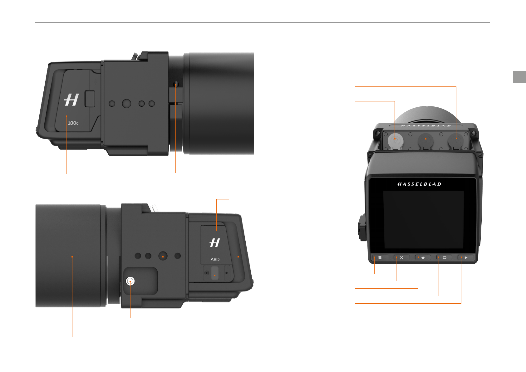
PARTS AND COMPONENTS – OVERVIEW
Lens mount locking boltStorage Media cover
Cover for External
Connections
A6D User Manual
8
Control connector B
Control connector A
DC Power connector
Lens release button
Mounting pointLens shield USB3 socket
Menu button
Soft button
Select button
Display button
Browse button
Digital capture unit
Page 9

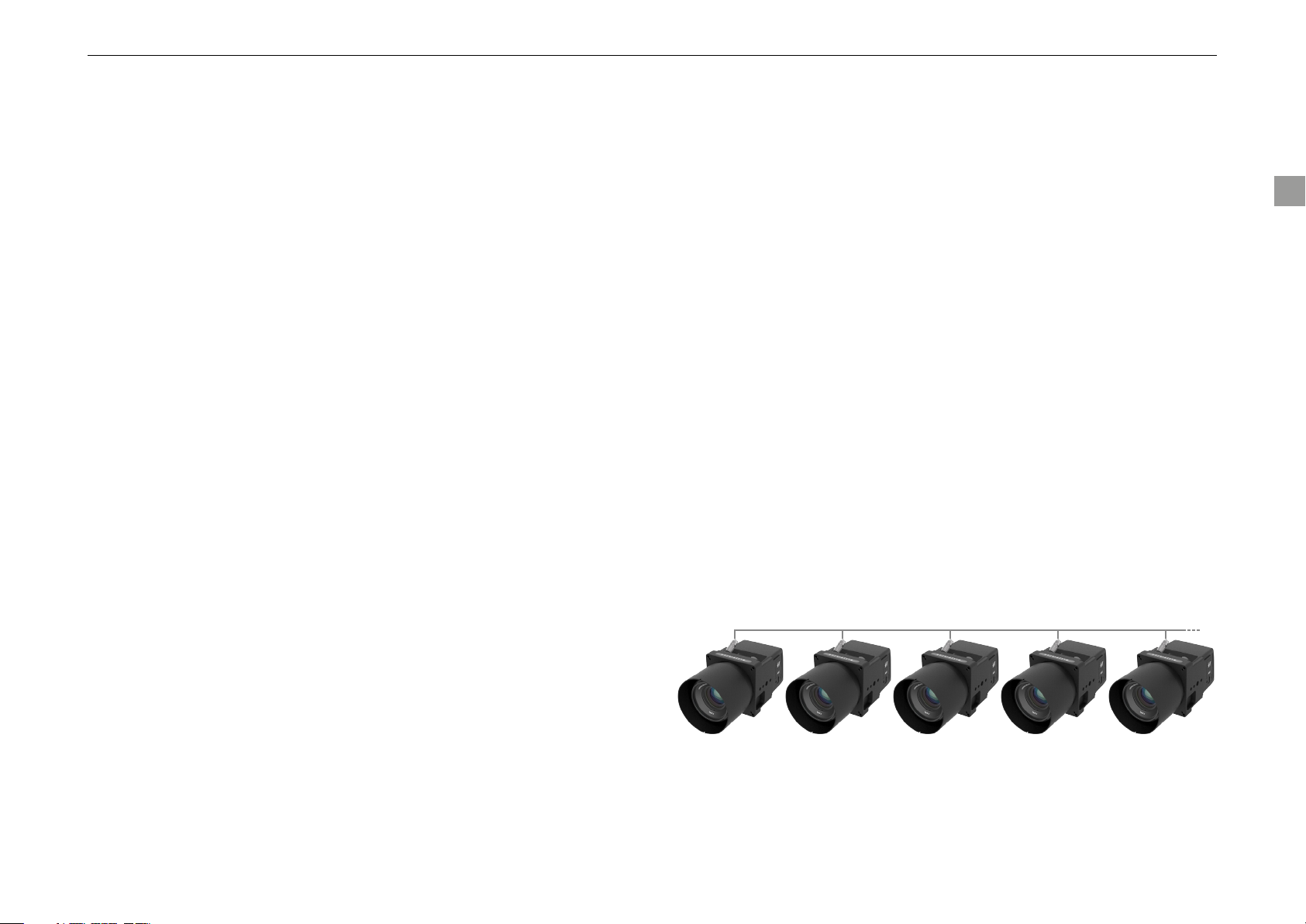
A6D LENS RANGE
A6D User Manual
All 9 focal lengths below are available in aerial versions with secure locking mounts to minimise vibration, exing and ensuring the image plane
and sensor stay parallel at all times. These units ship with focus xed at innity and rmware to close the shutter and aperture to their working
positions when power is applied to the camera.
Lenses Angle of View
(Diagonal)
HCD 4,8/24mm 104 Degrees 96 Degrees 80 Degrees 16mm 99mm x 100mm 810g 95mm 3014601
HCD 4/28mm 95 Degrees 87 Degrees 71 Degrees 19mm 102mm x 100mm 850g 95mm 3014602
HC 3,5/35mm 89 Degrees 75 Degrees 60 Degrees 24mm 124mm x 100mm 975g 95mm 3014603
HC 3,5/50mm-II 70 Degrees 56 Degrees 44 Degrees 34mm 116mm x 85mm 975g 77mm 3014604
HC 2,8/80mm 46 Degrees 37 Degrees 28 Degrees 55mm 70mm x 84mm 475g 67mm 3014605
HC 2,2/100mm 38 Degrees 30 Degrees 23 Degrees 67mm 80.5mm x 87.5mm 780g 77mm 3014606
HC 3,2/150N mm 26 Degrees 20 Degrees 15 Degrees 101mm 124mm x 86mm 970g 77mm 3014607
HC 4/210mm 19 Degrees 14 Degrees 11 Degrees 142mm 165mm x 85mm 1320g 77mm 3014608
HC 4,5/300mm 13 Degrees 10 Degrees 8 Degrees 196mm 198mm x 100mm 2120g 95mm 3014609
Angle of View
long side
Angle of View
short side
Equivalent 35mm
focal length
Dimensions
Length x Diameter
Weight Filter Thread
Item Number
9
HCD24 HCD28 HC35 HC50-II HC80 HC100 HC150N HC210 HC300
Page 10

GETTING STARTED
10
Page 11

GETTING STARTED
A6D User Manual
MOUNTING THE LENS
The A6D lens mount contains a locking mechanism that securely holds
1
the lens in place with an even pressure all around the barrel.
Before mounting a lens
ensure the plastic collar
is in position and the
joint is aligned with the
location lug.
To mount a lens, locate the red dot on the rear lens mount and ensure it is
2
facing upwards. Insert the lens into the camera body and rotate clockwise
until a click is heard.
To detach the lens,
press the lens release
button on the side of
the camera and turn the
lens anti-clockwise.
Insert the supplied 2.5mm Allen key into the bolt and rotate
4
clockwise half a turn to engage the lens mount lock.
NB: Do not overtighten as damage
to the lens mount may occur
ATTACHING THE LENS SHIELD
There are three lens shields
available depending on the lens in
use. To mount the shield for the
50, 80 or 100mm lens, simply
offer up the shield to the outer
lens mount and rotate the shield
clockwise until the shield locks.
11
Locate the lens mount locking bolt.
3
To mount the shield for the 35mm
lens it is rst necessary to mount
the adaptor ring to the existing outer
lens mount. This adaptor ring is held
in place with 4 screws.
Once this has been mounted, you
can attach the lens and then mount
the shield and secure it with a turn
in the clockwise direction.
Page 12

A6D User Manual
ATTACHING THE ADAPTER PLATE
To attach the A6D camera unit to an existing OEM camera mount
1
point you will need the adapter plate (P1). This plate is attached
to the camera body with 4 bolts. You must ensure that the plate is
correctly oriented – please see the image below and align the plate
correctly.
Secure the plate with the 4 supplied bolts, ensuring that you tighten
2
them one turn at a time to provide even pressure. Once the plate is
secure you can mount the lens. Attach the lens shield and the unit is
now ready to mount in the camera pod using the existing P1 bolt layout.
POWER CONNECTION
The A6D camera unit is equipped with three LEMO connectors. The grey
connector is the DC power connector. The unit requires a power source of
12-28 VDC to operate. This will normally be supplied via the aircraft power
system.
DC power connector
NB: Correct voltage AND polarity mus t b e
applied to the power connection or
damage to the camera will occur
Control
connector A
Control
connector B
SYNCHRONOUS CONNECTIONS
The remaining two connectors are used to synchronise additional
daisy chained camera units so that all exposures take place within 20
microseconds of each other. The centre connector is the signal input and
the right hand connector is the signal output for the next unit.
USB & LINK TO PHOCUS OR SDK BASED APPLICATION
Located on the left-hand side of the camera you will nd the USB socket.
Using the supplied cable and the cable lock ensures the connection will be
securely locked. Once the connector is locked in place and the other end
of the cable attached to your computer system, the camera should show
as connected and camera controls should be congurable via Hasselblad
Phocus software or your own application designed from the SDK.
12
SAVING IMAGES TO A MEMORY CARD
If you do not wish to transfer the captured images to a remote computer, the
CFast or SD card slots are available to allow in camera storage.
Page 13

A6D User Manual
ATTACHING THE USB CABLE LOCK
Insert the cable through the lock part and insert the cable into to the
1
USB port.
Attach the lock part and tighten the screws using the supplied 1.5mm
2
Allen key. Note that it needs to be oriented correctly to t.
13
Page 14

CAMERA MAINTENANCE
14
Page 15

CAMERA MAINTENANCE
A6D User Manual
CLEANING SENSOR UNIT & IR GLASS
If you see dark or colored spots or lines in your images, then you may need
to clean the outer surface of the sensor unit’s infrared (IR) lter. In most
cases, the careful use of compressed air will be adequate though if you use
canned compressed air, read the instructions very carefully before use to
avoid spraying impurities or even ice on the lter! Sometimes, however, small
particles will get stuck to the surface of the IR lter, requiring for a more
thorough cleaning, involving either uid or swab wipes.
If compressed air did not remove all the problems on the lter,
1
then use a long-handled swab style wipe (swab style wipes are
recommended due to the distance from the lens mount to the sensor
surface).
Ensure that the swab matches the width of the IR lter (if possible).
2
Apply rm pressure at the edge of the swab to ensure an even, rm
3
contact with lter surface. Wipe the surface in one unbroken motion.
Finally check if the IR lter has been properly cleaned either by visual
4
inspection by making a test capture. If further cleaning is needed,
repeat cleaning procedure.
15
Page 16

TECHNICAL APPENDIX
16
Page 17

TECHNICAL APPENDIX
A6D-100C TECHNICAL SPECIFICATIONS
Sensor Type CMOS, 100 mega pixels (11600 × 8700 pixels, 4.6 × 4.6 µm)
Sensor Dimensions 53.4 × 40.0mm
Image Size Stills: RAW 3FR capture 211MB on average. TIFF 8 bit: 289MB; Video: HD (1920 x 1080p), UHD (3840 x 2160p)
File Format
Shooting Mode Single shot stills, Video
Colour Denition 16 bit. Dynamic range up to 15 stops
ISO Speed Range ISO: 64, 100, 200, 400, 800, 1600, 3200, 6400, 12800
Colour Management Hasselblad Natural Colour Solution, HNCS
Lenses Any H System lens. Focus locked at innity on request.
Focusing Manual or Focus locked at innity
Storage Options CFast 2.0 card, SD card (UHS-I) or tethered to Mac or PC
Capture Rate (Based on
SanDisk Extreme PRO CFAST
2.0 Memory Card)
Storage Capacity 128GB card holds 576 images on average
IR Filter Mounted in front of sensor. NIR Option on request, CIR prepared.
Software Phocus for Mac and Windows. Phocus SDK for Windows available on request.
Platform Support Macintosh: maxOS version 10.11 or later ; PC: Windows 7 / 8 / 10 or later (64 bit)
Host Connection Type USB 3.0 (5 Gbit/s) Type-C connector
Additional Connections LEMO type connectors for power and camera control. Mini HDMI, Audio In/Out, Flash sync In/Out
Tethered Operation Supported in Phocus and Phocus SDK
Shutter Speed Range 0.5 sec to 1/4000 sec
Exposure Metering None
Power Supply 12-28 VDC required via LEMO connector
Operating Temperature -10 - 45 ˚C / 14 - 113 ˚F
Dimensions 100 x 100 x 151mm [W x H x D] Complete camera with HC80mm lens
Weight
(Body and sensor unit only)
Approval FCC (Class A), CE, RoHS, DO-160 section 8 - 15 - 20 and 21, CE, RoHS
Stills: Hasselblad 3FR, JPEG (12.5 MPixel)
Video: Hasselblad RAW (UHD, 25 fps), H.264 Compressed (HD, 25 fps)
60 Captures per minute.
1360g
A6D User Manual
17
Page 18

A6D User Manual
LEMO CONNECTOR SIGNAL INFORMATION
POWER CONNECTOR
Voltage Limit
Characteristics Symbol Value Unit (DC)
Maximum input voltage VSOH 28 V
Minimum input voltage VSOH 12 V
CURRENT LIMIT
The Power + signal will conform to the following current requirements:
Characteristics Symbol Value Unit (DC)
Typically average current consumption for Power + ICCA 1000 mA
Typically peak current consumption for Power + ICCP 2500 mA
Typically peak power consumption for Power + ICCP 25 Watt
It is recommended to use a Class II double insulated power supply, or a power limited external
batter y. The source should always be limited to a output power of no more than 100 watts in
total.
CONNECT OR PIN NVO.
Signal Name Power cable wire colour Signal description
1 GND White Power GND (-)
2 VCC Brown Main power (+)
MALE PLUG PIN-OUT
The below illustration shows the connectors pin-out seen from the solder
side of the male plug.
= Index Marker
CONTROL CONNECTOR A & B
The below table shows the connectors pin numbers, signal names and signal
direction in the control connector.
Connect
or pin no.
1 White CL Reserved for future use InOut I/O
2 Brown CH Reserved for future use InOut I/O
3 Green Vsys - 0 VDC Logic Supply - POWER
4 Yellow Vsys + + 5 VDC Logic Supply - POWER
5 Grey RX Serial channel, RX signal Input CMOS
6 Pink TRIG Trig Camera Input CMOS
7 Blue - BUSY Camera Busy Output OC
8 Red INTERNAL Reserved InOut -
9 Black - EXPOSE Shutter Open Output OC
10 Purple TX Serial channel, TX signal Output CMOS
Shield GROUND GROUND Chassis ground
Control
cable
Signal name Signal description Direction Type
CameraExternal flash
-
SYSTEM LOGIC SUPPLY SIGNALS
The VSYS+ power is always supplied to the control connector from the
Camera housing.
SYSTEM STARTUP
During system startup (when the main power is applied into the Camera
housing) the following requirements will apply for the System Logic supply
signal +VSYS:
Characteristics Symbol Value Unit (AC)
Maximum +VSYS voltage rise time TRVS 40 ms
18
1
1
2
8
2
7
9
10
3
6
4
5
Power Connector Control Connector A & B
The total capacitive load between +VSYS and -VSYS should not exceed the
following limit:
Characteristics Symbol Value Unit
Maximum capacitive load on VSYS CLVS 150 µf
Page 19

A6D User Manual
VOLTAGE LIMIT
The VSYS+ signal will conform to the following voltage requirements:
Characteristics Symbol Value Unit (AC)
Maximum output voltage VSOH 5.25 V
Minimum output voltage VSOL 4.75 V
CURRENT LIMIT
The VSYS+ signal will conform to the following current requirements:
Characteristics Symbol Value Unit (AC)
Peak current consumption for VSYS+ ICC 40 mA
VOLTAGE LIMIT
The electrical denition of signal type “CMOS” will be according to the limits
specied below:
Characteristics Symbol Value Unit (DC)
H level output voltage (min) VOH 4.0 V
L level output voltage (max @ IOL) VOL 0.4 V
L level output current IOL 4.0 mA
H level input voltage (min) VIH 3.5 V
L level input voltage (max) VIH 1.5 V
19
The electrical denition of signal type “OC” will be according to the limits
specied below:
Characteristics Symbol Value Unit (DC)
H level output voltage (max) VOH VSYS + V
Pull-up impedance R 10 Kohm
L level output voltage (max @ IOL) VOL 0.4 V
L level output current IOL 20.0 mA
TRIG, -EXP and -BUSY timing relationship
Characteristics Symbol Value Unit (AC)
Rise time (max) tR 1.0 µs
Fall time (max) tF 1.0 µs
TRIG pulse width (min) tTRIG 1.0 ms
Expose start (min) tSTART 100 µs
Expose start (max) tSTART 1 ms
BUSY start (min) tBUSY 0 ms
BUSY start (max) tBUSY 200 ms
ACTIVE time (min) tACT 1000 ms
ACTIVE time (max) tACT ∞ s
Mid expose pulse width (typ) tMID 100 us
Page 20

A6D User Manual
ELECTRICAL TIMINGS
The electrical timing when using EXPOSE signal as mid exposure indicator:
t
TRIG
t
R
TRIG
CENTRE OF
EXPOSURE
EXPOSE
20
t
F
t
MID
BUSY
t
EXP
t
BUSY
t
ACT
Page 21

A6D User Manual
The electrical timing when using EXPOSE signal as full indicator:
t
TRIG
t
R
TRIG
t
START
EXPOSE
21
t
F
t
EXP
BUSY
t
BUSY
t
ACT
Page 22

COVERAGE
A6D User Manual
COVERAGE VS ALTITUDE
The diagram below shows the ground coverage for the width of the image as
a function of altitude.
12000
11000
10000
9000
8000
7000
6000
5000
Altitude [ft]
4000
3000
2000
1000
HC150 HC100 HC80 HC50 HC35
0
0 1000
2000 3000 4000
Width Coverage [m]
GSD VS ALTITUDE
The diagram below shows the Ground Sample Distance as a function of
altitude.
12000
11000
10000
9000
8000
7000
6000
5000
Altitude [ft]
4000
3000
2000
1000
HC150 HC100 HC80 HC50 HC35
0
0 5
10 15 20 25
GSD [cm]
22
Page 23

PHYSICAL DIMENSIONS
A6D User Manual
23
(26.0) (123.8)
Page 24

PHYSICAL DIMENSIONS
A6D User Manual
3x 3/8” - 16
(14.0)
(10.0)
3x 1/4” - 20
(6x Ø5.2)
24
(14.0) (10.0)
(14.0) (21.25)
(26.0)(14.0)
Page 25

PHYSICAL DIMENSIONS
A6D User Manual
25
(Ø 107.0 )
Outer diameter of lens
tube for HCD24, HCD28,
HC35 and HC300
(Ø 98.0 )
Outer diameter of lens
tube for HC50, HC80,
HC100, HC150 and
HC210
( 4x M4 )
(83.0)
(90.0)
( 4x Ø4.1 )
(83.0)
(90.0)
(100.0)
(100.0)
Page 26

PHYSICAL DIMENSIONS
A6D User Manual
26
Total Length (See table below)
Lens Tube Diameter Total Length Requires Adapter
HCD24 107 mm 221.0 mm Ye s
HCD28 107 mm 221.0 mm Ye s
HC35 107 mm 247.5 mm Yes
HC50-II 98 mm 248.0 mm No
HC80 98 mm 205.0 mm No
HC100 98 mm 205.0 mm No
HC150 98 mm 248.0 mm No
HC210 98 mm 293.0 mm No
HC300 107 mm 322.5 mm Ye s
Page 27

ACCESSORIES
A6D User Manual
The following accessories are available for the A6D:
Item Description Item Number
Control Cable 3014532
Power Cable 3014525
Multi Sync Cable 3014533
Hand Release Cable 3014534
USB3 Cable, Type C - Type A, 2 m 3054177
Lens Protection Tube for 24mm Lens 3014506
Lens Protection Tube for 28mm Lens 3014506
Lens Protection Tube for 35mm Lens 3014521
Lens Protection Tube for 50mm Lens 3014522
Lens Protection Tube for 80 & 100mm Lens 3014523
Lens Protection Tube for 150mm Lens 3014522
Lens Protection Tube for 210mm Lens 3014507
Lens Protection Tube for 300mm Lens 3014508
Adaptor Plate (P1) 3014520
Hardcase 3014631
27
Hasselblad Warranty Options Item Number
Additional 1 Year Full Warranty 3014635
Additional 1 Year Warranty including loan Unit 3014636
Loan Unit Only 3014640
Page 28

FCC NOTICE
A6D User Manual
FCC CLASS A NOTICE FOR A6D-100C
This A6D-100c has been tested and found to comply with the limits for a
Class A digital device, pursuant to Part 15 of the FCC Rules. These limits are
designed to provide reasonable protection against harmful interference when
the equipment is operated in a commercial environment. This equipment
generates, uses, and can radiate radio frequency energy, and if it is not
installed and used in accordance with the instruction manual, it may cause
harmful interference to radio communications. Operation of this equipment
in a residential area is likely to cause harmful interference, in which case the
user will be required to correct the interference at his own expense.
BATTERY WARNING
Caution - There is danger of explosion if batteries are mishandled or
incorrectly replaced. On systems with replaceable batteries, replace only
with the same manufacturer and type or equivalent type recommended
by the manufacturer per the instructions provided in the product service
manual. Do not disassemble batteries or attempt to recharge them outside
the system. Do not dispose of batteries in re. Dispose of batteries properly
in accordance with the manufacturer’s instructions and local regulations.
Note that there are lithium batteries soldered on A6D internal boards. These
batteries are not customer replaceable parts.
28
Page 29

INDEX
A6D User Manual
A
Accessories ................................... 28
Adapter plate ................................. 12
Approval ........................................ 17
B
Battery Warning .............................. 28
Browse button.................................. 8
C
Cable Lock..................................... 13
Camera User Interface ...................... 4
Capture Rate ................................. 17
Cleaning ........................................ 15
Colour Denition ............................ 17
Colour Management ....................... 17
Control connector A .......................... 8
Control Connector A & B ................. 18
Control connector B .......................... 8
Coverage vs altitude ....................... 22
Cover for External
Connections .................................... 8
Current limit ................................... 19
D
DC Power connector ......................... 8
Digital capture unit ........................... 8
Dimensions ................................... 17
Display button .................................. 8
Disposal .......................................... 4
E
Electrical Timings ........................... 20
Exposure Metering ......................... 17
F
FCC Class A Notice for A6D-100c .... 28
File Format .................................... 17
Firmware Updates ............................ 4
Focal lengths ................................... 9
Focusing ........................................ 17
G
GSD vs altitude .............................. 22
H
Host Connection Type ..................... 17
I
Image Size ..................................... 17
IR Filter ......................................... 17
ISO Speed Range ........................... 17
L
Lemo connector ............................. 18
Lenses ...................................... 9, 17
Lens mount locking bol ..................... 8
Lens release button ......................... 8
Lens shield ................................ 8, 11
M
Menu button .................................... 8
Mid exposure ................................. 20
Mounting point ................................. 8
Mounting the lens .......................... 11
O
Operating Temperature ................... 17
P
Parts and Components ..................... 8
Physical Dimensions ...... 23, 24, 25, 26
Platform Support ............................ 17
Plug Pin-out.................................... 18
Power Connection ........................... 12
Power Connector ............................ 18
Power Supply ................................. 17
R
Register your camera ........................ 4
Restrictions and Recommendations ... 5
S
Saving images to a memory card ..... 12
SDK .............................................. 12
Select button ................................... 8
Sensor Dimensions ........................ 17
Sensor Type ................................... 17
Shooting Mode ............................... 17
Shutter Speed Range ..................... 17
Soft button ...................................... 8
Software ........................................ 17
Storage Capacity ............................ 17
Storage Media cover ......................... 8
Storage Options ............................. 17
Synchronous connections ............... 12
System Logic Supply Signals ........... 18
System startup .............................. 18
T
Technical Specication .................... 17
Tethered Operation ......................... 17
Total Length ................................... 26
Tube Diameter................................ 26
U
USB3 socket .................................... 8
V
Voltage limit ................................... 19
W
Weight ........................................... 17
29
Page 30

A6D User Manual EN v1.0.3 | 09-17
 Loading...