

Hasselblad 555ELD Service Manual
Service Manual
COPYRIGHT © 1999 ANDERS ENGSTRÖM
ANDERS ENGSTRÖM, ILLUSTRATÖR
Östra vägen 46
430 91 HÖNÖ
tel/fax 031-96 84 64
anders@aeillustr.se
555ELDOM.EPS
990215
Victor Hasselblad AB
Göteborg Sweden
May 1999

Contents list
Camera body 555ELD
1.
General
2.
Tools
3.
Disassembly
4.
Reassembly
5.
Adjustment, final assembly and calibration of the flash meter
6.
Sub-assembly: Front bayonet plate and auxiliary shutter
7.
Exploded view: Shell
8.
Exploded view: Motor housing
1.
9.
10.
11.
12.
13.
14.
15.
16.
17.
18.
19.
Exploded view: Right hand wall & main components
Exploded view: Left hand wall & electronics
Exploded view: Rear plate & auxiliary shutter
Exploded view: Front bayonet plate, mirror assembly & screen frame
Exploded view: Motor & electrical connections
Exploded view: Motor drive gear box
Exploded view: Shell 553ELX/500ELX
Exploded view: Motor housing 553ELX
Exploded view: Motor housing 500ELX
Exploded view: Right hand wall & main components 553ELX/500ELX
Exploded view: Left hand wall & electronics 553ELX/500ELX
20.
21.
22.
23.
Revision 0
Exploded view: Rear plate & auxiliary shutter 553ELX/500ELX
Exploded view: Front bayonet plate & screen frame 553ELX/500500ELX
Exploded view: Motor & electrical connections 553ELX
Exploded view: Motor & electrical connections 500ELX
May 1999

Contents list
Camera body 555ELD
24.
25.
Exploded view: Motor drive gear box 553ELX/500ELX
Exploded view: IR Release unit
2.
Revision 0
May 1999

555ELD - 553ELX - 500ELX
Related Service Infos
01/93
17/93
20/93
23/95
12/96
01/97
06/97
03/99
04/99
05/99
07/99
New screw holding the side cover - 553ELX and 500ELX
Fitted with wrong spacers - 553ELX
Redesigned flash metering circuit - 553ELX and 500ELX
New motor - 553ELX
Tripod foot adapter/kits
Rechargeable batteries discontinued - 500ELX
New tripod foot - 553ELX
Battery compartment - 553ELX
Release and S-arm redesigned - 553ELX and 500ELX
Preliminary spare part catalogue - 555ELD
New Service Manual - 555ELD
09/99
14/99
01/00
09/00
14/00
01/01
02/01
04/01
Mounting plate in motor housing modified - 555ELD
Battery compartment for AA batteries - 500ELX
New CD-ROM - Version 1.2
New CD-ROM - Version 1.3
Discontinued parts - 500 series cameras
Modified magazine hook - 555ELD
Modified motor unit - 555ELD
New CD-ROM - Version 2.0
Revision 3 January 2001

1:1
Camera body 555ELD
Camera type: Medium format single lens reflex camera with a built-in motor,
TTL/OTF flash metering and two release systems, one adapted
for conventional photography, the other one for digital
photography including integrated connections for digital
camera backs.
Camera body: One-piece, cast aluminium alloy shell with permanently
attached motor housing in lightweight magnesium. Tripod
socket threads 1/4" and 3/8", and tripod plate for rapid
mounting.
Film format and film 6x6 cm and 6x4.5 cm with different film magazines; 120 and
types: 220 rollfilm, 70 mm perforated long rolls and Polaroid film.
General description
Film advance: Automatic motorized film advance with simultaneous shutter
winding and mirror return; maximum speed 1.3 frames/s.
Remote shutter release via optional cord or IR control.
Lenses: All CF/CFi/CFE/CB lenses from 30 to 500 mm, Teleconverter
1.4XE, Converter 2XE, Converter 2XE, Teleconverter APO
1.4XE and PC-Mutar 1.4X Shift Converter.
Shutter: Lens leaf shutter. Speeds from 1 to 1/500 s and B. Time
exposure lever on camera body.
Shutter / Mirror modes: Five different shutter/mirror modes; single exposure with
normal mirror function, sequential exposures with normal
mirror function, pre-release of mirror for one single exposure,
repeated pre-release for single exposures and pre-release for
sequential exposures.
Flash control: TTL centre-weighted dedicated system with OTF metering.
Measured area Ø40 mm. Film speed range ISO 64 - 4000.
Controls a wide variety of flash units using appropriate adapters
(SCA-system).
Revision 0
May 1999

1:2
Camera body 555ELD
General description
Viewfinder and focusing Foldable focusing hood with 5x magnification, interchangeable
screen: with 90º or 45º prism viewfinders or magnifying hoods.
Bright Acute-Matte D* screen interchangeable for other types.
Full viewfinder image with all lenses and accessories.
Adaption to digital backs: Integrated databus connections interface directly to leading
digital backs. A unique release system with separate front
release port on camera activates the digital back.
Camera operation: Electronic front release. Alternatively, the camera can be
released remotely by optional cord or IR control. Selector dial
for shutter/mirror release modes. Film speed selector for
TTL/OTF flash metering. Battery check for alkaline batteries.
Battery/Capacity: Five standard 1.5 V AA size alkaline batteries (LR-6 or AM-3)
or rechargeable NiCd types. Up to 4000 exposures with
alkaline batteries, less than 2000 exposures with fully charged
NiCd.
Fuse: 5x20 mm 1.5 A medium slow-blow instrument fuse.
Dimensions: Length 120 mm (4.7"), width 100 mm (3.9"), height 150 mm
(5.9").
Weight: 1125 g (2 lb 8 oz).
○○○○○○○○○○○○○○○○○○○○○○○○○○○○○○○○○○○○○○○○○○○○○○○○○○○○○○○○○○○○
IR Release unit: Unit for infrared remote release of the Hasselblad 555ELD.
Attaches to the front release ports of the camera and powered
by the camera batteries. Can be set for normal or digital
photography. Supplied with the Hasselblad IR Remote control
44113, which in normal conditions provides an operating range
of approx. 10 m (33').
Dimensions: Length 26 mm (1.0"), width 86 mm (3.4"), height 36 mm
(1.4"), weight approx. 70g (2.5oz).
*Acute-Matte D designed by Minolta
Revision 0 May 1999

2
Camera body 555ELD
Tools
Tool No. Description Used for
V-2211 Pin driver Fitting the locating pin in the front plate
and the front gear bracket
V-2229 Focal length gauge Adjustment of the focal length,
mirror 45ºangle and focusing screen
V-2236 Microscope Focusing screen adjustment
V-4151/52 Focusing tester Focusing screen adjustment
V-4705 Focusing screen adapter Focusing screen adjustment
V-5423 Riveting jig Replacement of aux. shutter flaps
902474 Test box ELX/CX Calibration of the TTL flash meter
902658 Key angle gauge Adjustment of the front key angle
(V-2075)
903202 Power supply adapter Running the camera without batteries
970600 Service Test System Calibration of the TTL flash meter
Revision 0
May 1999
DIS01.EPS
990316
3:1
Camera body 555ELD
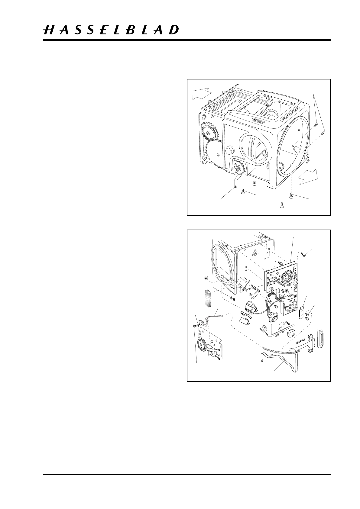
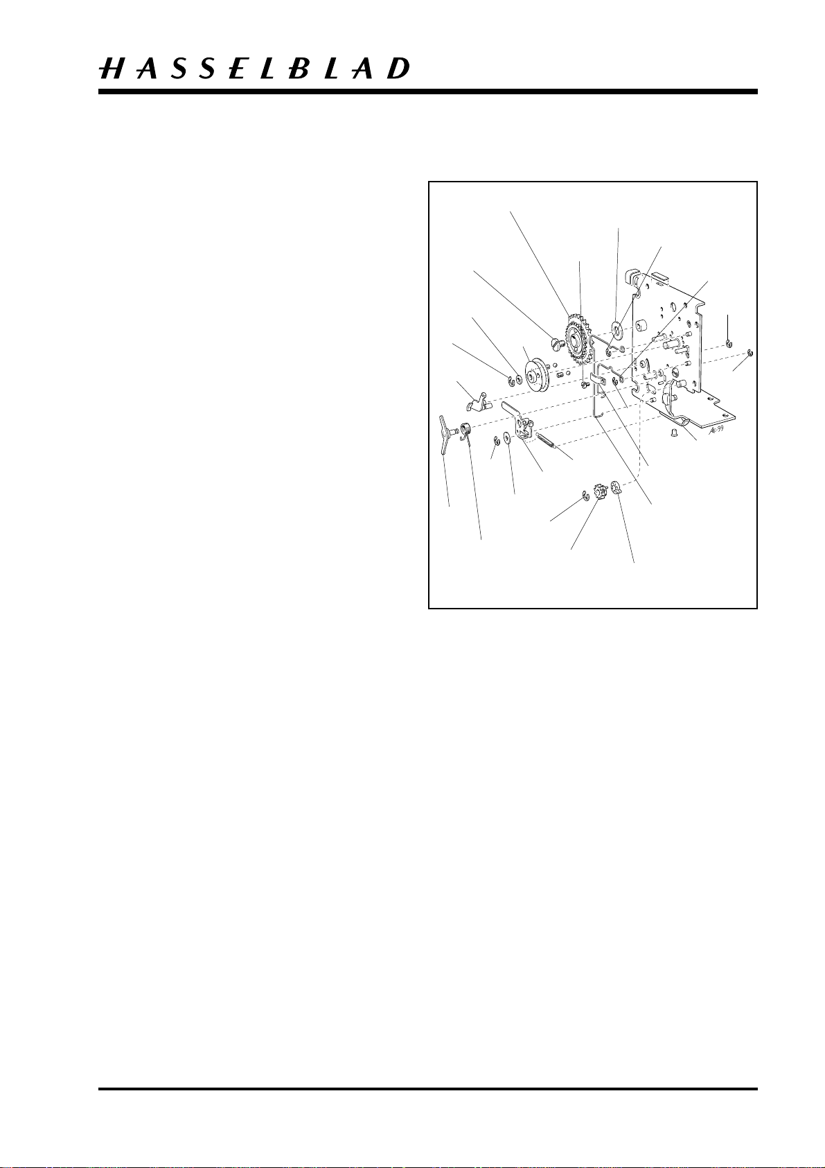
Motor Housing
Remove the lens, film magazine, viewfinder and
focusing screen.
Unlock the battery cover, operate the release button
and disconnect the battery cover at the exact moment
when the auxiliary shutter is closed and mirror is in
the upper position.
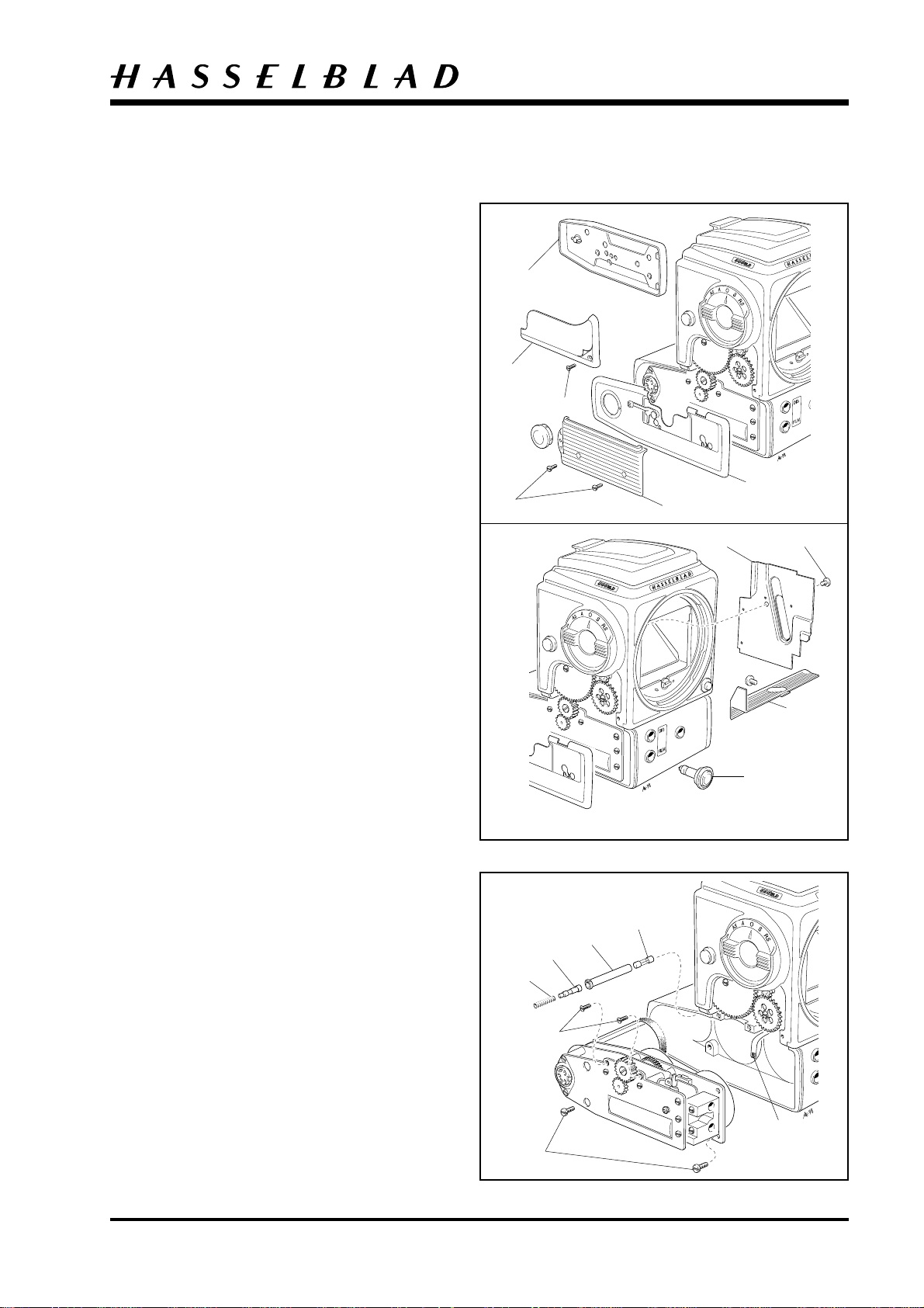
Peel back the small palpas cover hiding the screw
(821033). Use the short screwdriver V-2245.
Remove the inner side cover (22709).
Remove the cover (22928).
Fully wind the camera.
Remove the batteries and battery cover (30737
chrome or 30742 black).
30737, (30742)
30424-1,
(30631-1)
823017
820019
40202
Disassembly
21292, (22117)
22709
821033
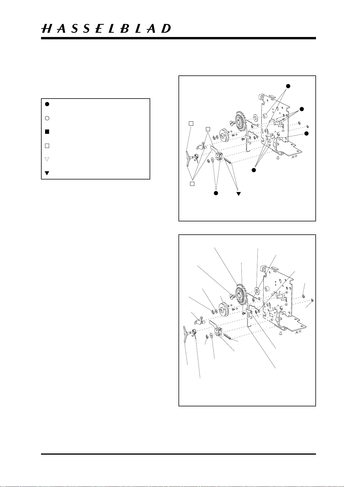
Remove the socket cap (22470) from the side contact.
Remove the two screws (820019) from the right hand
plastic grip (40202). Peel back the leather on the side
cover (chrome 30424 -1, black 30631-1) and remove
the screw (823017) underneath. The side cover and
the plastic grip can now be removed.
Remove the cover (Chrome 21292, black 22117)
from the motor housing.
Unplug the release button (46120) from the release
socket
Fig. 1.
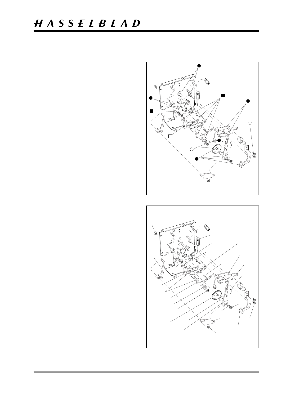
Remove the four screws, two (820042), two (823017)
and loosen the contact flex (22915) from the motor
unit and pull it clear of the motor housing. At this
point the fuse assembly (815855, 21305, 22342 and
13593) can also be removed. Finally, push out the
battery compartment (50178).
Fig. 2.
815855
DIS02.EPS
990316
21305
823017
22928
46120
Fig. 1
13593
22342
Revision 0
820042
DIS03.EPS
990316
22915
Fig. 2
May 1999
3:2
Camera body 555ELD
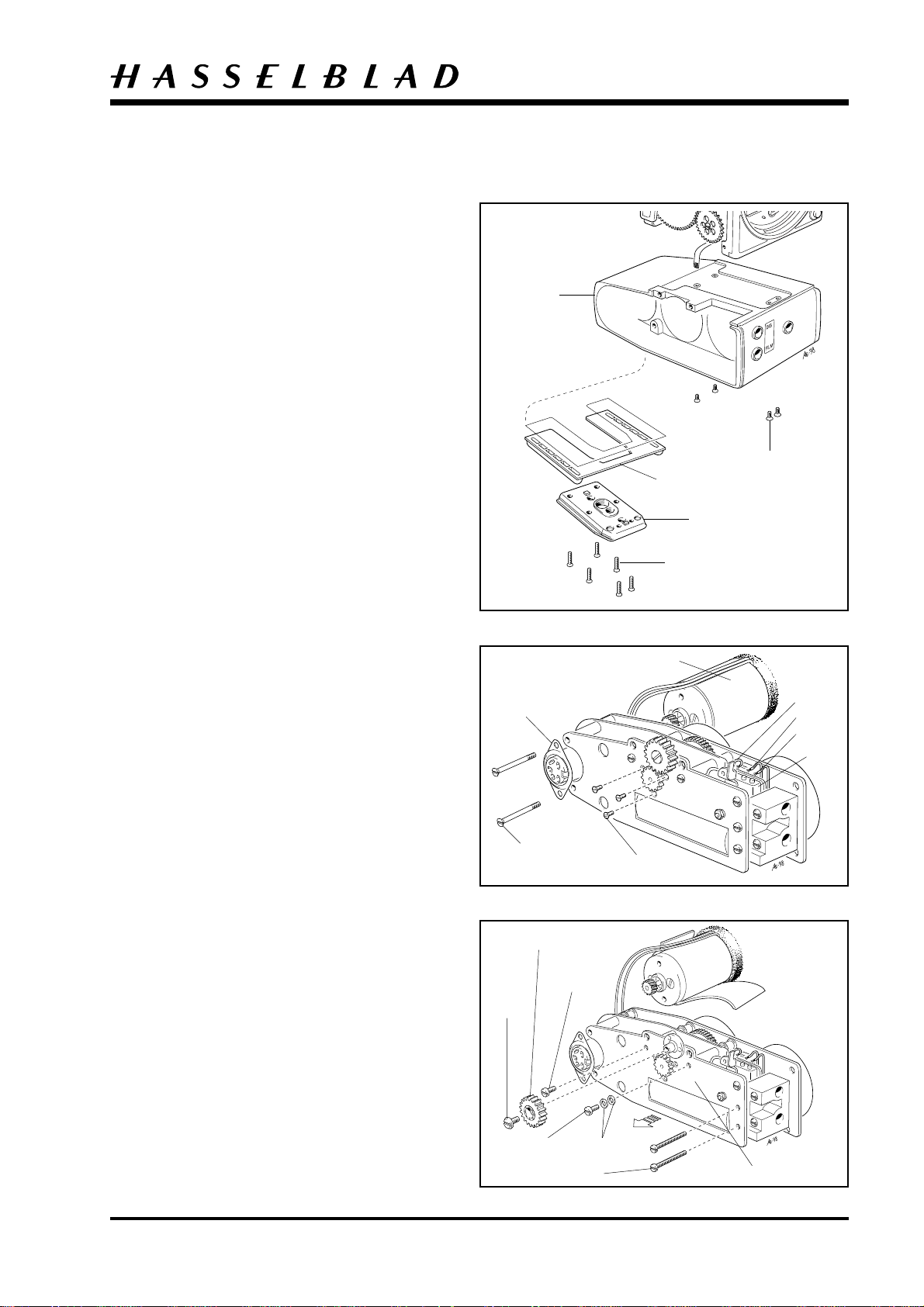
Remove the tripod foot (30763) by removing the six
screws (829790) and the rubber support (30778) held
by double-sided tape. When the tripod foot and the
rubber support have been removed, four holes are
exposed allowing access to the four screws (823745)
holding the motor housing (30801) to the main
camera body. Insert a screwdriver through the access
holes and remove all four screws. The motor housing
can now be removed from the main body of the
camera.
Fig. 3.
Disassembly
30801
823745
30778
30763
829790
Motor unit
Remove the to long screws (823049) from the side
contact (13604). The contact will now pull clear but
will still be connected to the motor (22827) and the
wiring. If no further disassembly is to take place, then
care should be taken that this wiring is not broken.
Unsolder the brown, red, and blue wire from the
micro switch (13605). Remove the three screws
(824205).
Fig. 4.
Remove the screw (821012) and the gear (13566).
Remove the two long screws (820048), that pass
through the outer mounting plate, then through the
connecting terminal and into the inner mounting
plate. Remove the two short screws (820041 and
820042) located on both sides of the gear (13566) and
the two washers (810613). Gently remove the outer
mounting plate (21290).
Fig. 5.
DIS04.EPS
990316
13604
DIS05.EPS
990406
821012
Fig. 3
22827
Brown
Red
Blue
13605
823049
824205
Fig. 4
13566
820041
Revision 0
820042
DIS06.EPS
990406
810613
820048
21290
Fig. 5
May 1999
3:3
Camera body 555ELD
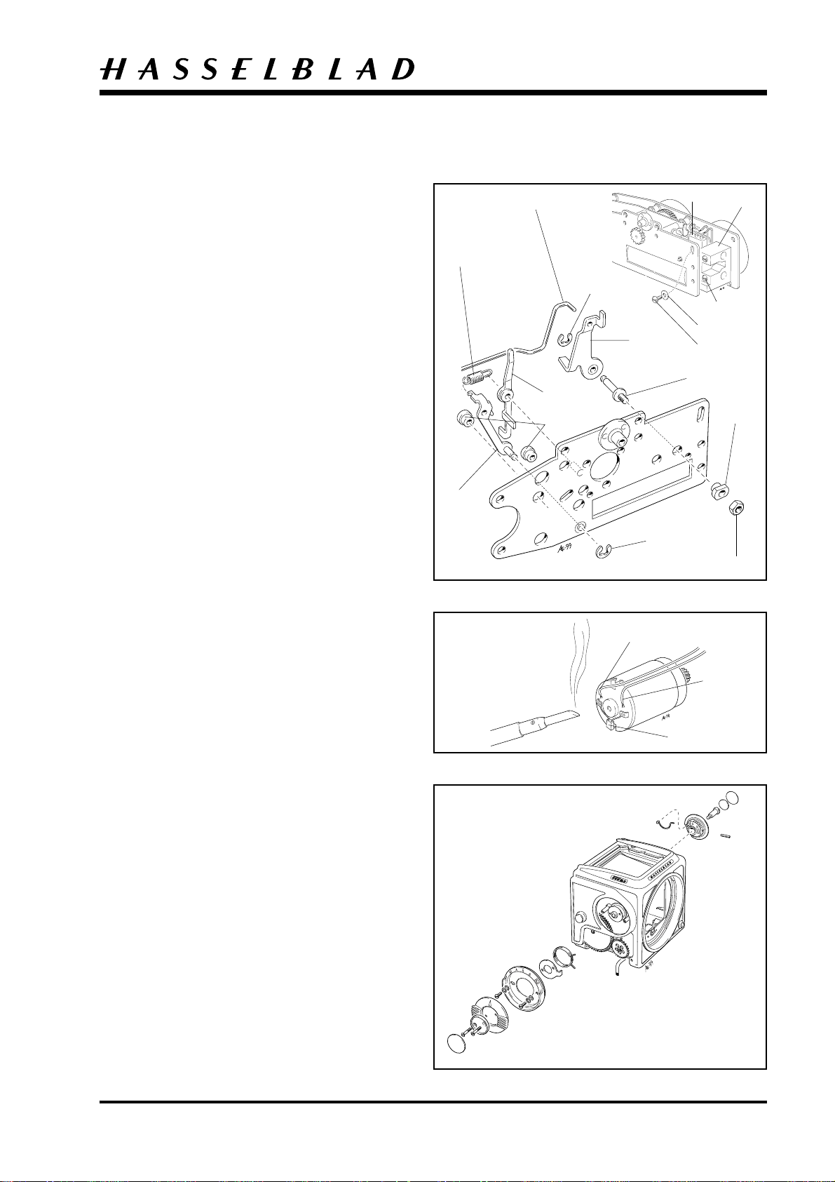
To remove the parts from the outer and inner
mounting plates proceed as follows (see the exploded
views 13 and 14):
Remove the small nut (828001), eccentric (22352)
and bearing pin (14100). Remove the screw (821033)
and washer (810532) and the micro switch (13605)
can be separated from the outer mounting plate.
Remove the link (22351), clip (817112) and stop arm
(13571). Disconnect the spring (814601), remove clip
(817115). Separate the magnet arm (13561) and the
clutch arm (14099) from the outer mounting plate.
Remove the two bearings (13528).
Remove the three plastic tubes (13606) from the
inner mounting plate. Remove the four screws
(821033) and disconnect the green, black, blue and
red wires from the connecting terminal (30435).
Fig. 6.
814601
14099
22351
13561
13528
817112
DIS08.EPS
990316
Disassembly
13605
13571
14100
30435
821033
810532
821033
22352
Remove the foam pad (22823). Unsolder the blue
wire from the sheet metal shield marked "+" of the
motor, the white wirer right opposite and the
capacitor (853549). The motor can now be separated
from the remainder of the motor unit.
Fig. 7.
Unloosen the screw (820020) and disconnect the blue
wire connected to the inner mounting plate (ground).
Lift carefully the PC board (22913) a bit and remove
the gears (13565, 13563 and 13564).
Unsolder the red wire from the contact spring
(22646) and separate the PC board from inner
mounting plate. Unsolder the solenoid (30421).
Camera shell
Remove the circular piece of leather (13374) from the
centre of the mode selector and then remove the two
screws (823023) beneath it. Withdraw the selector
knob (30429), thus exposing a further two screws.
Remove these two screws (820014) together with
their washers (810613) and (810607), and then
withdraw the symbol plate (30682), together with
the washer (13541) and spring (816906). Remove the
circular piece of leather (13374) on the ISO selector
(22495) and remove the set screw beneath it. When
withdrawing the selector care must be taken that the
spring loaded dog (22533) does not spring
free.
Fig. 8.
DIS20.EPS
990401
DIS07.EPS
990316
817115
828001
Fig. 6
Blue (+)
White (-)
853549
Fig. 7
Revision 0
DIS09.EPS
990316
Fig. 8
May 1999
3:4
DIS10.EPS
990505
DIS11.EPS
990316
Camera body 555ELD
Remove the two long screws (823781) located
towards the front of the camera shell. Remove the
two short screws (823755) located towards the rear of
the camera shell.
Remove the cap (22470) from the chassis connector
and peel back the leather (22455) covering the two
screws (823335). Remove these screws and push the
chassis connector into the body of the camera. The
shell can now be separated from the body.
Note: Care must be taken so that the flex (22915)
will not become damaged during the separation.
To accomplish this separation requires manipulation
of the shell and body in order that the gearing, on the
right hand wall of the camera shell, does not snag on
the camera shell. When the shell and body have been
separated the teflon button (103773) can also be
removed if required.
Fig. 9.
22915
823755
Disassembly
823335
823781
Fig. 9
Circuit board and contact flex
CAUTION! When handling the circuit board a
grounded bench mat and a wrist strap must be used to
prevent ESD damage.
Remove the screw (820019) and the washer (810407)
that secures the micro switch (852589). Loosen
carefully the cables (22931) from the chassis. Remove
the two screws (820011) from the grounding
attachment (22918). Remove the screw (820011) that
secure the cable holder (12453). Remove the two
screws (820325) that secure the photodiode and the
two screws (820015) that secure the PC board.
Loosen carefully the contact flex (22915) from the
bottom side of the chassis. The circuit board, also
secured by double-sided tape, can now carefully be
separated from the assembly.
Fig. 10.
820325
810407
820019
22931
Double-sided tape
820015
22918
820011
22915
Fig. 10
Revision 1
February 2000
3:5
Camera body 555ELD
Rear plate
Remove the screw (821033) from the centre of the
large gear (13557) and lift the gear clear. With the
gear removed an additional screw is exposed which
must also be removed (820025). Remove the screws
(820013 and 820015) securing the rear plate to the
left hand wall, the two screws (820015) on the
underside and the screws (821017) on the upper side.
Release the camera.
Remove the clip "A" (817115) located in the centre of
the actuating part (13551). Tension the camera
somewhat by turning the gear (13556) clockwise and
pull out the rear plate approximately 10 mm. Remove
the clip "B" (817115) that secure the upper actuating
arm (13580) and disconnect it from the actuating
part. Lift the actuating part clear of its stud. Keeping
track of the spacer (13547), the rear plate can now be
separated completely from the remainder of the
assembly.
Remove the two screws (105412) and the two springs
(815511). The contact flex (22915) can now be
separated from the rear plate.
Fig. 11.
105412
22915
DIS13.EPS
990505
815511
820013
820015
"B"
"A"
13551
13580
820015
Disassembly
821017
13547
820025
13557
13556
821033
Fig. 11
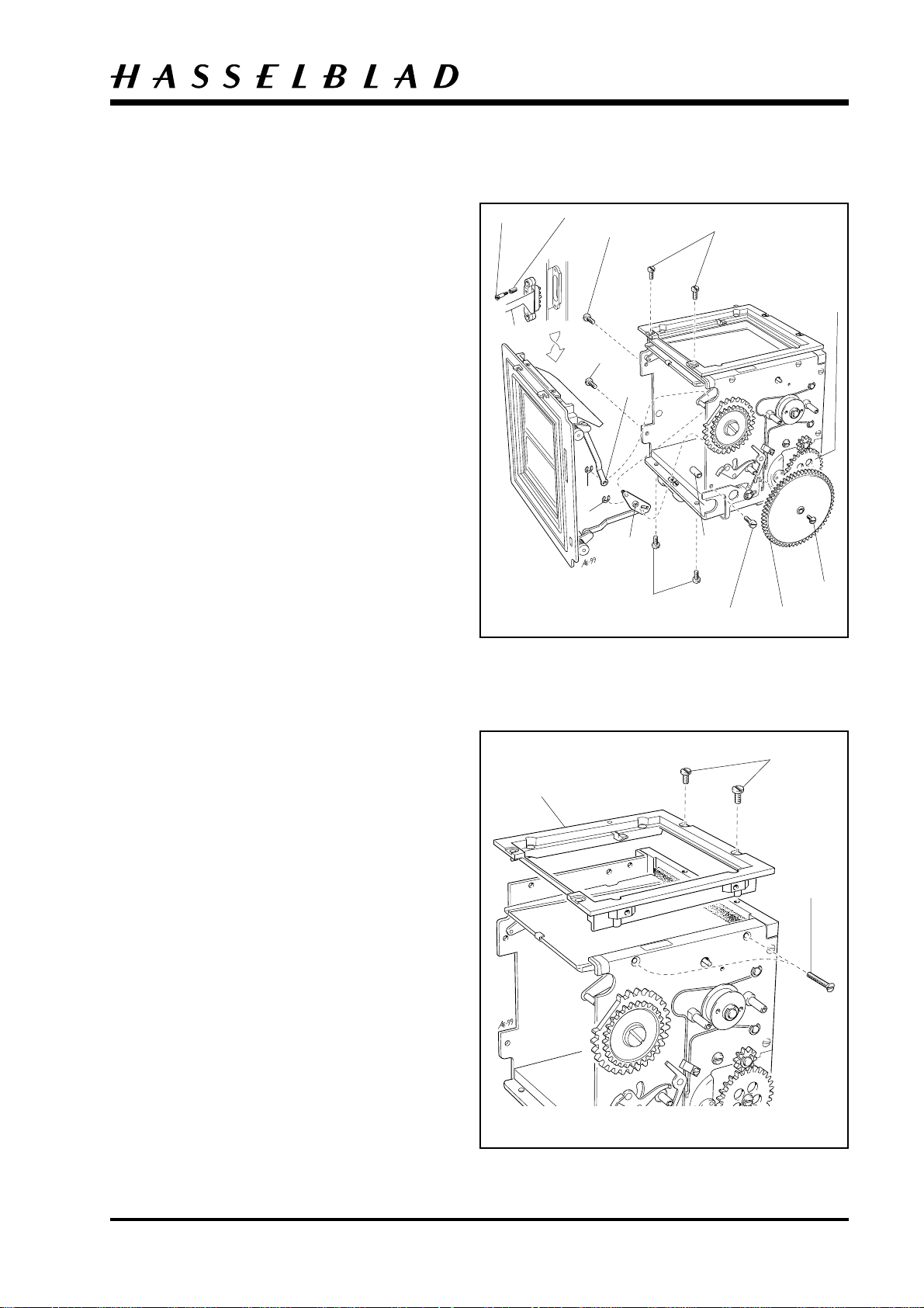
Focusing screen frame
Remove the two long screws (823028) that secure the
frame to the side walls. Remove the screws (821017)
that secure the frame to the top of the camera body.
The frame (22980) can now be separated from the
remainder of the assembly.
Fig. 12.
DIS14.EPS
990316
821017
22980
823028
Fig. 12
Revision 0
May 1999
3:6
Camera body 555ELD
Mirror
Disconnect the mirror hinge (30754) from the two
pins "A" and release the pin "B" on the mirror frame,
from the mirror lever (22460). The complete mirror
(30716) can now be separated from the remainder of
the assembly.
Fig. 13.
Disassembly
"B"
"A"
DIS15.EPS
990316
Fig. 13
Front bayonet plate
Remove the two screws (820015) located at the rear
of the bayonet plate. Remove the two screws
(823655) that secure the bottom of the bayonet plate
to the main camera body. Remove the two screws
(823015) that secure the bayonet plate to right hand
wall of the camera body (i.e. the side upon which the
mode selector is mounted).
When separating the bayonet plate from the rest of
the camera body a firm grip should be maintained on
the gear (13556), thus ensuring that tension on the
spring behind it is not quickly relieved.
When the bayonet plate has been separated from the
rest of the camera body the gear should be gradually
released allowing the tension on the spring to be
gradually relieved. Remove gear (13556) and disc
(21324)) with screw (821033) from bayonet plate.
Fig. 14.
823015
DIS16.EPS
990505
821033
820015
823655
21324
13556
Fig. 14
Revision 0
May 1999
3:7
DIS18.EPS
990316
Camera body 555ELD
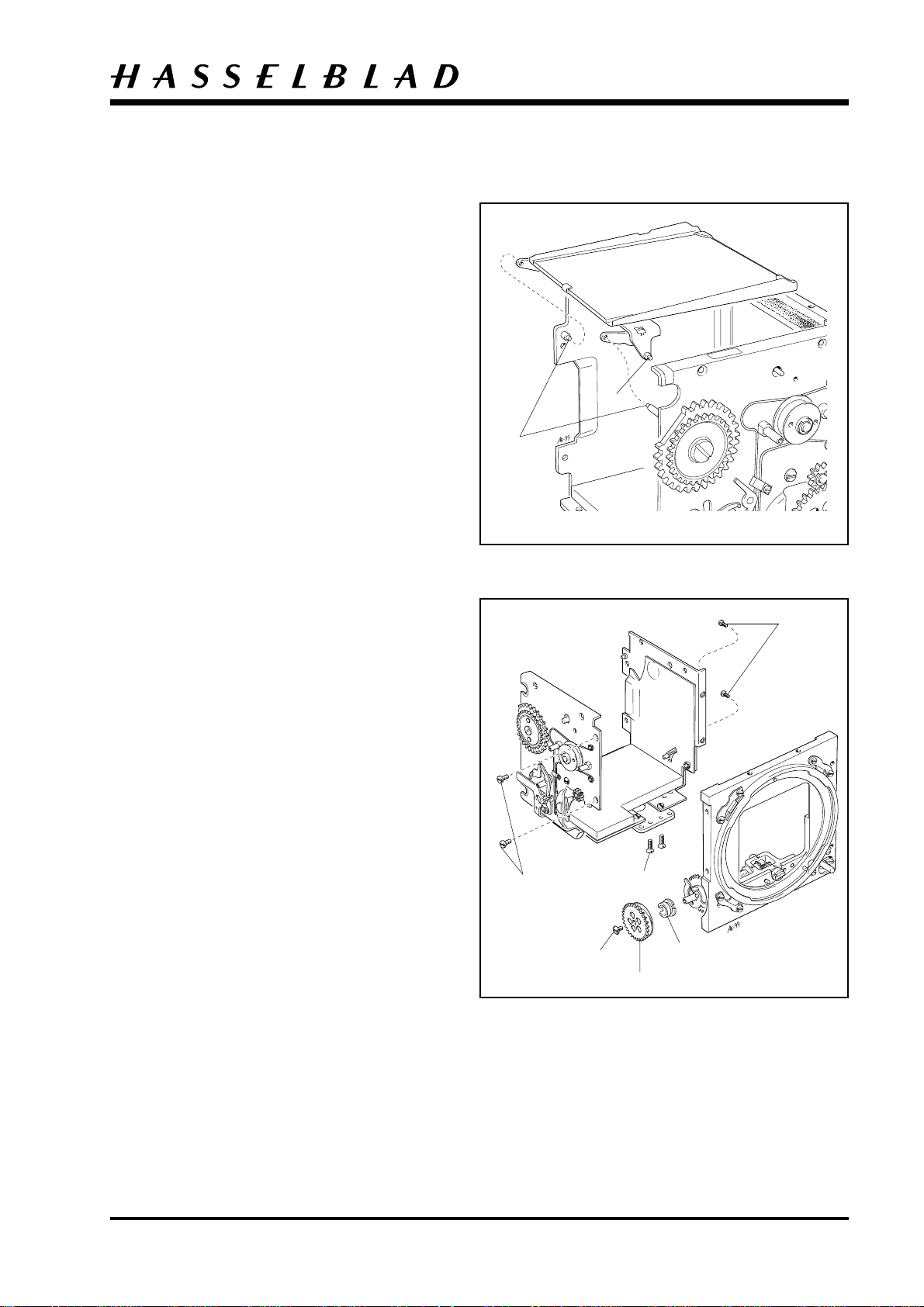
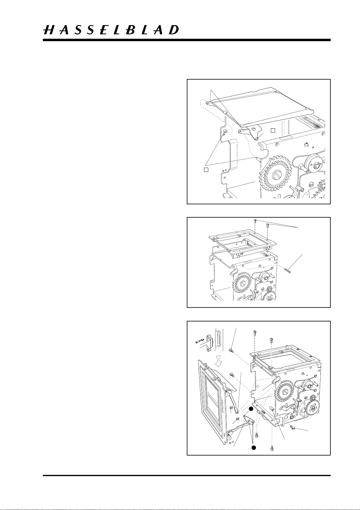
Right and left hand wall
Remove (or cut) the foam plastic pad (22513) to get
access to the screws (820014). remove the right hand
wall.
Fig. 15.
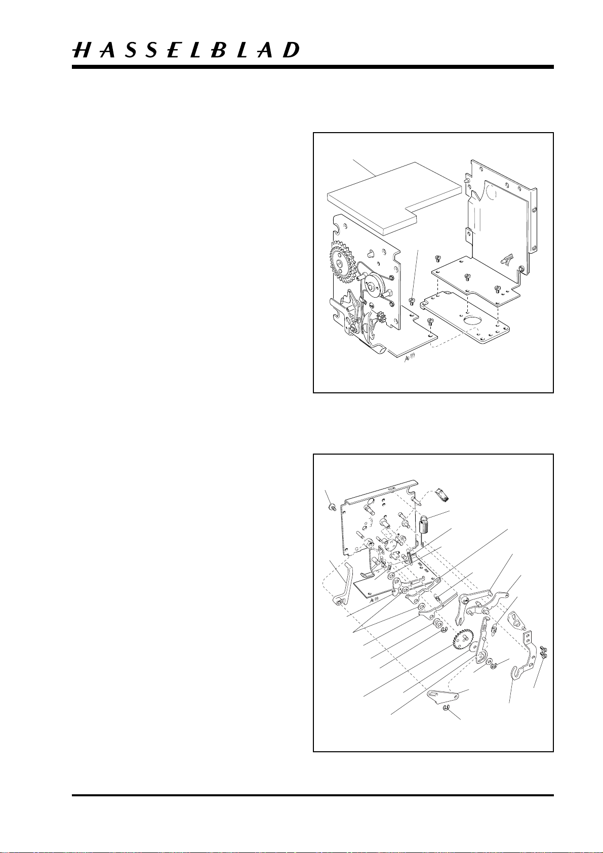
Mechanism plate
To dismantle the right and left hand wall proceed
using the following sequence:
Disassembly
22513
820014
Inner wall right
Remove the spring (814862). Remove the two screws
(820013) that secure the support (30701).
Remove the clip "A" (817115) and lift the plate
(22714).
Lift the arm (22896).
Remove the spring (814861), clip "B" (817115) and
washer (810532). Lift the mirror actuating arm
(22458) and the mirror lever (22460). Remove the
teflon washer (810761).
Remove the screw "C" (821033) that secures the gear
(22476) to the inside wall, then lift the gear clear.
Lift the auxiliary shutter arm (13554) clear.
Disconnect the springs "D", "E" and "F" (814302,
814706 and 814509).
Remove the clip (817123) and two washers (810702/
705). Lift the locking arm (21219) clear, together
with the washer (810702) underneath. Lift the S-arm
(22923) clear together with the washer (810702). Lift
the B-arm (21221) clear together with the washer
(810703).
Fig.16.
DIS17.EPS
990505
"C"
22896
21221
810702
21219
810702/705
22476
"D"
817123
22458
810761
814862
"E"
810703
810532
"A"
"F"
22714
Fig.15
22923
13554
22460
814861
"B"
820013
30701
Fig. 16
Revision 0
May 1999
3:8
Camera body 555ELD
Outer wall right
Remove the screw (821012) and lift the gear (13558)
clear, together with the washer (810854).
Remove the clip "A" (817119) from the inside wall.
The release arm (22922) can now be lifted clear of
the outside wall.
Remove the clip (817112) from the inside wall.
The release catch (13570) and the torsion spring
(816608) underneath can be lifted clear of the outside
wall. Remove the draw spring (814309) that connects
the release lever (30793) to the stop (22317).
Remove the clip "B" (817115) and washer (810538),
then lift the release lever clear. Remove the clip "C"
(817119) and lift the gear (13567) clear, together
with the dog (13525).
Remove the clip (817123), the washer (810702/705)
and the selector (13559). Remove the screw
(820011) and cable holder (12453).
Remove the two clips "D" (817115), then remove the
S-wire (21223) and the A-wire (21224).
Fig. 17.
821012
810702/705
817123
22922
13570
816608
DIS19.EPS
990316
13558
"B"
13559
810538
"C"
820011
30793
13567
810854
814309
Disassembly
"D"
21223
"A"
817112
"D"
22317
12453
21224
13525
Fig. 17
The dismantling procedure for the Hasselblad
555ELD is now completed.
Revision 0
May 1999
4:1
Camera body 555ELD
Lubricate the camera as detailed in the appropriate
lubrication chart. Use the lubricants listed below:
= Isoflex Topas L32
= Mollykote - X
= Isoflex PDP-48
= Gleitmo 805-K
= Loctite, e.g. Loctite 243
= Safety lacquer
Mechanism plate
To reassembly the right and left hand walls
proceed using the following sequence:
Outer wall right
DIS19.EPS
990316
Reassembly
Fig. 18
Lubricate according to Fig. 18.
Locate the A-wire (21224) and the S-wire (21223)
and secure them into place with the two clips "D"
(817115).
Fit the cable holder (12453) over the A and Swires and fit the screw (820011). Fit the selector
(13559) and secure it into position with the
washer (810702/705) and the clip (817123).
Fit the release lever (30793) and secure it into
position with the clip "B" (817115) and washer
(810538). Refit the draw spring (814309) securing
both ends of the spring.
Fit the torsion spring (816608) and the release
catch (13570) and secure them into position using
clip (817112). Note: This clip is fitted on the
inside wall.
Fit the release arm (22922) and secure it with the
clip (817119) which clips on from the inside wall.
Fit the gear (13558) and washer (810854) and then
fit the screw (821012).
Fig. 19.
821012
810702/705
817123
22922
13570
816608
DIS19.EPS
990316
"B"
13558
13559
810538
820011
814309
30793
810854
"D"
21223
817119
817112
"D"
12453
21224
Fig. 19
Revision 0
May 1999
DIS18.EPS
990316
4:2
DIS18.EPS
990316
Camera body 555ELD
Outer wall right
Lubricate according to Fig. 20.
Fit the washer (810703) followed by the B-arm
(21221), then fit the washer (810702) followed by
the S-arm (22923).
Fit the washer (810702) followed by the locking arm
(21219) and the two washers (810702/705) and
secure them into place with the clip (817123).
Fit the auxiliary shutter arm (13554).
Reassembly
Fit the gear (22476) and secure it into position with
the screw "C" (821031) from the outside wall.
Check the function.
Fit the mirror lever (22460).
Fit the teflon washer (810761) on the top of gear
(22476).
Fit the mirror actuating arm (22458) followed by the
washer (810532) and secure with the clip "B"
(817115).
Fit the arm (22896) and the plate (22714). Secure
them into position with the clip "A" (817115).
Check for easy of operation.
Fit the support (30701) and secure it in position
with the two screws (820013).
Fit the spring (814862).
Fit the spring (814861).
Fit the spring "F" (814509).
Fit the spring "E"(814706).
Fit the spring "D" (814302) Note: Secure the spring
with safety lacquer.
Fig. 21.
"C"
22896
21221
810702
21219
810702/705
22476
"D"
817123
22458
810761
814862
"E"
810703
810532
"A"
"F"
22714
Fig. 20
22923
13554
22460
814861
"B"
820013
30701
Revision 0
Fig. 21
May 1999
4:3
Camera body 555ELD
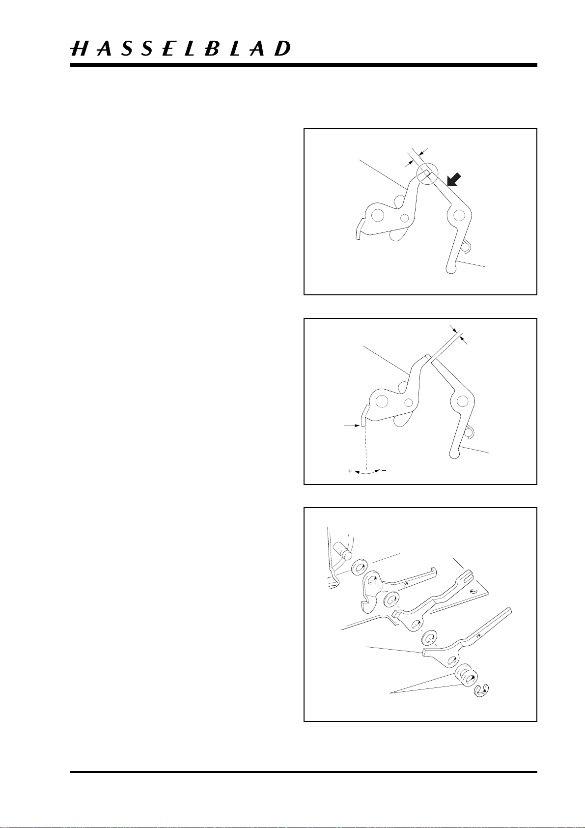
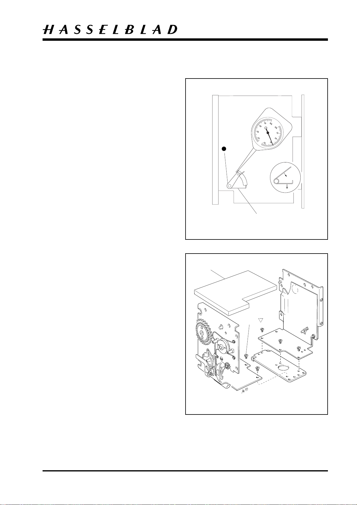
Release catch/arm adjustment
Check and if necessary bend the release catch (13570)
at the arrow so that it is engaged by approximately
1mm.
Fig. 22.
Refit the gearwheel (13557) temporarily. Rotate the
gear anticlockwise and check that the overtravel on
the release arm (22922) is approximately 1mm with
respect to the release catch (13570).
22922
REA02.EPS
990316
22922
Reassembly
13570
Fig. 22
If adjustment is required, bend the angle on the
release arm (22922) see arrow.
Fig. 23.
Locking arm adjustment
Check that the arms move easily without axial play.
If there is play on the locking arm (21219) then fit a
further washer (810702/705) in addition to the two
already fitted. If the arms are sluggish then try a
thinner washer.
Fig. 24.
REA03.EPS
990316
21219
13570
Fig. 23
Revision 0
810702/705
REA04.EPS
990316
Fig. 24
May 1999
4:4
Camera body 555ELD
Left hand wall
Check the tension of the spring (816864). This should
be between 40 and 60 grams.
Adjust by bending the spring (816864) as indicated in
Fig. 25.
REA05.EPS
990505
Reassembly
816864
Fit the left and right hand walls together and secure
with the screws (820014). Fit the foam plastic pad
(22513).
Fig. 26.
Fig. 25
22513
820014
Revision 0
DIS17.EPS
990505
Fig. 26
May 1999
DIS16.EPS
990505
4:5
Camera body 555ELD
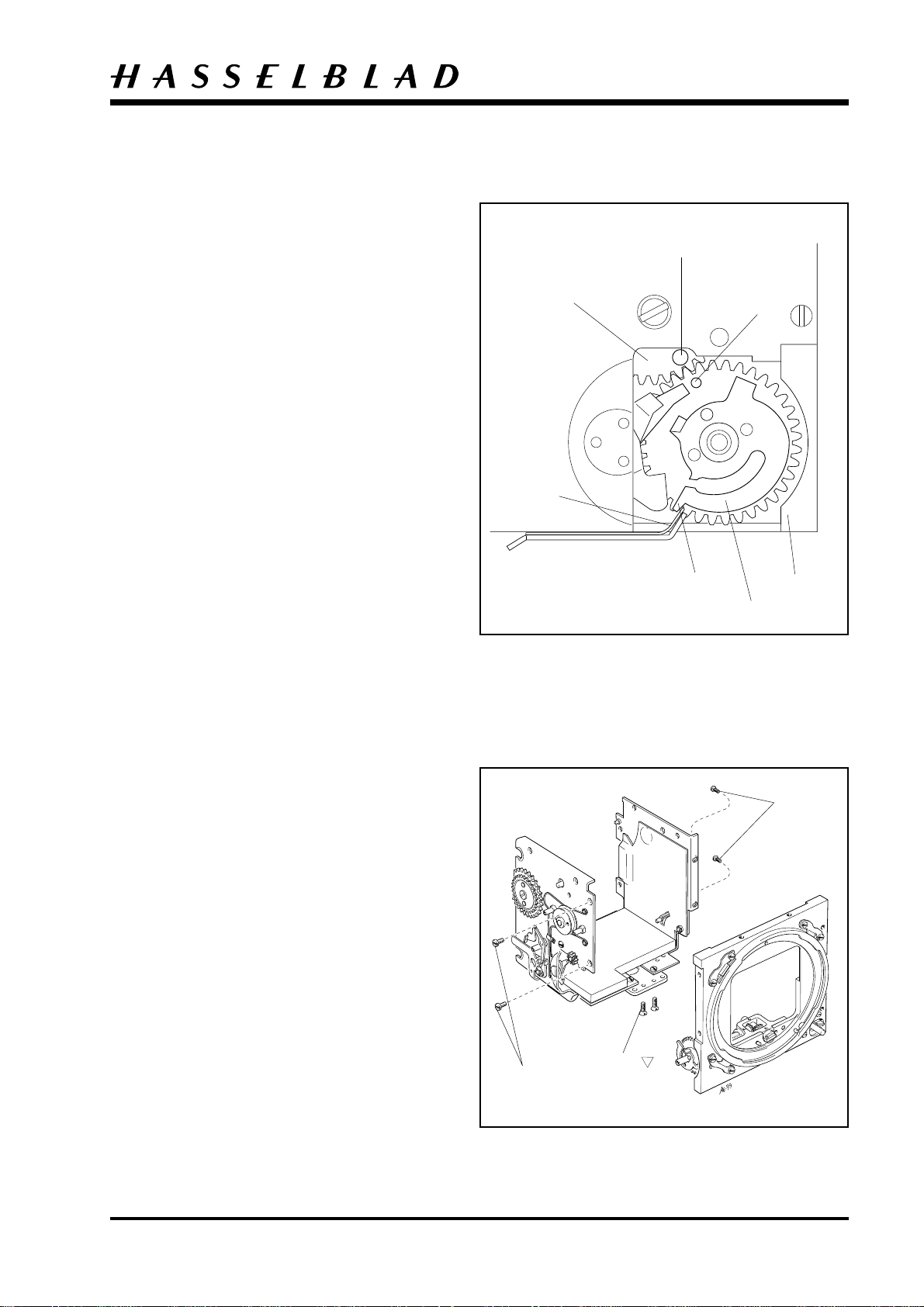
Front bayonet plate
Before fitting the bayonet plate (30706-1) make sure
the camera is released. This is done by turning gear
(22476). Note that the pin "A" should be visible from
the outside.
Fig. 27.
Fitting the front bayonet plate to the camera body:
Tension the drive spring by turning the front gear
wheel (30413) clockwise 3 turns.
Fit in the lower part of the bayonet plate so that the
check "C" on the front gear cam plate is stopped by
the spring (22317). Ensure that the two indexes "A"
and "B" are aligned opposite each other and that the
upper part of the bayonet plate is put into position.
Fig. 27.
22476
22317
Reassembly
"A"
"B"
Secure the bayonet plate to the right hand wall using
two screws (823015). Secure the bayonet plate to the
REA06.EPS
990316
bottom of the main camera body using two screws
(823655). Refit the two screws (820015) to the rear
of the bayonet plate.
Fig. 28.
"C"
30706-1
30413
Fig. 27
820015
Revision 0
823015
823655
Fig. 28
May 1999
4:6
Camera body 555ELD
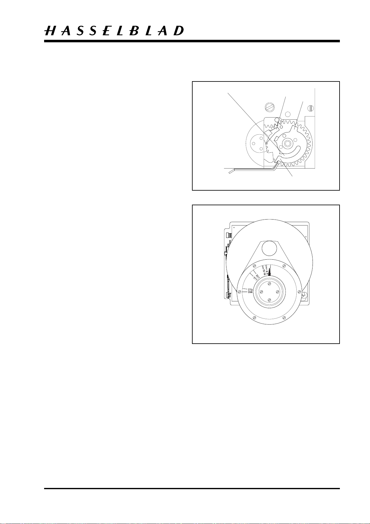
The key position of the front gear is checked with the
camera cocked. This is carried out as follows:
Fit the blade of a screwdriver in the slot on the front
gear wheel (30413). Turn the gear in a clockwise
direction until the check "C" has passed the locking
arm (21219). In this position it is now possible to
cock the release arm (22922) against the release catch
(13570). Continue the cocking action until the
locking arm (21219) operates and is blocked against
the check "D".
Fig. 29.
Mount the key inspection tool 902658 (V-2075) to
the camera's front bayonet plate. Ensure the indicator
is pointing upwards when the camera is cocked.
Fig. 30.
With the tool 902658 (V-2075) fitted to the front of
the camera, the key position should have a minimum
of 3º with a load of 1400 gram-centimetres and a
maximum of 9º with 300 gram-centimetres. Remove
the tool.
Fig. 30.
Position for screw driver
REA06.EPS
990316
Reassembly
21219
"D"
"C"
Fig. 29
1. If the measured value is less than 3º, replace the
ordinary locking arm (21219-2) by a locking arm
which is 0.2 mm longer. This arm is designated
(21219-1).
2. If the measured value is more than 9º, replace the
ordinary locking arm (21219-2) by a locking arm
which is 0.2 mm shorter. This arm is designated
(21219-3).
3. If the above-mentioned adjustment is insufficient,
a new front gear (30413) must be fitted on the
bayonet plate.
REA07.EPS
990316
Fig. 30
Revision 0
May 1999
4:7
Camera body 555ELD
Mirror
Lubricate according to Fig. 31.
Make sure the camera is released. Locate the mirror
(30716) into position. Connect the mirror hinge
(30754) to the two pins "A".
Relocate the pin "B" on the mirror frame to the
mirror lever (22460).
Fig. 31.
Test the function of the mirror by fitting the blade of
a screwdriver in the slot on the front gear wheel and
cock the camera. Release by moving the release catch
(13570) to the rear.
Fig. 29
Focusing screen frame
30754
"A"
DIS15.EPS
990316
Reassembly
"B"
Fig. 31
Refit the focusing screen frame and secure it as
follows:
Refit the two long screws (823028) to the right hand
side wall and two short screws (821017) to the top of
the frame.
Fig. 32.
Rear plate
Fit the springs (815511) to the screws (105412).
Fit the contact flex (22915) to the rear plate and
secure it into position with the above mentioned
screws.
Lubricate according to Fig. 33.
Release the camera. Fit in the actuating part (13551)
and secure it in the position with the clip "C"
(817115).
Locate the upper actuating part (13580) around the
pin "D" and fasten it to actuating part (13551).
Secure it in position with the clip "E" (817115).
DIS14.EPS
990316
821017
823028
Fig. 32
820013 (short)
13580
"D"
Locate the spacer (13547). Note: Turn the front gear
(30413) somewhat in a clockwise direction.
Locate the rear plate into position and secure it with
seven screws, note the long screw (820025) is fitted
on the right hand wall and the short one (820013) at
the top of the left hand wall.
Fig. 33.
Revision 0
REA21.EPS
990505
"E"
"C"
13551
820025
13547
Fig. 33
May 1999
4:8
Camera body 555ELD
Seal between the rear plate and the left side wall
using black silicone or similar as shown in Fig. 34
to ensure a tight light seal.
Preliminary adjustment of the focal length
REA09.EPS
990316
Reassembly
Seal here
Fig. 34
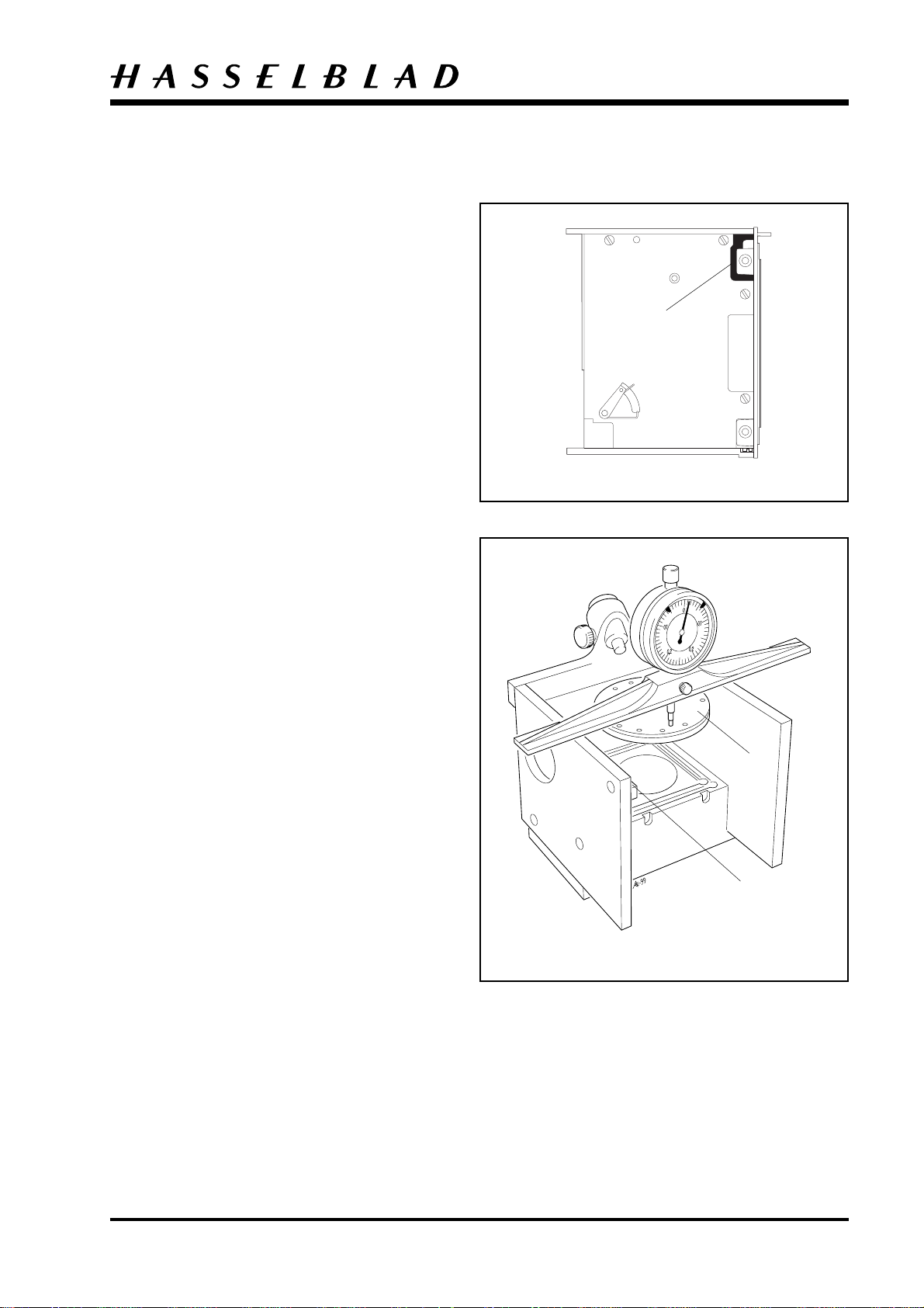
71.40 ± 0.03 mm
Mount the front plate "A" in the front of the camera
body and place the camera with the rear section in
control tool V-2229.
Check that the rear section is flat.
If the rear section is warped, the first procedure is to
ensure that both the inner walls of the camera are in
good contact with the inside of the rear section. This
is carried out by knocking carefully on the front plate
with a plastic-faced hammer.
If this operation is insufficient, it is possible to adjust
the warp at the corners which may be too low.
Loosen the two nearest screws and push the rear
section backwards until it is flat. Then tighten the
screws.
Place the camera body in control tool V-2229
without tensioning it. Set the ruler with the indicator
clock to zero by placing it on surface "B".
Fig. 35.
"A"
"B"
REA14.EPS
990316
Fig. 35
Revision 0
May 1999
4:9
Camera body 555ELD
Place the ruler with indicator clock onto the gauge
and move the indicator around the periphery on the
front plate and check that the length is within the
tolerance.
If the camera body is too short, on the left-hand side,
then the front must be moved forward on this side.
This is carried out by knocking on the angle on the
left wall which provides the support for the bayonet
plate. A solid fibre rod and a suitable hammer are
used for this operation.
Re-check as described above.
If the camera is too short on the right hand side, it
must extended. This is carried out by moving the rear
section to the rear. Loosen the screw (820025) on the
right wall (30748), the screw (820015) on the bottom
of the camera and the screw (820017) on top of the
camera. Insert the blade of the screwdriver first in one
and then in the other of the two rectangular recesses
in the rear edge of the right wall close to the rear
section and turn carefully. Then tighten the screws
and check on control tool V-2229 that the rear
section has not become distorted during adjustment.
Fig. 36.
Reassembly
Check the length measurement above.
If the total length measurement of the camera body is
too long, adjust the bayonet front plate downwards
by knocking on the front plate "A" at the points
where necessary.
Re-tighten all screws retaining the rear section, the
front plate and the frame.
Note! The focal length is checked once more when
the camera is fully reassembled.
REA20A.EPS
990505
Adjust here
Fig. 36
Revision 0
May 1999
REA20.EPS
990505
REA06.EPS
990316
4:10
Camera body 555ELD
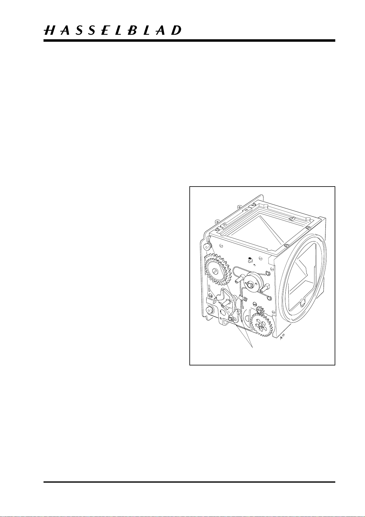
Dog (13525), gear (13567) and gear
(13556)
Cock the camera as follows:
Fit the blade of a screwdriver in the curved slot on
the front gear (30413). Turn the gear in a clockwise
direction until the check "C" has passed the locking
arm (21219). In this position it is now possible to
cock the release arm (22922) against the release catch
(13570). Continue the cocking action until the
locking arm (21219) operates and stops against the
check "D".
Fig. 37.
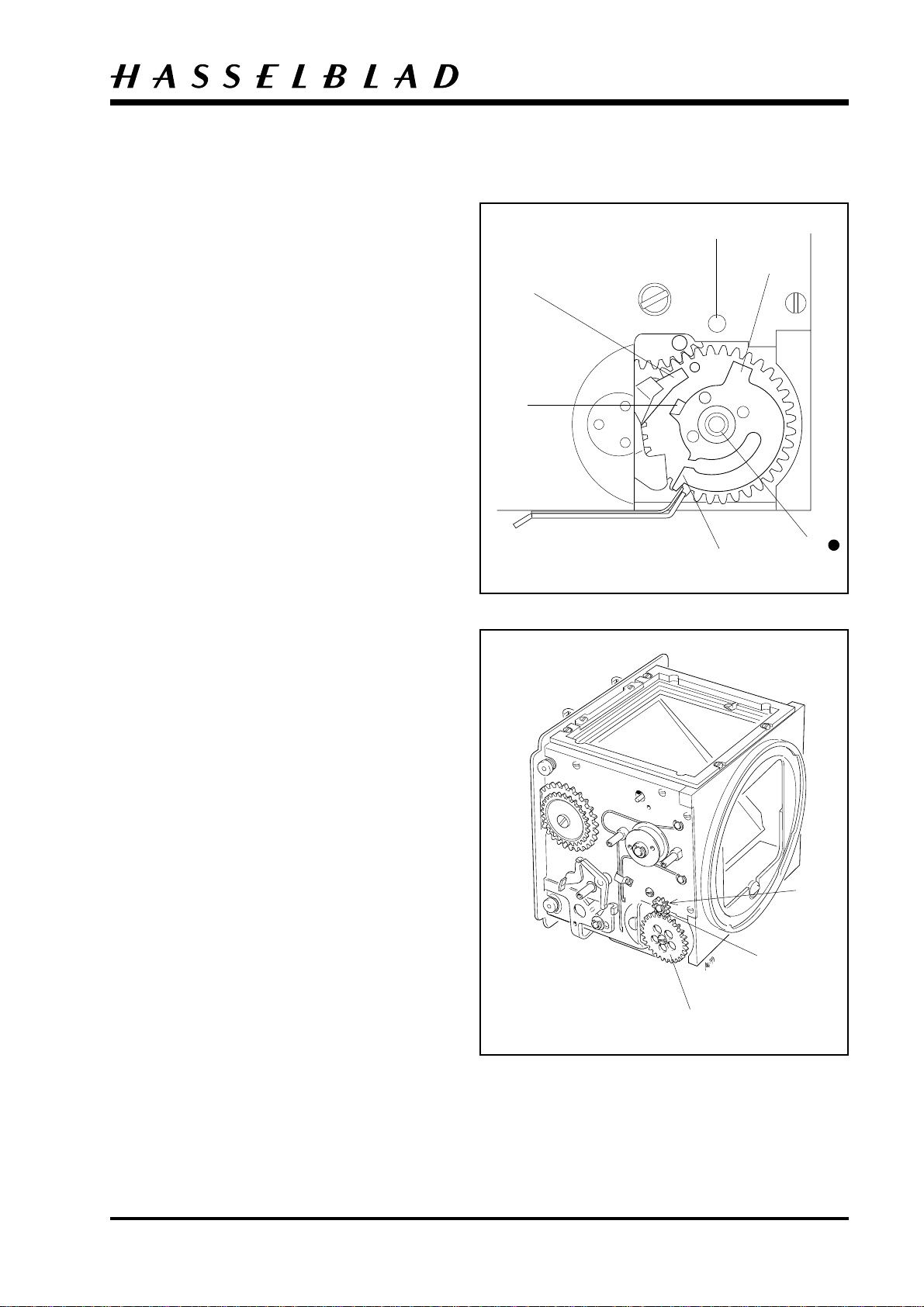
Lubricate the front gear journal "F". Locate the dog
(13525) onto the pin "E" with the bent lug upwards.
Place the disk (21324) with the large flange
downwards on the front gear journal. The recess in
the disk fits against the pin on the front gear cam
disk.
Check that both catches on the gear (13556) move
easily and that the spring-loaded setting hook returns
under the influence of its own spring. If the
movement of the catches should be doubtful, this can
possibly be adjusted by carefully bending the ring
which is riveted on.
Reassembly
"E"
"D"
21219
"G"
"F"
"C"
Fig. 37
The gear (13556) is fitted so that the point of the
hook which is not spring-loaded comes into contact
with the recess in the disk (21324). Turn the gear in a
clockwise direction until the spring-loaded setting
hook stops against the check "G" as shown in Fig. 37.
The dog (13525) is backed off in an anti-clockwise
direction so that the bent lug rests against the
periphery of the spring-loaded setting hook in gear
(13556).
Fit gear (13567) with the pin pointing downwards
from "E".
Fig. 37.
Note that the gear (13556) and the dog (13525) must
be retained in the positions previously described. This
facilitates adjustment. Ensure that the pin on gear
(13567) is placed in the hole on the dog (13525) in a
12 o'clock position.
Fig. 38.
13525
13567
13556
Fig. 38
Revision 0
May 1999
4:11
Camera body 555ELD
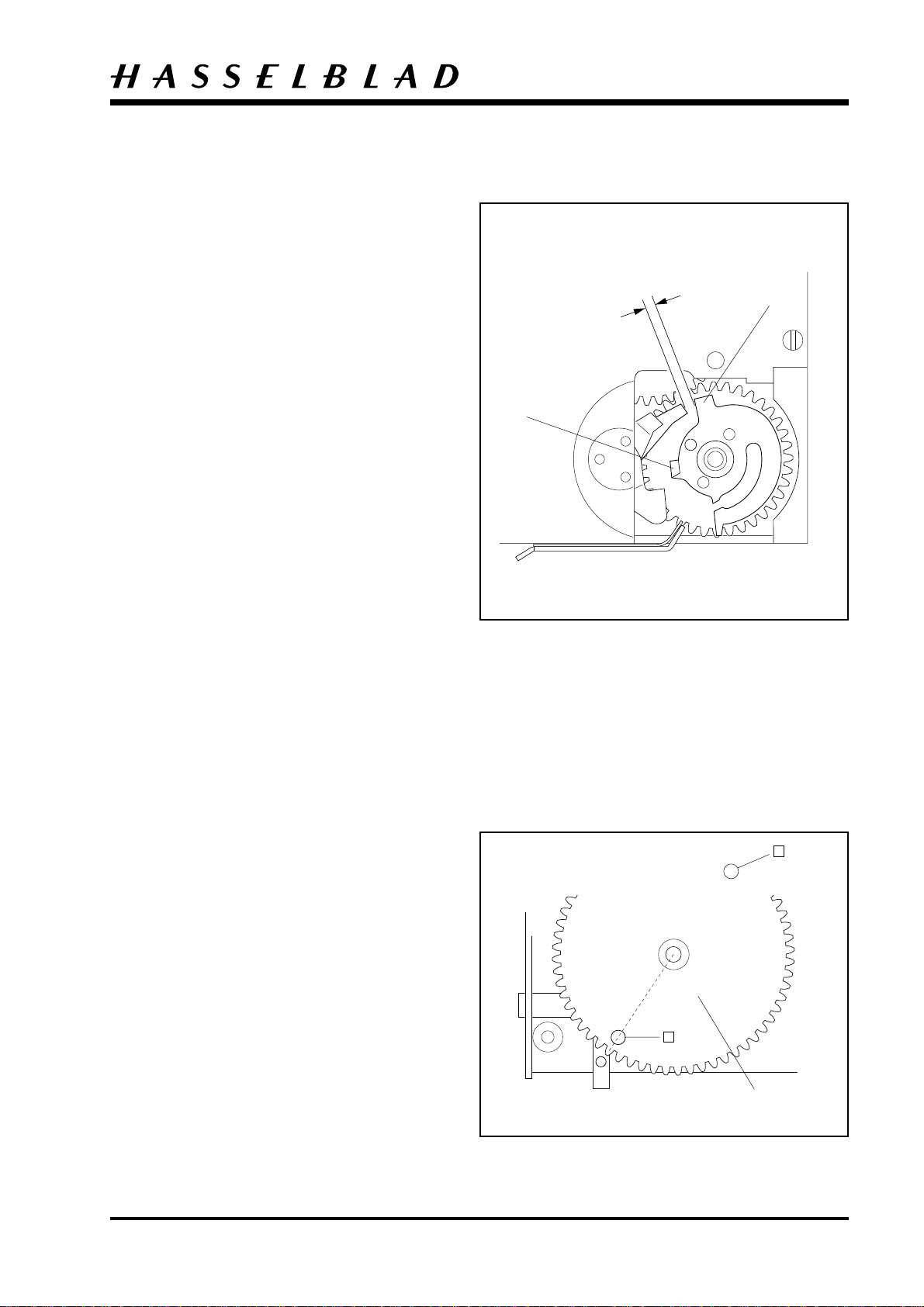
When the gear (13556) is turned in a clockwise
direction the dog (13525) should release the setting
hook from the check "G".
Fig. 39.
Adjustment: Disengagement should occur when the
check "D" has passed the locking arm (21219) and
moved a further 1 - 2 mm. (this is a safety margin to
ensure that the lens is fully cocked).
Fig. 39.
If a further movement is needed, then the
relationship between the dog (13525) and the gear
(13567) must be altered.
Adjustment: If smaller movement is required, lift the
gear (13567) out of engagement with gear (13556).
Turn gear (13567) one (1) tooth segment in an anticlockwise direction. Re-check as specified above.
Reassembly
1 - 2mm
"D"
"G"
Adjustment: In the case of excessively large further
movement, carry out the same operation in the
reverse direction.
Tighten gear (13556) with screw (821033) and secure
gear (13567) with clip (817119).
Note that the front gear (30413) must be held when
the screw for gear (13556) is tightened. This can be
done in a convenient way by inserting the blade of a
screwdriver on the underside of the camera between
the spring stop (22317) and the fixed gear on the
front gear.
Gear (13557)
The initial position for fitting gear (13557) is as
follows. The dog (13525) has just operated the springloaded setting hook on gear (13556) and further
movement has been checked as described previously.
Gear (13556) is backed in an anti-clockwise direction
until the spring-loaded setting hook stops against the
upper point "G" on the front cam disk.
Fig. 39.
REA10.EPS
990316
Fig. 39
The straight side of gear (13558) is placed parallel
with the rear section of the camera. Lubricate and fit
the gear wheel (13557) on its pin. The position of
both the pins on the underside of the gear is shown in
Fig. 40.
Tighten gear (13557) with one screw (821033).
Revision 0
REA11.EPS
990316
13557
Fig. 40
May 1999
 Loading...