

Page 1
HARTING
04 2E
Solutions for Industrial Ethernet
Page 2

HARTING was founded in 1945 by
the family that still owns the company.
Today, HARTING employs around
2,300 people worldwide, including
150 qualified engineers. The sales
team, including more than 100 sales
engineers is in daily contact with our
customers.
The company is one of the world’s
leading manufacturers of connectors,
and currently have 33 subsidiary
companies in Europe, the United States
and Asia. In several product ares,
HARTING is a market leader.
Great emphasis is placed on close links
with customers, including the provision
of a ‘Just-in-Time’-Service to ensure
rapid delivery to key customers.
HARTING products are designed and
manufactured using the latest
automated techniques, from CAD
systems in the research and
development department to automatic
production techniques on the assembly
lines.
Production and quality control is based
on a ‘zero-error’ philosophy which can
only be reached by the continuous
successful implementation of fully
automated production techniques.
The organisation and procedures for
quality assurance are based on the
EN ISO 9001 standard. A total of
60 engineers and other employees,
most of whom are trained and qualified
to standards laid down by the DGQ
(German Association of Quality) or the
SAQ (Swiss Association of Quality), are
employed solely on quality-assurance
activities.
Quality Connections
Worldwide
People | Power | Partnership
Page 3
00
.
01
Chapter
Directory
Solutions for Industrial Ethernet
Industrial Ethernet – General information 00
Connectors 02
Active and passive
network components
01
System cables 03
List of part numbers 10
Company addresses 20
Page 4

00
.
02
Solutions for Industrial Ethernet
General information
It is the user's responsibility to check
whether the components illustrated in
this catalogue comply with different
regulations from those stated in special
fields of application which we are unable
to foresee.
We reserve the right to modify designs
in order to improve quality, keep pace
with technological advancement or meet
particular requirements in production.
This catalogue must not be used in any
form or manner without our prior
approval in writing (Copyright Law,
Fair Trading Law, Civil Code).
We are bound by the German version
only.
General
information
Page 5

00
.
03
What is Ethernet?
. . . . . . . . . . . . . . . . . . . . . . . . . . . . . . . . . . . . . . . . . . . . 00.04
Ethernet principles
Classic Ethernet . . . . . . . . . . . . . . . . . . . . . . . . . . . . . . . . . . . . . . . . . . . . . 00.04
Ethernet transmission media in common use . . . . . . . . . . . . . . . . . . . . . . 00.04
Fast Ethernet . . . . . . . . . . . . . . . . . . . . . . . . . . . . . . . . . . . . . . . . . . . . . . . 00.05
Switched Ethernet . . . . . . . . . . . . . . . . . . . . . . . . . . . . . . . . . . . . . . . . . . . 00.05
The Industrial Ethernet network
General requirements for Industrial Ethernet networks . . . . . . . . . . . . . . . 00.08
PROFInet
®
transmission system and wiring . . . . . . . . . . . . . . . . . . . . . . . 00.09
Glossary
. . . . . . . . . . . . . . . . . . . . . . . . . . . . . . . . . . . . . . . . . . . . . . . . . . . . 00.12
Industrial Ethernet – General information
Page
Directory chapter 00
General
information
Page 6

00
.
04
Industrial Ethernet – General information
What is Ethernet?
Ethernet is a well established specification for serial
data transmission, originally published by Xerox in
1975. In 1985 Ethernet was standardised in IEEE
802.3, since when it has been extended a number of
times. "Classic" Ethernet operates at a data transmission rate of 10 Mbit/s.
Since the 1990s, Ethernet has developed in the
following areas:
– Transmission media
– Data transmission rates
l
Fast Ethernet at 100 Mbit/s (1995)
l
Gigabit Ethernet at 1 Gbit/s (1999)
l
There are plans for Ethernet running at 10 gigabits
– Networked topologies
l
Switched Ethernet
– Industrial Ethernet
Nowadays Ethernet is the most widespread base
technology in the world in commercial DP systems,
and is also gaining importance in industrial automation. The use of Ethernet creates a homogenous
and standardised communication infrastructure,
extending seamlessly from the office environment to
the machine.
Classic Ethernet (Shared Ethernet)
All network users have the same rights under Ethernet.
Any user can exchange data of any size with another
user at any time.
Because Ethernet was conceived as a logical bus system, any network device that is transmitting is heard by
all other users. Each Ethernet user filters the data
packets that are intended for it out from the stream, ignoring all the others.Telegrams that are intended for all
devices are an exception to this rule.These are known
as broadcast or multicast telegrams.
The CSMA/CD network access procedure
In Classic Ethernet, also frequently called shared
Ethernet, all the network users share one collision
domain. In Ethernet, network access is controlled by
the CSMA/CD procedure (Carrier Sense Multiple
Access with Collision Detection).
If a network user wishes to transmit data, it first checks
whether the network is free (carrier sense). If so, it
starts to transmit data. At the same time it checks
whether other users have also begun to transmit
(collision detection). If that is the case, a collision
occurs. All the network users concerned now stop their
transmission, wait for a period of time determined
according to a randomising principle, and then start
transmission again.
The result of this is that the time required to transmit
data packets depends heavily on the network loading,
and cannot be determined in advance. The more
collisions occur, the "slower" the entire network
becomes. Shared Ethernet therefore only has limited
suitability for industrial automation.
The physical size of the network is also limited. It
depends on the data rate being used and on the
maximum permissible transmission time of data
packets.
Approaches to improved performance
A number of approaches have been tried to improve
performance:
Segmentation: -> subdividing the collision domains
Higher
bandwidths: -> Fast Ethernet, Gigabit Ethernet
Switching: -> Switched Ethernet
and combinations of these.
Only with the implementation of these approaches
does Ethernet become interesting and useful for
industrial automation. For this reason, only Switched
Ethernet and Fast Ethernet will be considered further
in the following chapters.
Ethernet installations are primarily characterised by
two parameters: the Category of the cable (Category)
and the Class of the channel (Class).
General
information
Ethernet transmission media in common use
Description Meaning Distance
10 Mbit/s system
10 Base T [FD] 2 conductor pairs, min. Category 3, UTP and STP >100 m
10 Base FX [FD] Fibre-optic cable Depends on fibre type
100 Mbit/s system (Fast Ethernet)
100 Base TX [FD] 2 conductor pairs, Category 5, UTP and STP 100 m
100 Base FX [FD] Fibre-optic cable Depends on fibre type
[FD] = Full-duplex operation possible
Page 7
00
.
05
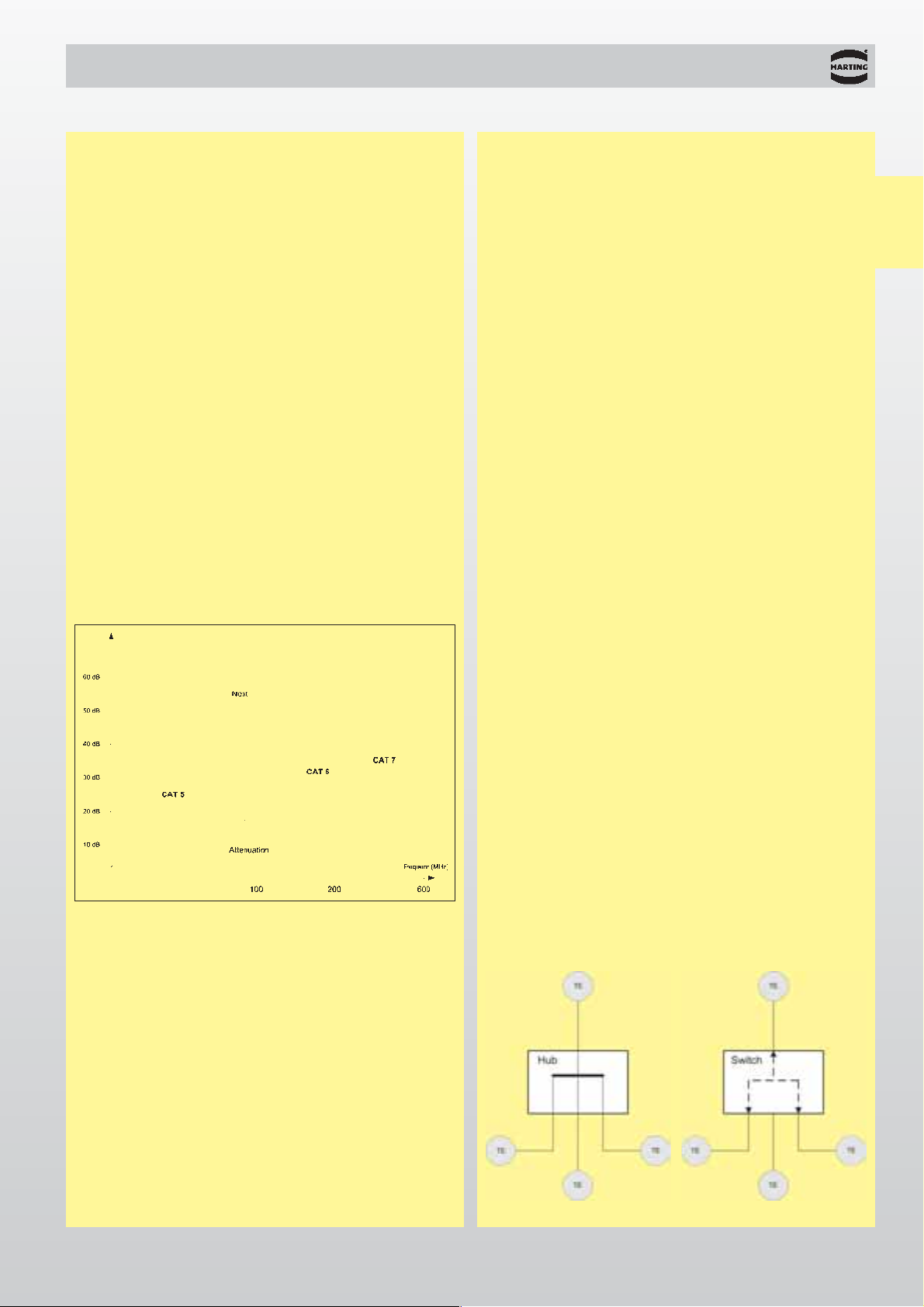
Next = Near end crosstalk
Industrial Ethernet – General information
The cable is identified by its Category in accordance
with its electrical transmission and high-frequency
properties, as follows:
Category 1: not specified
Category 2: up to 1 MHz
Category 3: up to 16 MHz
Category 4: up to 20 MHz
Category 5: up to 100 MHz
Category 6: up to 250 MHz
Category 7: up to 600 MHz
The channel is the point-to-point part of the transmission process, and is specified as follows:
Class A: up to 100 kHz
Class B: up to 1 MHz
Class C: up to 16 MHz
Class D: up to 100 MHz
Class E: up to 250 MHz
Class F: up to 600 MHz
The higher the alphabetical sequence of the letter, the
tougher are the requirements on the transmission
channel, and therefore also on the cable. If, for
instance, only Category 5 components are used in a
system, the capacity of a Class D cable is required.
The same applies to Category 6 and Class E, as to
Category 7 and Class F.
General
information
TE = Terminal Equipment
Switched Ethernet
Definition
Switched Ethernet refers to a network in which each
Ethernet user is assigned a port in a switch.
Switches separate former collision domains into
individual point-to-point connections between the
network components and the relevant user equipment.
Preventing collisions makes the full network bandwidth
available to each point-to-point connection. The second
pair of conductors in the Ethernet cable, which otherwise is necessary for the detection of collisions, can
now be used as an additional transmission medium, so
providing a significant increase in data transfer rate.
The use of switches allows any desired network
configuration, such as star, ring, tree or linear, to be
implemented.
Switched Ethernet offers the following important
advantages:
l
The possibility of scaling the collision regions to
match the needs of the application, going as far as
fully collision-free networks in which only one user is
assigned to each port
l
Very fast packet transfer between the collision
regions
l
A considerable increase in data transfer rate through
"true" full duplex operation
l
Preventing collisions allows deterministic operation
Network size
There is no theoretical limit to the physical extent of a
Switched Ethernet network. The maximum length of
conductor between the ends of a point-to-point
connection is only determined by the physical
transmission properties and is, according to the
specification, 100 m. In practice, the connectors and
cables used have a decisive effect on the transmission
length that can actually be achieved.
Fast Ethernet
Fast Ethernet, according to IEEE 802.3, is not a new
standard, but an extension of Classic Ethernet to
include the following new properties:
l
A data rate of 100 Mbit/s
l
Switching
l
Full duplex operation
These form the basis of industrially useful Ethernet
networks. Autonegotiation provides compatibility with
Classic Ethernet in accordance with IEEE 802.3.
Page 8
00
.
06
Industrial Ethernet – General information
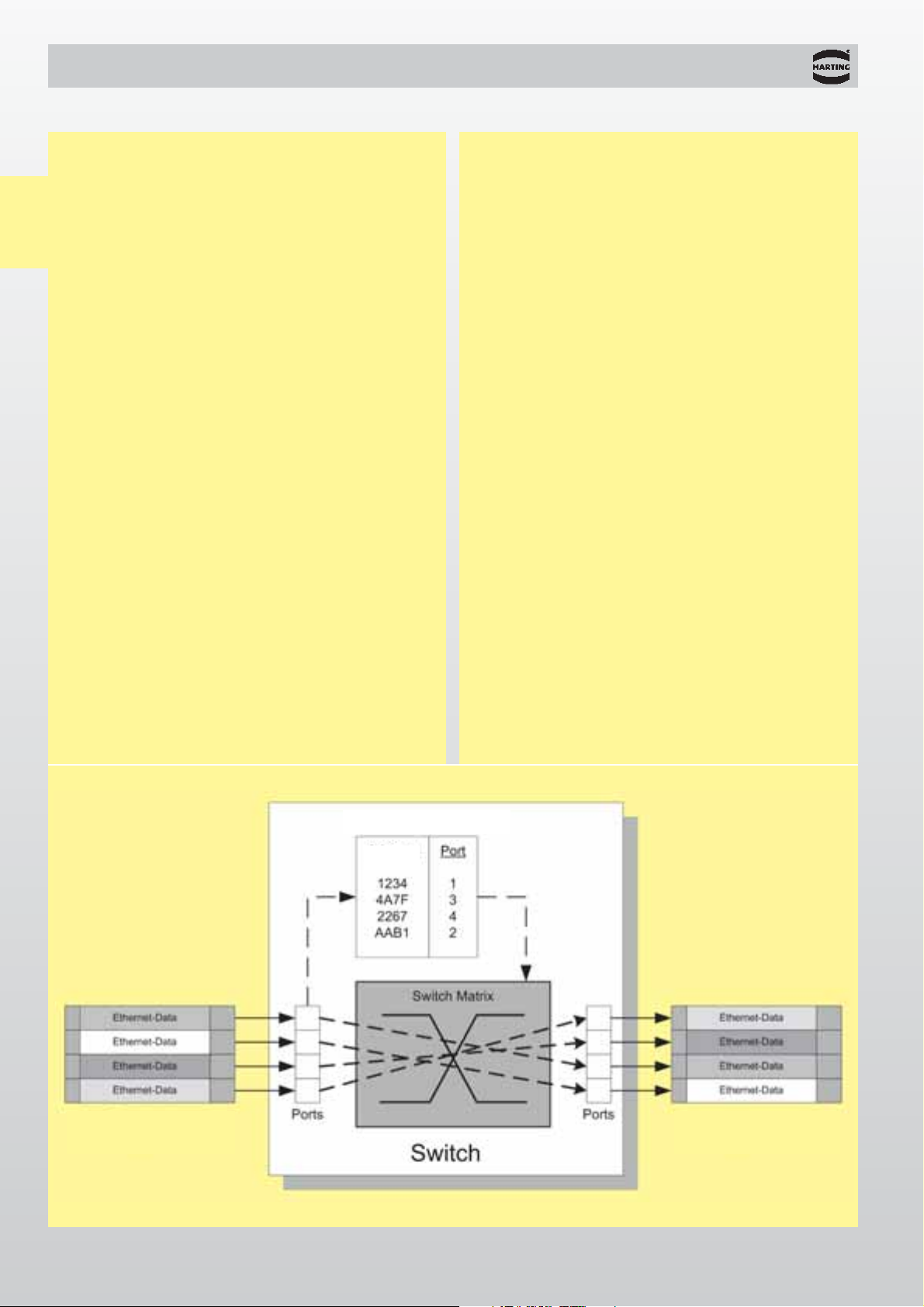
The switch – the central network
component in Switched Ethernet
Switches are active infrastructure components that
operate according to IEEE 801.3 on layer 2 of the OSI
reference model. Switches analyse all the data
packets as they arrive, directing them on to the port
where the corresponding user is located. Only multicast and broadcast telegrams are an exception to
this. They are passed on to all the active ports and
switches.
Each switch requires an address/port assignment
table in order to correctly redirect the telegrams. The
assignment of a destination address to a specific port
in the switch is stored in this table. The destination
address of an incoming data packet is analysed with
the aid of this table, and the data packet is passed on
immediately to the corresponding port. The
address/port assignment table is usually generated
and maintained automatically by the switch in a selflearning process. One switch can learn several
thousand addresses. This is necessary when more
than one item of user equipment is connected to one
or more ports. This allows a number of independent
subnets to be connected to one switch.
In this way, each of the ports in a switch generates its
own collision region. This prevents data collision with
users attached through other ports. In Switched
Ethernet, only one user is assigned to any port. In this
way collisions are avoided altogether. Guaranteed
freedom from collisions provides a significant
increase in the effective data transfer rate. Additional-
ly, full duplex operation is now possible, since one pair
of conductors in the Ethernet cable, otherwise
required to detect collisions, can be used as an
additional data transfer medium. With Fast Ethernet
operating in full duplex mode (100 Base TX), 100
Mbit/s can be transferred simultaneously in the two
directions.This corresponds to doubling the data rate.
Thanks to the switching technology it is possible to
construct Industrial Ethernet networks that satisfy the
requirements both for reliability and for real-time
performance.
Different types of switches
Switches are chiefly distinguished according to the
following features:
Modes of operation: Store and forward
Cut-through
Modified cut-through
Blocking: Blocking
Non-blocking
Management: Managed
Unmanaged
Principle of a switch
Incoming
telegrams
Outgoing
telegrams
Assignment table
General
information
Address
Page 9
00
.
07
Industrial Ethernet – General information
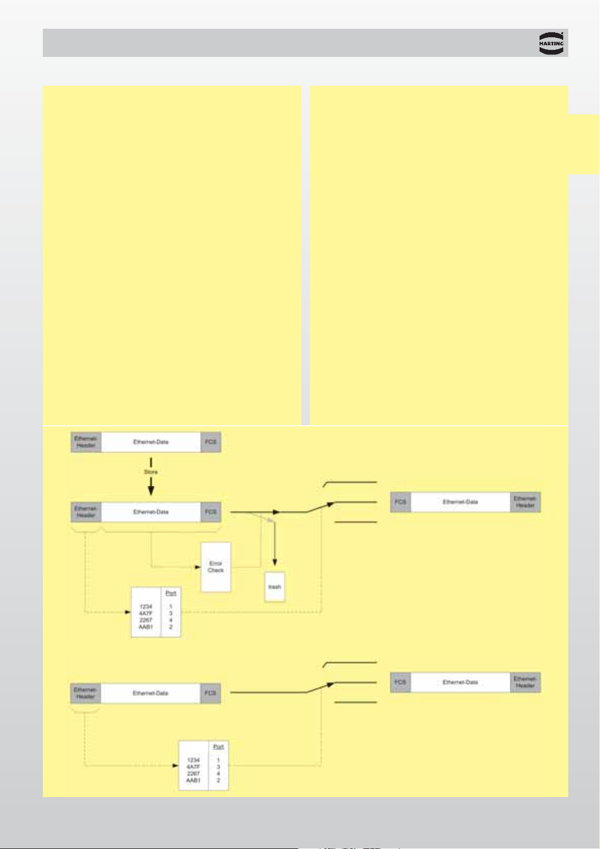
A comparison of the operating modes
Store and forward (Figure 1)
In this mode of operation, the switch temporarily
stores the entire data packet, checks it for errors and,
if it is free of errors, passes it on to the appropriate
port.
Cut-through / Modified cut-through (Figure 2)
In this mode of operation only enough bytes from the
data packet are placed into temporary storage as are
necessary for the evaluation in the address/port
assignment table.
Once this has been done, all the incoming bytes from
the data packet are passed on immediately to the
corresponding port without any intermediate storage.
In modified cut-through, the switch waits for precisely
64 bytes before making a decision according to the
address/port assignment table.
Blocking
A switch has a certain number of ports available to
it, and these are connected through the switch matrix.
If the switch matrix is capable of handling all
the connections without delay at full data rate
immediately, then it is called a non-blocking switch. If
the number of simultaneous connections at full data
rate is limited, the switch is said to be blocking.
Management
An unmanaged switch handles all the data traffic on
the basis of the address/port assignment table. The
user has no options for manipulating this.
A managed switch controls the data flow in
accordance with certain parameters or rules. The
basis for this activity is provided by the switch
management software. Modern switches support
SNMP management and web-based management.
These provide a variety of options for manipulation by
the user. The capabilities of the management
software differ from one switch to another.
Time behaviour
In Switched Ethernet, all the uncertainties of time
that result from Ethernet's collision management
algorithm (CSMA/CD) are eliminated. If correctly
dimensioned, Switched Ethernet thus becomes a
deterministic system. For the purposes of industrial
automation it is necessary to select the switches and
to dimension the network in such a way that the
switches operate within their deterministic range
under all operating conditions.
General
information
Figure 1
Figure 2
Address
Address
Page 10

00
.
08
Industrial Ethernet – General information
The Industrial Ethernet network
General requirements for Industrial Ethernet
networks
The international standard ISO/IEC 11801 and its
European equivalent, EN 50173, define an
application-neutral standard form of information
networking for a building complex. The contents of the
two standards are largely identical. Both standards
assume that the buildings are used in a way similar to
an office, and aim to be neutral towards particular
applications. The specific requirements for Ethernet
networks in industrial environments, such as
l
equipment-specific cabling
l
individually adapted levels of networking for each
machine/plant
l
linear network structures
l
robust, industrial cables and connectors meeting
special requirements for EMC, temperature,
humidity, dust and vibration
are not considered in either of these standards.
General
information
Office areas Production and other industrial areas
Installation
conditions
Transmission
capacity
Environmental
requirements
l
Fixed basic installation in the building
l
Cables laid in false floor
l
Devices connected at workstation vary
frequently
l
Prefabricated connecting cables
l
Largely standard work places
(desk with PC, …)
l
Tree network structures
l
Wiring depends heavily on the equipment
l
Equipment-specific cabling
l
Connection points are rarely modified
l
Device connections may be assembled on
site
l
Each machine/plant requires individual
levels of networking
l
Linear or (redundant) ring network
structures are common
l
Large data packets (e.g. images)
l
Medium network availability
l
Transmission time on the scale of
seconds
l
Predominantly acyclic transmission
l
No isochronism
l
Moderate temperatures
l
Low dust levels
l
No humidity
l
Little shock or vibration
l
Low EMI exposure
l
Low mechanical hazard
l
Low UV radiation
l
Very little chemical hazard
l
Small data packets (measurement data)
l
Very high network availability
l
Transmission time on the scale of
microseconds
l
High proportion of cyclic transmission
l
Isochronism
l
Extreme temperatures
l
High dust levels
l
Humidity possible
l
Vibrating machines
l
High EMI exposure
l
Risk of mechanical damage
l
UV exposure out of doors
l
Chemical hazard from oily or aggressive
atmospheres
Table: Differing requirements of office and industrial areas
Page 11
00
.
09
Industrial Ethernet – General information
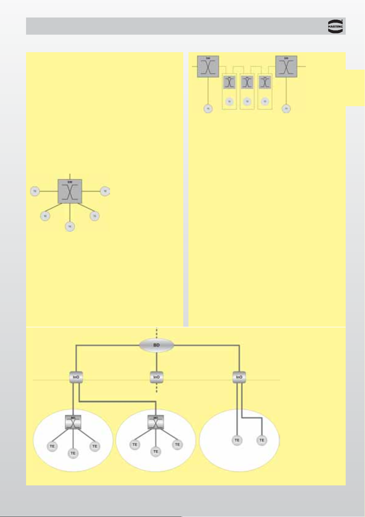
Network topologies
The topologies of Industrial Ethernet networks are
oriented toward the requirements of the equipment
that must be connected. Star, linear, tree and ring
structures are amongst the most common. In practice,
a real installation often consists of a mixture of the
individual structures considered below.
Star
A star structure is characterised by a central signal
distributor (switch) with single connections to all the
network's end devices. Star network structures are
best applied to areas where the density of devices is
high and the physical distances between them is
small, such as small production cells or an individual
production machine.
Tree
A tree topology is formed when a number of stars are
combined into one network. It is used when a complex
installation is divided into smaller regions.
Linear
A linear structure can be implemented by a switch
close to the end device requiring connection, or by a
switch integrated into the end device. Linear
structures are most often used in installations that
are physically extensive, such as conveyor systems,
and for the connection of manufacturing cells.
General
information
Ring (redundancy)
If the ends of a line are closed by an additional
connection, a ring structure results. Ring topologies
are used to protect against line breaks or the failure
of one network component in installations with high
requirements for availability.
PROFInet®transmission system and wiring
The "PROFInet®transmission system and wiring"
guideline defines a method of cabling for Industrial
Ethernet, suitable for industrial application, on the
basis of the fundamental requirements of ISO/IEC
11801.
The PROFInet
®
guideline sets new standards,
because:
l
The component manufacturer is provided with
unambiguous interface specifications
l
The user is provided with simple rules for the
installation
l
He is therefore able to implement networks without
additional Ethernet-specific planning, as with a field
bus.
The PROFInet
®
guideline specifies cables and
connectors with which the user can create an
installation without special calculations relating to the
transmission routes.
Detailed information can be found on the internet
under www.profibus.com
SW = Switch
TE = Terminal Equipment
Star structure
SW = Switch
TE = Terminal
Equipment
Linear structure
ISO / IEC 11801
Structured building network
Structured
machine
network
Manufacturing plant
BD = Building Distributor
MD = Machine Distributor
InO = Industrial Outlet
TE = Terminal Equipment
Page 12

00
.
10
2 100 m
2 100 m
2 100 m
4 100 m
4 100 m
6 100 m
6 100 m
Industrial Ethernet – General information
Cabling
Cables in an industrial environment may be exposed
to extreme mechanical stresses. To ensure adequate
mechanical protection special industrialised cable
may be required, and this can have an effect on
the transmission properties, which may mean that
only relatively short transmission routes can be
implemented. Signal transmission along symmetric
copper cables (twisted pair) must be in accordance
with 100 BASE-TX at 100 Mbit/s (Fast Ethernet). The
transmission medium contains two pairs of twisted,
screened copper cables (twisted pair or star quad)
with a characteristic impedance of 100 Ohms. Only
screened cables and connectors are permitted. The
individual components must satisfy the requirements
for Category 5 in accordance with ISO/IEC 11801.
The entire transmission route must satisfy the
requirements for Class D in accordance with ISO/IEC
11801. Removable connections on the cable side are
made using either RJ 45 or M12 male connectors. On
the device connections are in the form of female
mating connectors. Connecting cables (device
connecting cables and routing cables) accordingly
have male connectors at both ends. Each device is
connected through an active network component.The
transmission cable therefore has identical connectors
at both ends which simplifies installation as the
connecting cable fulfils the function of a patch lead.
The maximum cable length is 100 metres.
As long as the cable and the connectors meet with the
above specifications a maximum cabling length of
100 m can be achieved with up to six connector pairs.
The combination of a male and female connector is
regarded as one pair.
General
information
Table: Transmission route lengths
Wiring example Number of Maximum
connector pairs cabling length
TE = Terminal
Equipment
PMD = PROFInet
®
Machine Distributor
Area
"inside"
Connector
Connector
coupling
Page 13
00
.
11
Industrial Ethernet – General information
Connectors
An important criterion for industrial applications is the
ease with which connection equipment can be
handled on site. Connectors for M12 and for RJ 45
are available for this purpose. They can easily be
assembled on site using standard tools.
In the control cabinet area, PROFInet
®
uses RJ45 in
an IP 20 implementation. It is compatible with office
connectors.
HARTING RJ Industrial®IP 20 Data
Connectors outside the control cabinet must be capable of withstanding the stresses of industrial applications. RJ 45 or M12 connectors with protection to
IP 65 or IP 67 are used in this environment.The RJ 45
in IP 65 / IP 67 implementation has a robust housing
with push pull locking. Special versions allow a level
of protection up to IP 68 to be achieved. The M12
connectors use the screened, D-coded, 4-pin version,
as included by DKE for Industrial Ethernet in the IEC
standard.
HARTING RJ Industrial
®
IP 67 Push Pull
and
HARAX
®
M12-L shielded
Hybrid connectors can be used where distributed field
devices require connection to both the data network
and to a low voltage power supply. A fully contactprotected connector allows the connectors to be
identical at both ends, since the integrated contact
protection means that it is not necessary to alternate
between male and female contact.An RJ 45 providing
IP 67 protection is used to connect twin-pair,
screened data lines for communication and four
electrical contacts provide connection to the power
supply.
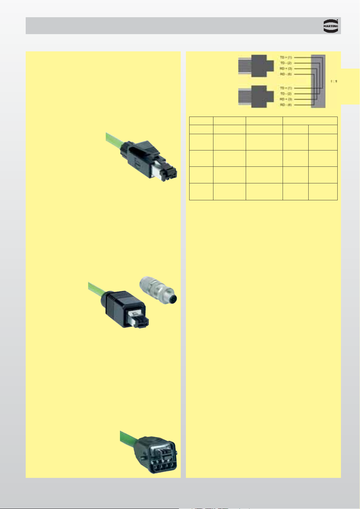
HARTING RJ Industrial®IP 67 Hybrid
Connector
assignment
RJ 45
Signal Function
Conductor colour
Pin assignment
RJ 45 M12
TD+
Transmission
Data + Yellow 1 1
TD-
Transmission
Data - Orange 2 3
RD+ Receiver
Data + White 3 2
RD- Receiver
Data - Blue 6 4
Switches
Switches are devices located in the transmission path
between end devices, and which regenerate signals they
receive before passing them on to their destinations.
They are used to construct networks, and permit data
communication over long distances. Switches suitable
for PROFInet
®
are designed for Fast Ethernet (100
Mbit/s, IEEE 802.3u) and for full duplex transmission. In
full duplex operation, a switch simultaneously sends and
receives data at the same port. Collisions do not occur.
No bandwidth is therefore lost through the Ethernet
collision process. Network planning is made significantly
more straightforward, because it is not necessary to
examine route lengths within a collision domain.
Industrialised switches are used for applications in the
industrial environments. Switches designed for the office
environment can only be used under certain conditions.
One reason for this is that they are not suitable for harsh
industrial surroundings. Secondly, large numbers of
ports can become expensive.
Industrial Outlets
The interface between the structured building network in
accordance with ISO/IEC 11801 and the PROFInet
®
plant cabling is provided by the Industrial Outlet, or InO.
Its function corresponds to the socket outlet used in the
office environment. The InO is manufactured to meet
protection levels IP 65 / IP 67 and is suitable for the
harsh conditions found in the industrial environment.
Source:
PROFInet®Technologie und Anwendung
(PROFInet
®
Technology and Application),
November 2002
PROFInet®transmission system and wiring,
November 2002
General
information
Page 14

00
.
12
Industrial Ethernet – General information
Glossary
10 Base T
The standard for data transmission of 10 Mbit/s
Ethernet through unscreened twisted pair cables
(Category 3, 4 or 5). Each connection is made using
two pairs of wires, one pair being used for data
transmission and the other for data reception.
10 Base FX
The standard for data transmission of 10 Mbit/s
Ethernet through optical fibres. Each connection is
made using two fibres, one fibre being used for data
transmission and the other for data reception.
100 Base TX
The standard for data transmission of 100 Mbit/s
Ethernet through twisted pair cables (Category 5).
Each connection is made using two pairs of wires,
one pair being used for data transmission and the
other for data reception.
100 Base FX
The standard for data transmission of 100 Mbit/s
Ethernet through optical fibres. Each connection is
made using two fibres, one fibre being used for data
transmission and the other for data reception.
Autonegotiation
A procedure defined in Fast Ethernet in which the
devices agree a transmission mode with one another
before the actual data transmission begins (100
Mbit/s or 10 Mbit/s, full or half duplex).
Autocrossing (1:1 cable; cross-over cable)
This function makes it possible to cross the send and
receive lines of twisted pair interfaces automatically.
Devices such as switches that support this function
can be joined through a cable that is wired 1:1 instead
of a cross-over cable.
AWG (American Wire Gauge)
The AWG value describes a cable in terms of the wire
thickness and the permissible attenuation.
Depending on the structure of the cable:
AWG 22 corresponds to a conductor
wire gauge of 0.33 - 0.38 mm²
AWG 24 corresponds to a conductor
wire gauge of 0.21 - 0.25 mm²
AWG 26 corresponds to a conductor
wire gauge of 0.13 - 0.15 mm²
Broadcast telegram
A broadcast telegram is defined as a call to all
network devices ("one to all").
CSMA/CD procedure
Carrier Sense Multiple Access/Collision Detection
Access procedure in Ethernet according to IEEE
802.3. Before sending a message, each network user
first checks whether the transmission medium is free
(Carrier Sense). It then begins to transmit, checking at
the same time whether other devices (Multiple
Access) have also begun to transmit data. If two or
more devices transmit at the same time, a collision
takes place. The devices stop transmitting their data
(Collision Detection). After a randomly chosen time
the next attempt is made when the line is free. In the
CSMA/CD procedure the physical size of the network
is limited by the maximum permissible transmission
time of the data signals across the network, and this
depends on the data rate.
Ethernet
The name of a data network that has been
standardised in IEEE 802.3 since 1985. The term
"Ethernet" is often used as a general term, without
distinguishing between the different versions
(Ethernet, Fast Ethernet etc.).
Fast Ethernet
A fast data network specified in IEEE 802.3 in 1995.
Important parameters: transmission speed 100
Mbit/s, variable packet length 64 - 1522 bytes
(with optional 4 byte tag field).
FEXT (Far End Cross Talk)
A form of crosstalk in which the signals from devices
located at the opposite ends of a twisted pair cable
are superimposed on one another.
Full Duplex
A mode of operation in which one device can
simultaneously send and receive data.
General
information
Page 15

00
.
13
Industrial Ethernet – General information
Gigabit Ethernet
A fast data network specified in IEEE 802.3 in 1999.
Important parameters: transmission speed 1000
Mbit/s, variable packet length 64 – 1518 bytes.
Half Duplex
A mode of operation in which a device either sends or
receives data at any one time. Collision detection is
active in Ethernet for half duplex operation. The
physical size of the network is limited by the
transmission time delays in the devices and the
transmission media.
Hub
The central point in a star arrangement.
A hub – often also called a star coupler – can be used
to connect a number of devices in a star arrangement.
In this arrangement, data packets must take turns to
pass through the hub one after another. Data packets
received at one port are immediately transmitted
again on all the other ports.
Industrial Ethernet
A name for the form of Ethernet used in automation
engineering. Because of the conditions encountered
in industrial applications, the network components
must withstand greater ranges of temperature and
satisfy tougher requirements in terms of availability
and reliability of the network.
Collision Domain
The CSMA/CD access procedure restricts the
transmission time of a data packet from one network
device to another. In accordance with the data rate,
this yields a spatially limited network referred to as a
collision domain. The maximum size of a collision
domain is 4250 m at 10 Mbit/s (Ethernet) and 412 m
at 100 Mbit/s (Fast Ethernet).If a connection operates
in full duplex mode, the physical size can exceed
these limits, because collisions do not then occur.
This requires bridges or switches to be used.
LAN (Local Area Network)
A name for local networks extending up to 10 km.
Multicast Telegram
A multicast telegram is sent to a group of defined
receivers. This group can be reached through one
address (cf. Broadcast Telegram).
NEXT (Near End Cross Talk)
A form of crosstalk in which the signals from devices
located at the same end of a twisted pair cable are
superimposed on one another.
POF (Plastic Optical Fibre)
A name for an optical fibre whose core and sheath are
formed of plastic. POF fibres have a typical core
diameter of 0.98 mm.
PROFInet
®
A network concept that defines the communication
from the field level to the control level utilising Profibus and Ethernet, along with a model for the
network engineering of the entire plant. See also:
www.profibus.com
Queue / Queuing
Queue is a general term for a series of elements or
tasks awaiting sequential processing. In a data
transmission system, a queue is a number of
messages or data packets that are waiting for further
processing or to be transmitted elsewhere. They are
temporarily sorted, and are processed one after
another under the control of appropriate queueing
procedures.
Segmentation / Network Segmentation
Network segmentation is used to set limits to collision
domains, allowing Ethernet networks to achieve
higher performance. A network can be segmented
with the aid, for instance, of switches.
Switched Network
A name for an Ethernet network constructed using
switches.
General
information
Page 16

00
.
14
Notes
General
information
Page 17
01
.
01
Ethernet switches for industrial applications
General information . . . . . . . . . . . . . . . . . . . . . . . . . . . . . . . . . . . . . . . . . . 01.02
Technical characteristics . . . . . . . . . . . . . . . . . . . . . . . . . . . . . . . . . . . . . . 01.03
Ordering information . . . . . . . . . . . . . . . . . . . . . . . . . . . . . . . . . . . . . . . . . 01.03
Accessories . . . . . . . . . . . . . . . . . . . . . . . . . . . . . . . . . . . . . . . . . . . . . . . . 01.04
Industrial Outlets
General information . . . . . . . . . . . . . . . . . . . . . . . . . . . . . . . . . . . . . . . . . . 01.06
Technical characteristics . . . . . . . . . . . . . . . . . . . . . . . . . . . . . . . . . . . . . . 01.07
Ordering information . . . . . . . . . . . . . . . . . . . . . . . . . . . . . . . . . . . . . . . . . 01.07
Accessories . . . . . . . . . . . . . . . . . . . . . . . . . . . . . . . . . . . . . . . . . . . . . . . . 01.08
Active and passive network components
Page
Directory chapter 01
Network
components
Page 18

01
.
02
General description
Advantages
General information
Application fields
Switches divide former collision domains into
point-to-point connections between the network
components and the user equipment involved.
Constructing the network this way prevents
collisions.
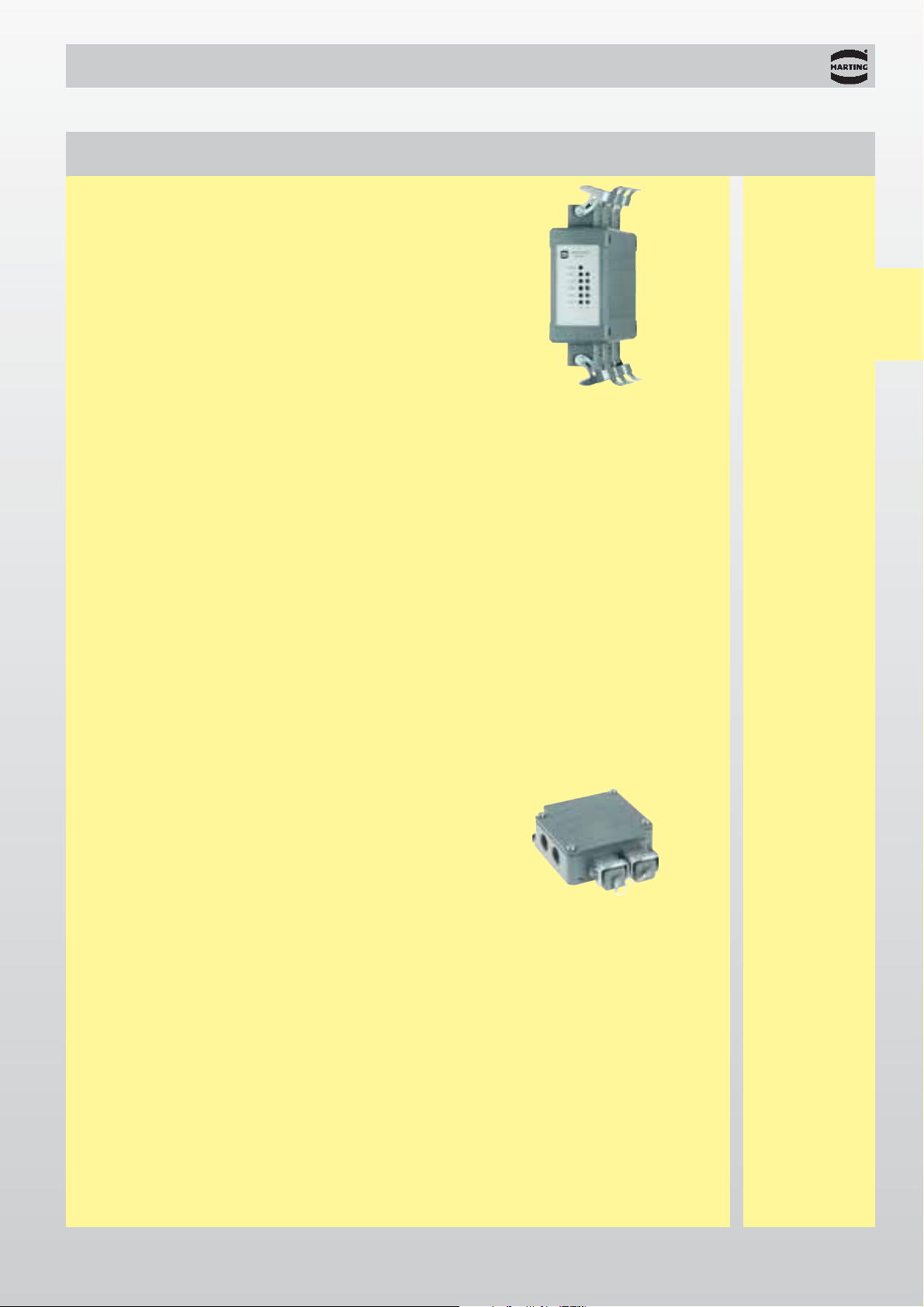
The ESC 67-10 TP05U Fast Ethernet Switch
allows up five items of user equipment to be
connected through shielded twisted pair cable in
accordance with IEC 802.3. The protection level,
temperature range and mechanical stability
satisfy the toughest demands. The Fast Ethernet
Switch can therefore be directly used in industrial
environments.
It allows the amount of cabling needed to
construct industrial networks to be reduced. The
ESC 67-10 TP05U facilitates any kind of network
configuration. All connections are plugged, which
means that assembly is fast and reliable. All
Ethernet interfaces are protected against overvoltage.
l
High IP 65 / IP 67 protection level
l
Robust metal housing
l
Can be used directly in industrial environments
l
EMI, temperature range and mechanical
stability for the toughest demands
l
PROFInet®compatible
l
Industrial automation
l
Automotive industry
l
Wind power
l
Power distribution systems
ESC 67-10 TP05U
Fast Ethernet Switch for industrial applications
Network
components
Page 19

01
.
03
Technical characteristics
Network
components
Function Ethernet Switch in accordance with IEEE 802.3, store and forward switching mode non-blocking,
5 ports unmanaged, autocrossing, autonegotiation, Ethernet (10 Mbit/s) and Fast Ethernet
(100 Mbit/s) diagnostic LEDs (link status, data)
Mechanical data
Hood type Robust metal hood of zinc die-cast
Dimensions 45 x 120 x 87 (W x D x H in mm, without connectors)
Mounting 35 mm top-hat rail according to DIN EN 60715, vertical wall
mounting, horizontal wall mounting
Protection level IP 65 / IP 67
Power supply
Input voltage 24 V DC (18 ... 30 V DC)
Current consumption 100 mA at 24 V DC
Connections Compatible with Han
®
4A connector, redundant power supply
Ethernet Interface
Ports 5 x 10/100 Base-TX, twisted pair, data transmission rate 10 or 100
Mbit/s
Cable Shielded twisted pair (STP) and unshielded twisted pair (UTP),
Category 5
Cascade depth
Linear / star structure Any
Maximum cable length 100 m (with Category 5 cable) in accordance with EN 50 173-1
Available device HARTING RJ Industrial
®
IP 67 Data 3A,
HARTING RJ Industrial
®
IP 67 Push Pull,
HARAX
®
M12-L with D-coding
Environmental conditions
Operating temperature range -40 °C … +70 °C
Relative humidity for operation
30% to 95%, non-condensing
Mechanical stability
Shock / vibration IEC 68-2-27-Ea / IEC 68-2-6-Fc
EMI Interference immunity EN 61000-4-2 … EN 61000-4-6
Interference emission EN 50011, Class A
Ordering information
Switch type Part No. Specification
ESC 67-10 TP05U
20 70 305 3921
HARTING RJ Industrial®IP 67 Data 3A
ESC 67-10 TP05U
20 70 305 3931
HARTING RJ Industrial®IP 67 Push Pull
ESC 67-10 TP05U
20 70 305 3941
M12 D-coding
Page 20

01
.
04
Accessories
Part No.
Switch type Identification Power termination Ethernet termination
Network
components
Further connectors can be found in our catalogue “Heavy Duty Han®connectors”.
1)
Order insert fixing screw 09 20 000 9918 separately
ESC 67-10 TP05U
HARTING RJ Industrial
®
IP 67 Data 3A
Straight metal hood, metric
1)
19 20 003 1440
1)
Protection cover Han®3A 09 20 003 5422 09 20 003 5425
Han
®
4A female insert 09 20 004 2711
Metal cable gland IP 65,
metric M20, cable diameter: 5 - 9 mm 19 00 000 5080
Connector set HARTING RJ Industrial
®
IP 67 Data 3A, metal 09 45 115 1100
Coding pin set 09 45 820 0000
ESC 67-10 TP05U
HARTING RJ Industrial
®
IP 67 Push Pull
HARAX
®
M12-L circular connector 21 03 212 2305
Connector set HARTING RJ Industrial
®
IP 67 Push Pull 09 45 145 1100
ESC 67-10 TP05U
M12 D-coding
HARAX
®
M12-L circular connector 21 03 212 2305
HARAX
®
M12-L circular connector, shielded 21 03 281 1405
Protection cover M12 21 01 000 0003 21 01 000 0003
Page 21

01
.
05
Accessories
Identification Part No. Drawing
Set for top-hat rail mounting
in accordance with DIN EN 60715
20 80 000 0003
Set for vertical wall mounting
20 80 010 0001
Set for horizontal wall mounting
20 80 010 0002
Network
components
Page 22

01
.
06
General description
General information
Advantages
The Industrial Outlet permits a structured building
cable link in accordance with ISO/IEC 11801 for
industrial areas.
The Industrial Outlet INO 67-30 TP02 can be
mounted very simply on walls or beams internally
or externally. The proven LSA+ cable termination
technology means that the cables can be installed
quickly and easily. Lockable, plug-in RJ 45 cables
make the work of extending the Ethernet network
into the production level simple.
In the version with HARTING RJ Industrial
®
IP 67 Data 3A, the Industrial Outlet provides the
interface to the Ethernet cabling as specified for
PROFInet
®
.
l
High IP 65 / IP 67 protection level
l
Robust metal housing
l
Can be used directly in industrial environments
l
Easy mounting on walls or beams
l
LSA+ connection technology makes installation
straightforward
l
Optimum connector technology with high data
security
l
PROFInet®compatible
Industrial Outlet INO 67-30 TP02
Network
components
Field
installation cable
Industrial Outlet for PROFInet
®
(left hand cable entry selected)
Machinery
installation cable
Page 23

01
.
07
Technical characteristics
Mechanical data
Hood type Robust metal hood of aluminium die-cast
Dimensions 105 x 120 x 42 (W x D x H in mm,
without covers; without cable gland)
Mounting Wall mounting
Weight app. 0.6 kg
Protection level IP 65 / IP 67
Ethernet Interface
Suitable for Ethernet, Fast Ethernet
Transmission characteristics In accordance to Category 5, ISO/IEC 11801:2002
and EN 50 173-1
Cable termination 2 x LSA+ connection technology
2 x mateable exit (RJ 45, fit for industrial use)
Available mating interfaces HARTING RJ Industrial
®
IP 67 Data 3A
HARAX
®
M12 with D-coding
Environmental conditions
Operating temperature range 0 °C … +55 °C
Relative humidity for operation
30% to 95%, non-condensing
Mechanical stability
Shock / vibration IEC 68-2-27-Ea / IEC 68-2-6-Fc
EMI Interference immunity EN 61000-4-2 … EN 61000-4-6
INO 67-30 TP02
HARTING RJ Industrial
®
IP 67 Data 3A
with four cable entries
20 70 302 4921
Ordering information
Industrial Outlet type Part No. Specification
Network
components
INO 67-30 TP02
M12 D-coding
with four cable entries
20 70 302 4941
Page 24

01
.
08
Accessories
INO 67-30 TP02
HARTING RJ Industrial
®
IP 67 Data 3A
Metal cable gland IP 65,
metric M20, cable diameter: 5 - 9 mm 19 00 000 5080
Metal blanking piece IP 65, metric M20 19 00 000 5070
Connector set HARTING RJ Industrial
®
IP 67 Data 3A, metal 09 45 115 1100
Coding pin set 09 45 820 0000
INO 67-30 TP02
M12 D-coding
Metal cable gland IP 65,
metric M20, cable diameter: 5 - 9 mm 19 00 000 5080
Metal blanking piece IP 65, metric M20 19 00 000 5070
HARAX
®
M12-L circular connector, shielded 21 03 281 1405
Industrial Outlet type Identification Part No.
Network
components
Page 25

02
.
01
HARTING RJ Industrial®– RJ 45 connectors
General information . . . . . . . . . . . . . . . . . . . . . . . . . . . . . . . . . . . . . . . . . . 02.02
IP 20 Data
connectors . . . . . . . . . . . . . . . . . . . . . . . . . 02.05
IP 67 Push Pull
connectors / panel feed through . . . . . . . . 02.06
IP 67 Data 3A
connectors / panel feed through . . . . . . . . 02.08
IP 67 Hybrid
connectors / panel feed through . . . . . . . . 02.10
HARAX®M12 connectors
Technical characteristics . . . . . . . . . . . . . . . . . . . . . . . . . . . . . . . . . . . . . . 02.12
HARAX
®
circular connector M12-L, shielded . . . . . . . . . . . . . . . . . . . . . 02.13
Customer specific connectors
Han-Brid®Quintax 3A . . . . . . . . . . . . . . . . 02.14
Accessories
. . . . . . . . . . . . . . . . . . . . . . . . 02.16
Connectors Page
Directory chapter 02
Connectors
Page 26

02
.
02
RJ Industrial General information
HARTING RJ Industrial
®
Ethernet connector family
The modular HARTING RJ Industrial®family of
connectors is based on the standard RJ 45 connector
pattern, and is specifically developed for use in harsh
industrial environments. It points the way forward
in connecting Ethernet devices in industrial
applications. In many circumstances it is necessary
for connectors to be assembled on site, regardless of
whether they are being used for power or
communication. HARTING are making consistent use
of their
HARAX
®
rapid termination technology, which
has been proven in many industrial applications.With
HARAX
®
the user can terminate the cable at the
connectors without the need for special tools. The
design of the HARTING RJ Industrial
®
family of
connectors allows for quick and easy termination and
connection to Ethernet devices in either data only or
hybrid networks.
HARTING RJ Industrial
®
is the only RJ 45 connector
in the world that allows robust Ethernet cables with a
solid and stranded AWG 22 cross section to be
connected using IDC technology. The heart of each of
these connectors is the RJ 45 data module with fast
termination technology. This functions without
needing to strip insulation from the cores and without
special tools, creating a gas-tight connection, secure
against vibration. The data module has four
HARAX
®
fast termination contacts.These make reliable contact
with stranded, industry-standard Category 5 cables
with dimensions from AWG 22 to 24, and solid cables
with conductor cross-sections from AWG 22 to 23.
HARTING have developed a
complete family of connectors
around this innovative data
module, meeting all the needs
of industrial environments.
Solutions for IP 20 and IP 67
protection levels, standard,
push pull and latching clip-locks
are available.
Data and hybrid cables can be used. The user can fit
stranded cores with a cross section of 1.5 mm² for the
IDC power contacts on the Hybrid version, and these
can be loaded with up to 16 A.
At the device end, panel feed throughs or
couplings integrated directly into the device can
be accomodated. Consistent application of SMD
components for both data and power at the device
end keeps manufacturing costs low, and permits high
packing density within the assembly.
Field assembly of Industrial Ethernet
connectors
The facility of on-site assembly was given high
priority in the development of the new HARTING RJ
Industrial
®
family of connectors. As a result, the
connector is not just quicker to terminate, but is also
easier to handle due to the reduced number of
individual parts.
All of the HARTING RJ Industrial
®
range can be reterminated up to ten times. An electrician can carry
out assembly of the IP 20 Data version on site in less
than one minute, while the IP 67 Hybrid version
requires less than three minutes. Dismantling is just
as quick. New operatives can also learn the individual
steps involved very quickly and carry them out
reliably.
Another advantage of the quick-connection technology is provided by the industrial-quality screening of
the data module in the connector. Termination of the
screen which in the past has been achieved by
crimping is no longer necessary. In the
RJ Industrial connection technology,
a pair of screening plates are
simply pushed over the data
module, and pressed together
with an audible "click". With
this, complete, 360 degree
connection of the screen
and the sheath is
achieved.
Various special tools for handling the RJ 45 data
module and the power leads are unnecessary.
HARTING supplies all the components in a complete
set.
Connectors
Page 27

02
.
03
RJ Industrial
!!!!
!
!
!!
IP 20 Data
IP 67 Push Pull
IP 67 Hybrid
IP 67 Data 3A
IP 67 Push Pull IP 67 Hybrid IP 67 Data 3A
Specified for PROFInet
®
From the very beginning, HARTING saw it as their
task to set a broad standard for Ethernet in industrial
environments through a uniform connector solution.
Through its involvement in the PNO (PROFIBUS
Nutzerorganisation e.V.), the IAONA (Industrial
Automation Open Networking Alliance e.V.), the
DKE (Deutsche Kommission Elektrotechnik
Elektronik Informationstechnik) and also with the
IEC (International Electrotechnical Committee),
HARTING contributed to advancing the specification
of industry-standard Ethernet connectors. At the
beginning of 2003, the PNO decided to use the
HARTING solution of the RJ Industrial family as the
general concept for PROFInet
®
.
In addition to this an international standardisation
process was initiated, because the HARTING
approach is not a proprietary system, but an open
solution for Industrial Ethernet interfaces.
General information
Connectors
Device side
IP 20 Data
Standard
RJ 45 jack
Cable side
Mating compatibility of the HARTING RJ Industrial®family
Page 28

02
.
04
RJ Industrial
1 2 3
6 5 4
7 8 9
12 11 10
6 Place the data module and the splicing piece into
the supplied IDC assembly tool
7 Press the data module and the IDC assembly tool
together, to make the insulation displacement
contact
8 Remove the assembled data module from the
IDC assembly tool
9 Put on the upper screen plate, and push it over
the cable screen
10 Put the lower screen plate in place, and latch it
to the upper screen plate with an audible
click
11 Push the housing over the assembled data
module, latching it into place with an audible click
12 Tighten the cable gland
Assembly operations
HARTING RJ Industrial
®
IP 20 Data
Only a few steps are necessary to quickly and reliably
connect an Industrial Ethernet cable to a HARTING
RJ Industrial
®
connector with IDC connection
technology.
1 Push the housing complete with cable gland over
the cable outer insulation
2 Strip the correct length of outer insulation and
screening braid
3 Prepare the cores to match the splicing piece in
accordance with the colour code
4 Insert the cores into the splicing piece to the
required depth
5 Place the splicing piece on the RJ 45 data
module and engage it
General information
Connectors
Page 29

02
.
05
RJ Industrial
09 45 151 1100
Technical characteristics General information
Connectors
IP 20 Data connectors
Connector set
incl. housing, cable gland
and instruction manual
Identification Part No. Drawing Dimensions in mm
Transmission properties in accordance with
Category 5 ISO/IEC 11 801:2002 and EN 50173-1
Protection level: IP 20
Mating interface: RJ 45 in accordance with
IEC 60603-7
Wire gauge data
1)
: AWG 22 - 24 stranded
AWG 22 - 23 solid
Temperature range: -40 °C … +70 °C
Cable sheath diameter: 6.5 mm - 6.9 mm
Mating cycles: min. 750
Housing material: Thermoplastic, black
The IP 20 Data connector is the smallest and only
RJ 45 Ethernet connector in the world to which
AWG-22 cables can be connected with IDC technology.
The connector is designed with a standard grid of just
14 mm, which guarantees maximum packing density in
the application. An additional latching clip on the
housing makes its significantly easier to unlock the
connector.
This connector can be assembled on site, permitting
Industrial Ethernet installation cable to be connected
directly to IP 20 devices located inside a control
cabinet. Special panel feed through to provide the
transition between protection level IP 67 and IP 20 is
therefore not necessary. This lessens the installation
work required from the customer, while the reduced
number of contact points offers increased reliability.
Connectors
1)
Details see technical data sheet
Page 30

02
.
06
09 45 145 1100
RJ Industrial
Technical characteristics General information
IP 67 Push Pull connectors
Connector set
incl. housing, cable gland
and instruction manual
Identification Part No. Drawing Dimensions in mm
Transmission properties in accordance with
Category 5 ISO/IEC 11 801:2002 and EN 50173-1
Protection level: IP 67
Mating interface: RJ 45 in accordance with
IEC 60603-7
Wire gauge data
1)
: AWG 22 - 24 stranded
AWG 22 - 23 solid
Temperature range: -40 °C … +70 °C
Cable sheath diameter: 6.5 mm - 7.2 mm
Mating cycles: min. 750
Housing material: Thermoplastic, black
The IP 67 Data version in a push pull housing is an
entirely new development with innovative housing
locking technology. The housing of the connector is
locked tightly to the hood by means of a locking sleeve
that surrounds it. The connector can be locked and
unlocked using one hand and only minimal force. In
spite of its high degree of protection, the housing is
very compact, and is ideally suited for compact
industrial applications.
The HARTING RJ Industrial
®
Push-Pull is thus the
smallest IP 67 Industrial Ethernet connector based on
RJ 45 with IDC connection technology in the world.
Connectors
Connectors
1)
Details see technical data sheet
Page 31
02
.
07
09 45 245 1100
RJ Industrial
Technical characteristics General information
IP 67 Push Pull panel feed through
Identification Part No. Drawing Dimensions in mm
Connectors
Panel feed through set
incl. housing
and instruction manual
Transmission properties in accordance with
Category 5 ISO/IEC 11 801:2002 and EN 50173-1
Protection level: IP 67
Mating interface
internal and external: RJ 45 jack in accordance
with IEC 60603-7
Temperature range: -40 °C … +70 °C
Panel cut out: 21 x 27 mm
Mating cycles: min. 750
Housing material: Thermoplastic, black
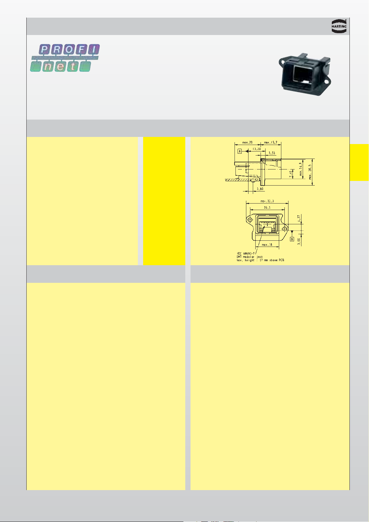
The IP 67 Data version in a push pull housing is an
entirely new development with innovative housing
locking technology. The housing of the connector is
locked securely to the hood by means of a surrounding
locking sleeve. In spite of the high degree of protection,
the panel feed through is very compact, having a space
requirement of just 21 x 27 mm, the same space as for
a M12 connector.
The Push Pull panel feed through is compatible with
RJ 45 connectors, which means that standard patch
cables for service and test purposes can also be used
here.
The data lines are connected at the rear via an RJ 45
jack meeting IP 20.
Connectors
Page 32

02
.
08
09 45 125 1100
09 45 115 1100
09 45 820 0000
RJ Industrial
Technical characteristics General information
IP 67 Data 3A connectors
Plastic version
Metal version
Coding pin set
Identification Part No. Drawing Dimensions in mm
Connectors
Connector set
incl. housing, cable gland
and instruction manual
Transmission properties in accordance with
Category 5 ISO/IEC 11 801:2002 and EN 50173-1
Protection level: IP 67/65
Mating interface: RJ 45 in accordance with
IEC 60603-7
Wire gauge data
1)
: AWG 22 - 24 stranded
AWG 22 - 23 solid
Temperature range: -40 °C … +70 °C
Cable sheath diameter: 6.5 mm - 6.9 mm
Mating cycles: min. 750
Housing material: Thermoplastic, black
Zinc die cast, grey
The IP 67 Data version of the RJ Industrial is based on
the RJ 45 Data module, integrated into a standard
Han
®
3A industry housing that can be used for most
industrial applications. The housing is optionally
available in plastic or metal, and offers protection level
IP 67/65.
Implementing a uniform pattern for all the connectors
based on the Han
®
3A contour for data and hybrid
solutions means that all versions are plug-compatible
for data signals. Optional coding prevents incorrect
mating up to four different connectors.
1)
Details see technical data sheet
Connectors
Page 33

02
.
09
09 45 225 1100
09 45 215 1100
09 45 820 0000
RJ Industrial
Technical characteristics General information
IP 67 Data 3A panel feed through
Identification Part No. Drawing Dimensions in mm
Plastic version
Metal version
Coding pin set
Connectors
Panel feed through set
incl. housing
and instruction manual
Transmission properties in accordance with
Category 5 ISO/IEC 11 801:2002 and EN 50173-1
Protection level: IP 67/65
Mating interface
internal and external: RJ 45 jack in accordance
with IEC 60603-7
Panel cut out: 22 x 22 mm
Temperature range: -40 °C … +70 °C
Mating cycles: min. 750
Housing material: Thermoplastic, black
Zinc die cast, grey
The IP 67 panel feed through data version of the
RJ Industrial is based on an RJ 45 jack, integrated into
a Han
®
3A housing that can be used for most industrial
applications. The housing is optionally available in
plastic or metal, and offers protection level IP 67/65.
Implementing a uniform plug pattern for all the
connectors based on the 3A contour for data and hybrid
solutions means that all versions are plug-compatible
for data signals. Optional coding prevents incorrect
mating up to four different connectors. The panel feed
through is compatible with RJ 45 connectors, which
means that standard patch cables for service and test
purposes can be used. The data lines are connected at
the rear via an RJ 45 jack meeting IP 20.
Connectors
Page 34

02
.
10
09 45 125 1300
RJ Industrial
Technical characteristics General information
IP 67 Hybrid connectors
Identification Part No. Drawing Dimensions in mm
Connectors
Connector set
incl. housing, cable gland
and instruction manual
Transmission properties in accordance with
Category 5 ISO/IEC 11 801:2002 and EN 50173-1
Protection level: IP 67
Mating interface: RJ 45 in accordance
with IEC 60603-7
plus 4 x power supply
Wire gauge data: AWG 22 - 24 stranded
AWG 22 - 23 solid
Wire gauge
power supply: 1.5 mm² stranded
Working voltage
power supply: 24 V
Working current
power supply: 16 A
Temperature range: -40 °C … +70 °C
Cable sheath diameter: 10 mm - 11 mm
Mating cycles: min. 500
Housing material: Thermoplastic, black
In the RJ Industrial Hybrid connector, HARTING has
developed an interface solution that integrates the
data lines and the power supply into one connector for
hybrid Ethernet networks. The connector's geometry
nevertheless maintains a clear separation between
the data and the power contacts. This brings a
significant reduction in the costs of installation and of
field devices suitable for industrial application with
hybrid cabling.
The four power contacts of the hybrid module have also been designed with
HARAX
®
rapid termination
technology, allowing stranded cables of up to 1.5 mm²
to be connected.
The physical length of the hybrid IP 67 version of the
industry standard Han
®
3A housing has been
reduced by 30 per cent, making it significantly
easier to handle and to use in compact industrial
applications.
Connectors
Page 35

02
.
11
09 45 225 1300
RJ Industrial
09 45 820 0000
Technical characteristics General information
IP 67 Hybrid panel feed through
Identification Part No. Drawing Dimensions in mm
Connectors
Panel feed through set
incl. housing
and instruction manual
Coding pin set
Transmission properties in accordance with
Category 5 ISO/IEC 11 801:2002 and EN 50173-1
Protection level: IP 67
Mating interface external: RJ 45 jack in accordance
with IEC 60603-7
plus 4 x power supply
Mating interface internal: RJ 45 jack in accordance
with IEC 60603-7
plus 4 x power supply
with cage clamp 1.5 mm²
Working voltage
power supply: 24 V
Working current
power supply: 16 A
Panel cut out: 22 x 22 mm
Temperature range: -40 °C … +70 °C
Mating cycles: min. 500
Housing material: Thermoplastic, black
In the RJ Industrial Hybrid connector, HARTING has
developed an interface solution that integrates the
data lines and the power supply into one connector for
hybrid Ethernet networks. The connector’s geometry
nevertheless maintains a clear separation between
the data and the power contacts. This brings a
significant reduction in the costs of installation and of
field devices suitable for industrial application with
hybrid cabling.
The panel feed through is compatible with RJ 45
connectors, which means that the standard patch
cables for service and test purposes can be used. The
data lines are connected at the rear via an RJ 45 jack,
while the power lines use a cage clamp terminal.
Connectors
Page 36

02
.
12
À
Á
Â
Å
M12-L, shielded
HARAX
®
circular connector M12-L Technical characteristics
Assembly details General information
Transmission characteristics in accordance with DIN 50 173-1
Working voltage 32 V
Working current 4 A
(see current carrying capacity)
Coding D
Wire gauge 0.25 mm² - 0.34 mm²
AWG 24 - AWG 22 stranded
Diameter of individual strands > 0.1 mm
Conductor insulation material PVC
Conductor diameter 1.2 mm - 1.6 mm
Cable diameter 5.5 mm - 7.2 mm
Working temperature -25 °C ... +85 °C
Temperature during connection -5 °C ... +50 °C
Protection level IP 67
Number of terminations with
same cable cross section 10
Current carrying capacity
The current carrying capacity is limited by maximum temperature
of materials for inserts and contacts including terminals. The
current capacity-curve is valid for continuous, not interrupted
current-loaded contacts of connectors when simultaneous power
on all contacts is given, without exceeding the maximum
temperature.
Control and test procedures according to DIN IEC 60 512-3.
1. Remove cable sheath
2. Put screening braid in place, and fix with sliding
ring
3. Assemble
HARAX
®
elements
4. Cut off the ends of the cables at the splicing ring
and the screening braid at the sliding ring
5. Screw tight
6. The coupling ring must be screwed as far as the
stop on the contact carrier.
Attention!
For reconnection cut off the used cable end and
repeat steps 1 to 6.
The
HARAX
®
principle
l
The cores are terminated automatically by screwing
the coupling ring onto the contact carrier. This
guides the cores through ducts in the splicing ring,
positioning them accurately. A new design of
insulation displacement contact blade, guided by
contact ducts permits the individual cores to be
terminated reliably.
l
The screening braid is passed laterally through the
slotted seal, and is fixed by a sliding ring.The sliding
ring provides a transition between the screen and
the housing.
l
After tightening the coupling ring, the sealing ring
provides cable strain relief and protection to IP 67
against dust and water spray.
Working current [A]
Ambient temperature [°C]
1 = Wire gauge
0.34 mm²
M12-L, shielded
Frequency [Hz]
Near end crosstalk [dB]
Limit acc. ISO/IEC 11801
M12-L, shielded
Connectors
Screening attenuation diagram
Page 37

02
.
13
M12 4 21 03 281 1405
M12 21 01 010 2003
HARAX
®
circular connector M12-L
No. of
Identification Series contacts Part No. Drawing Dimensions in mm
Circular connector
M12-L, shielded
male
D-coding for Ethernet
straight version
Seal
M12-L
Connectors
View:
Mating side
Page 38

02
.
14
Han-Brid®Quintax 3A
Description Data interface
General information
Power supply
The Han-Brid®series combines a data and power
interface for industrial communication in the
smallest possible space.
The components in this hybrid connector family
all contain the facility to load power contacts rated
at 50 V 10 A to provide a power supply for
distributed devices. This means that a power
supply can be provided to all devices in a bus
structure via a single connector.
l
Han-Brid®Quintax 3A for 4-wire bus systems
and Ethernet networks with continuous screen
connection.
The contact inserts can be used either in the
standard plastic housing or the metal housing
from the Han
®
3A series. The protection level of
the housings corresponds to DIN EN 60 529,
IP 65.
l
Can be connected to screened 4-wire cables
l
Can be used for all 4-wire bus systems
l
Accepts screened cable with a diameter from
3 to 9.5 mm
l
Continuity of screen is independent of housing
potential
l
Cable connection in accordance with DIN EN
50 173, Category 5
l
Standard Han D®male and female crimp
contacts
l
Rated current: 10 A
l
Rated voltage: 50 V
l
Connection range: 0.14 to 2.5 mm² stranded
l
Approval: UL
4 contacts + screening
+ 2 power contacts
For use in Han
®
3A hoods with metric cable gland
Connectors
Technical characteristics
Transmission properties in accordance with
Category 5 ISO/IEC 11 801:2002 and EN 50173-1
Protection level IP 65
Wire gauge data: 0.14 - 2.5 mm² stranded
AWG 26 - 14
Wire gauge
power supply: 0.14 - 2.5 mm² stranded
AWG 26 - 14
Temperature range: -40 °C … +70 °C
Cable sheath diameter: 3 mm - 9.5 mm
Mating cycles: ≥ 500
Page 39

02
.
15
Han-Brid®Quintax 3A
– 09 15 003 3001 09 15 003 3101
3 - 9,5 09 15 004 3013 09 15 004 3113
M
M
F
F
Cable-Ø
Part No.
Identification mm Male insert (M) Female insert (F) Drawing Dimensions in mm
4 contacts + screening
+ 2 power contacts
For use in Han
®
3A hoods with metric cable gland
Quintax insert
Quintax Z contact
Zinc alloy
Order crimp contacts
separately
see page 02.16
Cable clamp for cable
diameter 3 - 6 and
6 - 9.5 mm is supplied
with the inserts
Connectors
Page 40

02
.
16
Accessories
Wire gauge
Part No.
Identification (mm2) Male contacts Female contacts Drawing Dimensions in mm
Crimp contacts
silver plated
0.14-0.37
09 15 000 6104 09 15 000 6204
0.5 09 15 000 6103 09 15 000 6203
0.75 09 15 000 6105 09 15 000 6205
1.0 09 15 000 6102 09 15 000 6202
1.5 09 15 000 6101 09 15 000 6201
2.5 09 15 000 6106 09 15 000 6206
gold plated
0.14-0.37
09 15 000 6124 09 15 000 6224
0.5 09 15 000 6123 09 15 000 6223
0.75 09 15 000 6125 09 15 000 6225
1.0 09 15 000 6122 09 15 000 6222
1.5 09 15 000 6121 09 15 000 6221
2.5 09 15 000 6126 09 15 000 6226
Connectors
0.14-0.37 mm2AWG 26-22 0.90 mm 8 mm
0.5 mm
2
AWG 20 1.10 mm 8 mm
0.75 mm
2
AWG 18 1.30 mm 8 mm
1. mm
2
AWG 18 1.45 mm 8 mm
1.5 mm
2
AWG 16 1.75 mm 8 mm
2.5 mm
2
AWG 14 2.25 mm 6 mm
Wire gauge
Identification (mm2) Part No.
HARTINGcrimping tool
with locators
for all Han D
®
contacts
0.14 - 1.5 mm² 09 99 000 0021
BUCHANANcrimping tool
for all Han D®contacts
0.14 - 4.0 mm² 09 99 000 0001
Removal tool
for Han D®contacts 09 99 000 0012
Locator
09 99 000 0311
Plug gauge
0.14-0.25
09 99 000 0203
0.37 09 99 000 0125
0.5-1.0
09 99 000 0007
1.5 09 99 000 0008
2.5 09 99 000 0007
Wire gauge Stripping
ø
(stranded) length
Page 41

02
.
17
Accessories
Identification Part No. Drawing Dimensions in mm
Hoods
l
Han®3A hood with integral sealing – Protection level: IP 65
IP 67 under preparation
l
Plastic versions
l
Metal versions
l
EMC versions
l
Han®HPR (pressure tight and EMI protected)
l
Han-Brid®Quintax can be fitted exclusively in hoods with metric threads
Further information can be found in our catalogue “Heavy Duty Han®connectors”
Hood
straight, metric Plastic grey
1)
19 20 003 0423
1)
Plastic black
1)
19 20 003 0426
1)
Metal
1)
19 20 003 1443
1)
HPR 19 40 003 0400
Hood
right angled, metric Plastic grey
1)
19 20 003 0623
1)
Plastic black
1)
19 20 003 0626
1)
Metal
1)
19 20 003 1643
1)
Housing
Plastic grey 09 20 003 0320
Plastic black 09 20 003 0327
Metal 09 20 003 0301
HPR 09 40 003 0301
Cable to cable hood
metric Plastic grey 19 20 003 0720
Plastic black 19 20 003 0727
Metal 19 20 003 1750
Cable gland
metric, M20,
cable-Ø 5 - 9 mm Plastic grey, IP 65 19 00 000 5180
cable-Ø 5 - 9 mm Metal, IP 65 19 00 000 5080
cable-Ø 6 - 12 mm Plastic black, IP 65 19 00 000 5132
1)
with integral sealing
Protection cover Han®3A
Plastic black
1)
09 20 003 5409
1)
Metal
1)
09 20 003 5425
1)
Connectors
Page 42

02
.
18
Notes
Connectors
Page 43

03
.
01
Cables for Industrial Ethernet . . . . . . . . . 03.02
Cable assemblies for Industrial Ethernet 03.04
System cables
Page
Directory chapter 03
System
cables
Page 44

03
.
02
09 45 600 0100
System cables
Cable for Industrial Ethernet
Industrial Ethernet Shielded
Twisted Pair Standard Cable
meeting the Category 5 cabling standard.
Specially for industrial applications in
structured cabling of Ethernet networks.
Radially symmetrical structure, with four
solid AWG 22/1 cores arranged as star
quad. Particularly good immunity to electromagnetic interference through double
screening.
The cable is specially designed for
assembly to the HARTING RJ Industrial
®
family of connectors.
Length: 100 m reel
Electrical properties
Cabling standard in accordance
with ISO/IEC 11801:2002: Category 5
Loop resistance: max. 124 Ohm / km
Insulation resistance: min. 500 MOhm x km
Characteristic impedance
at 1 MHz .... 100 MHz: (100 ± 15) Ohm
Near end crosstalk attenuation
at 100 MHz (typical): 50 dB / 100 m
Far end crosstalk attenuation
at 100 MHz (typical): 45 dB / 100 m
Attenuation coefficient
at 100 MHz (typical): 19.5 dB / 100 m
Mechanical properties
Wire type: 2YY(ST)CY 2X2X0.64/1.5-100 GN
Sheath: PVC green dia. (6.5 ± 0.2) mm
Cores: solid, AWG 22/1 (dia. 0.64 mm)
Core colour sequence: white - yellow - blue - orange
Service temperature: -40 °C … +70 °C
Installation temperature: -20 °C … +60 °C
Storage/transport
temperature: -40 °C … +70 °C
Minimum bending radius: Multiple bending 15 x diameter
One time 10 x diameter
Max. permissible tension: 150 N
Description Part No. Technical characteristics
System
cables
Page 45

03
.
03
09 45 600 0101
System cables
Cable for Industrial Ethernet
Industrial Ethernet Shielded
Twisted Pair Trailing Cable
meeting the Category 5 cabling standard.
Specially designed for industrial application
of Ethernet cables in power chains and
moving machine parts. Radially
symmetrical structure, with four stranded
AWG 22/7 cores arranged in star quad
format. Particularly good immunity to
electromagnetic interference through
double screening.
This cable is specially designed for
assembly to the HARTING RJ Industrial
®
family of connectors. Halogen-free and
silicone-free polyurethane (PUR) external
sheath.
Length: 100 m reel
Electrical properties
Cabling standard in accordance
with ISO/IEC 11801:2002: Category 5
Loop resistance: max. 120 Ohm / km
Insulation resistance: min. 500 MOhm x km
Characteristic impedance
at 1 MHz .... 100 MHz: (100 ± 15) Ohm
Near end crosstalk attenuation
at 100 MHz (typical): 50 dB / 100 m
Far end crosstalk attenuation
at 100 MHz (typical): 45 dB / 100 m
Attenuation coefficient
at 100 MHz (typical): 22 dB / 100 m
Mechanical properties
Wire type: 2YH(ST)C11Y 2X2X0.75/1.5-100
LI GN VZN FRNC
Sheath: PVC green dia. (6.5 ± 0.2) mm
Cores: stranded, AWG 22/7
(dia. 0.75 mm)
Core colour sequence: white - yellow - blue - orange
Service temperature: -40 °C … +70 °C
Installation temperature: -20 °C … +60 °C
Storage/transport
temperature: -50 °C … +70 °C
Minimum bending radius: Multiple bending 15 x diameter
One time 10 x diameter
Max. permissible tension: 150 N
Description Part No. Technical characteristics
System
cables
Page 46

03
.
04
System cables
IP 20 Length: 1.5 m 09 45 751 1123
3.0 m 09 45 751 1125
5.0 m 09 45 751 1127
10.0 m 09 45 751 1151
20.0 m 09 45 751 1153
50.0 m 09 45 751 1156
100.0 m 09 45 751 1161
Cable assemblies for Industrial Ethernet
Assembled
and Tested System Cables
for the structured cabling of Industrial
Ethernet networks in accordance with the
PROFInet
®
guideline, based on RJ 45
connectors and AWG 22/1 (solid) Shielded
Twisted Pair Cable.
Cable type: HARTING RJ Industrial
®
Ethernet
Shielded Twisted Pair
Standard Cable, AWG 22/1 (solid)
Mating face: RJ 45 in acc. with IEC 60603-7
Transmission properties in
accordance with ISO/IEC
11 801:2002: Class D, 100% tested
Connectors: 2x HARTING RJ Industrial
®
IP 20 Data with IDC fast
termination technology
Protection level: IP 20
Description Part No. Technical characteristics
Signal Function
Conductor
RJ 45 RJ 45
colour pin no. pin no.
right left
TD+ Transmission Data+ Yellow 1 1
TD- Transmission Data- Orange 2 2
RD+ Receiver Data+ White 3 3
RD- Receiver Data- Blue 6 6
Pin assignment in accordance with PROFInet®specification:
System
cables
Further system cables available on request.
Page 47

03
.
05
System cables
IP 65 / 67 Length: 1.5 m 09 45 715 1123
metal 3.0 m 09 45 715 1125
5.0 m 09 45 715 1127
10.0 m 09 45 715 1151
20.0 m 09 45 715 1153
50.0 m 09 45 715 1156
100.0 m 09 45 715 1161
Cable assemblies for Industrial Ethernet
Assembled
and Tested System Cables
for the structured cabling of Industrial
Ethernet networks in accordance with the
PROFInet
®
guideline, based on RJ 45
connectors and AWG 22/1 (solid) Shielded
Twisted Pair Cable.
Cable type: HARTING RJ Industrial
®
Ethernet
Shielded Twisted Pair
Standard Cable, AWG 22/1 (solid)
Mating face: RJ 45 in acc. with IEC 60603-7
Transmission properties in
accordance with ISO/IEC
11 801:2002: Class D, 100% tested
Connectors: 2x HARTING RJ Industrial
®
IP 67 Data 3A metal with IDC fast
termination technology
Protection level: IP 65 / 67 (when mated)
Description Part No. Technical characteristics
Signal Function
Conductor
RJ 45 RJ 45
colour pin no. pin no.
right left
TD+ Transmission Data+ Yellow 1 1
TD- Transmission Data- Orange 2 2
RD+ Receiver Data+ White 3 3
RD- Receiver Data- Blue 6 6
Pin assignment in accordance with PROFInet®specification:
System
cables
Further system cables available on request.
Page 48

03
.
06
Notes
System
cables
Page 49

09 15 000 6101 02.16
09 15 000 6102 02.16
09 15 000 6103 02.16
09 15 000 6104 02.16
09 15 000 6105 02.16
09 15 000 6106 02.16
09 15 000 6121 02.16
09 15 000 6122 02.16
09 15 000 6123 02.16
09 15 000 6124 02.16
09 15 000 6125 02.16
09 15 000 6126 02.16
09 15 000 6201 02.16
09 15 000 6202 02.16
09 15 000 6203 02.16
09 15 000 6204 02.16
09 15 000 6205 02.16
09 15 000 6206 02.16
09 15 000 6221 02.16
09 15 000 6222 02.16
09 15 000 6223 02.16
09 15 000 6224 02.16
09 15 000 6225 02.16
09 15 000 6226 02.16
09 15 003 3001 02.15
09 15 003 3101 02.15
09 15 004 3013 02.15
09 15 004 3113 02.15
09 20 000 9918 01.04
09 20 003 0301 02.17
09 20 003 0320 02.17
09 20 003 0327 02.17
09 20 003 5409 02.17
09 20 003 5422 01.04
09 20 003 5425 01.04
09 20 003 5425 02.17
09 20 004 2711 01.04
09 40 003 0301 02.17
09 45 115 1100 01.04
09 45 115 1100 01.08
09 45 115 1100 02.08
09 45 125 1100 02.08
09 45 125 1300 02.10
09 45 145 1100 01.04
09 45 145 1100 02.06
09 45 151 1100 02.05
09 45 215 1100 02.09
09 45 225 1100 02.09
09 45 225 1300 02.11
09 45 245 1100 02.07
09 45 600 0100 03.02
09 45 600 0101 03.03
09 45 715 1123 03.05
09 45 715 1125 03.05
09 45 715 1127 03.05
09 45 715 1151 03.05
09 45 715 1153 03.05
09 45 715 1156 03.05
09 45 715 1161 03.05
09 45 751 1123 03.04
09 45 751 1125 03.04
09 45 751 1127 03.04
09 45 751 1151 03.04
09 45 751 1153 03.04
09 45 751 1156 03.04
09 45 751 1161 03.04
09 45 820 0000 01.04
09 45 820 0000 01.08
09 45 820 0000 02.08
09 45 820 0000 02.09
09 45 820 0000 02.11
09 99 000 0001 02.16
09 99 000 0007 02.16
09 99 000 0008 02.16
09 99 000 0012 02.16
09 99 000 0021 02.16
09 99 000 0125 02.16
09 99 000 0203 02.16
09 99 000 0311 02.16
19 00 000 5070 01.08
19 00 000 5080 01.04
19 00 000 5080 01.08
19 00 000 5080 02.17
19 00 000 5132 02.17
19 00 000 5180 02.17
19 20 003 0423 02.17
19 20 003 0426 02.17
19 20 003 0623 02.17
19 20 003 0626 02.17
19 20 003 0720 02.17
19 20 003 0727 02.17
19 20 003 1440 01.04
19 20 003 1443 02.17
19 20 003 1643 02.17
19 20 003 1750 02.17
19 40 003 0400 02.17
20 70 302 4921 01.07
20 70 302 4941 01.07
20 70 305 3921 01.03
20 70 305 3931 01.03
20 70 305 3941 01.03
20 80 000 0003 01.05
20 80 010 0001 01.05
20 80 010 0002 01.05
21 01 000 0003 01.04
21 01 010 2003 02.13
21 03 212 2305 01.04
21 03 281 1405 01.04
21 03 281 1405 01.08
21 03 281 1405 02.13
10
.
01
List of part numbers
Part No. Page Part No. Page Part No. Page
Part No.
Page 50

Production plants – worldwide
Subsidiary companies
Espelkamp / Germany – Plant 1 Espelkamp / Germany – Plant 2 Espelkamp / Germany – Plant 3
Espelkamp / Germany – Plant 4 Espelkamp / Germany – Plant 5
Zhuhai / China Biel / Switzerland Northampton / Great Britain
Page 51

MO/04.04.03/6.0 98 11 004 0201
Austria
HARTING Ges. m. b. H.
Deutschstraße 3, A-1230 Wien
Phone +43 1 /6 16 2121
Fax +43 1 / 6 16 21 21-21
E-Mail: at@HARTING.com
Belgium
HARTING N.V. / S.A.
Doornveld 8, B-1731 Zellik
Phone +32 2 /4 66 0190
Fax +32 2 / 4 66 78 55
E-Mail: be@HARTING.com
Br
azil
HARTING Ltda.
Av. Dr. Lino de Moraes Leme, 255
Pq. Jabaquara
CEP 04360-001 - São Paulo - SP - Brazil
Phone +55 11 /50 34 -00 73
Fax +55 11 / 50 34 - 47 43
E-Mail: br@HARTING.com
China
HARTING (HK) Limited
Shanghai Representative Office
Room 2302 Hong Kong Plaza South Tower
283 Huai Hai Road (M)
Shanghai 200021, China
Phone +86 21 - 63 90 - 69 35, 63 90 - 6936
Fax +86 21- 6390 - 63 99
E-Mail: ChinaSales@HARTING.com.cn
Cz
ech Repub
lic
HARTING spol. s.r.o.
Mlýnská 2, 160 00 Praha 6
Phone +4 20 2 /203 80450
Fax +420 2 / 203 80451
E-Mail: HARTING@HARTING.cz
Finland
HARTING Oy
Hakamäenkuja 11 A, FIN-01510 Vantaa
Phone +358 9 350 87 300
Fax +358 9 350 87 320
E-Mail: fi@HARTING.com
F
rance
HARTING France
ZAC Paris Nord II, B.P. 60058
181, av. des Nations
F-95972 Roissy Charles de Gaulle Cédex
Phone +33 1 4938 34 00
Fax +33 1 48 63 23 06
E-Mail: fr@HARTING.com
Ger
man
y
HARTING Deutschland GmbH & Co. KG
Postfach 2451, D-32381 Minden
Simeonscarré 1, D-32427 Minden
Phone +49 5 71/ 88 96- 0
Fax +49 5 71 / 88 96 - 2 82
E-Mail: de.sales@HARTING.com
Great Br
itain
HARTING Ltd.
Caswell Road, Brackmills Industrial Estate
GB-Northampton, NN4 7PW
Phone +44 16 04/ 76 6686, 82 75 00
Fax +44 16 04 / 70 67 77
E-Mail: gb@HARTING.com
Hong K
ong
HARTING (HK) Limited
Regional Office Asia Pacific
4208 Metroplaza Tower 1
223 Hing Fong Road
Kwai Fong, N. T., Hong Kong
Phone +8 52 / 24 23 - 73 38
Fax +852 /24 80 - 43 78
E-Mail: AsiaPacific@HARTING.com.hk
Italy
HARTING SpA
Via Dell' Industria 7
I-20090 Vimodrone (Milano)
Phone +39 02 /25 08 01, Fax
+39 02 /2 65 0597
E-Mail: it@HARTING.com
J
apan
HARTING K. K.
GITC 407, 1-18-2, Hakusan, Midori-ku
Yokohama, Japan 226-0006
Phone +81 45 /9 31 5715
Fax +81 45 / 9 31 57 19
E-Mail: JapanSales@HARTING.com
K
orea
HARTING Korea Limited
14/F FKI Building, 28-1 Yoido-dong
Youngdungpo-Gu, Seoul 150-756, Korea
Phone +82 2 - 7 84 - 46 14, 7 84 - 4615
Fax +82 2- 3776 - 00 70
E-Mail: KoreaSales@HARTING.co.kr
Nether
lands
HARTING B.V.
Larenweg 44, NL-5234 KA 's-Hertogenbosch
Postbus 3526, NL-5203 DM 's-Hertogenbosch
Phone +31 73 /6 41 0404
Fax +31 73 / 6 44 06 99
E-Mail: verkoop.nl@HARTING.com
Norw
ay
HARTING A/S
Østensjøveien 36, N-0667 Oslo
Phone +47 22 /70 05 55
Fax +47 22 / 70 05 70
E-Mail: no@HARTING.com
Russia
HARTING ZAO
ul. Tobolskaja 12
Saint Petersburg, 194044 Russia
Phone +7 / 8 12 / 3 27 64 77
Fax +7/812/3276478
E-Mail: HARTING@mail.wplus.net
Singapore
HARTING Singapore Pte Ltd.
No. 1 Coleman Street, #B1-21 The Adelphi
Singapore 179803
Phone +656 2 2552 85, Fax +656 2 2599 47
E-Mail: SEAsiaSales@HARTING.com.my
Spain
HARTING Elektronik S.A.
Josep Tarradellas 20-30 4
o6a
E-08029 Barcelona
Phone +34 93 /3 63 8484
Fax +34 93 / 4 19 95 85
E-Mail: es@HARTING.com
Sw
eden
HARTING AB
Fagerstagatan 18 A, 5 tr., S-16353 Spånga
Phone +46 8 /4 45 7171
Fax +46 8 / 4 45 71 70
E-Mail: se@HARTING.com
Switz
erland
HARTING AG
Industriestrasse 26, CH-8604 Volketswil
Phone +41 1 908 20 60, Fax +41 1 908 2069
E-Mail: ch.zh@HARTING.com
T
aiwan
HARTING R.O.C. Limited
Room 6, 10 Floor, No. 171
Sung-Te Road, Taipei, Taiwan
Phone +8 86-2-2346-3177
Fax +886-2-2346-2690
E-Mail: TaiwanSales@HARTING.com.tw
USA
HARTING Inc. of North America
1370 Bowes Road
Elgin, Illinois 60123
Phone +1 8 47 / 7 41-15 00
Fax +1 8 47 / 7 41-82 57 (Customer Service)
Fax +1 8 47 / 7 17-94 30 (Sales+Marketing)
E-Mail: more.info@HARTING.com
Easter
n Europe
HARTING Bauelemente GmbH
Vertrieb Osteuropa
Bamberger Straße 7, D-01187 Dresden
Phone +49 3 51/ 4 3617 60
Fax +49 3 51 / 4 36 17 70
E-Mail: HARTING.dresden@t-online.de
Other countr
ies
Please contact your Global Business Unit
Subsidiary companies – worldwide
HARTING Electric GmbH & Co. KG
P.O. Box 1473
D-32328 Espelkamp
Tel. +49 57 72/ 47- 97 100
Fax +49 57 72/ 47- 4 95
E-Mail:
HARTING.electric@HARTING.com
Internet:http://www.HARTING.com
Global Business Unit
Electric
HARTING Electronics GmbH & Co. KG
P.O. Box 1433
D-32328 Espelkamp
Tel. +49 57 72/ 47-97 200
Fax +49 57 72/ 47-7 77
E-Mail: electronics@HARTING.com
Internet: http://www.HARTING.com
Global Business Unit
Electronics
Page 52

People | Power | Partnership
 Loading...