

Page 1
D-Sub - F
05
.
03
MF
MF
MF
MF
D-Sub filter connectors
Technical characteristics
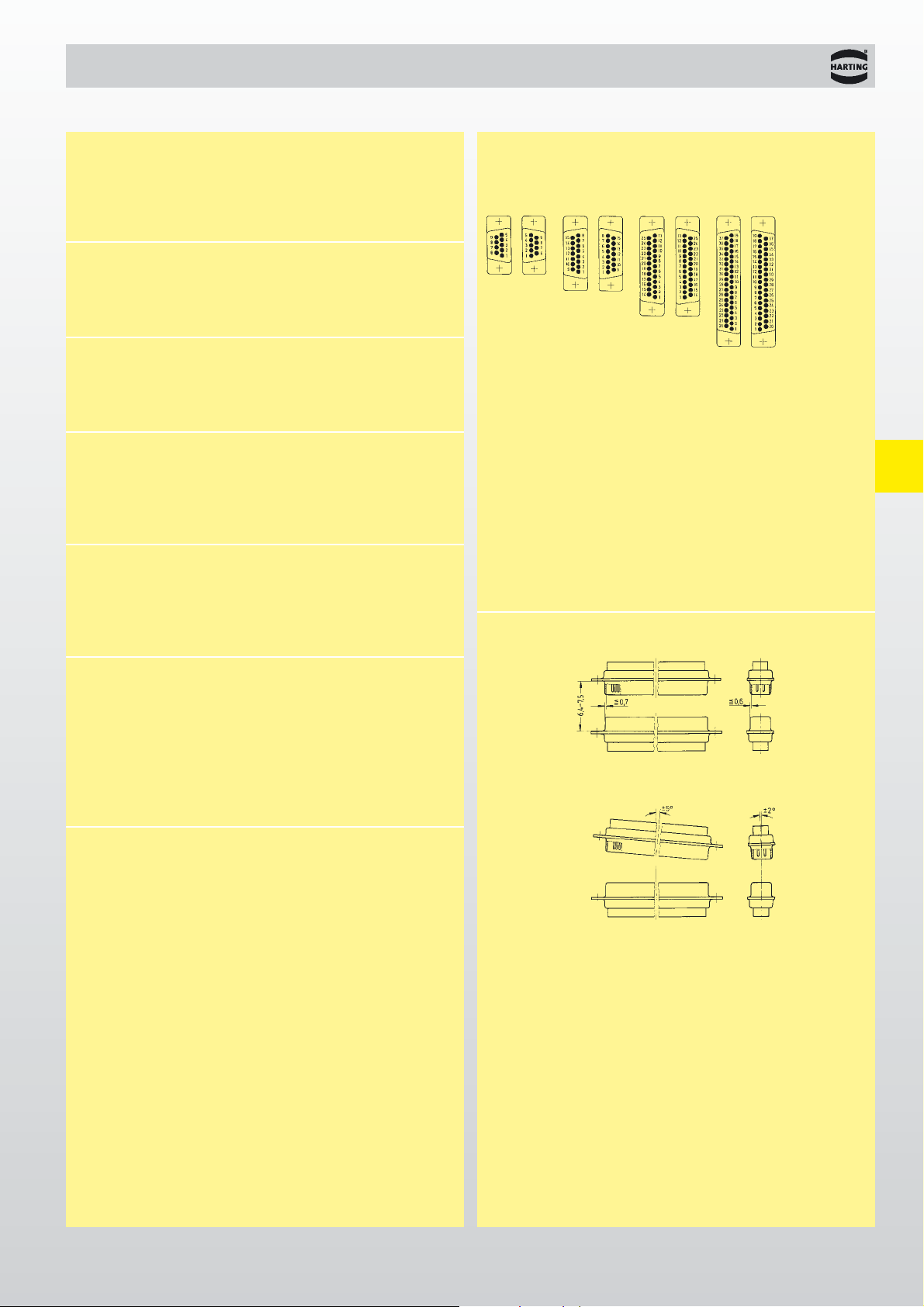
Contact arrangement
View from termination side
Mating conditions as per CECC 75301
M = Male connector
F = Female connector
Number of contacts 9, 15, 25, 37
UL recognized
Working current 7.5 A max.
Test voltage U
r.m.s.
1 kV
Contact resistance ≤ 10 mΩ
Insulation resistance ≥ 1000 MΩ
Temperature range -55
O
C … + 125 OC
Heat deflection temperature + 255
O
C
limit according to DIN 53 461
Terminations a) Solder buckets max. 0.8 mm²
b) Solder pins Ø 0.6 mm for
P.C.B. holes Ø 0.8/1 mm
c) Solder pins, angled 90
O
Ø 0.6 mm for P.C.B. holes
Ø 0.8/1 mm
Materials
Insulation PCT, glass-fibre filled,
flame retardant acc. to
UL 94-V0
Colour: natural
Contacts Copper alloy
Male and female contacts
are turned
Contact surface
Contact zone Selectively plated according
to performance level
Performance level Performance level 2, as per
CECC 75 301-802,
250 mating cycles,
4 days 4 mixed gas test –
IEC 60 512
Metal shell Steel
37 way
9 way
15 way
25 way
Page 2

D-Sub - F
05
.
04
D-Sub
1 5 10 50 100 500 1000
30 35
111163532
1 3 12 24 38 30
1 6 11 25 35 38 32
47
470
1000
3900
Min. insertion loss
1)
Capacitance tolerance = ± 20 % (For other capacitor values see pages 05.30 ff).
Measured in 50 Ω system according to MIL-STD-220, no load.
Working voltage: 100 V max for standard capacitance values – higher working
voltages are available as specific.
Dielectric withstanding voltage: 250 V DC max. – higher dielectric withstanding voltages are
available as specific (see page 05.30)
Insertion loss [dB]
Frequency [MHz]
Typical insertion loss for different filters (measured)
Attenuation characteristics for standard capacitance values
Capacitance [pF]
1)
Frequency [MHz]
Attenuation (in dB) vs. frequency [MHz]
Page 3

D-Sub - F
05
.
16
9 09 64 124 721 . 09 64 114 721 .
15 09 64 224 721 . 09 64 214 721 .
25 09 64 324 721 . 09 64 314 721 .
37 09 64 424 721 . 09 64 414 721 .
9 09 64 124 722 . 09 64 114 722 .
15 09 64 224 722 . 09 64 214 722 .
25 09 64 324 722 . 09 64 314 722 .
37 09 64 424 722 . 09 64 414 722 .
9 09 64 124 723 . 09 64 114 723 .
15 09 64 224 723 . 09 64 214 723 .
25 09 64 324 723 . 09 64 314 723 .
37 09 64 424 723 . 09 64 414 723 .
9 09 64 124 724 . 09 64 114 724 .
15 09 64 224 724 . 09 64 214 724 .
25 09 64 324 724 . 09 64 314 724 .
37 09 64 424 724 . 09 64 414 724 .
D-Sub
4-40 UNCþ2
M3
þ
3
male connectors female connectors
No. of
Identification contacts Part No.
Connectors with
47 pF C filter
Connectors with
470 pF C filter
Connectors with
1000 pF C filter
Connectors with
3900 pF C filter
Turned solder pins, right angled, bracket, board lock and clinch nut
Number of contacts
9--37
Please insert digit
for flange thread
Page 4

D-Sub - F
05
.
17
D-Sub
Board drillings
Male connector
Female connector
Identification Drawing Dimensions in mm
Turned solder pins, right angled, bracket, board lock and clinch nut
Number of contacts
9--37
No. of
AB
1
B
2
CEF
contacts
9 30.8 16.9 16.4 25.00 1.37 2.74
15 39.1 25.2 24.7 33.30 1.37 2.74
25 53.0 38.9 38.5 47.04 1.40 2.77
37 69.3 55.3 54.9 63.50 1.40 2.77
 Loading...