


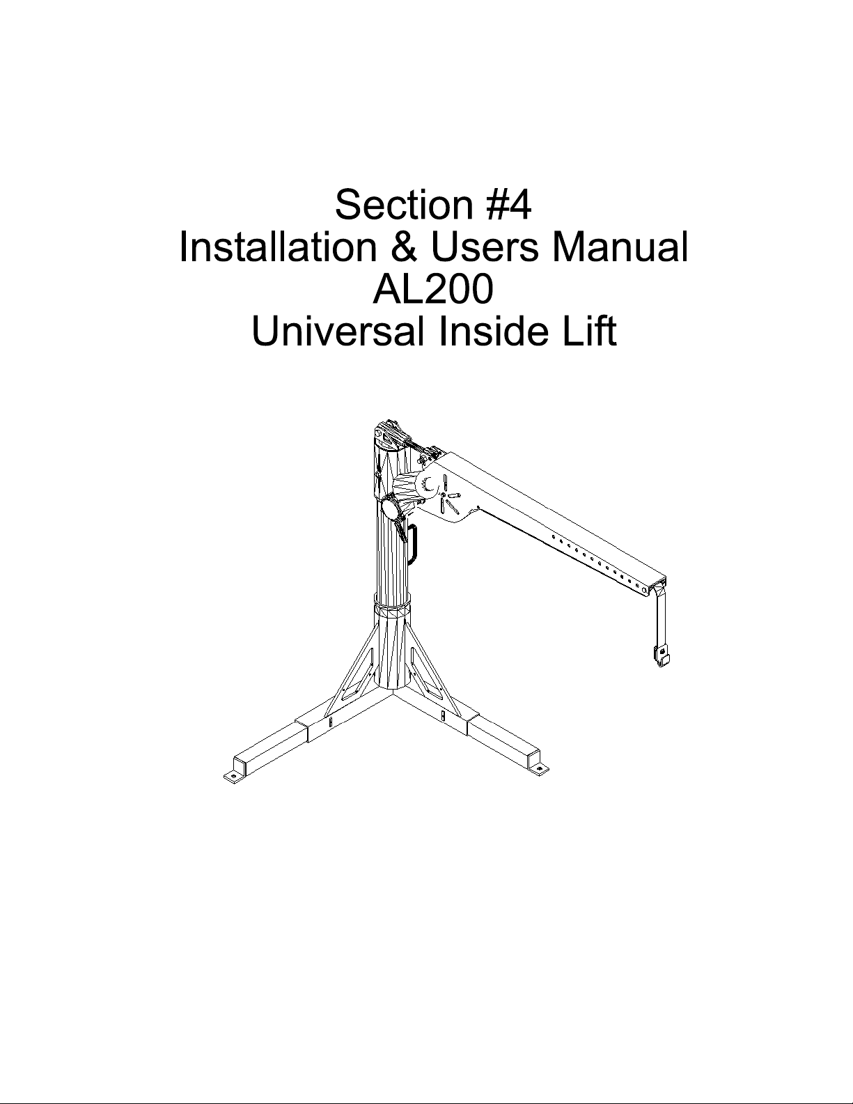
AL400

Inside Style Lift
AL200 / AL400 / AL055
Installation Guide & Owners Manual
AL200 Manual Rotation Lift AL400 Fully Powered Lift AL055 Economy Lift
Congratulations on your new lift purchase. The Universal Inside Lift line is one of the easiest and most trouble free
ways to transport your scooter or power chair. This manual is written to be used both as an installation guide as well
as an operation guide for the end user. Please read the manual thoroughly BEFORE attempting any installation, adjustment or use of the lift.
Both installers and operators should familiarize themselves with this entire manual.
The manual will be divided into the following sections for easy reference;
Section 1 - Unpacking the Lift
Section 2 - Vehicle Preparation
Section 3 - Wiring the Vehicle
Section 4 - AL200 Installation & Operation
Section 5 - AL400 Installation & Operation
Section 6 - AL055 Installation & Operation
Section 7 - Safety & Maintenance
If you have any questions or comments concerning the installation or operation of your scooter lift, please contact
your local distributor for additional technical information. Only authorized dealers should install this lift.
Caution: Some scooters and power chairs may be unsuitable for transport in or on a motor
vehicle. Please contact the manufacturer of your mobility device to determine its transportability.
1
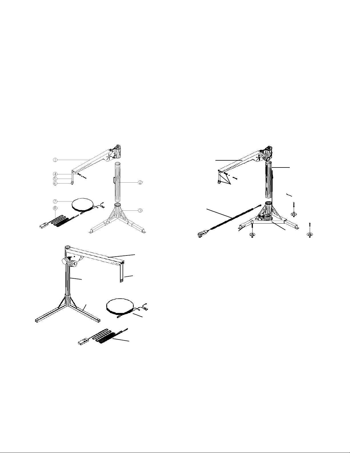
Section 1 - Unpacking the Lift
Your Fully Powered Inside Lift was factory pre-assembled to require little assembly before installation.
AL200 / AL400 Box contents should include:
Package Check List Hardware Package
Lifting Arm (# 1) Contents include:
Standard Post (# 2) Vehicle Wiring Harness (# 7)
Base (# 3) Hand Control (#8)
Strap & Hook Assembly (# 4,5,6) 3 - Installation Washers
Leg Extensions (#9) Required Fasteners
Black zip ties
Figure 1.1 Figure 1.2
AL200 Universal Inside Lift AL400 Fully Powered Lift
1
2
4,5,6
8
9
3
#1
Figure 1.3
AL055 Economy Lift
Package Check List Hardware Package
Lifting Arm (# 1) Contents include:
#2
#4,5,6
Post (# 2) Vehicle Wiring Harness (# 7)
Base (# 3) Switch Harness (#8)
Strap & Hook Assembly 3 - Installation Washers
#3
(# 4,5,6) Required Fasteners
Black zip ties
#7
#8
Be sure and check the contents of the box against the package check list to be sure that all parts are included with
the lift that are required for proper installation. If any parts are missing or if any damage is noted, immediately contact
the distributor from which you purchased your lift. DO NOT attempt to install or use the lift with any missing or damaged parts.
2

Section 2 - Vehicle Preparation
The Inside Lift has been designed with the shortest height and smallest footprint requirements to allow maximum
room for the loading and unloading of your scooter or power chair. If there is 30” of headroom and room for the
scooter or chair in the vehicle, then our lift should be able to be installed and operate properly. (The AL055 requires
37” of headroom unless the post is cut for smaller openings)
• To obtain the ideal mounting location and avoid possible interference, the lift should be pre-assembled and “trial
fit” in the desired installation location. This procedure may require two people, one person to hold the lift in the
desired position and another to move the Lifting Arm through its full range of motion. Please refer to Figure
#1.1—1.3 for the parts identification and exploded view of the lift. The Inside Lifts have been engineered so that
it can easily be configured as a solution for most applications. This “trial fit” will also help you determine where
the Vehicle Wiring Harness will be run.
Hint: It is always best to check with the customer when determining lift placement and ask permission before drilling
through the vehicle’s floor.
• Typical Applications Car Trunk—AL200 and AL055 only
Rear Cargo Area—for most vans and SUV’s.
Side Door—for use on either side door of a van.
Tailgate applications for SUV’s, Station Wagons and Trucks using
the offset arm conversion option. (Except AL055)
NOTE: The base should be mounted as far to the rear corner of the vehicle as possible in most rear mount applications. This allows for the maximum reach of the lifting arm.
There are some vehicles that, due to their setup, will not accommodate a standard lift installation. Please check for
the following:
• Vehicle must have 30” clear headroom
for operation. Be sure and check during “trial fit” that a full range of mo-
tion can be achieved without any roof or lift gate interference. (37” headroom required for AL055)
• Spare tire storage—Some vehicles store the spare tire under the floor of the vehicle. Make sure that the base
can be bolted through to a steel floor or frame.
• Some vehicles have been manufactured with a “false floor” which is made of composite materials. The lift must
be anchored to a steel floor or frame.
• Trunk applications must be secured to a flat trunk floor. (AL200 and AL055 only) Make sure that there are not
deep wells in the trunk that will affect placement of the base. Most of these can be overcome.
• Offset Arm Applications (Except AL055) - The offset arm allows the lifting arm to reach around to the side of the
vehicle. This allows the loading and unloading of the scooter or power chair when there is a tailgate to contend
with or when the base location does not allow a straight post to be used. Many times this application is referred
to as a “curbside” installation. (See Figure #4.2 or #5.3)
Trial Fit Procedure:
• Place the assembled lift as it is configured in the shipping carton into the desired location.
When using the Offset Post Conversion, bolt the Lifting Arm to the Post using the supplied 3-3/4” Hex bolt
and lock nut. The offset arm can be configured to left side or right side applications by bolting the Lifting Arm
to the Offset Post in either orientation.
• Raise the Lifting Arm to achieve to an 1/8” clearance to the lowest point of the vehicle’s roof that the Lifting Arm
will encounter during its travel (usually the door opening or rear A/C vents).
• On the AL200 and AL400, unscrew the Adjustable Link to provide the desired height of the Lifting Arm and bolt
the two components together using the supplied 3/8” x 2” hex bolt, washers and 3/8” Stover lock nut—no nylon.
• Mark the desired position for installation including the power wire and proceed to the wiring Section #3.
3
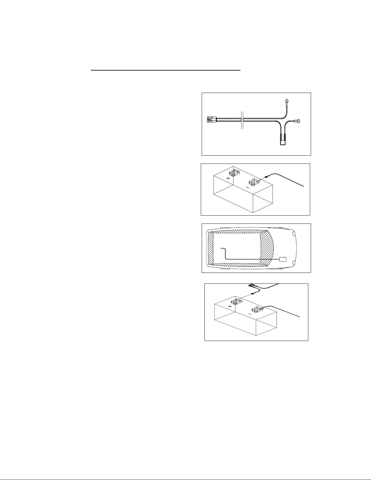
Installing the Vehicle Wiring Harness
Important Note: IMPROPER WIRING IS THE #1 CAUSE OF PROBLEMS IN THE OPERATION OF
A VEHICLE LIFT. FOLLOW THE WIRING INSTRUCTIONS CAREFULLY
Located in the hardware package is the vehicle wiring harness. The harness is manufactured to, and
complies with the SAE J1128 requirements. The wire harness is approximately 23 ft. long and will accommodate
most vehicles.
1. Unwind the harness and lay it flat. One end of the
harness has a black plug . This is the lift end of the
harness and goes to the back of the vehicle.
2. Begin routing the wiring harness at the vehicle
battery. Attach the black wire to the negative
terminal on the battery. Do not attach the red wire
yet.
3. Run the wiring harness under or when possible
through the vehicle, back to the lift. If you need to
pass the wiring through a fire wall or hole in the
vehicle you may cut the double wire and reassem-
ble it with butt connectors. Always locate the wiring
harness where it can not be snagged by road de-
bris and away from the vehicles gas tank.
4. If the harness is too long for the vehicle, coil the
excess wire and secure it to the vehicle frame with
the supplied tie wraps.
5. Attach the red wire to the positive terminal on the
battery.
Important Reminder: Never attempt to attach the wire harness to a secondary power source,
The lift requires direct connection to the battery.
Caution: When the installation requires the wiring harness be run on the underside of a
vehicle, route the harness away from the exhaust system, brake lines, fuel lines, gas tank,
pinch points, and sharp edges. Locate the wiring harness where it can not be snagged by
road debris.
Manufactures Recommendation: Schedule a routine maintenance visit with the end user. Harmar recommends the lift be greased in the applicable areas, and the wire harness connections be checked for corrosion, and/or decay, as such conditions are normal due to environ-
4
5

Section 4 - Installing the AL200 Lift
• You should have established a mounting position for the lift during the “trial fit” as described in Section #2 of this
manual. If not, it is recommended that you go through that procedure.
• Mount the lift in the location determined during the “trial fit” in the vehicle. The Leg Extensions in the Base telescope in and out to avoid potential obstacles. For heavy application, pull the Leg Extensions out as far as is
practical for increased base stability. Mark the 3 mounting hole locations or use the Base as a guide and drill
holes using a 3/8” drill bit. Bolt the Base to the floor of the vehicle using the supplied 3/8” x 3” hex bolt in the corner, two 3/8” x 2” hex bolts for each Leg. Use the supplied multi-hole Installation Washers on the underside to
help reinforce the vehicle’s floor, see Figure #4.1. Replace an Installation Washer with a 3/8” fender washer if
necessary due to size constraints. Secure the Telescoping Legs by tightening the 2 set screws on the inside of
the base. Hint: Variations in the flatness of the vehicle’s floor can be compensated for by adding 3/8” washers to
the mounting hardware under the base. Always mount the base so it is level.
Caution! If the set screws on the base do not contact the Leg Extensions, they are telescoped out too far
and must be moved into the Base further.
Caution! Avoid the vehicle wiring, fuel lines, fuel tanks, spare tires, etc. when drilling holes for mounting
hardware!
• The Hand Control has two plugs on it. One, the male plug, attaches to the Vehicle Wiring Harness that was installed earlier. The other, the female plug, attaches to the motor on the lifting arm. At this time, reconnect the
vehicle’s ground (-) cable on the battery.
• Tie the long leads of the Hand Control Harness to the Post using the plastic ties where necessary. This step will
be skipped when using the lift in a “Take Apart” configuration, as the Lifting Arm and the Post must be disassembled.
• Follow the Operator Instructions in Section #5 to Load and Unload the scooter of chair from the vehicle to test
operation and clearances.
• Determine if the scooter or chair will need to be moved closer to the lift or further from the side of the vehicle.
This will be done by adjusting the location of the Strap Roller on the Lifting Arm. The Lifting Arm is factory preassembled with the strap out at the furthest extent and may need to be adjusted to fit a particular application.
• Measure the distance the scooter should be moved to clear any obstacles.
• To move the Strap Roller, remove the Split Ring (like on a key chain) from the Clevis Pin. Pull out the Clevis Pin
and Strap Roller and replace it in the desired hole location. Holes on the Lifting Arm are on one inch centers.
• Recheck all fasteners.
Refer to the instructions included with your docking device for information on preparing the scooter or power chair for
use with the Universal Inside Lift.
Figure #4.1 Figure #4.2 Figure #4.3
Installation of Base Offset Post Option Adjustable strap on Lifting Arm
6

Section 4 - Operating the AL200 Lift
Trunk Applications:
Operational Guidelines:
• Inspect the Lifting Strap prior to each use. Contact your distributor if it shows signs of wear or fraying.
• Do not operate this lift until you dealer has satisfactorily instructed you in the proper operation of this lift.
• Always make sure the vehicle’s parking brake is firmly set before operation.
• Keep hands and feet from under the scooter or power chair as it is being lifted.
• Take care not to hold one of the buttons on the Hand Controller until the Lifting Strap switches direction. The UP
button should always pull the strap up and vice versa. If your buttons cause opposite movement, contact your
distributor.
Loading your Scooter or Power Chair —Trunk Applications
Note: Due to the wide variety of scooters, power chairs and vehicles, your dealer may offer a different method for
Loading and Unloading your scooter. Please follow the guidelines they have offered.
• To assemble your lift, begin by inserting the Post into the Base mounted on the floor. Next, slide the Lifting Arm
onto the top of the Post.
• Plug the Hand Control into the lifting arm and into the Vehicle Harness.
• Swing the Lifting Arm out of the vehicle toward the scooter.
• Maneuver the scooter parallel to the rear bumper and two inches behind the vehicle. Depending on the vehicle, it
may be necessary to: remove the seat; fold down or remove the handle bar; remove accessories such as brackets, baskets, crutch holders, etc.
• With the docking device positioned directly under the Strap Hook, lower the Lifting Strap using the DOWN button
on the Hand Control until the Strap Hook can be engaged into the docking device installed on the scooter or
chair. Hook the docking device on the scooter or chair with the Strap Hook and remove any play in the strap by
pushing the UP button on the Hand Control until tension is felt.
Caution: Ensure that the Lifting Strap is secure and taught and that it points straight down. Failure to do so
could result in the scooter or chair swinging toward the operator of the vehicle.
• Raise the scooter or chair using the UP button until the scooter or chair is just above the trunk lip.
Caution: Stop lifting before the Strap Hook contacts the Strap Roller mounted on the Lifting Arm. Contact
will result in damage to the lift. A properly adjusted and operated lift will avoid this.
• Swing the scooter or chair into the vehicle, ensuring that the scooter or chair does not contact the vehicle.
• With the scooter or chair positioned above its stowed position, lower the lift using the DOWN button on the Hand
Controller. Continue lowing the Strap Hook slightly beyond the scooter touching the floor to allow removal of the
Strap Hook from the Docking Device on the scooter or chair.
• To disassemble the lift, first raise the strap until the freed Strap Hook is about an inch away from the Lifting Arm.
Unplug the Hand Control harness from both the Vehicle Harness and the Lifting Arm.
• Pull the Lifting Arm off the Post and lay it on the floor of the trunk. Then, pull the Post out of the Base using the
handle and set it down with the Lifting Arm.
7

Section 4 - Operating the AL200 Lift continued
Trunk Applications
• If preparations needed to be made to secure the scooter or chair for transport, such as parking brakes or wheel
chocks, do these now. Dealers should instruct operators on how, if necessary, to secure the scooter or chair for
transport. Close the trunk and you are ready to go.
Unloading Your Scooter or Power Chair —Trunk Applications
• Undo any preparations made to secure the scooter or power chair for transport.
• To assemble your lift, begin by inserting the Post into the Base mounted on the floor. Next, slide the Lifting Arm
onto the Post.
• Plug in the Hand Control.
• By pressing the DOWN button on the Hand Control harness, run the Strap Hook down until it is slightly lower
than the docking device on the scooter.
• Attach the Strap Hook to the docking device on the scooter or chair and remove any play in the strap by pressing
the UP button on the Hand Control until tension is felt.
Caution: Ensure that the Lifting Strap is secure and taught and that it points straight down. Failure to do so
could result in the scooter or chair swinging toward the vehicle or operator.
• Raise the scooter or power chair using the UP button until the scooter or chair is just above the trunk lip.
Caution: Stop lifting before the Strap Hook contacts the Strap Roller mounted on the Lifting Arm. Contact
will result in damage to the lift. A properly adjusted and operated lift will avoid this.
• Swing the scooter or chair out of the vehicle, carefully ensuring that the scooter does not contact the vehicle.
• With the scooter or chair positioned away from the vehicle, lower the lift using the DOWN button. Continue low-
ering the lift slightly beyond the scooter or chair touching the ground to allow removal of the Strap Hook from the
docking device on the scooter.
• To disassemble the lift, first raise the Lifting Strap until the freed Strap Hook is about an inch away from the Lifting Arm. Unplug the Hand Control harness from both the Vehicle Harness and the Lifting Arm.
• Pull the Lifting Arm off of the Post and lay it on the floor of the trunk. Then pull the Post out of the Base using the
handle and set it down with the Lifting Arm.
Replace anything removed from the scooter or chair for loading purposes. Close the trunk and you are ready to go.
8
 Loading...