

Page 1
TY
TY
I
I
L
L
I
I
OB
OB
M
M
Y
T
I
L
I
B
O
M
Y
T
I
L
I
OB
M
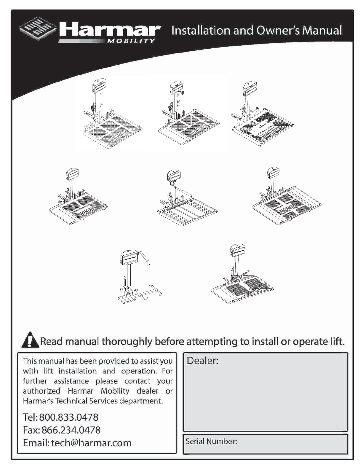
AL500 Universal Power Chair Lift
Capacity: 350 lbs Capacity: 350 lbs Capacity: 350 lbs
TY
I
L
I
B
O
M
AL300 Universal Power Chair /
Scooter Lift
Capacity: 350 lbs
AL 560 Auto Hold Down P.C. Lift
ITY
L
I
B
O
M
AL030 Power Tote for
Manual Wheelchairs
Capacity: 100 lbs
AL100 Universal Scooter Lift AL550 Automatic Power Chair Lift
Y
T
LI
I
B
O
Y
IT
IL
B
O
M
Outside Lift
Capacity: 350 lbs
AL301XL Extra Wide Power Chair /
Y
T
I
IL
B
O
M
AL010/050 Micro Power Chair /
Micro Scooter Lift
Capacity: 135 lbs
M
Scooter Lift
Capacity: 350 lbs
1
Page 2
Unpacking the Lift
1 1
1
1
2
2
2
2
3
3
3
3
4
4
5
11
2
3
11
2
3
4
AL500
Package Check List Package Check List
Main lift body (# 1) Main lift body (# 1)
Hitch Post (# 2)
Hitch Adapter (# 3)
Anchor Plate
Hardware pack
AL100
Hitch Post (# 2)
Hitch Adapter (# 3)
Hardware pack
Spreader Bar (# 4)
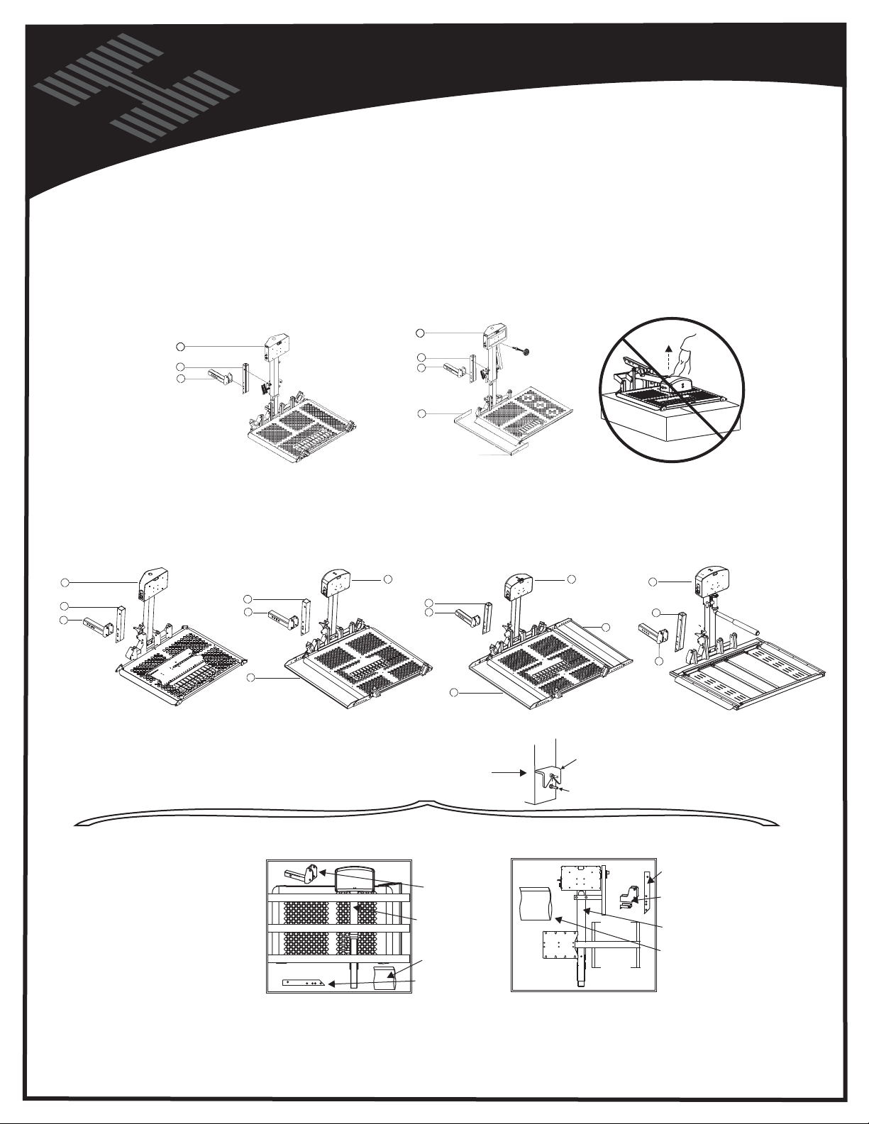
UNPACKING THE LIFT
Your Universal Outside Lift was factory preassembled to require little assembly before installation.
Box contents should include:
Hardware Package
Contents Include:
Vehicle Wiring Harness
Required Fasteners
Keys
Black tie wraps
Instruction Manual
DO NOT
LIFT
FROM
MOTOR
COVER
AL550
Package Check List
Main lift body (#1)
Hitch Post (#2)
Hitch Adapter (#3)
Hardware pack
THE AL010/050’s PLATFORM
HAS BEEN LEFT OFF
FOR A DECREASE IN PACKAGE
SIZE, ALLOWING NEXT DAY
SERVICE / NON-FREIGHT
SHIPPING. ATTACH TO LIFT
AT PIVOT BOLT (SEE
EXPLODED VIEW FOR
REFERENCE )
AL300
Package Check List
Main lift body (# 1)
Hitch Post (# 2)
Hitch Adapter (# 3)
Spreader Bar (# 4)
Hardware pack
Hardware pack
NOTE: THE PLATFORM WILL NOT
UNFOLD UNTIL THE LIFT HAS BEEN
LOWERED AT LEAST AN INCH
AL010/050 - Micro Scooter / Power Chair Lift
AL301XL
Package Check List
Main lift body (# 1)
Hitch Post (# 2)
Hitch Adapter (# 3)
Rear Wheel Craddle (# 4)
Front Wheel Craddle (# 5)
CLASS 2
Hitch Adapter
LIFT BODY
HARDWARE
PACK
HITCH POST
Hardware pack
LIFT
PLATFORM
KEEPER
WELDE
D TO
P
LATF
OR
M
AL030 - Manual Wheelchair Lift
Al560
Package Check List
Main lift body (# 1)
Hitch Post (# 2)
Hitch Adapter (# 3)
HITCH POST
HITCH ADAPTER
and Stabilizer
LIFT BODY
HARDWARE PACK
Be sure and check the contents of the box against the package check list to be sure that all parts are included with
the lift that are required for proper installation. If any parts are missing or if any damage is noted, immediately contact
the distributor from which you purchased your lift. DO NOT attempt to install or use the lift with any missing or
damaged parts.
2
Page 3
WIRING THE VEHICLE
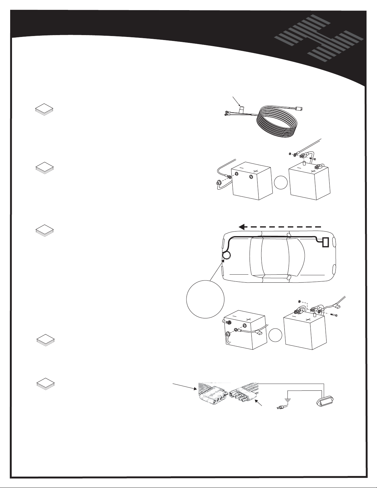
Vehicle Wiring Harness
Installation Instructions
1
Unwind the harness and lay it flat. One end of the
harness has a black plug . This end of the harness
goes to the back of the vehicle.
2
BEGIN ROUTING THE VEHICLE
HARNESS AT THE BATTERY
Attach the black wire to the negative terminal on the battery.
Do not attach the red wire yet.
Self-resetting
Circuit Breaker
To vehicle's
battery
BLACK WIRE
OR
To back
of vehicle
BLACK WIRE
Run the wiring harness under, or when possible through
3
the vehicle, back to the trailer hitch. Always locate the wiring
harness where it can not be snagged by road debris and
away from the vehicle's gas tank.
If the harness is too long for the vehicle, coil the
excess wire and secure it to the vehicle frame with
cable ties.
Secure the plug about even with the end of
the hitch receiver tube.
Do not cut or shorten the harness.
COIL
EXCESS
WIRE
HERE
4
Attach the red wire to the positive terminal on the battery.
Wire in a Standard 4-contact female flat trailer
5
connector to the vehicles' taillights. This will
provide power for the motor cover light.
Important Reminder: Never attempt to attach the wire harness
to a secondary power source. The harness requires direct connection
to the battery.
Side mount
RED WIRE
Side mount
TRAILER PLUG
ON LIFT HARNESS
OR
BROWN WIRE
Ground for light is
provided by main
2 prong power
connector
Top mount
Top mount
MOTOR COVER
RED WIRE
LIGHT
Caution: Route the harness away from the exhaust system, brake lines, fuel lines, gas tank, pinch points,
and sharp edges. Locate the wiring harness where it can not be snagged by road debris.
3
Page 4
Vehicle Hitch
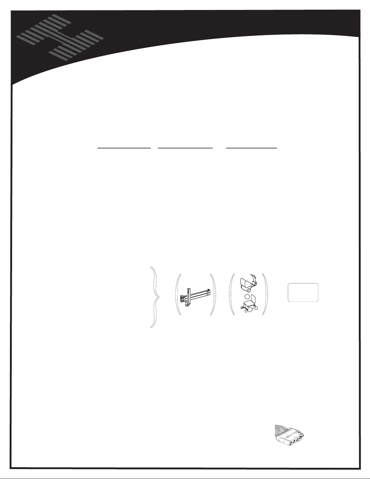
To install an Outside Lift on a vehicle, the vehicle must be capable of accepting a Class 2 or Class 3
hitch. If you are unsure about the vehicle and hitch compatibility, contact a local hitch installer or the
web sites below. The vehicle should also be wired with standard 4 post trailer wiring.
Listed below are three websites of hitch companies that can be used as a reference
www.hitch-web.com
, www.reeseprod.com, or
VEHICLE HITCH
www.draw-tite.com
Be sure to recommend a hitch installer that is reputable, insur
direct reflection on the customers perception of a properly installed mobility lift.
Impor
tant Note: Not every vehicle is capable of having a hitch installed
Remember: Calculate the weights of the lift, mobility d
option, being certain that the total weight does not exceed the recommended tongue weight of the
hitch. Different types of hitches are capable of bearing different amount of tongue weight.
The lift manufacturer suggests the installer observe the vehicles Gross Vehicle Weight Ratings and
Restrictions.
HITCH
PRODUCT:
AL 100
AL 500
AL 550
AL 300
AL 301XL
AL 010/050
AL 030
AL 560
CLASS:
2 or 3
2 or 3
2 or 3
2 or 3
2 or 3
2 or 3
1, 2 or 3
2 or 3
WEIGHT:
98 lbs
95
lbs
112
lbs
127
lbs
110
lbs
73
lbs
60
lbs
lbs
105
+
IF
USED
Not for
AL030
Swing
40 lbs
ed, and capable, as their work has a
evice, and where applicable the swing away
Chair /
Away
+
Scooter
OR
X lbs
Must NOT
Exceed Hitch
=
Manufacturer's
Max Tongue
Weight
lbs
Important Note: Some states have very strict license plate obstruction laws, so be sure to familiarize
yourself with the local and state laws.
Important Note: Assure the receiver tube of the hitch is parallel to the ground. This is not a
recommendation, but rather a requirement.
If the hitch is not installed properly, it will affect the functioning of the lift.
Some vehicles will require that the rear suspension be supplemented. The manufacturer
recommends the installer contact a suspension specialist for additional technical support.
A vehicle with a Class 3 (Class 2
wiring is ready for installation of the lift.
requires optional accessories) hitch and standard 4 post trailer
4
Page 5
VEHICLE HITCH
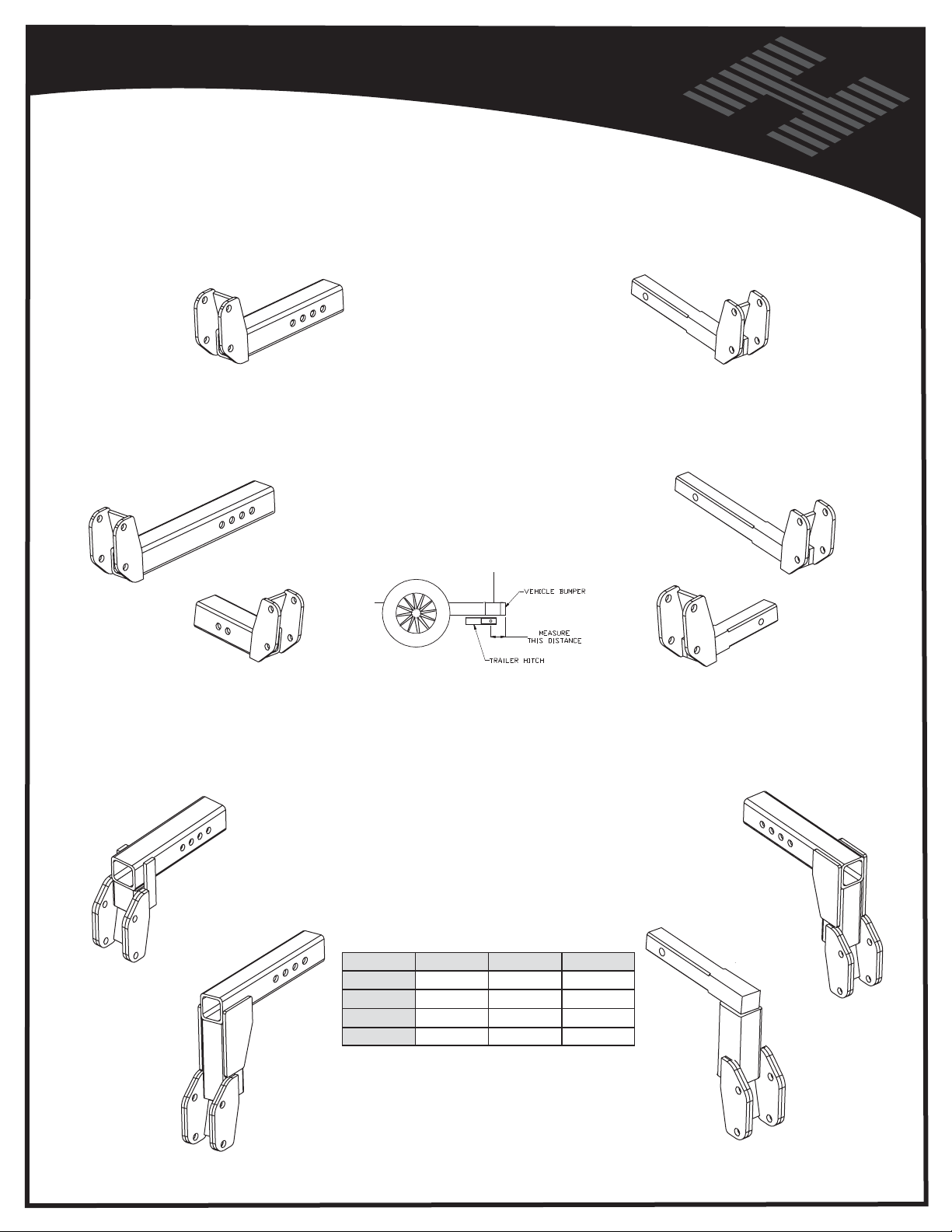
Hitch Adapters
AL123
Standard Class 3
AL125
Class 3 Extra long
H124
Class 3 Short
AL1232
2in Drop Class 3
A Hitch Adapter is the part of the lift
that plugs into a vehicle's trailer hitch.
Several hitch adapters are available
to fit the needs of differnet vehicles.
When selcting a Hitch Adapter you
should determine the hitch class and
measure the bumper distance.
Bumper distance is the length from the
trailer hitch's bolt hole to the rear most
point on the vehicle.
Hitch class is usually printed on the trailer hitch,
however it can also be determined by measuring
the inside of the receiver on the trailer hitch.
Class 2 hitches measure 1-1/4" x 1-1/4"
Class 3 hitches measure 2" x 2"
Once you have determined the hitch class
and bumper distance, refer to the diagram
below to select the proper hitch adapter.
As always, Harmar Mobility's trained personnel
will be glad to assist you in selecting the
proper hitch adapter.
AL126
Standard Class 2
AL127
Class 2 Extra long
H128
Class 2 Short
AL1235
5in Drop Class 3
AL1236
6in Drop Class 3
Hitch Class Bumper Distance Bumper Distance Bumper Distance
Class II 0”-7.5” 7.5”-10” 10”-13.5”
AL126 AL127
Class III AL123 AL125 AL125
AL1265
4in Drop Class 2
Shorter adapters available for
shallow hitches.
Drop adapters available for higher
than normal vehicles.
5
Page 6
Vehicle Hitch
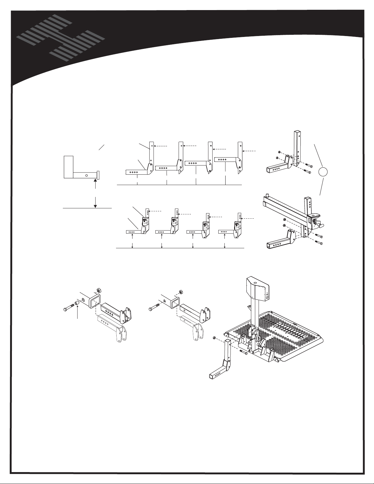
In order to determine how to assemble the Hitch Post and Hitch Adapter, the distance from the
bottom of the hitch to the ground must be measured.
together the Hitch Post and Hitch Adapter. Use the 1/2” x
Drawings below depict a Class 3 Hitch Adapter
The installation for a Class 2 is identical
HITCH
POST
INSTALLATION
Determine which set of holes to use to bolt
3-1/2” bolts and nuts provided and tighten.
Hitch
Post
Without Swing
Away Option
Measure from
Hitch Bar to ground
With Swing
Away Option
HITCH
ADAPTER
5-13"
SWING AWAY
HITCH
ADAPTER
4-12" 12-14"
13-15"
15-17"
14-16"
17-19"
16-17"
Once you have determined the proper adjustment for the Hitch Post or Swing Away
and have attached it to the Hitch Adapter, insert the adapter into the hitch receiver
and attach it using the 1/2" x 3-1/2" bolt, , Pinch Bolt Tube and lock nut.
CLASS 3
( 2 x 2 TUBE )
PINCH BOLT
TUBE
OR
CLASS 2
( 1.25 x 1.25 Solid Bar )
Pinch Bolt Tube
Not required, as
Class 2 is threaded
OR
OR
Swing
Away
NOTE: Pinch Bolt Tube is added to the Class 3 reciever
bolt to prevent the lift from moving side to side
Extremely Important Note:
Attach Lift to Hitch Post or Swing Away
DO NOT OVERTIGHTEN THIS BOLT!
It is a pivot point!
Valuable Installation Hint! (Using Caution), Once the lift is placed behind the vehicle, plug the
power cord into the harness that you have installed on the vehicle. Turn the key on an
toggle DOWN switch to raise the motor box. Continue to power the lift until the mounting holes in the
lift are even with the top hole in the Hitch Post. Attach the lift to the post using the supplied 1/2” bolt
with lock nut and washers. Using this method will allow you to attach the lift without physically having
to lift the unit and hold it while the bolt is inserted.
Route the lift power cord down the lift away from its moving parts and potential pinch points. The
cord should follow along the post and be secured with zip ties provided to allow the lift to operate
without disconnecting the power cord.
6
d use the
Page 7
INSTALLATION
Bumper Mount
( Be sure to comply with
vehicle's bumper rating )
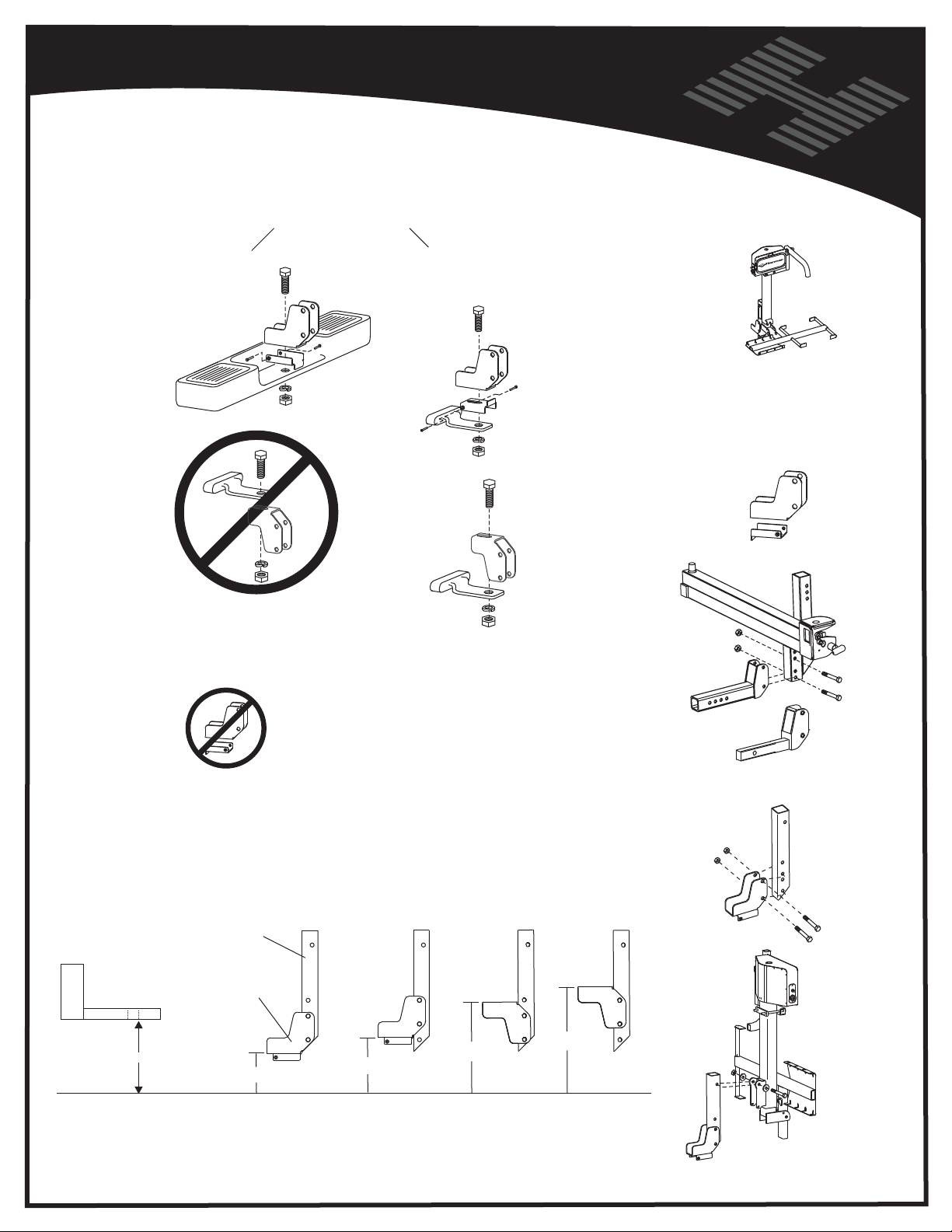
FOR AL030 ONLY
( Ball Mount
Hitch adapter )
Flat Bar Style
( Be sure to comply with
vehicle's bumper rating )
Y
T
I
L
I
B
O
M
For AL030 ONLY
Ball Mount Hitch
Adapter and
stabilizer
Do not attempt to
mount up from under
Ball Mount Hitch Adapter
can NOT be used when
installing a Swing Away
Drawings below depict a Ball Mount Hitch Adapter
The installation for a Class 2 or 3 Hitch
Adapter can be used and is identical
HITCH
POST
BALL MOUNT
HITCH
ADAPTER
Omit stabilizer
OMIT
STABILIZER
Only Class 3 or 2
Hitch Adapters
can be used with
a Swing Away
OMIT
STABILIZER
Swing
Away
OR
Measure from Hitch Bar to ground
5-13"
13-15"
15-17"
7
17-19"
Page 8
Vehicle Hitch
AL600 & AL690
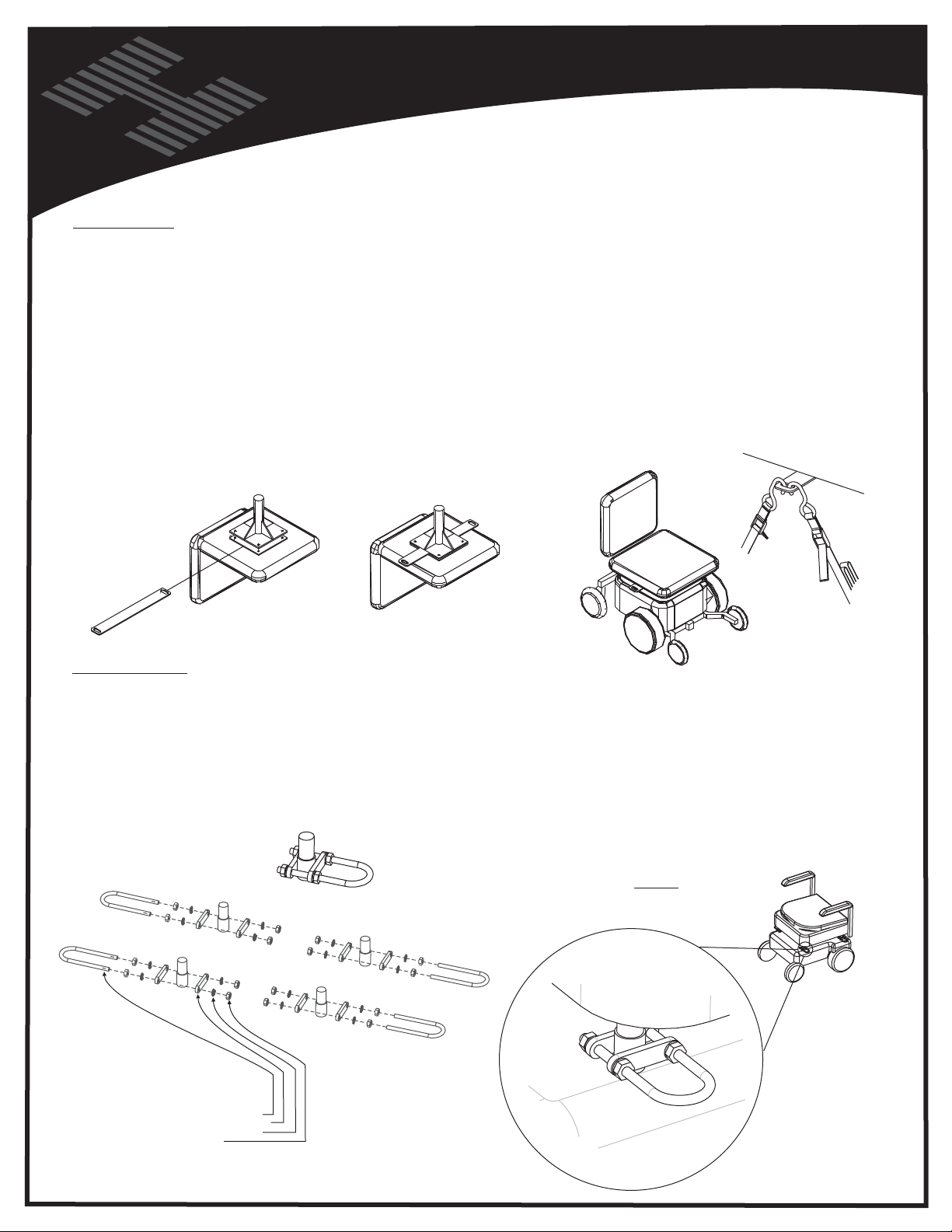
ANCHOR PLATE:
THE ANCHOR PLATE IS A FLAT PLATE THAT IS 20” LONG WITH A SLOT IN EACH END.
THIS PLATE WILL WORK WITH ANY CHAIR OR SCOOTER THAT HAS A CENTER SEAT POST
AND ATTACHES TO THE BOTTOM OF THE SEAT.
ATTACH THE ANCHOR PLATE BY THE FOLLOWING STEPS:
THE ANCHOR PLATE SHOULD EXTEND ABOUT 1-1/2” OUT FROM THE SIDE OF THE CUSHION.
THIS WILL ALLOW THE USER TO ATTACH THE STRAP HOOKS TO THE ANCHOR PLATE TO SECURE
THE CHAIR TO THE LIFT.
1. REMOVE SEAT FROM THE CHAIR.
2. LOOSEN THE SCREWS THAT ATTACH THE PLATE TO THE BOTTOM OF THE SEAT. ALLOW ENOUGH ROOM
TO SLIDE THE ANCHOR PLATE BETWEEN THE SEAT AND SEAT PLATE.
3. ATTACH THE ANCHOR PLATE IN THE CENTER OF THE SEAT PLATE WITH THE HOLES ON EACH END
EXTENDING EVENLY ON EACH SIDE OF THE SEAT.
4. RE-TIGHTEN THE SCREWS THAT HOLD THE SEAT PLATE TO THE BOTTOM OF THE SEAT.
5. REPLACE THE SEAT ON THE CHAIR.
Power Chair or Scooter
CHAIR PREPARATION
Preparation
THERE ARE 2 OPTIONS ON HOW TO ATTACH
THE STRAP HOOKS TO THE CHAIR
THAT ARE INCLUDED WITH THE LIFT.
ANCHOR U-BOLTS:
THE U-BOLTS ARE TO BE USED WITH POWER CHAIRS OR SCOOTERS THAT DO NOT HAVE A CENTER SEAT POST.
ON THIS TYPE OF CHAIR, THE SEAT IS NORMALLY ATTACHED TO A TUBULAR FRAME. ATTACH THE U-BOLTS, TWO ON EACH SIDE,
TO THE FRAME AS SHOWN BELOW. MAKE SURE THAT THE LOOP EXTENDS TO THE OUTSIDE OF THE CHAIR TO ALLOW THE STRAP
HOOKS TO BE ATTACHED BY THE END USER.
EACH TYPE OF CHAIR WILL DIFFER SLIGHTLY AND THE PLACEMENT OF THE U-BOLTS WILL DIFFER BETWEEN DIFFERENT MODELS
AND MANUFACTURERS. PLACE THE ANCHOR U-BOLTS TOWARDS THE CENTER OF THE SEAT IF POSSIBLE. BECAUSE OF THE
DIFFERENT TYPES OF SEATS, YOU MAY BE FORCED TO ATTACH THE ANCHOR U-BOLTS MORE TOWARDS THE FRONT OR REAR OF
THE SEAT, BUT WE RECOMMEND ATTACHMENT AS CLOSE AS POSSIBLE TO THE CENTER OF THE SEAT.
SEAT
POST
SEAT
POST
KIT CONTAINS:
4 - 1/4-20 x 3-1/4” U-BOLTS
8 - U-BOLT BACKING PLATES
16 - SPLIT LOCK WASHERS
16 - 1/4-20 NUTS
SEAT
POST
SEAT
POST
ALA580
U-BOLT HARDWARE KIT
8
Page 9
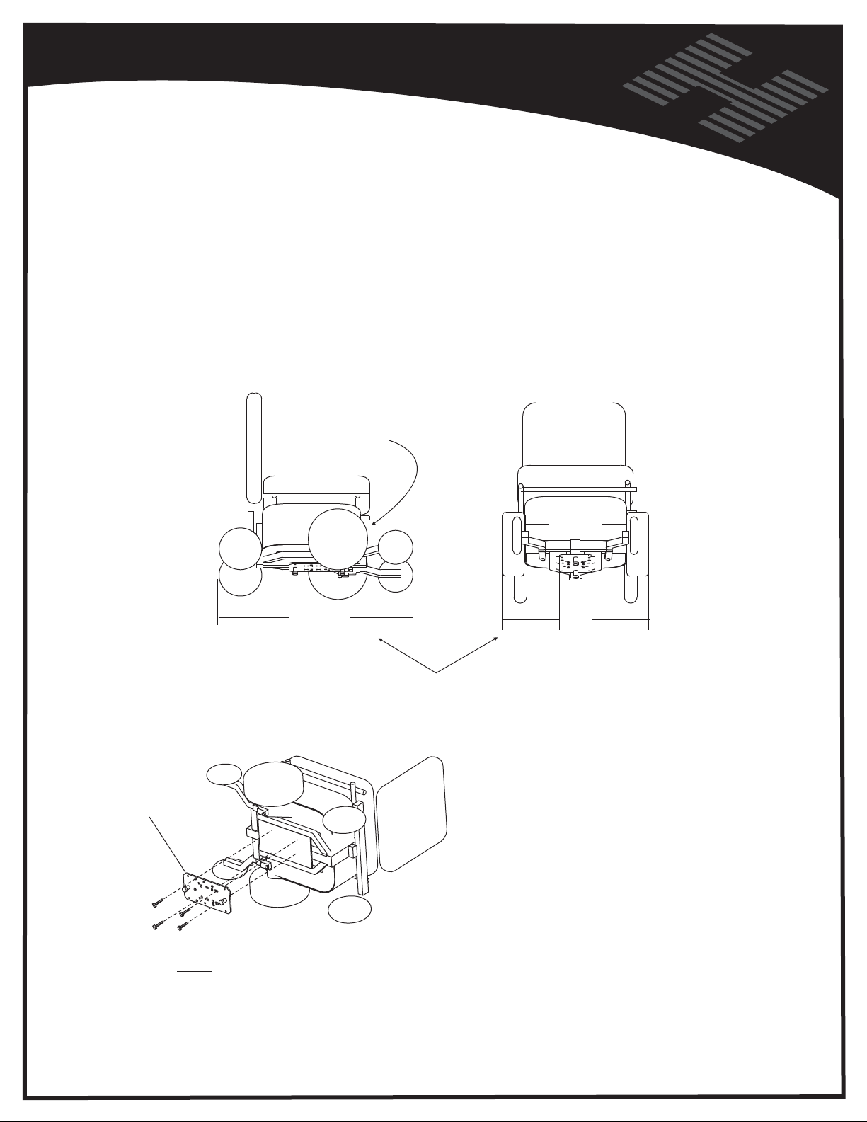
INSTALLATION
CHAIR PREPARATION
AL550 only
CHOOSING A LOCATION and MOUNTING THE DOCKING DEVICE PLATE
WARNING: Do not attempt to use this automatic lock down device
on any folding, or take apart chairs unless recommended
by Harmar.
The closer the plate is
positioned to the drive
wheels, the easier the
chair will be to engage
the Locking Device
DOCKING
DEVICE
PLATE
Drive
wheel
Find approximate
center of the chair
Use existing holes where ever possible.
If too little or no holes exist,
holes need to be drilled. Remove
power chair's batteries, and use
plate as a template.
Drill as required.
Attach to chair using supplied
hardware.
DO NOT USE SPACERS HERE
SPACERS BELONG UNDER THE
STATION ON THE PLATFORM
4---1/4-20 x 1.00" HHCS
4---1/4-20 Nylock Nut
ATTACHED TO PLATE
9
Page 10
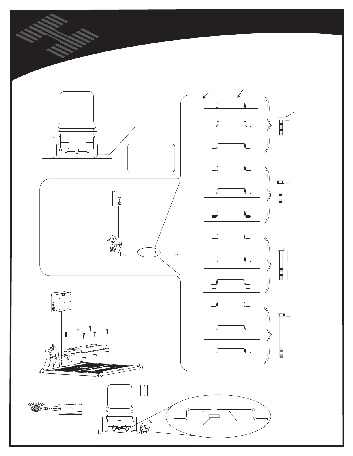
Vehicle Hitch
AL600 & AL690
CHAIR PREPARATION
AL550 only
SETTING DOCKING DEVICE HEIGHT
Determine
number
of spacers
required for
your ground
clearance
Measure distance of
mounting surface
to ground
PRIOR TO MOUNTING
DOCKING PLATE TO CHAIR
Ground clearance
MUST be greater
than or equal to
1.75"
If ground
clearance =
1.75" - 2"
2.25"
2.5"
2.75"
3"
3.25"
3.5"
Then use:
No Spacers
.25" spacers
0.25" 0.25"
.5" spacers
.75" spacers
0.25"
0.50"
1" spacers
1.00" 1.00"
1" + .25" spacers
0.25" 0.25"
1.00" 1.00"
1" + .5" spacers
0.50" 0.50"
1.00" 1.00"
Hardware Used:
( from hardware pack )
Mounted on lift
from factory
1"
x6
0.50"0.50"
0.25"
0.50"
1.75"
x6
Drive Chair onto Lift
look down the entry
point of the
locking device
Remove Locking
Device and insert
appropriate number
of spacers.
Re-attach to platform.
( change to longer
screws if )
necessary
1"+ .5" + .25" spacers
0.25" 0.25"
3.75"
0.50" 0.50"
1.00" 1.00"
1"+ 1" spacers
4"
1.00" 1.00"
1.00" 1.00"
1"+ 1" + .25" spacers
0.25" 0.25"
4.25"
1.00" 1.00"
1.00" 1.00"
1"+ 1" + .5" spacers
0.50" 0.50"
4.5"
1.00" 1.00"
1.00" 1.00"
1"+ 1" + .5" + .25" spacers
0.25" 0.25"
0.50" 0.50"
4.75"
Verify the head of the shoulder bolt is
below the underside of the locking device.
UP TO A 1/4" OF SPACE IS ACCEPTABLE
1.00" 1.00"
1.00" 1.00"
1
4"
Shoulder
Bolt Head
Underside
of Locking
Device
2.5"
x6
3.25"
x6
Perform lock down test
on next page to assure
installation of Docking
Device Plate and Locking
Device are correct.
10
Page 11
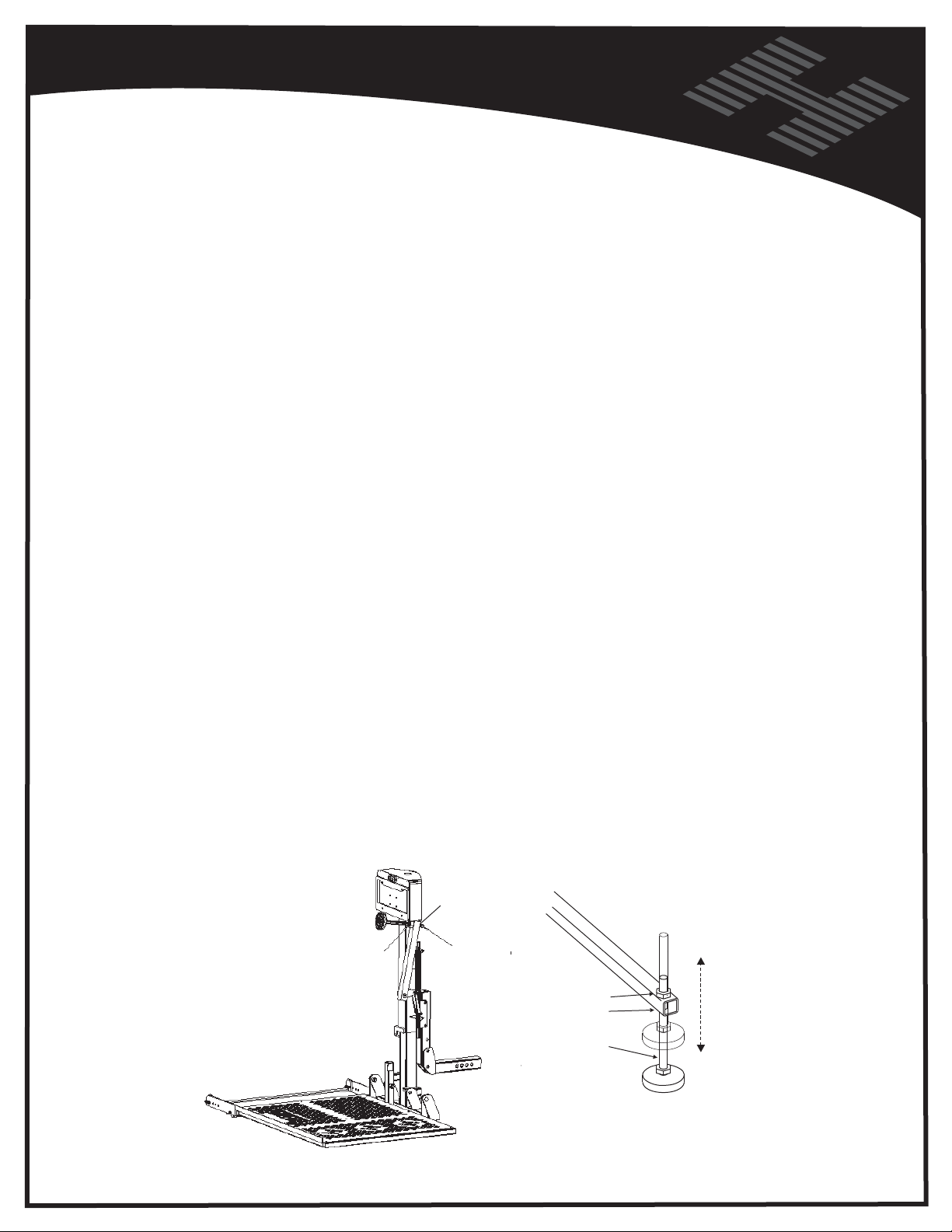
LIFT PREPARATION
AL100
SETTING HOLD DOWN FOOT HEIGHT
With platform on the ground, drive scooter onto platform, from left (driver's side ) to right, until the rear
wheels are located in the rear wheel spreader bar assembly. Stop when the rear tires contact the ramp
on the platform.
Raise the platform on either lift until the motor's clutch
is heard ( top of travel ). Loosen both nuts on hold down arm, and thread the Hold Down Foot down to
the scooter's deck. Lower Platform about 1-2 inches. Thread Hold Down Foot down once again to
scooter's deck. Raise Platform. Verify Hold Down Foot places adequate pressure on scooter.
DO NOT
adjust the leg so far down that the top of the threaded rod does not protrude through the top
of the pivot tube. Once the foot is adjusted to the proper position, tighten the jam nut to lock it in place.
Once the lift is properly adjusted, lower the platform to the ground and raise it back to the
transporting position. Repeat this several times to make sure all parts are operating properly and
that the scooter is properly secured. Next, remove the scooter from the lift and using the toggle
switch, cycle the lift completely up and down to make sure that all parts are in working order and the
lift fol ds up when it is empty.
Caution: On some scooters, it may be necessa ry to temporarily move the steering tiller forward to
clear the hold down arm as it lowers into the lock down position.
Caution: Some scooters have pneumatic (air inflated) tires. If your scooter has this type tire, be
sure the tires are properly inflated. Improper inflation of the tires will change the deck height of the
scooter and therefore change the amount of clamping force the hold down arm places on the
scooter. The scooter can fall off of the lift if not properly secured.
Caution: Be sure to instruct the end user not to enter steep driveways straight on. Enter and leave
at an angle to the street so that your lift platform does not drag on the ground.
NOTE: Drive the scooter off in REVERSE. When the scooter is clear of the platform, raise t
he
platform by pushing up on the UP/DOWN switch.
NUT
NUT
END OF THREADED ROD
MUST PROTRUDE
THROUGH TOP OF
TUBE AND NUT
Turn threaded rod
11
Loosen top nut
and bottom nut
to lengthen or
shorten foot
Page 12
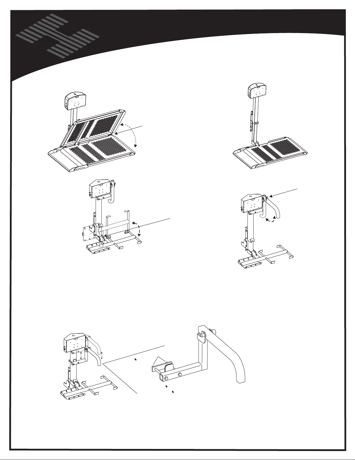
Vehicle Hitch
LIFT PREPARATION
AL010/050 and AL030 PIVOT POINT ADJUSTMENTS
N
O
I
S
N
E
T
T
S
U
J
D
A
The hinge points are equipped
with tensioning washers. The
amount of force required to move
these parts is determined by the
tension of these washers.
To adjust, simply loosen or tighten
the bolt and nut located by w/ arrows.
The tension is set at the factory and
should need no adjustment.
This is noted for reference only.
D
A
N
O
I
S
N
E
T
T
S
U
J
Al030 HOLD DOWN ARM ADJUSTMENT
ADJUST TENSION
Loosen nuts here
Slide arm up or down tube
LIFT SHOULD HOLD
WHEELCHAIR FIRMLY
WITH THE PLATFORM
FULLY RAISED
( RAISED UNTIL
MOTOR RATCHETING
IS HEARD )
Tighten after adjustment
12
Page 13
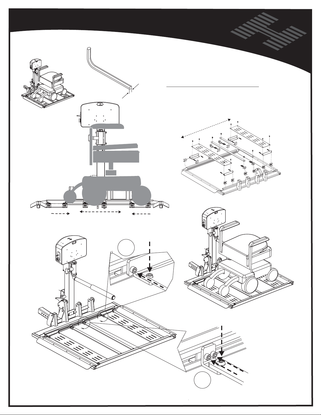
LIFT PREPARATION
AL 560
ALLEN WRENCH REQUIRED
3/16 “
FOR ADJUSTMENT PURPOSES,
ALL PLATFORM COMPONENTS ARE
SHIPPED LOOSE
AND MUST BE FIRMLY TIGHTENED
ADJUST
BARS and
PLATFORM
SKINS TO
CAPTURE
CHAIRS
WHEELS.
SLIDE TO CAPTURE CHAIR’S WHEELBASE
X8
IF NECESSARY, THE
COMPONENTS MAY BE
RE-ARRAN
FRONT or REAR
DRIVE WHEELS
GED FOR
USE FOR DRIVE WHEELS
US
E FOR DRIVE WHEELS
ONCE ADJUSTED
BE SURE TO TIGHTEN ALL FASTENERS
13
X4
Page 14
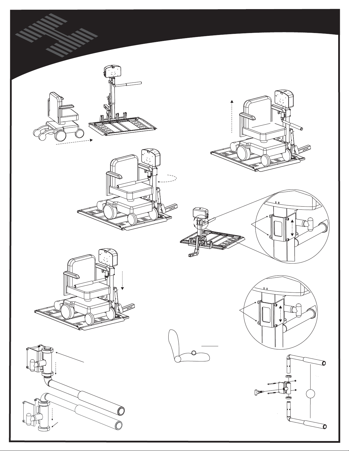
PULL RED “T” HANDLE
ROTATE ARM TO OVER SEAT
LIFT PREPARATION
AL 560
HOLD DOWN ARM HEIGHT ADJUSTMENT
DRIVE CHAIR ON PLATFORM
RAISE PLATFORM
UNTIL CLUTCH
DROP ARM
TO CONTACT SEAT
LOWER LIFT
APPROXIMATELY
2-3 INCHES
HIGHER ARM SETTINGS
CAN BE ACHIEVED BY
REMOVING TOP
SHAFT COLLAR,
RETRACTING
T HANDLE AND
RE-INSERTING ARM
FROM ABOVE.
LOOSEN BOLTS
DROP ARM AGAIN
TO CONTACT SEAT
TIGHTEN BOLTS
VERIFY ARM PRODUCES
ENOUGH PRESSURE ON
SEAT TO FIRMLY HOLD
POWER CHAIR TO PLATFORM
SEAT SHOULD BE SOMEWHAT
DEFORMED BY ARM.
OR
REPLACE
SHAFT
COLLAR
THIS METHOD ALLOWS THE RED “T” HANDLE
TO REMAIN ON THE SAME SIDE AS THE KEY
AND TOGGLE SWITCHES.
14
Page 15
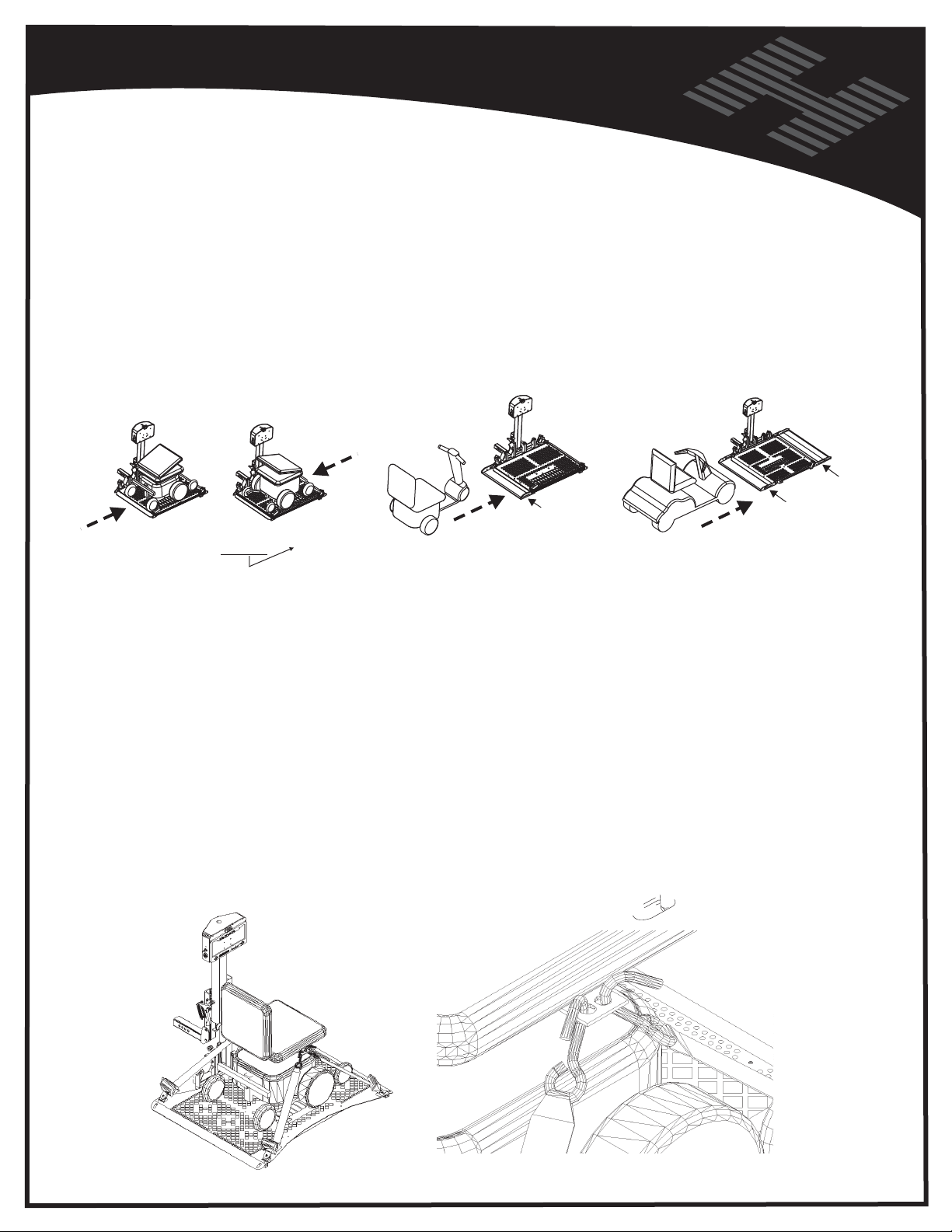
OPERATION
General Operating Instructions:
Turn the key switch to the ON position. With the toggle switch, raise and lower the platform as
needed. Pushing the switch downward will cause the platform to lower. The platform will first unfold
to the horizontal position, then continue lowering to the ground. Release the UP/DOWN toggle
switch just as the platform reaches the ground. Do not attempt to raise the rear of the vehicle with
the lift or damage could be done to your lift or vehicle.
Drive the chair/scooter onto the platform as close to the center of the platform as possible. Follow
the instructions for securing the chair/scooter onto the lift. Raise the platform to the transporting
position. Now lower the platform to the ground. Repeat this action to make sure all parts are
operating properly and the chair is properly secured.
OR
REAR
Depending on
AL500, AL550 AL100, AL300 AL301XL
Docking Station
Arrangement
WHEELS
REAR
WHEELS
FRONT
WHEELS
Next, remove the chair/scooter from the lift and using the toggle switch, cycle the lift completely up to
make sure that all parts are in working order and that the lift folds up when it is empty.
Make absolutely sure the chair/scooter is properly secured by the locking mechanisms. Be sure
everything is in proper working order before transporting any chair/scooter.
CAUTION: Keep hands and feet out from under the platform as it
raises and lowers.
CAUTION: Before driving off with the chair/scooter on the lift, make sure that the chair/scooter is
firmly held down on the platform.
CAUTION: When driving with the chair on the lift, instruct the end user to slow down for pot holes,
speed bumps, railroad tracks, etc. The lift could be damaged by this type or similar abuse. Lifts are
subjected to exc essive loads imposed by rough driving.
CAUTION: Be sure to instruct the end user, do not enter steep driveways straight on. Enter and
leave at an angle to the street so that the lift platform does not drag on the ground.
15
Page 16
Vehicle Hitch
To unload the power chair, simply turn ON the power switch and push the UP/DOWN toggle switch
to the down position. Hold the s witch down until the platform just touches and is level to the ground.
Press the red release button on the Anchor Strap Base to release the tension and unhook the strap
from the chair. Continuing to press the button, allow the strap to retract until the hook reaches the
housing. Repeat this step on each corner until all four straps are released. Drive your power chair
off the lift platform. When the power chair is clear of the platform, raise the platform by pushing up
on the UP/DOWN switch.
To bring the lift in the empty, stowed position, hold the UP switch. The platform will start up in the
horizontal position. During its travel upward, the platform will fold up into the stowed or vertical
position. Hold the switch until the platform travel stops automatically.
Courtesy Note: You may wish to advise the end user to remove the key from the power switch to
avoid any tampering with the lift.
OPERATION
Special Note:
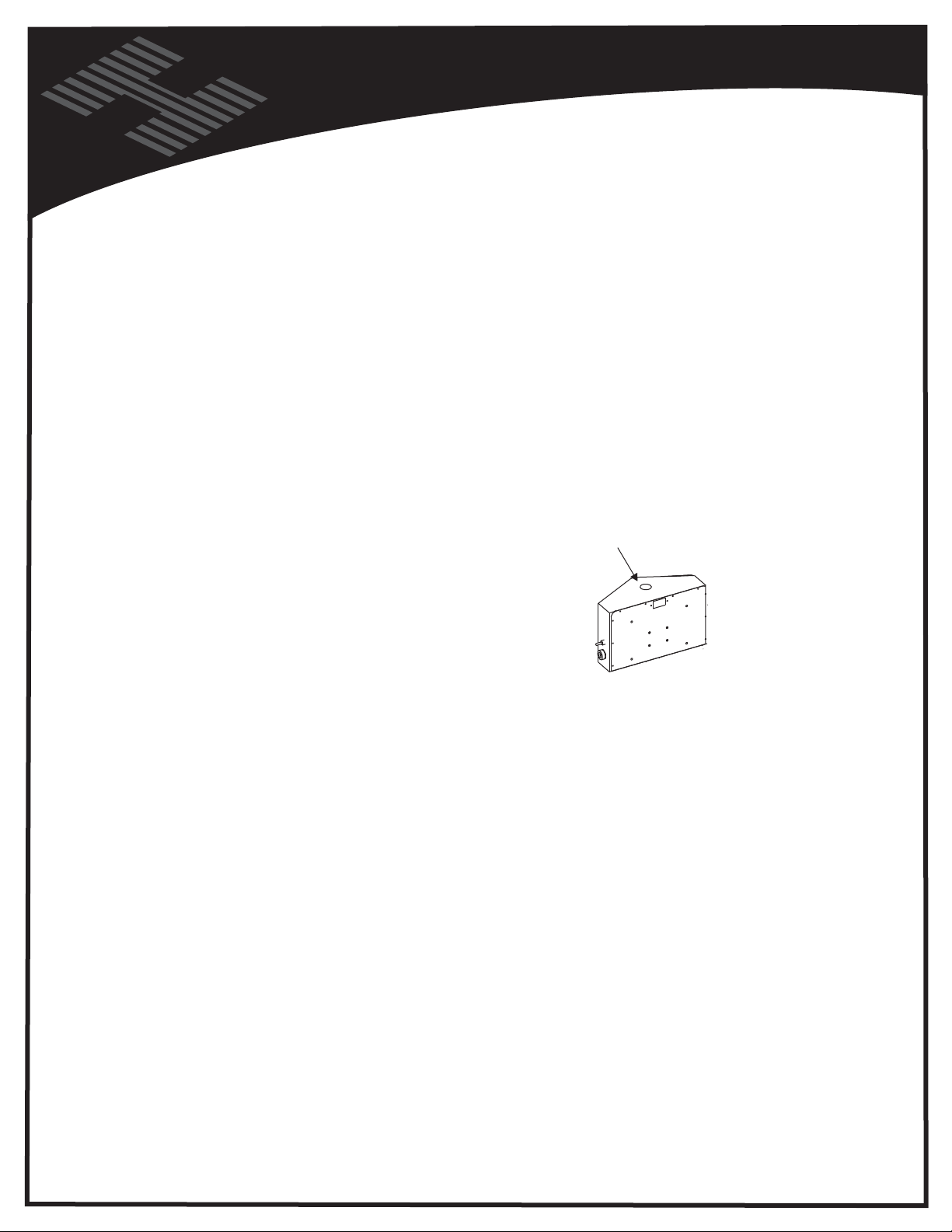
The lift features 1 of 2 Manual overrides ( both in the same location )
If the vehicle or lift loses power, simply remove the caution sticker
from the top of the motor box. TURN KEY OFF, and REMOVE 2 PRONG
WIRING FROM THE LIFT TO AVIOD INJURY SHOULD
POWER SUDDENLY BE RESTORED. Some lifts require a 3/8"
socket, others require a 1/2" socket. Turn the wrench clockwise to
raise the lift and couter clockwise to lower.
Do not attempt to move the vehicle without the lift in the stowed or travel position. Any attempt to
move the vehicle without the lift fully up may cause damage to the lift, power chair, scooter or
vehicle.
The AL100 is shipped with the Spreader Bar Assembly already attached to the back of the platform
on the lift. You must rotate it down until the hole in the side bracket lines up with the open hole on
the attachment point on the platform. The Spreader Bar should be flat on the ground at this point.
Tighten the bolts where the Spreader Bar Assembly attaches to the platform.
Load the scooter on the center of the platform. Adjust the spreader bar according to the size of the
scooter that is being transported on the lift. Forward for smaller scooters and back for larger
scooters. Make sure that all fasteners on the Spreader Bar Assembly are t ightened before
attempting to use the lift.
With the toggle switch, raise the platform with the scooter on it. You will notice that as the lift
reached the top, the hold down arm with the foot will lower to the deck of the scooter. The foot
should put pressure down on the deck of the scooter to secure it in place while traveling. If the foot
does not reach the scooter, unthread the adjustable leg until the foot rests securely on the deck of
the scooter.
(If the lift does not
operate properly,
immediately take
it to the local dealer.
DO NOT attempt to
modify the lift in
any way!)
Thread the Adjustable Hold Down Foot onto the hold down arm. To begin, thread the rod completely
into the arm. Lower the platform to the ground and place the scooter to be used on the lift and using
the toggle switch, raise the platform and scooter up until it reaches the traveling position (all the way
up). The lifting motor has a clutch mechanism that will stop the lift when it reaches the top. You will
hear a clicking sound when the lift is at the top. Release the switch at this time.
16
Page 17
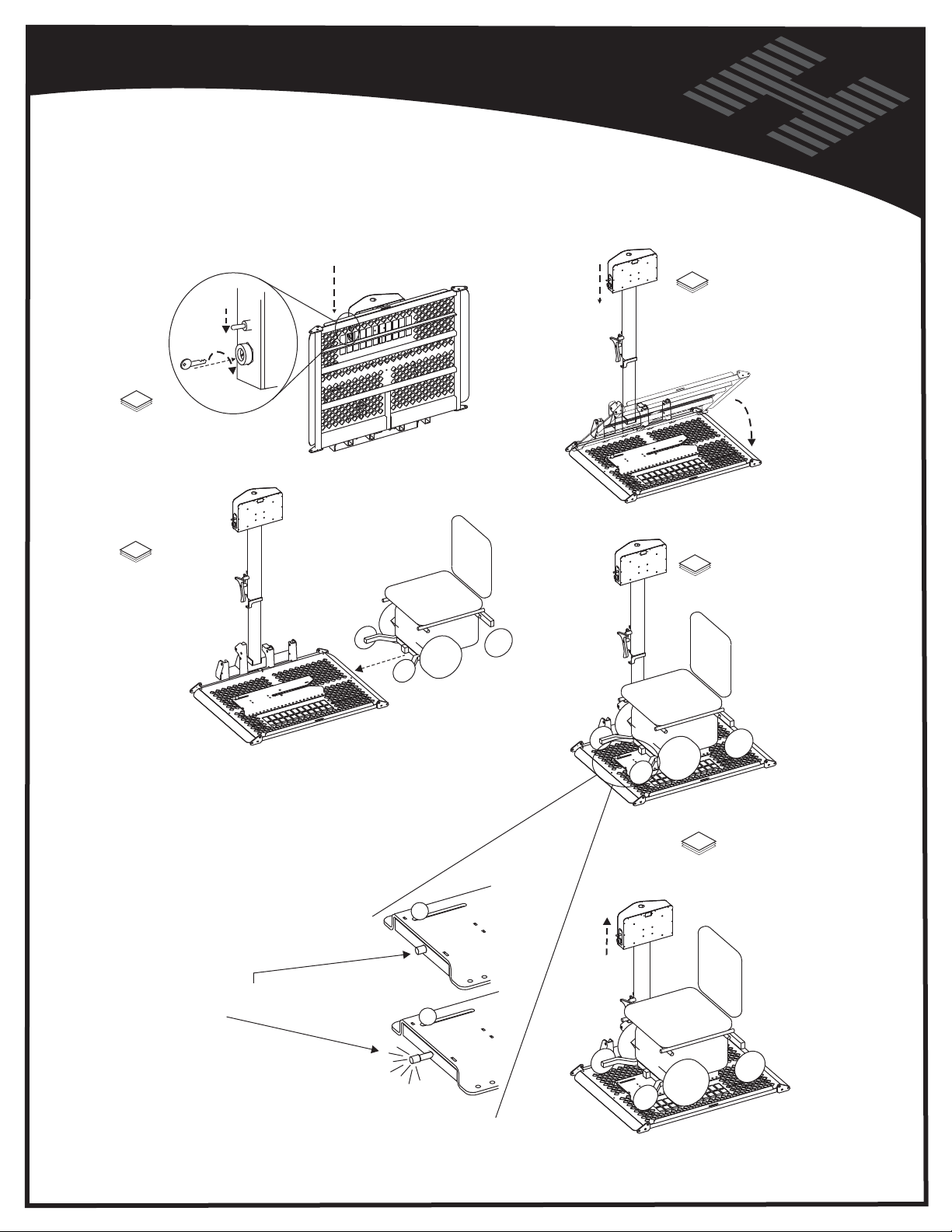
OPERATION
AL550
LOADING THE POWER CHAIR
UP
DOWN
ON
1
Insert and turn key.
Press down on switch
to lower platform.
2
Continue to lower as
platform automatically
unfolds. Stop when
platform reaches ground.
3
Slowly drive chair
unto platform as
shown.
THREE WAYS TO VERIFY YOUR CHAIR
IS SUCCESSFULLY LOCKED DOWN
1) AUDIBLE "CLICK or POP" SOUND
As the chair enters the locking device,
it should be driven forward until an audible
pop or clicking sound is heard. This sound
is the locking device setting itself around
the chair's docking device pin.
2) VISUAL INDICATOR
The yellow indicator will extend and stay
extended when the chair is successfully
locked in place.
4
TEST LOCKING DEVICE
SLOW
5
AFTER ALL THREE
TESTS ARE PERFORMED
Raise platform until motor's
clicking noise is heard
NOT
LOCKED
3) REVERSE TEST
Attempt to back the chair off the platform.
The chair will NOT move in any direction
when successfully locked.
LOCKED
Your chair is now ready
for transport. Remove key
if desired.
17
Page 18
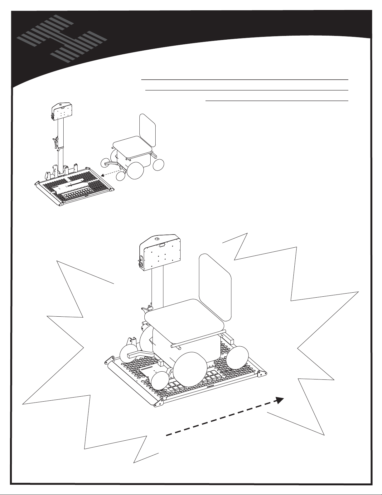
Vehicle Hitch
SLOW
OPERATOR RESPONSIBILITY - AL 550
VERIFY THE CHAIR HAS BEEN LOCKED INTO
THE DOCKING STATION BY ATTEMPTING TO
DRIVE CHAIR OFF IN REVERSE
THE DOCKING STATION WILL
“CLICK” or “POP” AND The YELLOW
INDICATOR WILL EXTEND
BUT THE MOST EFFECTIVE WAY
TO ASSURE THE SAFETY OF YOUR \
POWER CHAIR IS TO PERFORM
THE REVERSE TEST EACH TIME
YOUR POWER CHAIR IS LOADED
TEST
18
Page 19
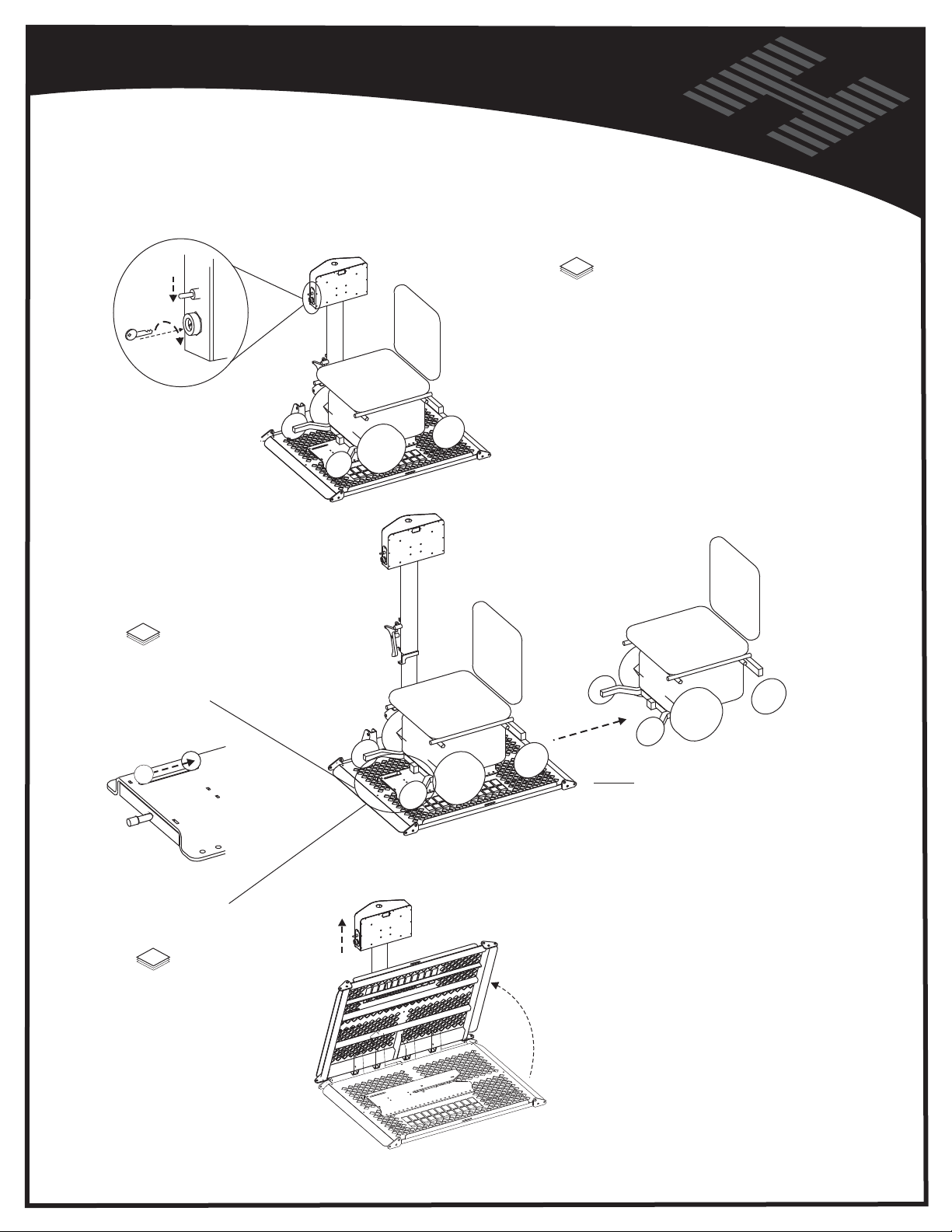
OPERATION
AL550
UNLOADING THE POWER CHAIR
UP
DOWN
ON
2
TO RELEASE CHAIR
Slide knob this direction
1
Insert and turn key.
Press down on switch
to lower platform.
To avoid bending over,
you may wish to release
chair from Locking Device
prior to lowering platform.
Be sure the drive wheels
are engaged, and the chair's
power is OFF.
Slowly back chair
off platform
3
Raise the platform
by pressing up on
the switch until
motor's clicking
noise is heard.
Platform will fold
automatically.
Remove the key
if desired.
NOTE: During transport, vibration
may cause the chair to tighten itself in
the locking device, making the release
knob difficult to slide. To overcome this,
simply drive the chair forward a bit.
This will take pressure off the knob,
allowing an easier release.
Once the chair has left the locking device,
it automatically resets itself to accept the
next time the chair needs to be transported.
No adjustment of the release knob is required.
19
Page 20
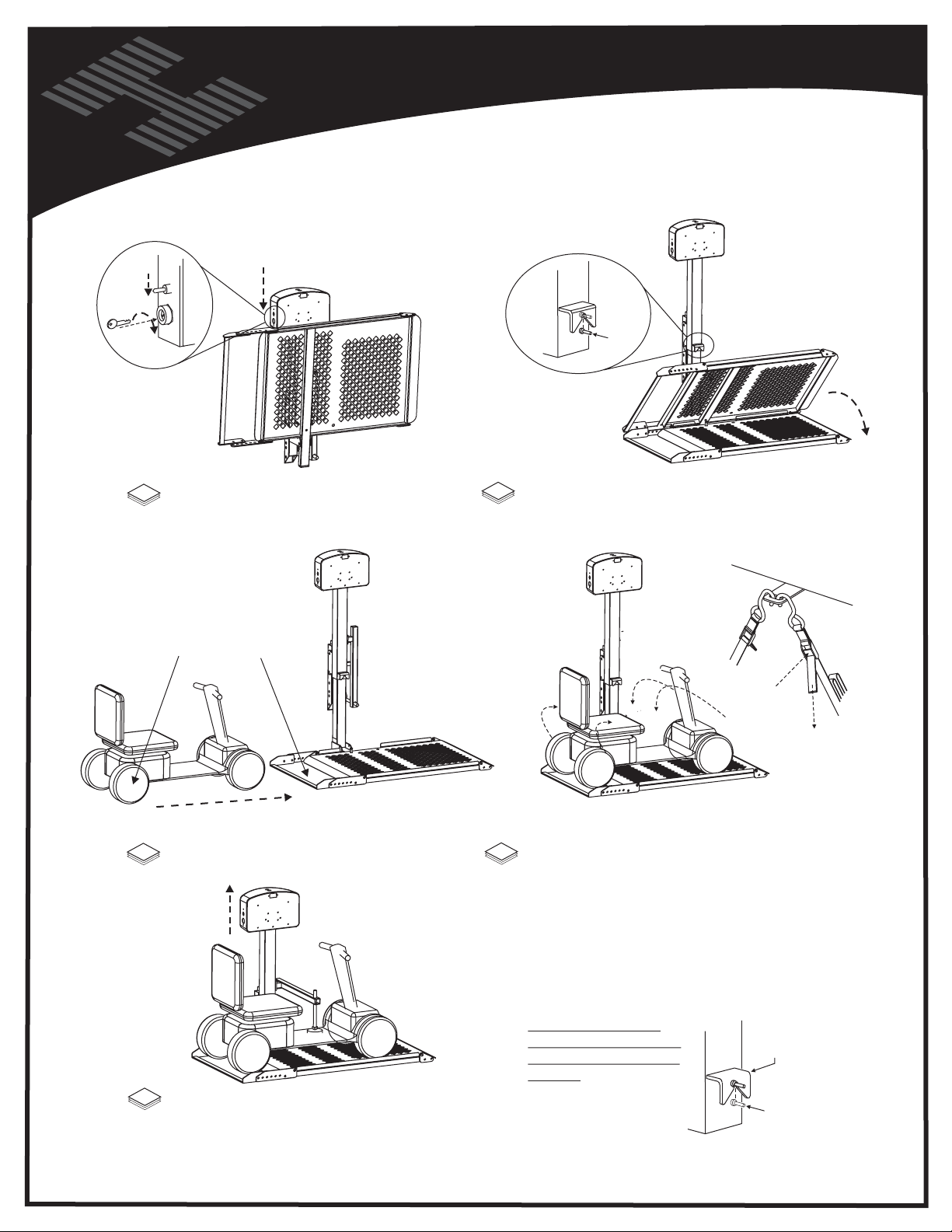
Vehicle Hitch
UP
DOWN
OPERATION
AL 010 / 050
LOADING A SCOOTER
"PLATFORM KEEPER"
ON
1
Insert Key and switch to "ON" position
Press down on Toggle switch momentarily.
Rear Wheels in Craddle
WELDED TO
PLATFORM
2
Once platform has been lowered at least an
inch, unfold the platform. Continue lowering
to the ground.
PUSH to
RELEASE
PULL to
TIGHTEN
3
Drive scooter onto platform as shown.
5
Raise platform until hold down foot depresses
scooter's deck or until lift's motor ratchets.
20
4
Strap the scooter down using the 4 straps
located on each corner of the platform.
To remove the scooter and prepare the lift
for unloaded travel, follow above steps in
reverse order and reverse the direction
of the arrows.
Lift should be raised
with the platform folded
and until the lift's motor
ratchets. Verify that the
platform keeper has
engaged the platform's
pin.
ATF
PL
ORM KEE
PL
ATFORM's PIN
PER
Page 21
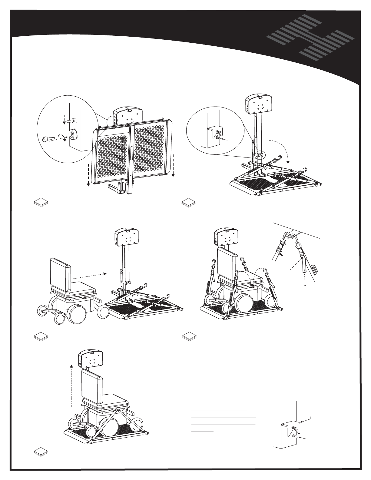
OPERATION
AL 010 / 050
LOADING A POWER CHAIR
"PLATFORM KEEPER"
UP
DOWN
ON
1
Insert Key and switch to "ON" position
Press down on Toggle switch momentarily.
WELDE
D TO
PLATFORM
NOTE: The Platform will not be
allowed to unfold until the platform
has been lowered at least an inch.
2
Once platform has been lowered at least an
inch, unfold the platform. Continue lowering
to the ground.
PUSH to
RELEASE
PULL to
TIGHTEN
3
Drive chair onto platform as shown.
5
Raise platform with toggle switch, until
motor's ratchet sound is heard.
4
Strap the chair down using the 4 straps
located on each corner of the platform.
To remove the chair and prepare the lift
for unloaded travel, follow above steps in
reverse order and reverse the direction
of the arrows.
Lift should be raised
with the platform folded
and until the lift's motor
ratchets. Verify that the
platform keeper has
engaged the platform's
pin.
21
PLATFORM KEEPER
PLATF
ORM's PIN
Page 22
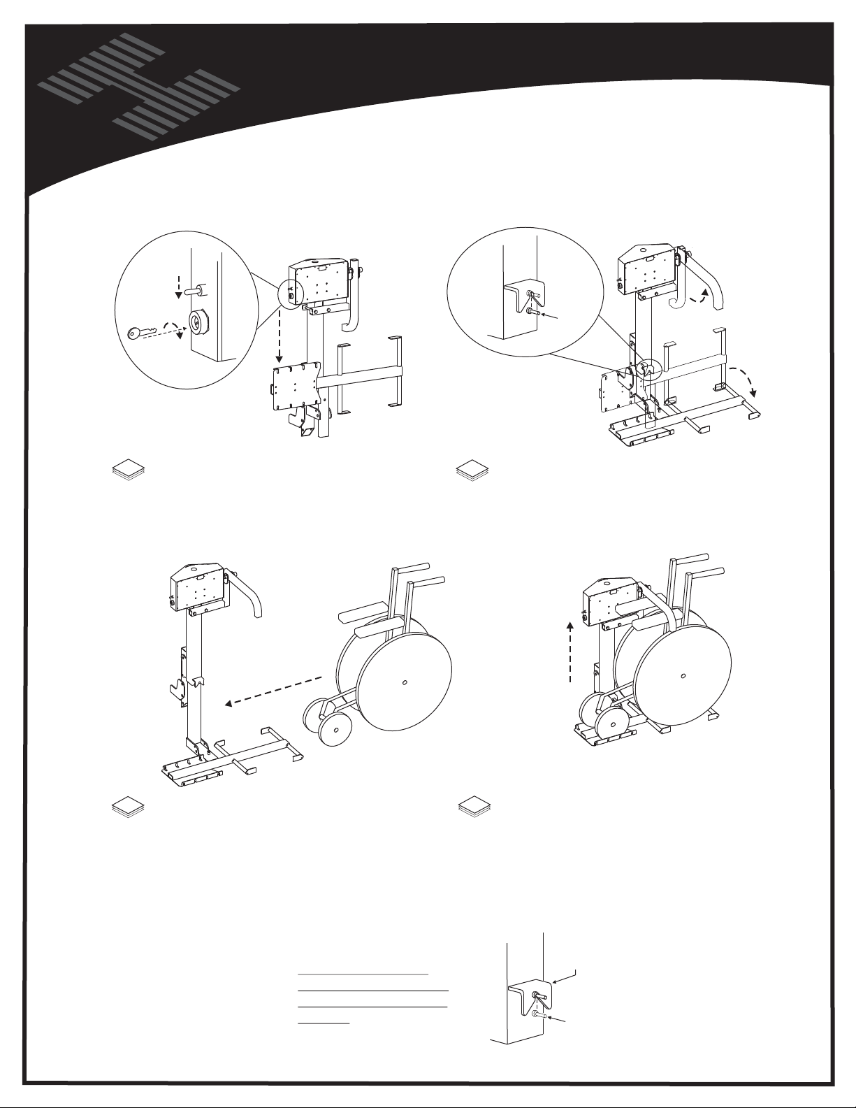
Vehicle Hitch
UP
DOWN
ON
LOADING THE WHEELCHAIR
"PLATFORM KEEPER"
WE
LDED
PLATFORM
NOTE: The Platform will not be
allowed to unfold until the platform
has been lowered at least an inch.
OPERATION
AL030
TO
1
Insert Key and switch to "ON" position
Press down on Toggle switch momentarily.
3
Roll folded chair onto platform as shown.
2
Once platform has been lowered at least an
inch, unfold the platform. Continue lowering
to the ground. Raise hold down arm.
4
Raise the lift until hold down arm has
contacted wheelchair's arm rests.
To remove the chair and prepare the lift
for unloaded travel, follow above steps in
reverse order and reverse the direction
of the arrows.
Lift should be raised
PLATFO
with the platform folded
and until the lift's motor
ratchets. Verify that the
platform keeper has
engaged the platform's
pin.
22
RM KEEPER
PLATFORM
's PI
N
Page 23
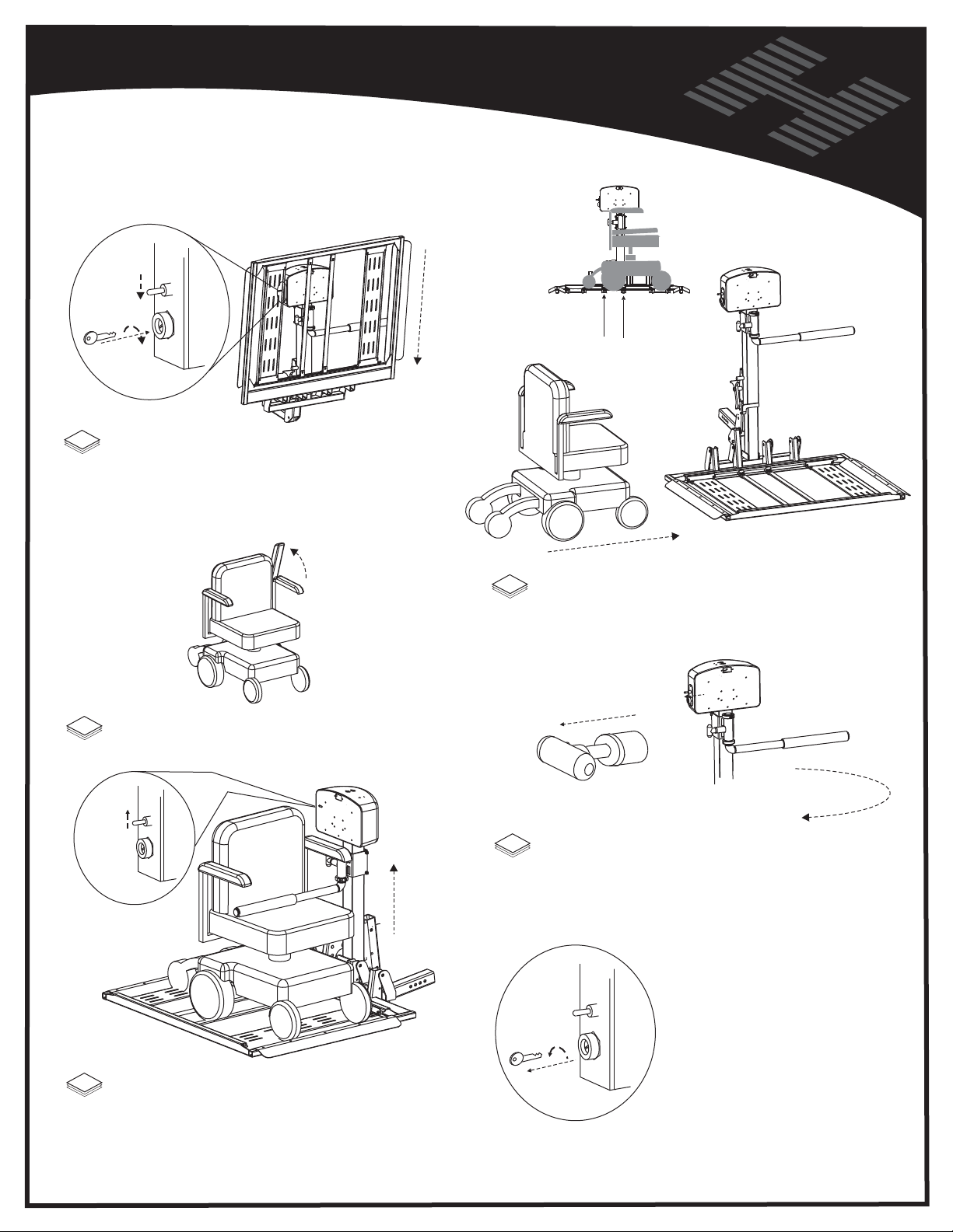
OPERATION
AL 560
LOADING A POWER CHAIR
UP
DOWN
ON
1
Insert Key and switch to "ON" position
Press down on Toggle switch and the
platform will unfold. Continue to lower
until platform reaches the ground and
becomes level.
3
Rotate the Chair’s Inner Arm Rest upwards
and out of the way of Hold Down Arm.
UP
DOWN
ON
2
Drive the Chair onto the platform taking care
to stop when the drive wheels fall between the
bars in the platform.
4
Pull the RED “T” Handle
while rotating the Hold Down Arm. Release
“T” Handle to allow arm to lock in position.
Turn “OFF” and remove
Key if desired
UP
DOWN
Your Power Chair is now
ready for transport.
Press “UP” on toggle to raise Platform until ratchet
5
sound is heard. Hold Down Arm will squish seat,
and lock Power Chair in place. If desired, rotate
arm rest back to original location.
23
ON
To remove the chair and prepare
the lift for unloaded travel, follow
above steps in reverse, and reverse
direction of the arrows.
Page 24
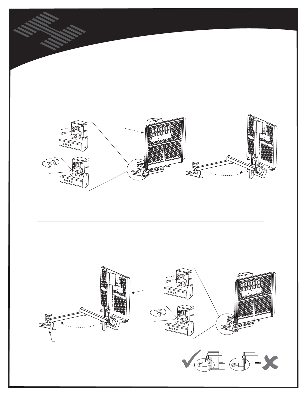
Vehicle Hitch
Many scooter and chair owners require access to the rear of a vehicle. To accomplish this a Swing Away option is
added to the lift installation. This allows the complete lift to be conveniently and easily swung away from the back of the
vehicle and allow easy access to the trunk or lift gate. The Swing Away option can be purchased from any authorized
dealer and added at any time.
OPENING THE SWING AWAY:
REMOVE
SAFETY
PIN
OPERATION
Operating the Swing Away
PUSHING
AWAY
LIFT
PULL RED
HANDLE
WHILE...
Grasp the lift firmly and swing it out away from the vehicle.
The Swing Away can be opened up to 180 degrees from the
closed position to allow full access to the rear of the vehicle.
IMPORTANT
This will cause damage to the Swing Away, lift and potentially cause damage to the vehicle and the chair!!
CAUTION!!
Failure to do so may result in the operator losing control of the lift causing damage to persons and property.
CLOSING THE SWING AWAY:
"SLAM-SHUT" DESIGN
CLOSE SWING AWAY
LIKE A CAR DOOR
!! NEVER OPERATE THE SWING AWAY WITH THE CHAIR or SCOOTER ON THE LIFT!!
Always insure that the vehicle is on level ground before attempting to open the Swing Away.
INSTALL
SAFETY
PIN
KEEP CLEAR OF
LATCHING MECHANISM
CAUTION!! Always install the safety pin.
VERIFY RED
KNOB HAS FULLY
RETRACTED
SAFELY CLOSED
24
WRONG
Page 25

Safety & Maintenance
Caution: Keep hands away from PINCH POINTS.
As with most mechanical objects, the hinge point of a moving
part creates a pinch point. Be sure to not to stick fingers or extremities
at or near these points.
Inspect the condition of your lift often. If any parts are worn or damaged DO NOT USE THE LIFT.
Immediately contact the dealer you purchased the lift from for repairs.
Caution: Keep feet and any other objects out from under the platform as it lowers.
Caution: Some chairs and scooters have pneumatic (air inflated) tires. If your chair/scooter has this type tire, be sure
the tires are properly inflated. Improper inflation of the tires will change how the unit fits on the platform and therefore change
the amount of clamping force on the chair/scooter.
Caution: Before driving off with your chair or scooter on the lift, make sure that the chair/scooter is firmly held down
on the platform.
Caution: When driving with your chair or scooter on the lift, slow down for pot holes, speed bumps, railroad tracks, etc.
Your lift could be damaged by abuse if subjected to excessive loads imposed by rough driving.
Caution: Do not enter steep driveways straight on. Enter and leave at an angle to the street so that you lift platform does not
drag on the ground.
Caution: Do not attempt to move the vehicle with the lift platform in the down position. If moved this way, the lifting
mechanism will be damaged.
WARNING! This lift is not meant for human transport. Chair/Scooter must be unoccupied before operating lift.
These lifts are for chair and scooter transport only. Do not attempt to transport any other vehicles or materials on the lift
other than what it is designed for.
MAINTENANCE:
The Universal outside lift has been designed to be as trouble free as possible for the owner.
The maintenance schedule is no exception.
Every 30 days oil the pivot points on all moving parts.
During winter and under dirty and dusty conditions, re-grease the inside square tube every 30 days. Lower the platform
to the ground and clean the square shaft with mineral spirits, WD-40 or any good solvent. Once clean, grease the square
shaft with a high-grade water-resistant grease, such as boat trailer wheel bearing grease.
NOTE: Your lift was assembled at the factory with Slick 50 “ONE GREASE”.
Check for paint chips and touch up any bare metal with a good gloss black enamel or lacquer to inhibit rust.
This may be necessary more frequently when subjected to salt air or road salt.
Warranty:
This lift is covered by a three year factory warranty on materials and workmanship.
Contact your local dealer for more information.
25
Page 26

Troubleshooting Guide
The lift does not operate
The motor does not lift
the platform completely
when in use.
The motor works
intermittently
Check the power supply. The wiring harness ( both wires ) must be
run directly to the battery. Attaching the black ( ground ) wire to the
frame of the vehicle is NOT considered a reliable ground.
Run the lift from a shop battery and not through the vehicle wiring
harness. If this solves the problem, check the vehicle wiring harness
for bad connections or broken wires. NOTE: Each lift is equipped with
a manual motor override located on the top of the motor box. Simply
remove the cap and use a 3/8” socket to manually operate the lift.
CAUTION!! Make sure the key is in the “off” position and no power
is connected to the lift. SERIOUS INJURY MAY OCCUR IF POWER
RESUMES DURING MANUAL OPERATION OF THE LIFT!
Check the wire connections at the battery. A poor connection will cause
the motor to run slow and have less lifting capacity. Run the lift from a
shop battery and not through the vehicle wiring harness. If this solves
the problem, inspect the entire length of the vehicle harness for breaks,
or worn insulation. A good supply of power will ensure full lifting capacity.
Check the ground and power wire making sure that it is securely
attached to the battery of the vehicle. Grounding the lift to any other
location may cause loss of ground and intermittent loss of power.
Check the wires leading to the toggle switch in the motor housing box.
All connections must be securely on the switch.
The platform or hold down
arm is not holding upright or
is too hard to move.
There is a ratcheting sound
when the lift is all the way up
or down.
The license plate light does
not work.
What do I do with the extra
length of wire leading to the
motor of the lift?
The lift does not reach the
ground when lowered completely.
The lift bottoms out when going
over bumps or in driveways.
Check the tension of the pivot point bolts. Two tight, and the
movement will be to too hard. Too loose and the part will not stay in the
desired position. Tighten or loosen bolts until platform and/or hold
down arm operates with some resistance.
This is a normal sound. It is the clutch activating when the lift reaches
the end position. This sound should only occur when the toggle switch
is being pressed and the platform is at its highest and lowest point.
This light runs from the 4 prong trailer plug located on the vehicle wiring
harness that powers the lift. Most hitch installers will install this type of
wiring when the hitch is installed. If no such plug exists, it may be wired
directly to a tail light or license plate light.
This wire is there in case a Swing Away Option is used with the lift.
If a Swing Away is not installed, coil the extra wire and zip tie it to the frame
of the lift out of the way of any moving parts. We recommend leaving the
wire in case a Swing Away is added to the lift at a later time.
Check the attachment of the Hitch Adapter to the Hitch Post on the back
of the lift. The normal range of operation for the lift is 5 to 18 inches to the
bottom of the hitch. Any higher vehicles will require a custom bracket.
Check the attachment of the Hitch Adapter to the Hitch Post on the
back of the lift . The normal range of operation for the lift is 5 to 18
inches to the bottom of the hitch. The lift should be installed at the
highest position possible. Enter driveways at an angle
I have lost my keys.
Contact the dealer where the lift was purchased. If they do no have
extra keys in stock, they can get them from the manufacturer.
26
Page 27
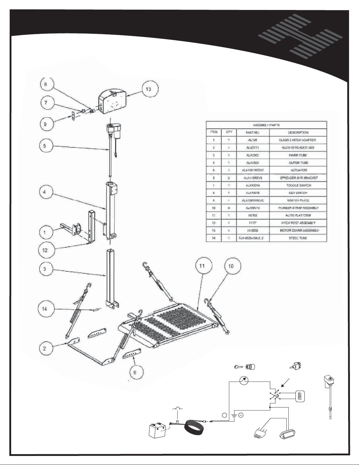
EXPLODED VIEW - AL-010/050
BATTERY
CIRCUIT
BREAKER
VEHICLE HARNESS
27
12V
+
KEYSWITCH
TRAILER PLUG
N
BROW
POLE REVERSING
SWITCH
MOTOR COVER
LIGHT
ACTUATOR
Page 28
Vehicle Hitch
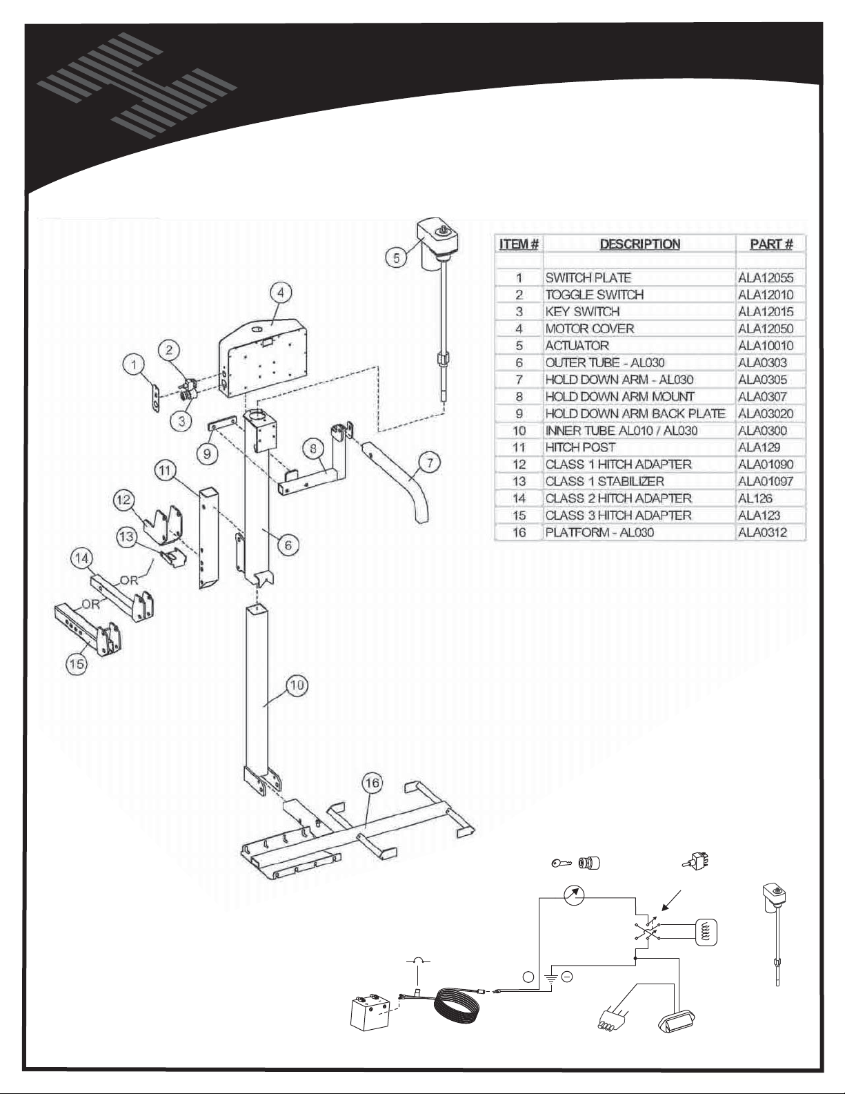
EXPLODED VIEW - AL-030
BATTERY
CIRCUIT
BREAKER
VEHICLE HARNESS
28
12V
+
KEYSWITCH
TRAILER PLUG
N
BROW
POLE REVERSING
SWITCH
MOTOR COVER
LIGHT
ACTUATOR
Page 29
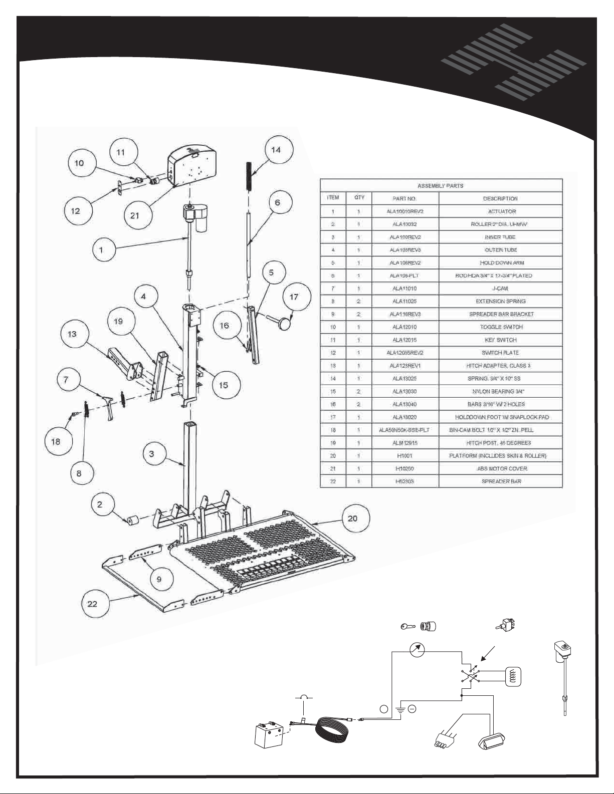
EXPLODED VIEW - AL-100
BATTERY
CIRCUIT
BREAKER
VEHICLE HARNESS
29
12V
+
KEYSWITCH
TRAILER PLUG
N
BROW
POLE REVERSING
SWITCH
MOTOR COVER
LIGHT
ACTUATOR
Page 30
Vehicle Hitch
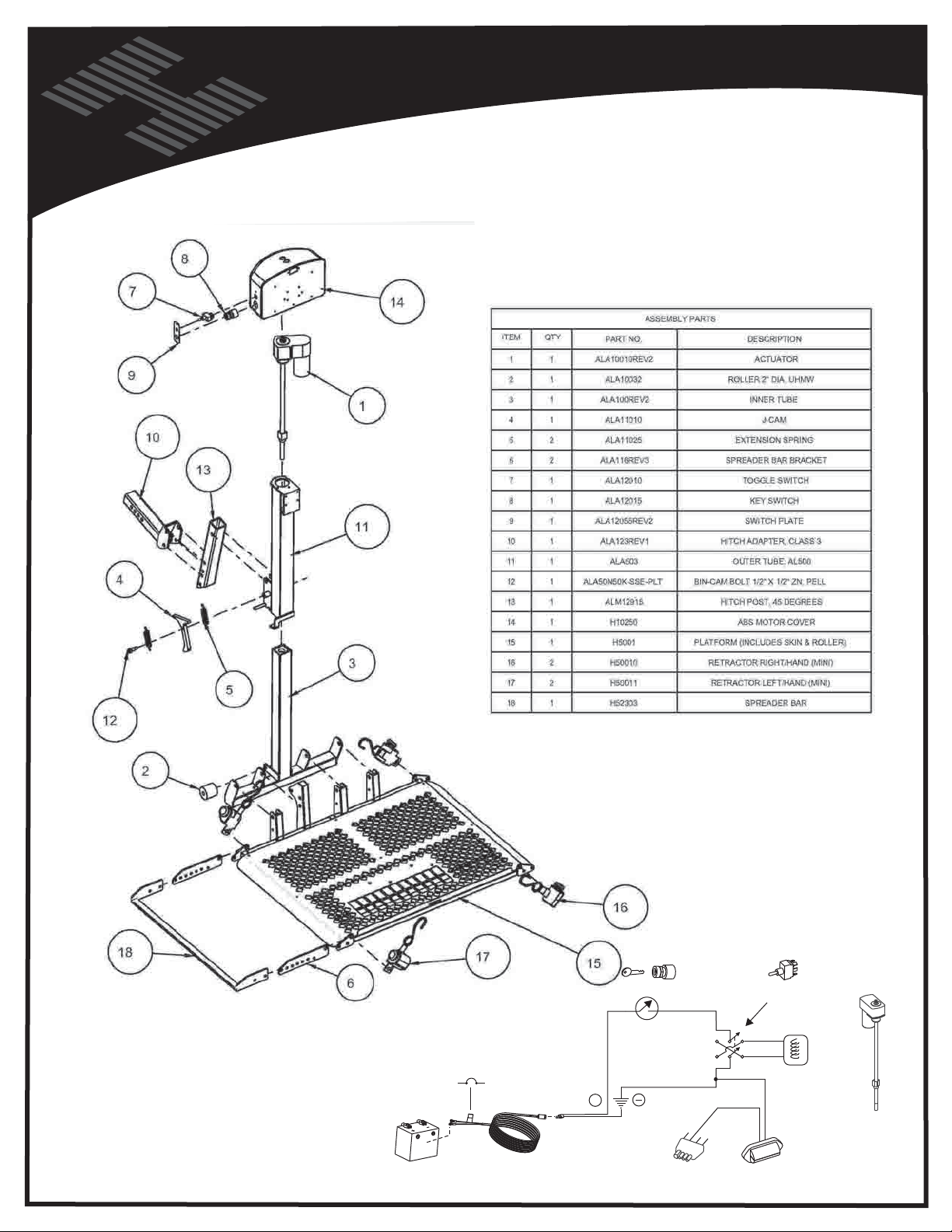
EXPLODED VIEW - AL-300
BATTERY
CIRCUIT
BREAKER
VEHICLE HARNESS
30
12V
+
KEYSWITCH
TRAILER PLUG
N
BROW
POLE REVERSING
SWITCH
MOTOR COVER
LIGHT
ACTUATOR
Page 31
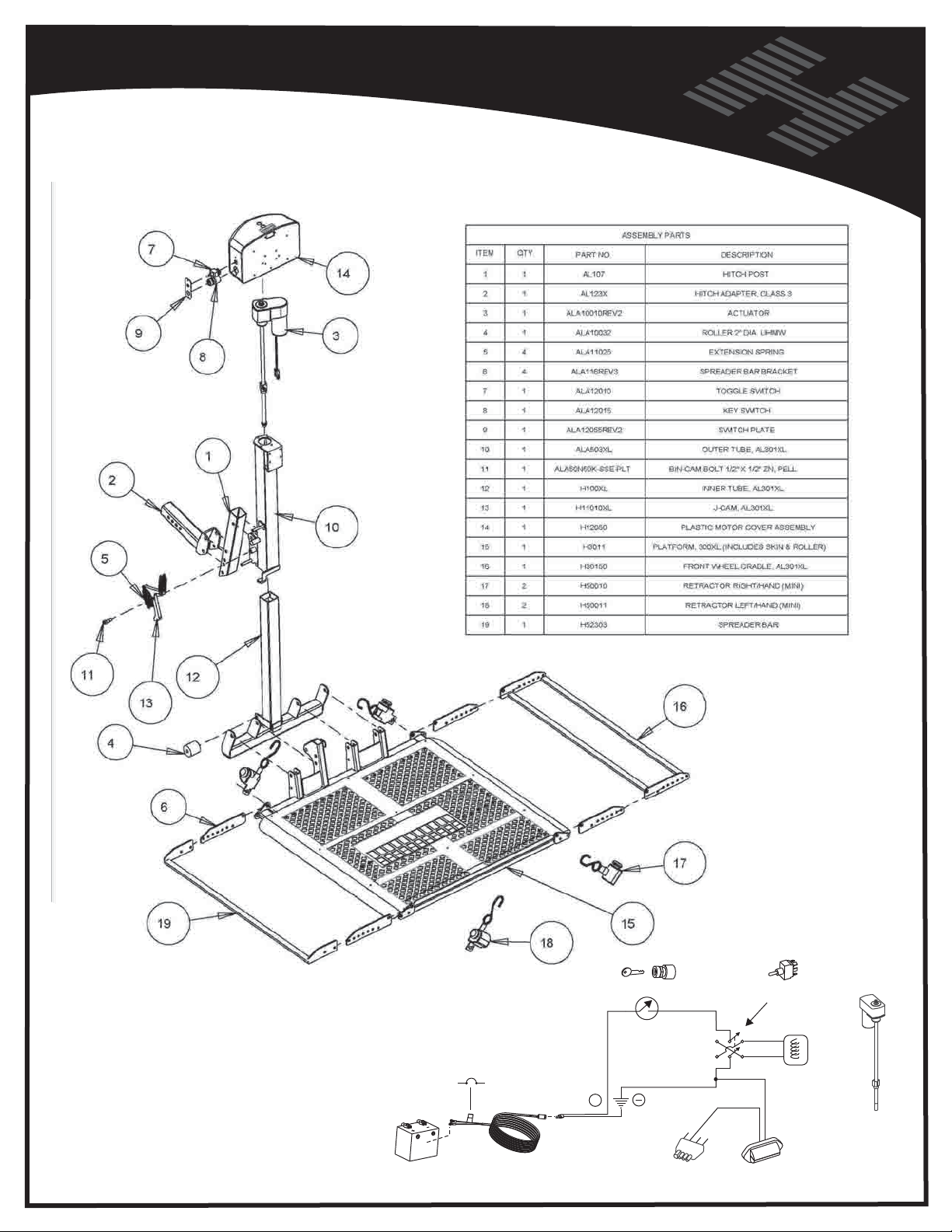
EXPLODED VIEW - AL-301XL
BATTERY
CIRCUIT
BREAKER
VEHICLE HARNESS
31
12V
+
KEYSWITCH
TRAILER PLUG
N
BROW
POLE REVERSING
SWITCH
MOTOR COVER
LIGHT
ACTUATOR
Page 32
Vehicle Hitch
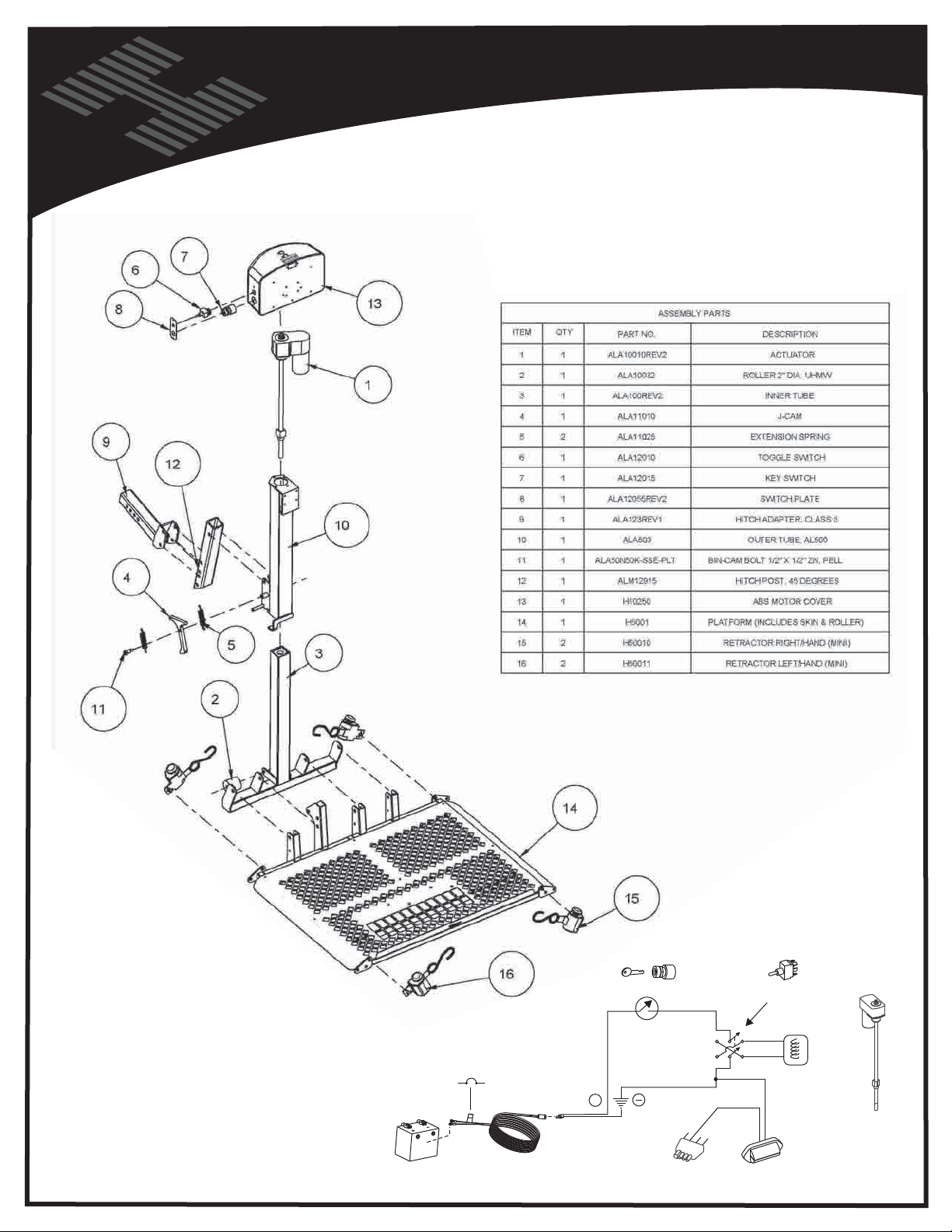
EXPLODED VIEW - AL-500
BATTERY
CIRCUIT
BREAKER
VEHICLE HARNESS
32
12V
+
KEYSWITCH
TRAILER PLUG
N
BROW
POLE REVERSING
SWITCH
MOTOR COVER
LIGHT
ACTUATOR
Page 33
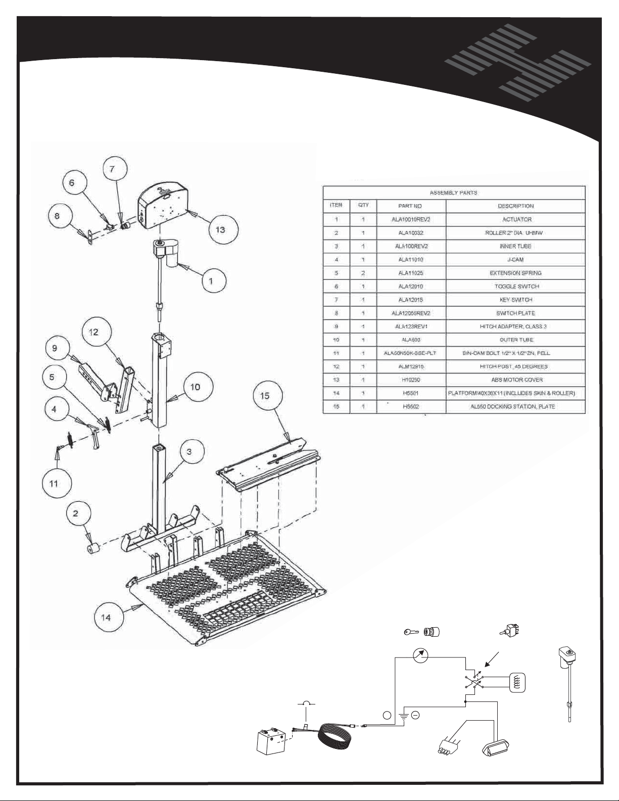
EXPLODED VIEW - AL-550
BATTERY
CIRCUIT
BREAKER
VEHICLE HARNESS
33
12V
+
KEYSWITCH
TRAILER PLUG
N
BROW
POLE REVERSING
SWITCH
MOTOR COVER
LIGHT
ACTUATOR
Page 34
Vehicle Hitch
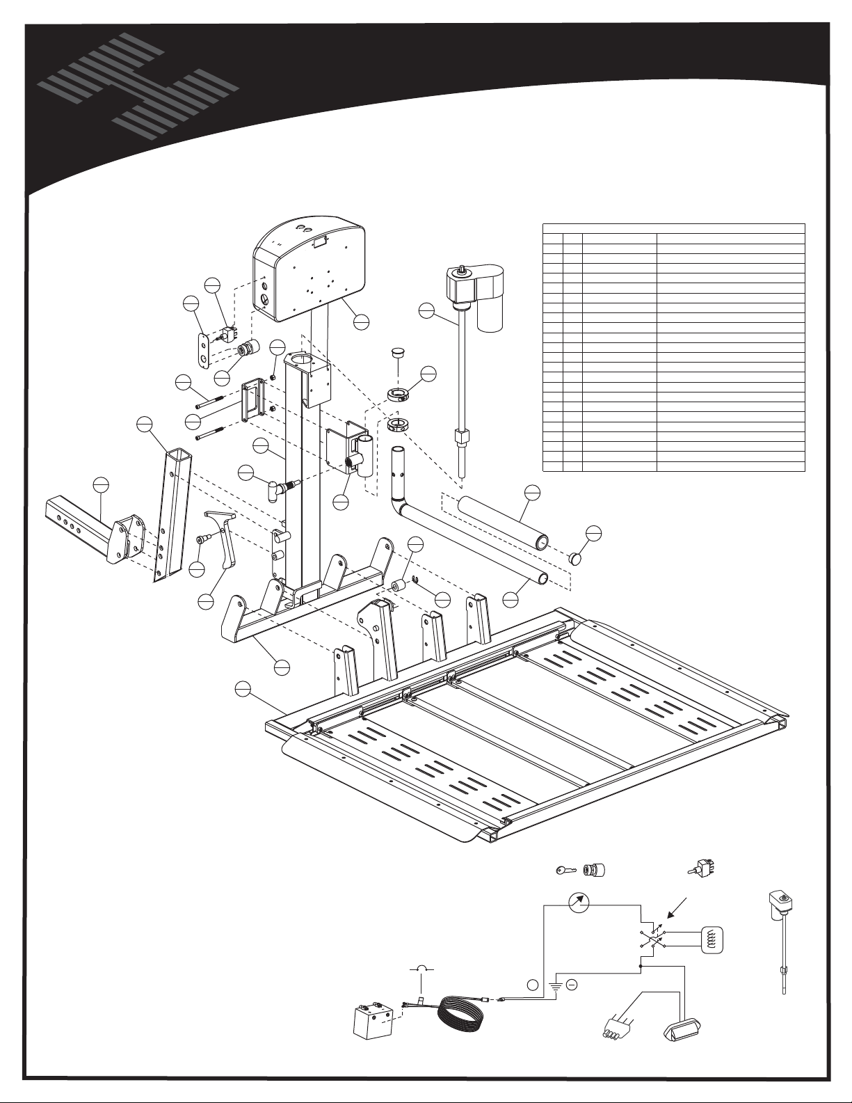
EXPLODED VIEW - AL-560
BATTERY
CIRCUIT
BREAKER
VEHICLE HARNESS
34
12V
+
KEYSWITCH
TRAILER PLUG
N
BROW
POLE REVERSING
SWITCH
MOTOR COVER
LIGHT
ACTUATOR
Page 35
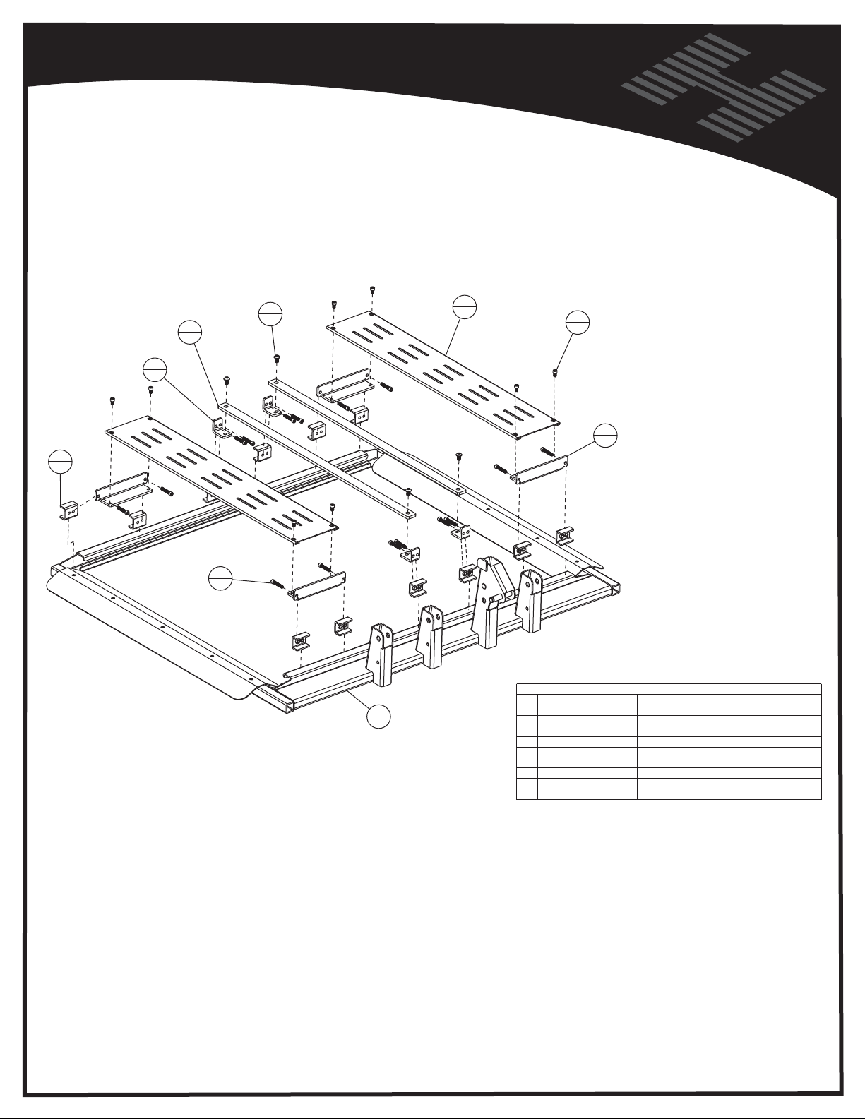
EXPLODED VIEW - AL-560
35
Page 36

Vehicle Hitch
HARMAR MOBILITY - 2075 47TH ST - SARASOTA, FL 34234 - 866.351.2776 - WWW.HARMAR.COM
 Loading...