

Page 1

harman/kardon
SUB-TS15
(HKTS 15 SUBWOOFER)
SERVICE MANUAL
harman/kardon, Inc.
250 Crossways Park Dr.
Woodbury, New York 11797 Rev0 2/2007
Page 2

SUB-TS15 harman/kardon
1
CONTENTS
BASIC SPECIFICATIONS . . . . . . . . . . . . ……………………………………. . . . 1
DETAILED SPECIFICATIONS. . . . . . . . . . . . . .. . . . . . . . . ………………….. …2
PACKAGING. . . . . . . . . . . . . .. . . . . . . ……………………… . . . . .. . .. .. .. . . . . 4
CONTROLS & CONNECTIONS . . . . . . . . . . . . . .. . . . . . . . . ………………….. 5
SPEAKER CONNECTIONS……………………….………..……. . . .. . .. . . . .. . .
OPERATION……. . . . . .. . . . . . . . .. .. . . . .. .. . . . . ………………………………10
TEST PROCEDURE. . . . . . . . . . . ………………………………………………….11
UNIT EXPLODED VIEW. . . . …………… ……………. .. ………... . . .. .. ... . … . 12
AMPLIFIER EXPLODED VIEW. . . . ………………... . .. ………... . . .. . . .. . .… . 13
BLOCK DIAGRAM . . . . . . . . . . . . . .. . . . . . . ……………… . . . . .. . .. . .. . . . . 14
DETAILED TROUBLESHOOTING..…………………………………………………16
PCB DRAWINGS. .. . . . . . . . . . . . . . .. . . . . ……… . …………. . . . .. .. .. . .. . . . 17
ELECTRICAL PARTS LIST …………. .... . .. . . . …………………………... … . . 23
SEMICONDUCTOR PINOUTS . . . .. .. .. .. . . . .. . ……………..………..………. .27
SCHEMATIC DIAGRAMS . . . . . . . . .. .. .. .. . . . .. . ………………………..……. .28
7
SPECIFICATIONS
Amplifier Power (RMS) 100 Watts
Driver 10" (254mm) woofer, Bass Reflex Enclosure
Inputs Stereo Line Level, dedicated Subwoofer (LFE)
and Speaker Level with gold-plated binding posts
Outputs Speaker Level with gold-plated binding posts
Frequency Response 35Hz – 120Hz (Filter switch ON)
35Hz – 450Hz (Filter switch OFF)
External Trigger Input Voltage: 3-30 Volts AC/DC
Dimensions (H x W x D) 18-7/8" x 13-3/8" x 13-3/8" (479mm x 340mm x 340mm)
Weight 35.11 lb/15.8kg
Occasional refinements may be made to existing products without notice but will always meet or exceed original specifications
unless otherwise stated.
Page 3

SUB-TS15 harman/kardon
2
SUB-TS
LINE VOLTAGE Yes/No Hi/Lo Line Nom. Unit Notes
Parameter
Amp Section
Type (Class AB, D, other) AB n/a
Load Impedance (speaker) 4 Ohms
Rated Output Power 100 Watts
THD @ Rated Power 0.08 %
THD @ 1 Watt 0.15 %
DC Offset 5 mV-DC
Damping factor >100 n/a
Input Sensitivity
Input Frequency 50 Hz
Line (L&R) Input 220 mVrms
SUB (LFE) Input 125 mVrms
Speaker/Hi Level Input 2.2 Vrms
Hi Level Max. Input Voltage 32 Vrms
Signal to Noise
SNR-A-Weighted 100 dB
SNR-unweighted 90 dB
SNR rel. 1W-unweighted 65 dB
Residual Noise Floor 1.2 mVrms
Residual Noise Floor 0.8 mVrms
15 100W Powered Sub/ Plate Amp
US 120vac/60Hz Yes 108-132 120 Vrms Normal Operation
Nonimal
Specification
Unit
QA Test
Limits
n/a
n/a
75
0.1
0.5
30
30
n/a
154 - 308
87 - 175
1.5 - 3.0
30
85
80
60
3.0
2.0
Conditions Notes
Nominal
50 - 250 Hz, 1 input driven, limiter off
22k filter
22k filter
@ Speaker Outputs
Measured at amplifier board
Nominal Freq.
To Rated Power Single input driven
To Rated Power SUB (LFE) input driven only
To Rated Power (20 dB below Line In), Single input driven
Nominal Freq., Min. Volume
relative to rated power A-Weighting filter
relative to rated power 22k filter
relative to 1W Output 22k filter
Volume @max, using RMS reading
DMM/VOM (or A/P)
Volume @max, w/ A/P Swept Bandpass
Measurement (Line freq.+ harmonics)
Measured at the speaker at speaker output
terminals on the amp board.
Input Impedance
Line Input (L, R,LFE) 10K ohms
Speaker/Hi Level Input 4.7K ohms
Filters
L&R Fixed Low-Pass Filter 170 Hz
SUB (LFE) Low pass Filter 270 Hz
Subsonic filter (HPF) 3rd Order 28 Hz
Limiter
THD at Max. Output Power
Features
Auto - On -Off Selection Switch YES
Phase Switch 0-180 deg
Filter On/Off Switch YES
Volume Pot Taper (Lin/Log) LOG
Speaker Out YES
2-Color LED power indicator YES
Power Switch YES
Fuse Holder YES
Input Configuration
Line In (L,R)
SUB (LFE) YES
Speaker/Hi Level In YES
Signal Sensing (ATO)
Auto-Turn-On (yes/no) YES
ATO Input test frequency 50 Hz
ATO Level Line & SUB Input 4.0 mV
ATO Level Speaker in 40 mV
ATO Turn-on time 5 ms
ATO Turn-OFF Time 15 minutes
2.0 %
YES
n/a
Nominal
n/a
Nominal
150 - 200
240 - 300
22 - 28
functional
functional
functional
functional
functional
functional Blue: On, Amber: Stand-by
functional
functional
functional Dual RCA jack
functional RCA jack
functional
functional
2.0 - 6.0
25 - 55
functional
10 - 20
@ -6dB ref. 100Hz
@ -3dB ref. 100Hz
@ -3dB ref. 30Hz
5.0
Auto - on selection switch in Auto
n/a
Auto - on selection switch in Auto
Auto - on selection switch in Auto
Auto - on selection switch in Auto
Amp connected and AC on, then input
signal applied
Time before muting, after signal is
removed
2nd order fixed
2nd order fixed
3rd order fixed
Refer to ATO section
A Taper
Binding post connector L&R
Binding post connector L&R
Power on Delay time 3 sec.
Transients/Pops
ATO Transient 5 mV-peak
Turn-on Transient 50 mV-peak
functional
10
100
AC Power Applied
@ Speaker Outputs
@ Speaker Outputs AC Line cycled from OFF to ON
Page 4
T
e
SUB-TS15 harman/kardon
3
Parameter
Turn-off Transient 50 mV-peak
Nonimal
Specification
Unit
QA Test
Limits
100
Conditions Notes
@ Speaker Outputs AC Line cycled from ON to OFF
Efficiency
Stand-by Input Power 10 Watts
Power Consumption @ rated pow
Protection
Short Circuit Protection YES
Thermal Protection YES
DC Offset Protection YES
Primary Fuse Rating
USA-Domestic (120V) 2.5 Amps
170 Watts
12
200
functional
functional
functional
n/a
Maximum allowable input power under nominal
input voltage and frequency, in stand-by mode (HO
@ nom. line voltage
@ nom. line voltage 100 Watts @ 4.0 ohms and nominal line voltage
Direct short at output
DC present at Speaker Out leads Relay or crowbar (for driver/fire protection),
Type-T or Slo Blo User-replacable fuse with UL/SEMCO rated holder.
or COLD operation).
Amplifier should resume operation after short circuit
condition is removed.
Any user accessible metal parts should always
remain at 65 degree C or less for domestic version
or 55 degree C or less for EU version.
Page 5
SUB-TS15 harman/kardon
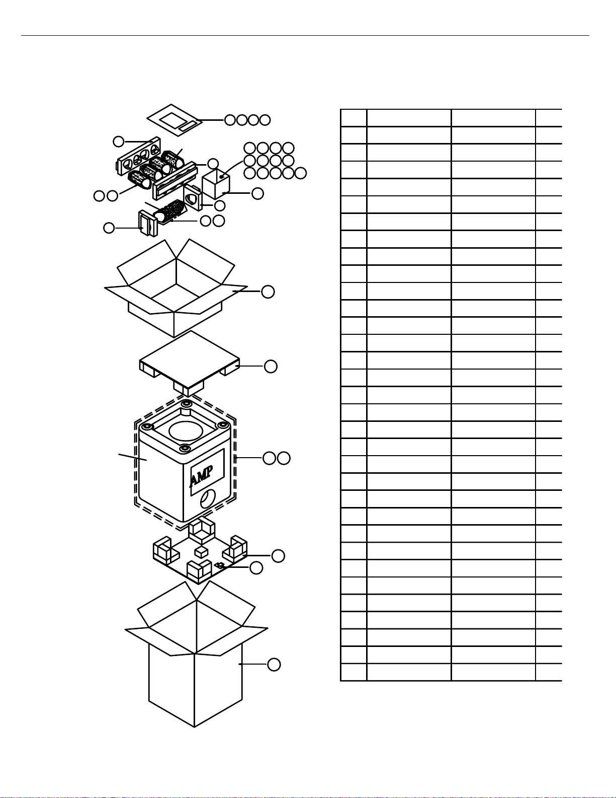
PACKAGE
7
SUB
Item
1 2 3 4
5
SAT
12 13 14 15
5
16 17 18 19
20 21 22 23 24
8
CEN
6
6
10
9
11
26
27
29 30
28
31
32
.
Description
1
Color Label
2
Warranty Card
3
Warranty Card
4
Owner's Manual
Packaging 1.0
5
Packaging 1.0
6
7
Non-woven Bag
PE Bag
8
Non-woven Bag
9
PE Bag
10
Cardboard
11
Wall Mounting Bracket 326-ABS-00108-0BAE 4.0
12
Mounting Plate
13
Leather Coaster for Sats
14
15
Metal Bracket (Center)
Screw Bag for
16
CEN Wall Bracket
17
Terminal Cap
18
15ft RCA Signal Cable
19
Speaker Cable 20ft. (Red)
Speaker Cable 20ft. (Grn)
20
Speaker Cable 20ft. (Wht)
21
Speaker Cable 12M (Gry)
22
Speaker Cable 12M (Blu)
23
Screw Bag for
S
24
SAT Wall Bracket
25
Signal Cable for Trigger
26
Inner Carton for Sat, Ctr
27
Top Packing
28
Bottom Packing
29
Non-woven Bag
30
PO Bag
31
Dessicant
32
Outer Carton 402-000-05679-E
Part Number
0
405-000-00333-E
405-000-05033-E
406-000-05503-E
E
1
2
4
4
326-FE-00109-E
336-EVA-05405-0BAE
325-SPCC-05229-0BAE 1.0
371-000-05168-E
317-PS-00172-0BAE
370-000-05034-E
370-000-05035-E
370-000-05036-E
370-000-05037-E
370-000-05038-E
370-000-05039-E
371-000-00360-E
165-54505501-e 1.0
401-000-00118-E
431-000-05919-E
431-000-05920-E
2
4
3
Qty
1.0
1.0
1.0
1.0
4.0
4.0
1.0
1.0
1.0
4.0
4.0
1.0
4.0
1.0
1.0
1.0
1.0
1.0
1.0
1.0
1.0
1.0
1.0
1.0
1.0
2.0
1.0
371-000-05168-E: 2pcs Flat head, 10mm( screw Length ) x 8mm(Screw head Dim.)
371-000-00360-E: 2pcs Round head, 1/4"( screw Length ) x 10.5mm(Screw head Dim.)
4
Page 6

SUB-TS15 SUBWOOFER AMPLIFIER PANEL CONTROLS AND CONNECTIONS
¡ Subwoofer-Level Control: Volume
may be adjusted using the Subwoofer-
Level Control. Turn the control clockwise
to increase the SUB-TS15’s volume, or
counterclockwise to decrease it.
™ High-Cut (Low-Pass) Filter Switch:
Placing this switch in the ON position activates circuitry that cuts out all audio input
signals above 120Hz. This allows the SUBTS15 to focus its power on reproducing the
low-frequency portion of the signal, avoiding
inefficiency and distortion. Engage this filter
when using the Speaker-Level Inputs ª,
or when using the Line-Level Full-Range
Inputs ¶, unless your receiver or processor
processes its line-level output using a lowpass filter. The filter has no effect when the
SUB Input § is used.
£ External Trigger Input: Use the sup-
plied mini-plug cable to connect the trigger
output of another compatible product to this
jack. Whenever a trigger signal between
3 and 30 volts (AC or DC) is detected, the
SUB-TS15 amplifier will turn on, even when
the Audio-Sense feature has been activated
by placing the Audio-Sense On/Off Switch
¢ in the AUTO position. The amplifier will
remain on for about 10–15 minutes without
a trigger signal.
¢ Audio-Sense On/Off Switch: When
placed in the AUTO position, and when the
Master Power Switch ‚ is turned on, the
SUB-TS15 will automatically turn itself on or
¡ Subwoofer-Level Control
™ High-Cut (Low-Pass) Filter Switch
£ External Trigger Input
¢ Audio-Sense On/Off Switch
∞ Phase Switch
§ Line-Level Subwoofer (SUB) Input
¶ Line-Level Full-Range Inputs
• Speaker-Level Outputs
ª Speaker-Level Inputs
‚ Master Power Switch
⁄ AC Power Cord
SUB-TS15 harman/kardon
5
Page 7

SUB-TS15 SUBWOOFER AMPLIFIER PANEL CONTROLS AND CONNECTIONS
place itself in the Standby mode, depending on
whether it is receiving an audio signal. When
this switch is placed in the ON position, the
SUB-TS15 will remain on, whether or not it is
receiving an audio signal.
An LED located on top of the SUB-TS15
indicates whether the SUB-TS15 is in the
ON or STANDBY state when used with the
Audio-Sense On/Off Switch ¢ in the
AUTO position. The LED is lit blue to indicate that the SUB-TS15 is receiving an
audio signal and is turned on, and the LED
is lit amber to indicate that no signal is
being received and the SUB-TS15 is in
Standby mode.
When the Audio-Sense On/Off Switch ¢
is in the ON position, the LED will be
lit blue, whether or not an audio signal is
present.
When the Master Power Switch ‚ is
turned off, the LED goes dark, no matter
which position the Audio-Sense On/Off
Switch ¢ is in.
∞ Phase Switch: This switch determines
whether the SUB-TS15 subwoofer’s pistonlike action moves in and out in phase with
the main speakers. If the speakers were to
play out of phase, the sound waves produced by the subwoofer would be cancelled
out, reducing bass response. This phenomenon depends in part on the relative placement of the speakers in the room. In most
cases, the Phase Switch ∞ should be left
in the NORMAL position. However, it
does no harm to experiment with the Phase
Switch ∞, and you may leave it in the
position that maximizes bass response.
§ Line-Level Subwoofer (SUB) Input:
Connect the subwoofer output of a receiver
with digital surround sound decoding, such
as Dolby
®
Digital or DTS,®to this input. This
input bypasses the SUB-TS15’s internal
crossover circuitry, and should only be used
with a filtered signal. If your receiver does not
have digital decoding, you should use the
Line-Level Full-Range Inputs ¶ instead.
¶ Line-Level Full-Range Inputs: Connect
the line-level subwoofer output or preamp output(s) of your receiver or amplifier to these
inputs. If your receiver does not have a separate subwoofer output, use a Y-adapter (not
supplied) to bridge the receiver’s preamp output to the main amp input for that channel,
and connect the long end of the adapter
to the corresponding line-level input on the
SUB-TS15. If your receiver has only a single
subwoofer output, you may connect it to
either the left or right line-level input on the
SUB-TS15, and no Y-adapter is needed.
• Speaker-Level Outputs: If you are
using the Speaker-Level Inputs ª on the
SUB-TS15, you should connect these binding-post terminals to your front left and right
speakers, remembering to maintain polarity
by connecting the (+) terminal on the SUBTS15 subwoofer to the (+) terminal on the
speaker, and the (–) terminal on the SUBTS15 subwoofer to the (–) terminal on the
speaker. If you are not using the Speaker-
Level Inputs ª, then connect your front
left and right speakers directly to your receiver
or amplifier. See pages 9 through 12 for
further information on speaker connections.
ª Speaker-Level Inputs: If your receiver
or amplifier does not have a line-level subwoofer output, connect these binding-post
terminals to the main left and right speaker
terminals of your receiver or amplifier.
Remember to maintain polarity by connecting
the (+) terminal on the receiver/amplifier to the
(+) terminal on the SUB-TS15 subwoofer, and
the (–) terminal on the receiver/amplifier to the
(–) terminal on the SUB-TS15 subwoofer.
‚ Master Power Switch: Place this
switch in the “•” position to power-on the
SUB-TS15 subwoofer. The SUB-TS15 will
then be either in the Standby mode or completely on, depending on the position of the
Audio-Sense On/Off Switch ¢.
⁄ AC Power Cord: Make sure to plug this
cord into an active, unswitched electrical outlet for proper operation of the SUB-TS15.
The cord should not be plugged into the
accessory outlets found on some audio
components.
SUB-TS15 harman/kardon
6
Page 8
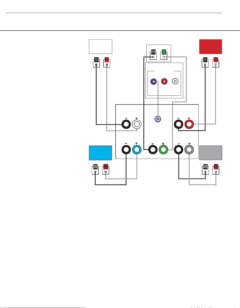
Dolby®Digital or DTS®(or Other
Digital Surround Mode) Connection
USE THIS INSTALLATION METHOD FOR
DOLBY DIGITAL, DTS OR OTHER DIGITAL
SURROUND PROCESSORS:
Use the line-level input jack marked SUB
§ for the Low-Frequency Effects channel.
Connect this jack to the subwoofer output
or LFE output on your receiver or amplifier.
Connect each speaker to the corresponding
speaker terminals on your receiver or
amplifier.
Make sure you’ve configured your surround
sound processor for “Subwoofer On.” The
front left, front right, center and surround
speakers should all be set to “Small.”
When all connections have been made, plug
the AC power cord on the subwoofer into
an AC outlet.
SPEAKER CONNECTIONS
SUB-TS15 harman/kardon
7
Front
Left
– +
Surround
Left
– +
Front
Left
Surround
Left
Center
– +
SUB-TS15 Subwoofer
LINE LEVEL IN
SUB
SUB/LFE
Out
Center
Receiver
L
R
Surround
Front
Right
– +
Front
Right
Right
Surround
Right
– +
Page 9
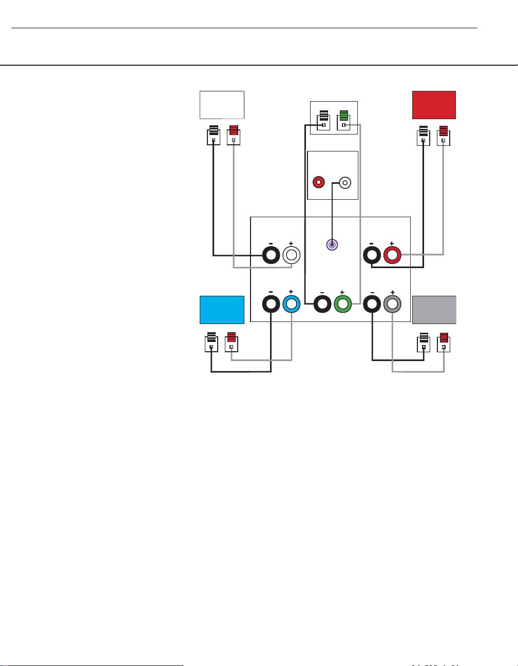
SPEAKER CONNECTIONS 11
Dolby Pro Logic
®
(Non-Digital) – Line Level
USE THIS INSTALLATION METHOD FOR
DOLBY PRO LOGIC APPLICATIONS (NOT
DOLBY DIGITAL, DTS OR OTHER DIGITAL
PROCESSING), WHERE THE RECEIVER/
PROCESSOR IS EQUIPPED WITH A SUBWOOFER OUTPUT, OR A VOLUMECONTROLLED PREAMP (LINE-) LEVEL
OUTPUT:
Use the supplied RCA-type interconnect
cable to connect the
line-level subwoofer
output on your receiver
or amplifier to either
the left or right Line-Level Full-Range
Input ¶ on the SUB-TS15 subwoofer.
Use both the left and right inputs on the
subwoofer if your receiver or processor has
both left and right line-level outputs. In that
case, you will need to supply a second
interconnect cable.
If your receiver is equipped with line-level outputs but does not have a separate subwoofer
output, use a Y-adapter (not supplied) to
bridge the receiver’s preamp output to the
main amp input for that channel, and connect
the long end of the adapter to the corresponding line-level input on the SUB-TS15.
IMPORTANT: Do not use the SUB Input
§ on the subwoofer with Dolby Pro Logic
processors.
If your receiver/processor has a built-in lowpass-crossover filter for the subwoofer output, you may use the SUB Input § to
bypass the subwoofer’s internal crossover.
Connect each speaker to the corresponding
speaker terminals on your receiver or amplifier.
Make sure that you have configured your
surround sound processor for “Subwoofer
On.” The front left, front right, center and
surround speakers should all be set to
“Small.”
When all connections have been made, plug
the AC power cord on the subwoofer into
an AC outlet.
SPEAKER CONNECTIONS
SUB-TS15 harman/kardon
8
Front
Left
– +
Surround
Left
– +
Front
Left
Surround
Left
Center
– +
SUB-TS15
Subwoofer
Line-Level
R
SUB/LFE
Out
Center
Receiver
Front
Right
– +
L
Front
Right
Surround
Right
Surround
Right
– +
Page 10
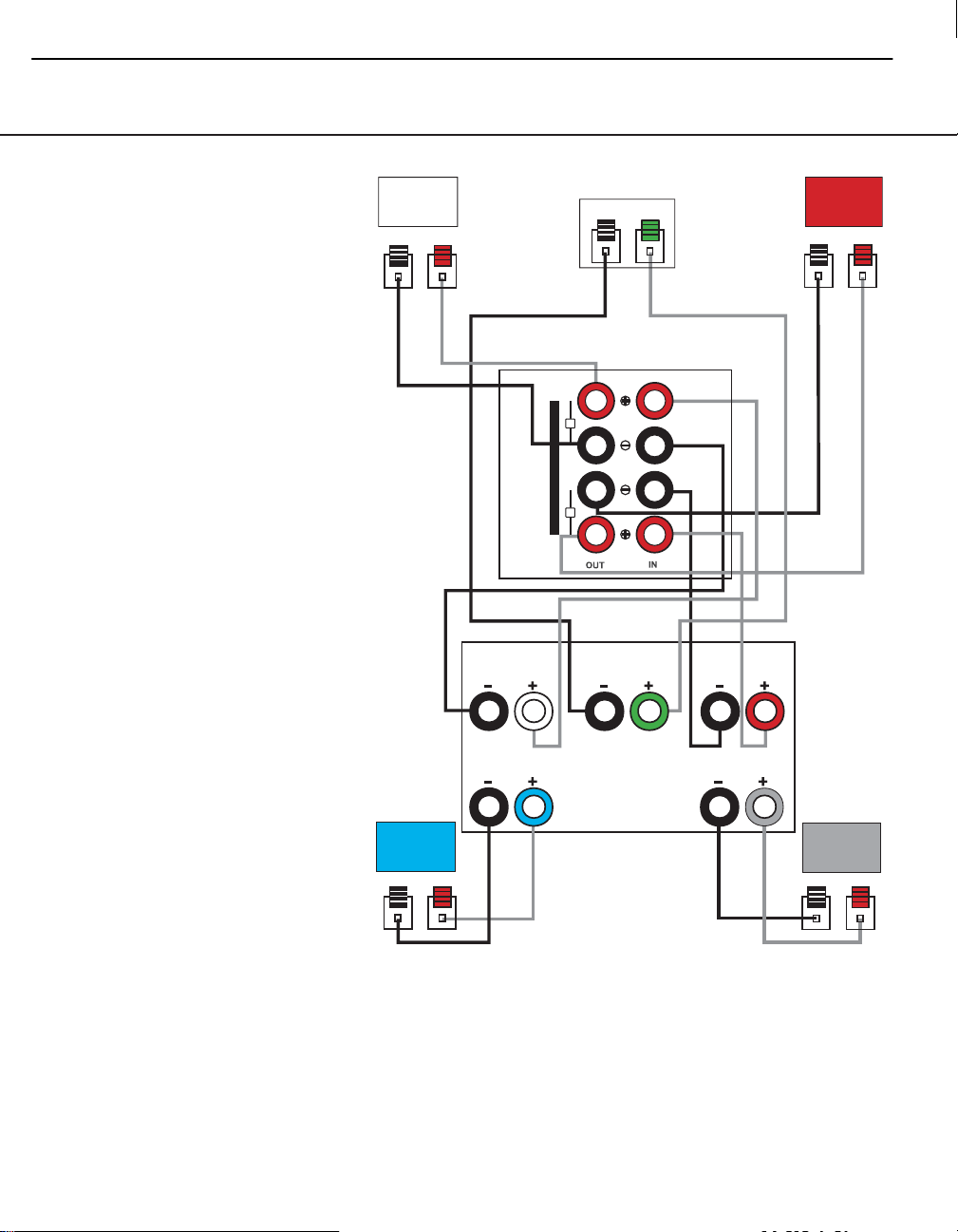
SPEAKER CONNECTIONS
Dolby Pro Logic
(Non-Digital) – Speaker Level
USE THIS INSTALLATION METHOD FOR
DOLBY PRO LOGIC APPLICATIONS (NOT
DOLBY DIGITAL, DTS OR
OTHER DIGITAL
PROCESSING), WHERE THE RECEIVER/
PROCESSOR DOES NOT HAVE A SUBWOOFER OUTPUT, OR A VOLUMECONTROLLED PREAMP (LINE-) LEVEL
OUTPUT:
Connect your receiver or amplifier’s front
left and right speaker terminals to the left
and right Speaker-Level Input ª terminals on the SUB-TS15 subwoofer that are
marked “High Level In.” Connect the left and
right Speaker-Level Output • terminals
on the SUB-TS15 subwoofer that are
marked “High Level Out” to the corresponding terminals on
the back of your front
left and right speakers.
Connect your receiver or amplifier’s center
and surround left and right speaker terminals to the corresponding terminals on the
back of your center, and surround left and
right speakers.
When all connections have been made,
plug the AC power cord on the subwoofer
into an AC outlet.
SUB-TS15 harman/kardon
9
Front
Left
Center
– +
Front
Right
– + – +
SUB-TS15
Subwoofer
L
H
I
G
H
L
E
V
E
L
R
Receiver
Front Left
Surround Left
Center
Front Right
Surround Right
Surround
Left
Surround
Right
– + – +
Page 11

OPERATION
Move the Master Power Switch ‚
(marked Power) to the “•” (On) position.
The SUB-TS15 subwoofer will automatically turn itself on or go into Standby mode,
depending on whether or not a signal is
being sent to it by your receiver or surround
processor, and provided that the Audio-
Sense On/Off Switch ¢ is moved down
so that it is in the AUTO position.
When your receiver or amplifier is off, or is
not sending program material to the subwoofer, the subwoofer will be in Standby
mode and the LED Indicator on the top of
the subwoofer will turn amber. When the
sub
woofer senses an audio signal,
it will
automatically turn itself on and the LED
Indicator will turn blue. If the subwoofer does
not sense a signal after
approximately twenty
minutes,
it will automatically go into Standby
mode.
When the Audio-Sense On/Off Switch ¢
is switched to the ON position, the subwoofer will remain on, whether or not
program material is playing, and the LED
Indicator will remain lit blue.
If your receiver, processor or amplifier is
equipped with a compatible trigger output,
you may connect it to the SUB-TS15’s
External Trigger Input £. When you turn
on your component, if you have set it up correctly, it will send an electrical trigger signal
to the SUB-TS15, which will cause the
subwoofer to turn itself on, even when the
Audio-Sense On/Off Switch ¢ has been
placed in the AUTO position and no audio
signal is detected.
The trigger signal must be between 3 and 30
volts, although it may be an AC or DC signal,
and an AC signal may be 50Hz or 60Hz.
If you’ll be away from home for an extended
period of time, or if the subwoofer will not be
used, switch the Master Power Switch ‚
to the OFF position.
Volume
Volume can be adjusted using the
Subwoofer-Level Control ¡, as
shown. Turn the control knob clockwise
to increase the volume of the subwoofer,
and counterclockwise to decrease the
subwoofer’s volume.
Additional Bass Adjustments
In addition to the volume adjustments
described above, the SUB-TS15 subwoofer
includes a Phase Switch ∞ and a Filter
Switch ™ that can be used to adjust the
bass response to suit your listening environment or taste.
In most situations, the Phase Switch ∞
should be left in the NORMAL position.
If you suspect that the subwoofer is playing
out of phase with the other speakers, which
would tend to diminish bass response, try
placing this switch in the REVERSE
position. There is no harm in experimenting,
and you may return the switch to the
NORMAL position at any time. If you
rearrange your room and reposition the
speakers, it would be a good idea to check
whether they are in phase by flipping this
switch.
The High-Cut (Low-Pass) Filter Switch
™ limits the frequencies of the audio signal
inputted to the subwoofer to the low frequencies that the subwoofer reproduces
best. This allows the subwoofer to perform
more efficiently, and with superior bass
reproduction, minimizing distortion that might
occur if the subwoofer attempted to reproduce higher frequencies. This switch should
be left in the ON position, except:
1. When the SUB Input § is being used,
in which case it has no effect, or
2. When the Speaker-Level Inputs ª or
the Line-Level Full-Range Inputs ¶ are
being used with a crossover or filter aboard
the receiver or processor.
In these two circumstances, place the switch
in the OFF position.
MIN MAX
Subwoofer
Level
MIN MAX
Subwoofer
Level
SUB-TS15 harman/kardon
10
Page 12

SUB-TS15 harman/kardon
11
Test Set Up and Procedure
Equipment needed:
• Function/signal generator/sweep generator
• Integrated Amplifier
• Multimeter
• Speaker cables
Initial Control Settings:
• Power Switch OFF; Filter OFF
• Level MIN (Full CCW)
• Phase, Auto/On switches do not matter
General Unit Function (UUT = Unit Under Test)
1) From the signal generator, connect one line level (RCA) cable to the Subwoofer Line Level Input jacks L/R
on the UUT. Use a Y-cable from a mono source if necessary to connect to both inputs. Do not connect to
the single, purple SUB input.
2) Turn on generator; adjust to 75mV, 50 Hz .
3) Plug in UUT; turn the power switch ON. Turn LEVEL control full clockwise (MAX)
4) LED should turn from Amber to Blue (on top of UUT); immediate and vigorous bass response should be
heard and felt from port tube opening.
5) Turn off generator, turn LEVEL control full counterclockwise (MIN), and disconnect RCA cable.
6) Connect one pair
of speaker cables to Speaker Level input terminal (IN) on UUT. Cables should be
connected to an integrated amplifier fed by the signal generator.
7) Turn on generator and adjust so that speaker level input at the amplifier is 1.6V, 50 Hz. Turn LEVEL control
full clockwise.
8) LED should turn from Amber to Blue; immediate and vigorous bass response should be heard and felt from
the port tube opening.
Sweep Function
1) Follow steps 6-8 above, using a sweep generator as a signal source.
2) Sweep generator from 20Hz to 300Hz. Listen to the cabinet and drivers for any rattles, clicks, buzzes or
any other noises. If any unusual noises are heard, remove woofers and test.
Driver Function
1) Remove woofer from cabinet; detach + and - wire clips.
2) Check DC resistance of woofer; it should be 3. 0 ohms ±10%
3) Connect a pair of speaker cables to driver terminals. Cables should be connected to an integrated amplifier
fed by a signal generator. Turn on generator and adjust so that speaker level output is 5.0V.
4) Sweep generator from 20Hz to 1kHz. Listen to driver for any rubbing, buzzing, or other unusual noises.
Page 13
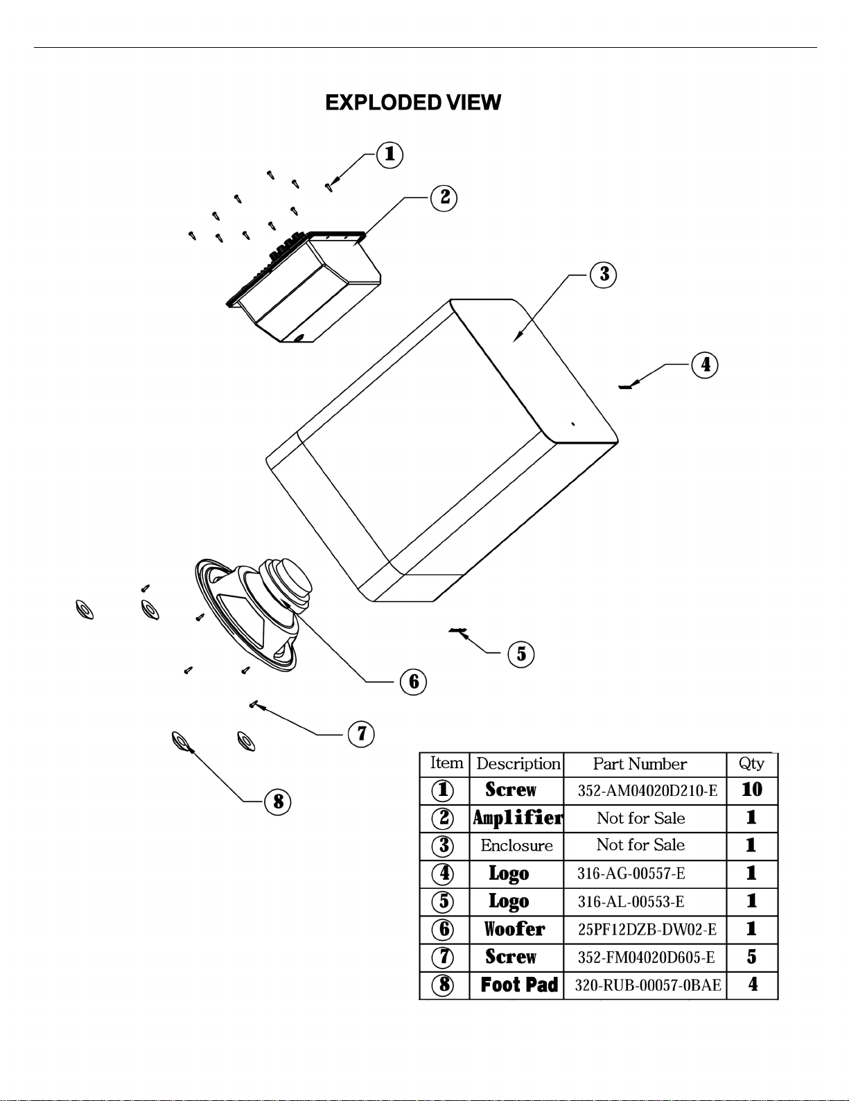
SUB-TS15 harman/kardon
12
Page 14

SUB-TS15 harman/kardon
13
Page 15

SUB-TS15 harman/kardon
14
Page 16

SUB-TS15 harman/kardon
15
Page 17

SUB-TS15 harman/kardon
16
SUB-TS15 (UL) AMP
Troubleshoot i ng Flow Chart
AMP no signal out
no
yes
DC voltage check ±Vcc
Check Fuse,Transformer,
D110, etc
yes
yes no
Check+/-15VDC
Check Q117,118, 119,D109 etc
yes
yes
LED red
LED light green or red
Check,Q206,Q207,U203 etc
LED light green yes yes
no
Check U202 pin14 signal
yes yes no
Check U201
pin14 signal
CheckU201,U202,VR201
VR202. etc
no
Check limiter board C304
Check U301,R343,R344 ,
C340,Q301,Q302, etc
yes
ye s yes
no
Test R121,R122 signal
Check ,+VCC& -VCC
DC voltage
Check J123,J124 etc
no
yes yes
Check RY101, D102, Q113,Q114 etc
Check Q107,Q108,Q105,
Q106,Q103,Q104,U101,etc
yes
no
Check U101,Q115,Q116,R138 etc
yes
Set R138 to R140’S
Voltage is 0.51VDC
yes
Check P102 signal
The Amp Ass ’y OK, END
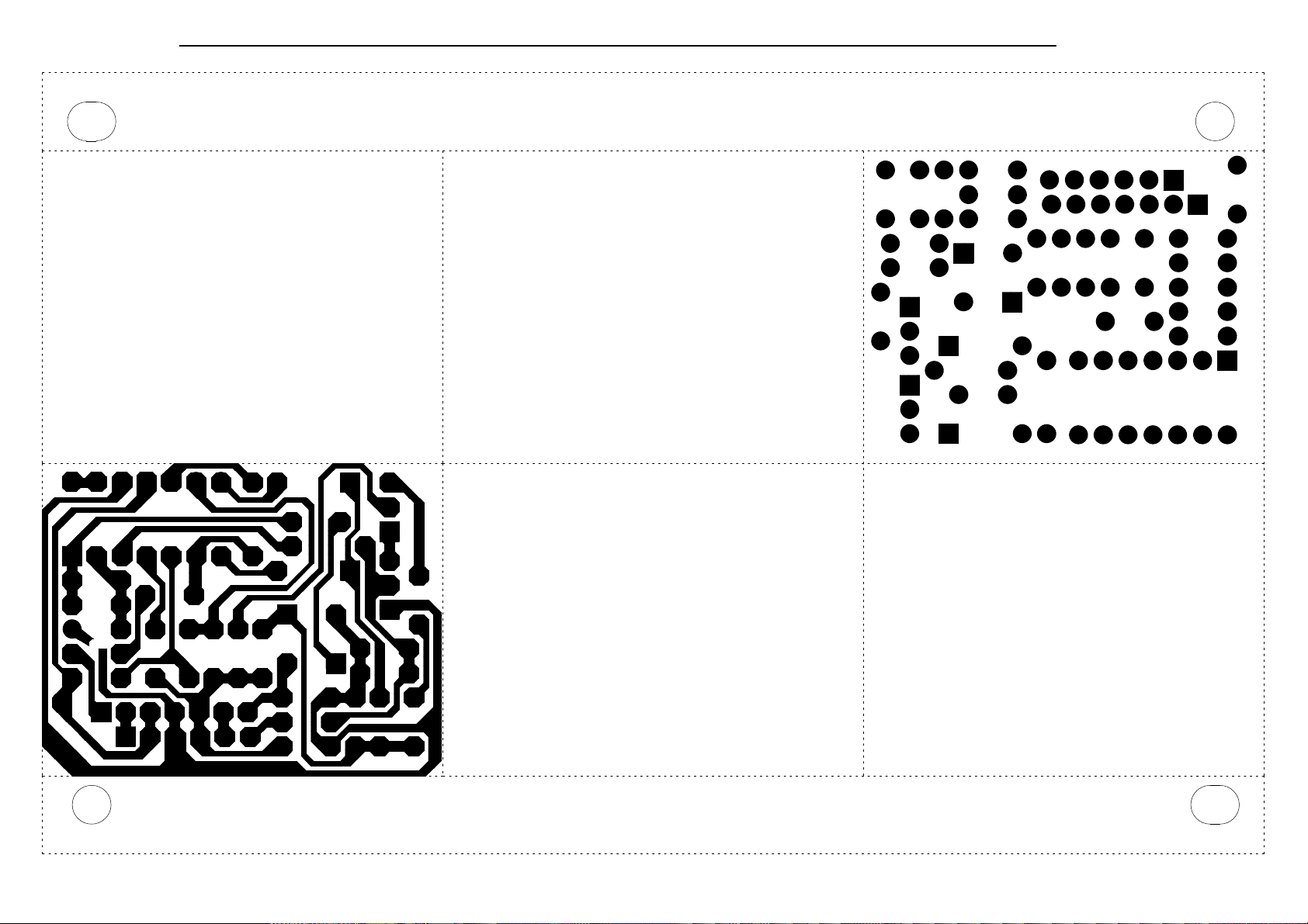
Page 18

SUB-TS15 harman/kardon
17
Page 19

SUB-TS15 harman/kardon
18
Page 20

SUB-TS15 harman/kardon
19
Page 21
SUB-TS15 harman/kardon
20
Page 22

SUB-TS15 harman/kardon
21
Page 23

SUB-TS15 harman/kardon
22
Page 24

P
V
SUB-TS15 harman/kardon
23
SUB-TS15 120V Electrical parts list
Part number Description Qty Reference Designator
MAIN/POWER PCB
Resistors
110-10821jk2-e Resistor 820Ω 1W ±5% jam crus and shaping 10mm (RoHS) 1 R132
110-122r2j15-e Resistor 2.2Ω 1/2W ±5% prone short crus 15mm (RoHS) 1 R127
110-20331jk2-e Resistor 330Ω 2W ±5% jam crus and shaping 5mm (RoHS) 2 R146,R149
113-50r10j10-e cement Resistor 0.1Ω 5W ±5% standing (RoHS) 2 R121,R122
114-03302m0-e semi-fixed Resistor 3K 0.3W ±20% (RoHS) 1 R138
110-14472j26-e Resistor 4.7K 1/4W ±5% CF 26mm (RoHS) 2 R147,R150
110-14681j26-e Resistor 680Ω 1/4W ±5% CF 26mm (RoHS) 2 R148,R151
110-16101j26-e Resistor 100Ω 1/6W ±5% CF 26mm 1 R120
110-16102j26-e Resistor 1K 1/6W ±5% CF 26mm (RoHS) 1 R124
110-16103j26-e Resistor 10K 1/6W ±5% CF 26mm (RoHS) 1 R134
110-16105j26-e Resistor 1M 1/6W ±5% CF 26mm (RoHS) 1 R143
110-16123j26-e Resistor 12K 1/6W ±5% CF 26mm (RoHS) 2 R135,R139
110-16152j26-e Resistor 1.5K 1/6W ±5% CF 26mm (RoHS) 6 R103,R123,R136,R137,R141,R142
110-16153j26-e Resistor 15K 1/6W ±5% CF 26mm (RoHS) 4 R118,R145,R152,R154
110-16154j26-e Resistor 150K 1/6W ±5% CF 26mm (RoHS) 1 R131
110-16181j26-e Resistor 180Ω 1/6W ±5% CF 26mm (RoHS) 2 R111,R114
110-16182j26-e Resistor 1.8K 1/6W ±5% CF 26mm (RoHS) 1 R153
110-16223j26-e Resistor 22K 1/6W ±5% CF 26mm (RoHS) 3 R128,R129,R133
110-16332j26-e Resistor 3.3K 1/6W ±5% CF 26mm (RoHS) 3 R106,R107,R144
110-16392j26-e Resistor 3.9K 1/6W ±5% CF 26mm (RoHS) 2 R105,R108
110-16393j26-e Resistor 39K 1/6W ±5% CF 26mm (RoHS) 1 R126
110-16470j26-e Resistor 47Ω 1/6W ±5% CF 26mm (RoHS) 4 R112,R113,R115,R116
110-16471j26-e Resistor 470Ω 1/6W ±5% CF 26mm (RoHS) 1 R140
110-16472j26-e Resistor 4.7K 1/6W ±5% CF 26mm (RoHS) 3 R110,R125,R130
110-16473j26-e Resistor 47K 1/6W ±5% CF 26mm (RoHS) 1 R101
110-16560j26-e Resistor 56Ω 1/6W ±5% CF 26mm (RoHS) 1 R117
110-16563j26-e Resistor 56K 1/6W ±5% CF 26mm (RoHS) 1 R104
110-16682j26-e Resistor 6.8K 1/6W ±5% CF 26mm (RoHS) 1 R109
Capacitors
130-2b102k503-e DISC Capacitor 1000P 50V ±10% (RoHS) 1 C116
130-3f104z503-e DISC Capacitor 0.1U 50V +80/-20% (RoHS) 4 C108,C113,C115,C119
130-3f473m503-e DISC Capacitor 0.047U 50V ±20% (RoHS) 1 C106
130-sl101k503-e DISC Capacitor 100P 50V SL ±10% (RoHS) 2 C139,C140
132-104j503-e MYLAR Capacitor 0.1U 50V ±5% (RoHS) 1 C107
132-223ja03-e MYLAR Capacitor 0.022uF 100V ±5% (RoHS) 4 C124,C125,C126,C128
135-3105m50-e Electrolytic CAP. 1U 50V ±20% (RoHS) 2 C105,C112
135-3107m16-e Electrolytic CAP. 100uF 16V ±20% (RoHS) 3 C109,C117,C120
135-3226m50-e Electrolytic CAP. 22U 50V ±20% (RoHS) 2 C114,C118
135-3227m10-e Electrolytic CAP. 220U 10V ±20% (RoHS) 2 C129,C130
135-3227m16-e Electrolytic CAP. 220U 16V ±20% (RoHS) 1 C111
135-3476m25-e Electrolytic CAP. 47U 25V ±20% (RoHS) 1 C103
130-3f472md00-e DISC Capacitor 4700P 400V ± 20% safe rule long crus (RoHS) 1
132-223ja03-e MYLAR Capacitor 0.022uF 100V ±5% (RoHS) 2 C123,C127
135-3107m16-e Electrolytic CAP. 100uF 16V ±20% (RoHS) 1 C110
135-4688m50-e Electrolytic CAP. 6800U/50V ±20% D25X45mm (RoHS) 2 C121,C122
Semiconductors
192-027c1815gr-e
192-028a1015gr-e
192-1572n5551-e
192-1582n5401-e
197-631n4148-e DIODE 500mW 75V 1N4148 Panjit (RoHS) 4 D101,D103,D105,D108
199-65000333g-e ZENER DIODE GDZJ3.3A 500mW 3.3V 2% 26mm (RoHS) 1 D102
199-65000623g-e ZENER DIODE GDZJ6.2B 500mW 6.2V 26mm 2% (RoHS) 2 D106,D107
Transistor 2SC1815GR NPN
Transistor 2SA1015GR PN
Transistor 2N5551 NPN
Transistor 2N5401 AI-PNP 350
for Power Switch SW100
5 Q102,Q111,Q112,Q113,Q118
2 Q114,Q116
2 Q103,Q109
2 Q104,Q110
Page 25

p
S
s
SUB-TS15 harman/kardon
24
Part number Description Qty Reference Designator
MAIN/POWER PCB
199-65001603g-e ZENER DIODE GDZJ16C 500mW 16V 26mm 2% (RoHS) 1 D109
190-06m4558d-e
192-021tip35c-e
192-022tip36c-e
192-027c1815gr-e
192-201d882y-e
192-202b772y-e
192-991d669a-e
192-992b649t-e
197-00kbl405-e bridge rectifier 4A 500V KBL405 (RoHS) 1 D110
197-101n4002-e diode 1N4002TB (RoHS) 1 D104
Miscellaneous
162-10202001-e single wire 26AWG 1007 200mm RED 3mm (RoHS) 1
171-udhss124d-e relay 5A 24V UDH-SS124D (RoHS) 1 RY101
175-1c07v01-e WIRE CONNECTOR & BASE 7PIN PITCH=2.5mm (RoHS) 1 P101
175-1d02v01-e WIRE CONNECTOR & BASE 2PIN PITCH=3.96mm (RoHS) 1 P102
175-1d03v01-e WIRE CONNECTOR & BASE 3 PIN PITCH=3.96mm JST-VH (RoH
193-3m2520-e * INSULATOR TO-3P 25x20mm (RoHS) 2 for Q107,Q108
323-AL-00020-0LAE HEAT SINK 65*32*31 aluminium color 1
351-AM03014A094-E M3*14 machine screw electrical black (RoHS) 1
352-AM03008D040-E ¢3*8 B type ping screw electrical black (RoHS) 4
361-FE-00051-0LAE TRANSISTOR stator 14.2*8.0*5.2t=1.6mm (RoHS) 1
361-NYL-00054-0LAE TRANSISTOR insulating mat (SW06002) (RoHS) 2
I.C. OPA 4558D Dual Op-Am
Transistor TIP35C NPN
Transistor TIP36C PNP
Transistor 2SC1815GR NPN
Transistor KSD882Y NPN
Transistor KSB772Y PNP
TransistorHI-SINCERITY HSD669A NPN
Transistor HSB649T PNP
1 U101
1 Q107
1 Q108
2 Q101,Q115
1 Q117
1 Q119
1 Q106
1 Q105
1 P103
PREAMP PCB
Resistors
110-12472j52-e Resistor 4.7K 1/2W ±5% CF 52mm (RoHS) 2 R201,R202
110-16102j26-e Resistor 1K 1/6W ±5% CF 26mm (RoHS) 6 R213,R214,R215,R254,R253,R304
R209,R212,R216,R217,R218,R220,R221,
110-16103j26-e Resistor 10K 1/6W ±5% CF 26mm (RoHS) 19
110-16104j26-e Resistor 100K 1/6W ±5% CF 26mm (RoHS) 5 R231,R263,R266,R257,R300
110-16105j26-e Resistor 1M 1/6W ±5% CF 26mm (RoHS) 1 R259
110-16113j26-e Resistor 11K 1/6W ±5% 26mm (RoHS) 1 R268
110-16122j26-e Resistor 1.2K 1/6W ±5% CF 26mm (RoHS) 1 R265
110-16123j26-e Resistor 12K 1/6W ±5% CF 26mm (RoHS) 1 R227
110-16124j26-e Resistor 120K 1/6W ±5% CF 26mm (RoHS) 1 R233
110-16152j26-e Resistor 1.5K 1/6W ±5% CF 26mm (RoHS) 1 R302
110-16183j26-e Resistor 18K 1/6W ±5% CF 26mm (RoHS) 1 R262
110-16203j26-e Resistor 20K 1/6W ±5% CF 26mm (RoHS) 2 R237,R238
110-16223j26-e Resistor 22K 1/6W ±5% CF 26mm (RoHS) 6 R247,R255,R256,R249,R250,R261
110-16303j26-e Resistor 30K 1/6W ±5% CF 26mm (RoHS) 2 R223,R224
110-16472j26-e Resistor 4.7K 1/6W ±5% CF 26mm (RoHS) 3 R200,R207,R258
110-16473j26-e Resistor 47K 1/6W ±5% CF 26mm (RoHS) 2 R219,R264
110-16474j26-e Resistor 470K 1/6W ±5% CF 26mm (RoHS) 1 R251
110-16475j26-e Resistor 4.7M 1/6W ±5% CF 26mm (RoHS) 1 R303
110-16512j26-e Resistor 5.1K 1/6W ±5% CF 26mm (RoHS) 2 R210,R211
110-16684j26-e Resistor 680K 1/6W CF 26mm (RoHS) 1 R252
110-16752j26-e Resistor 7.5K 1/6W ±5% CF 26mm TA (RoHS) 1 R234
110-16913j26-e Resistor 91K 1/6W ±5% CF 26mm (RoHS) 4 R203,R204,R205,R206
116-169091f26-e metal film Resistor 9.09K 1/6W±1% MF 26mm (RoHS) 1 R301
115-h503a102-e variable Resistor RV16AE-20B2-15K-A54-104(A50K) LEVEL 1 VR201
116-201001j5vx-e metalized oxide film Resistor 1K 2W ±5% 5mm (RoHS) 1 R267
R222,R225,R228,R229,R230,R232,R235,
R240,R248,R260,R270,R226
Capacitor
129-a154j633-e METALIZE CAP. 0.15U 63V ±5% MSC (RoHS) 2 C221,C222
Page 26

s
S
p
s
s
SUB-TS15 harman/kardon
25
Part number Description Qty Reference Designator
PREAMP PCB
129-a224j633-e METALIZE CAP. 0.22uF 63V ±5% MSC (RoHS) 1 C218
130-2b103k503-e DISC Capacitor 0.01u 50V ±10% (RoHS) 1 C238
130-2b221k503-e DISC Capacitor 220P 50V ±10% (RoHS) 12
130-3f104z503-e DISC Capacitor 0.1U 50V +80/-20% (RoHS) 8
132-183j503-e MYLAR Capacitor 0.018uF 50V ±5% (RoHS) 1 C223
132-223ja03-e MYLAR Capacitor 0.022uF 100V ±5% (RoHS) 1 C215
132-473j503-e MYLAR Capacitor 0.047U 50V ±5% (RoHS) 1 C224
132-563j503-e MYLAR Capacitor 0.056U 50V ±5% (RoHS) 1 C216
132-823j503-e MYLAR Capacitor 0.056U 50V ±5% (RoHS) 1 C217
135-3105m50-e Electrolytic CAP. 1U 50V ±20% (RoHS) 1 C228
135-3106m50-e Electrolytic CAP. 10uF 50V ±20% (RoHS) 12
135-3107m16-e Electrolytic CAP. 100uF 16V ±20% (RoHS) 1 C234
135-3226m50-e Electrolytic CAP. 22U 50V ±20% (RoHS) 1 C225
135-3475m16-e Electrolytic CAP.4.7U 16V ±20% (RoHS) 1 C233
135-3107m50-e Electrolytic CAP. 100U 50V ±20% (RoHS) 1 C301
135-3227m50-e Electrolytic CAP. 220uF 50V ±20% (RoHS) 1 C300
Semiconductor
C200,C204,C205,C207,C208,C210,C211,
C212,C214,C220,C230,C237
C232,C242,C244,C245,C246,C252,C254,
C256
C201,C202,C206,C213,C219,C231,C241,
C243,C251,C253,C248,C247
192-027c1815gr-e
197-631n4148-e DIODE 500mW 75V 1N4148 Panjit (RoHS) 13
199-65000513g-e ZENER DIODE GDZJ5.1B 500mW 5.1V 2% ROHM 1N5231B(RoH
190-06m4558d-e I.C. OPA 4558D dual inline (RoHS) 1 U203
190-06m4558ld-e I.C. NJRC NJM4558LD singlerow inline (RoHS) Dual Op-amp 1 U204
190-16tl074cn-e
197-141n4004-e *DIODE 1N4004 shaping short crus (RoHS) 4 D217,D218,D219,D220
190-05ps25051-e photoelectric coupler PS2505-1 NEC (RoHS) 1 U1
Miscellaneou
162-50122004-e drop-out line 120mm RED/WHT 2PIN (RoHS) 1 D209
162-5014d008-e WIRE 2468#26AWG RED/WHT length 140mm (RoHS) 1 P1-P2
162-a016d001-e mixing wire UL1007 160/80mm#26 (RoHS) 1 W202
174-0rca313v-e RCA JACK RCA-313G V/R/W (RoHS) 1 JK201
174-20810360g-e jack SPK JK BP 8PIN (RoHS) SH0810360G US1.35 1 JK202
174-6ej3556agp-e PHONE JACK EJ3556A-GP (RoHS) 1 JK203
175-1b08v01-e WIRE CONNECTOR & BASE 8 PIN PITCH=2.0mm(RoHS) 1 W202
180-tms7210v-e SWITCH SLIDE 6PIN MS7210V (RoHS) 3 SW201,SW202,SW203
362-FE-00041-0LAE PCB support 11.75*8.5*12.5H (RoHS) 2
Transistor 2SC1815GR NPN
I.C TL074CN ST Quad Op-Am
4 Q201,Q207,Q208,Q206
D201,D202,D203,D204,D205,D206,D207,
D208,D214,D215,D216,D301,D302
1 D213
2 U201,U202
LIMITER PCB
Resistors
110-16103j26-e Resistor 10K 1/6W ±5% CF 26mm (RoHS) 6 R301,R303,R304,R308,R309,R314
110-16153j26-e Resistor 15K 1/6W ±5% CF 26mm (RoHS) 1 R302
110-16223j26-e Resistor 22K 1/6W ±5% CF 26mm (RoHS) 2 R310,R312
110-16333j26-e Resistor 33K 1/6W ±5% CF 26mm (RoHS) 1 R305
110-16474j26-e Resistor 470K 1/6W ±5% CF 26mm (RoHS) 1 R307
110-16751j26-e Resistor 750Ω 1/6W ±5% CF 26mm (RoHS) 2 R311,R313
110-16755j26-e Resistor 7.5M 1/6W ±5% CF 26mm (RoHS) 1 R306
Capacitor
135-3226m50-e Electrolytic CAP. 22U 50V ±20% (RoHS) 1 C301
135-3476m25-e Electrolytic CAP. 47U 25V ±20% (RoHS) 1 C304
130-3f104z503-e DISC Capacitor 0.1U 50V +80/-20% (RoHS) 2 C305,C306
Page 27

s
P
s
SUB-TS15 harman/kardon
26
Part number Description Qty Reference Designator
LIMITER PCB
132-103j503-e MYLAR Capacitor 0.01uF 50V ±5% (RoHS) 2 C302,C303
Semiconductor
190-16tl074cn-e
192-027c1815gr-e
197-631n4148-e
Miscellaneou
175-9f40hr2-e WIRE CONNECTOR & BASE 40PIN PITCH=2.54mm HR2*40 (RoHS)
162-10059001-e single wire 50mm WHITE UL1007 AWG26 6:6 (RoHS) 1
162-50159002-e WIRE 7PIN 150mm AWG26 UL 2468 (RoHS) 1 P302
*I.C TL074CN ST QUAD OP-AM
*Transistor 2SC1815GR NPN
Diode1N4148 26mm
1 U301
2 Q301,Q302
2 D301,D302
MISCELLANEOUS/MECHANICAL
150-e8604107-e Power transformer EI-86 60Hz 120V TT0869906580 1
152-u602015-e power cord joint SVT FT-2 6FT bi-insulation (RoHS) 1
154-u25006t0-e fuse 2.5A 250V 20mm (RoHS) 1
155-520020-e fuse holder R3-11 (RoHS) 1
162-10082007-e WIRE RED 18AWG 80mm 8mm#1015 (RoHS) 1
162-5020d006-e WIRE UL2468 200mm 2.5mmpitch RED/WHT (RoHS) 1
162-a0452001-e WIRE UL1007 #16 450mm #110/ #205 0.5T (RoHS) 1
176-wjce1-e dead end CE-1 (RoHS) 1
180-pbr12c11s-e power PUSH BR12C11S (RoHS) POWER ON-OFF 1 SW100
302-AL-00435-1BFE aluminium backboard 270*215*2.5T anode blackening (RoHS) 1
306-ABS-00004-0BAE rear housing REAR CABINET 268*213*102 A.B.S UL (RoHS) 1
311-ABS-00028-0BAE plastic KNOB 46077-W soft material P.V.C. (RoHS) LEVEL 1
320-RUB-00033-0BAE RUBBER PAD 25*21*4t glue on back (RoHS) 4
323-AL-00106-0BBE HEAT SINK 117.5*71.5*25 anode blackening (RoHS) 1
333-EVA-00096-0BAE EVA pad wide sides213*15*2.0mm (RoHS) 2
333-EVA-00097-0BAE EVA pad wide sides213*15*1.0t (RoHS) 2
333-EVA-00121-0BAE 8PIN BB EVA (RoHS) 1
333-EVA-00132-0BAE EVA pad long sides238*15*2.0mm (RoHS) 2
333-EVA-00133-0BAE EVA pad long sides238*15*1.0t (RoHS) 2
333-EVA-00188-0BAE EVA pad 170x5x1t glue on back (RoHS) 1
333-EVA-00220-0BAE EVA pad length sides225*15*1t UL (RoHS) 1
333-EVA-00866-0BAE EVA 48*18*1.5T (RoHS) 1
335-NYL-00002-0BAE WIRE CLIP 4K-4 NO-BB(RoHS) 1
335-NYL-05015-0BAE power cord fixed button SB4F-2 black (RoHS) 1
350-EM04012D024-E 4¢*12 wood screw electrical black (RoHS) 4
351-AM03008A079-E M3*8 machine screw electrical black (RoHS) 8
351-HM04016A218-E M4*16 machine screw electrical black (RoHS) 4
352-AM03008D040-E ¢3*8 B type ping screw electrical black (RoHS) 6
352-AM03010D063-E ¢3*10 B type ping screw electrical black (RoHS) 2
352-AM03010D065-E ¢3*10 P type ping screw electrical black (RoHS) 3
354-GM04002-E M4 nut with gear pad electrical black (RoHS) 4
362-FE-00013-0LAE PCB support L TYPE t=1.6mm S.P.C.C 89*9*1.6T (RoHS) 2
Page 28

SUB-TS15 harman/kardon
27
Page 29

SUB-TS15 harman/kardon
28
Page 30

SUB-TS15 harman/kardon
29
Page 31
SUB-TS15 harman/kardon
30
 Loading...