

Page 1
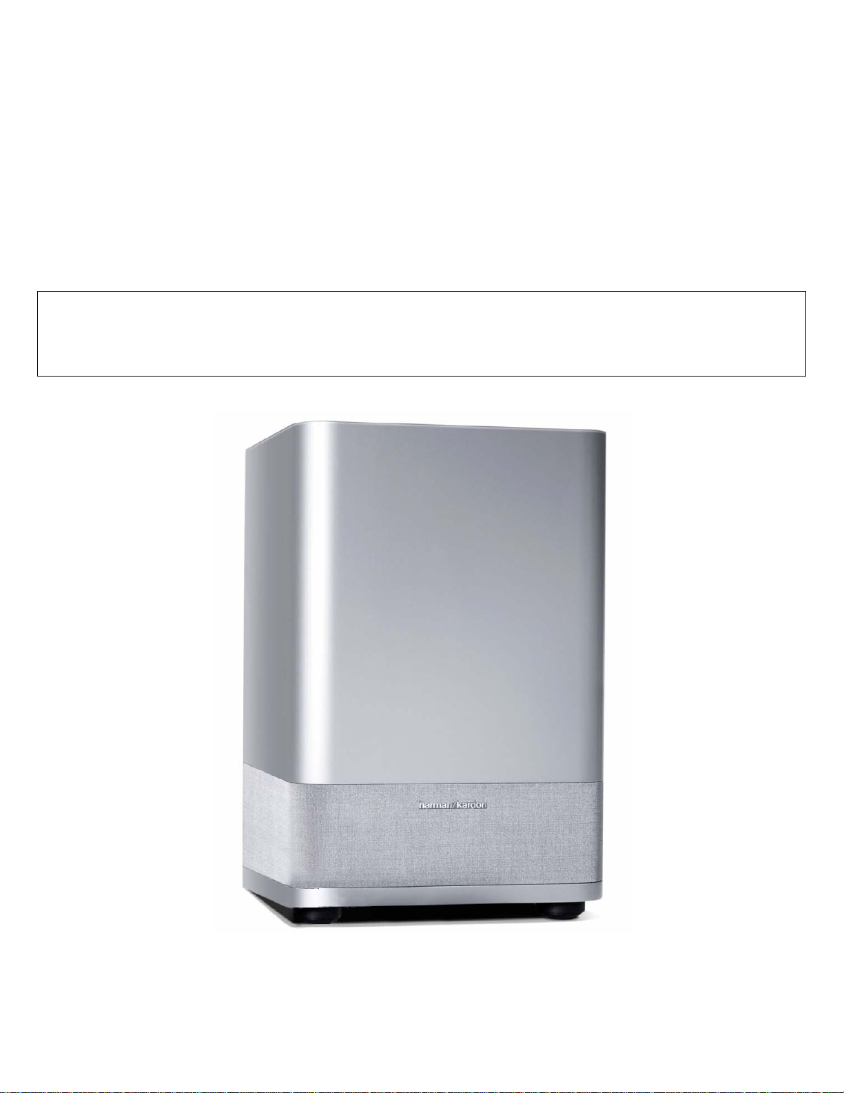
harman/kardon
SUB-TS14
(HKTS 14 SUBWOOFER)
SERVICE MANUAL
harman/kardon, Inc.
250 Crossways Park Dr.
Woodbury, New York 11797 Rev0 4/2004
Page 2

SUB-TS14
harman/kardon
CONTENTS
BASIC SPECIFICATIONS . . . . . . . . . . . . ……………………………………. . . . 1
DETAILED SPECIFICATIONS. . . . . . . . . . . . . .. . . . . . . . . ………………….. …2
CONTROLS & CONNECTIONS . . . . . . . . . . . . . .. . . . . . . . . ………………….. 4
SPEAKER CONNECTIONS……………………….………..……. . . .. . .. . . . .. . .. 6
OPERATION……. . . . . .. . . . . . . . .. .. . . . .. .. . . . . ……………………………….9
BASIC TROUBLESHOOTING GUIDE . . . . . . . . ………………………………...10
TEST PROCEDURE. . . . . . . . . . . …………………………………………………11
UNIT EXPLODED VIEW. . . . …………… ……………. .. ………... . . .. .. ... . … . 12
AMPLIFIER EXPLODED VIEW. . . . ………………... . .. ………... . . .. . . .. . .… . 13
BLOCK DIAGRAM . . . . . . . . . . . . . .. . . . . . . ……………… . . . . .. . .. . .. . . . . 14
PCB DRAWINGS. .. . . . . . . . . . . . . . .. . . . . ……… . …………. . . . .. .. .. . .. . . . 15
ELECTRICAL PARTS LIST …………. .... . .. . . . …………………………... … . . 19
SEMICONDUCTOR PINOUTS . . . .. .. .. .. . . . .. . ……………..………..………. .24
SCHEMATIC DIAGRAMS . . . . . . . . .. .. .. .. . . . .. . ………………………..……. .25
PACKAGING. . . . . . . . . . . . . .. . . . . . . ……………………… . . . . .. . .. . .. . . . . 28
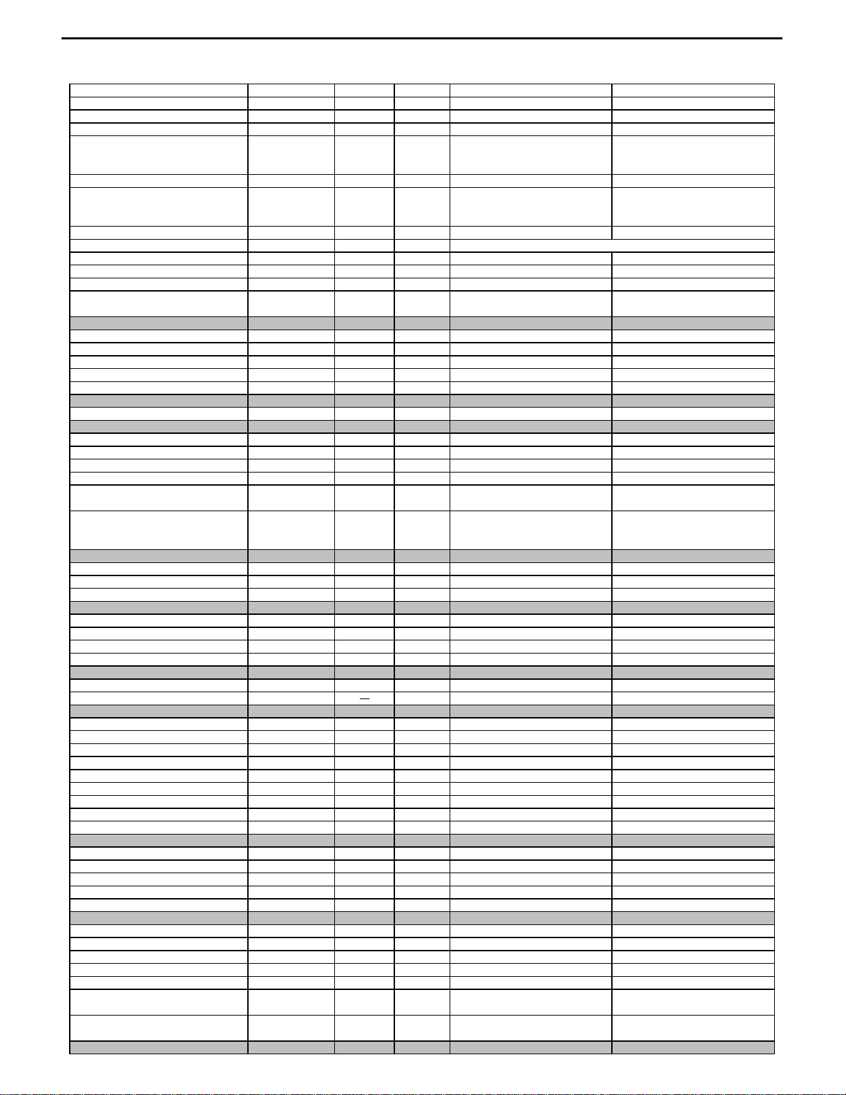
SPECIFICATIONS
Amplifier Power (RMS) 200 Watts
Driver 12" woofer, Bass Reflex Enclosure
Inputs Stereo Line Level, dedicated Subwoofer (LFE)
and Speaker Level with gold-plated binding posts
Outputs Speaker Level with gold-plated binding posts
Frequency Response 25Hz – 120Hz (Filter switch ON)
25Hz – 450Hz (Filter switch OFF)
Dimensions (H x W x D) 20-1/2" x 14-1/2" x 14-1/2"
521mm x 368mm x 368mm
Weight 48 lb/22kg
Occasional refinements may be made to existing products without notice but will always meet or exceed original specifications
unless otherwise stated.
Page 3
o
t
s
n
n
e
y
n
y
e
o
A
r
r
r
e
s
d
d
d
n
A
r
R
y
n
R
)
A
SUB-TS14
2
HKTS 14 Sub 200W Powered Sub/ Plate Amp
harman/kardon
LINE VOLTAGE Yes/N
Parameter
Amp Sectio
Type (Class AB, D, other) D n/a
Load Impedance (speaker) 3.5 Ohms
Rated Output Power 200 Watts
THD @ Rated Power 0.08 %
THD @ 1 Watt 0.15 %
DC Offset 5 mV-DC
Damping factor 16 n/a
Input Sensitivit
Input Frequency 50 Hz
Line (L&R) Input 220 mVrms
SUB (LFE) Input 125 mVrms
Speaker/Hi Level Input 3.4 Vrms
Hi Level Max. Input Voltag
Signal to Noise Rati
SNR-A-Weighted 85 dB
SNR-unweighted 62 dB
SNR rel. 1W-unweighted 64 dB
Residual Noise Floor 1.2 mVrms
Residual Noise Floor 0.8 mVrms
US 120vac/60Hz Yes 108-132 120 Vrms
Nonimal
Specification
Hi/Lo LineNom. Uni
Unit
32 Vrms
QA Test
Limits
n/a
n/a
150
0.1
0.5
20
10
n/a
154 - 308
87 - 175
2.4 - 4.8
30
82
59
59
3.0
2.0
Conditions
Nominal
50 - 250 Hz, 1 input driven, limiter off
22k filter
22k filter
@ Speaker Outputs
Measured at amplifier board
Nominal Freq.
To Rated Power
To Rated Power
To Rated Power
Nominal Freq., Min. Volume
relative to rated power
relative to rated power
relative to 1W Output
Volume @max, using RMS
reading DMM/VOM (or A/P)
Volume @max, w/ A/P Swept
Bandpass Measurement (Line
freq.+ harmonics)
Normal Operatio
Note
Notes
Bridge type amplifier, None of the
speaker terminals must be
connected to system GND at any
Measured at the speaker at speak
output terminals on the amp board.
Single input drive
SUB (LFE) input driven onl
(20 dB below Line In), Single input
-Weighting filte
22k filte
22k filte
Input Impedanc
Line Input (L, R,LFE) 10K ohms
Speaker/Hi Level Input 4.7K ohms
Filter
L&R Fixed Low-Pass Filter 160 Hz
SUB (LFE) Low pass Filter 270 Hz
Subsonic filter (HPF) 3rd Order 25 Hz
Limiter
THD at Max. Output Power
Features
Auto - On -Off Selection Switch YES
Phase Switch 0-180 deg
Filter On/Off Switch YES
Volume Pot Taper (Lin/Log) LOG
Speaker Out YES
2-Color LED power indicator YES
Power Switch YES
Fuse Holder YES
Input Configuratio
Line In (L,R)
SUB (LFE)
Speaker/Hi Level In YES
Signal Sensing (ATO
Auto-Turn-On (yes/no) YES
ATO Input test frequency 50 Hz
ATO Level Line & SUB Input 4.0 mV
ATO Level Speaker in 35 mV
ATO Turn-on time 0.9 sec.
ATO Turn-OFF Time 12 minutes
2.0 %
YES
YES
n/a
Nominal
n/a
Nominal
140 - 180
240 - 300
22 - 28
functional Refer to ATO sectio
functional
functional
functional
functional Binding post connector L&
functional Blue: On, Amber: Stand-b
functional
functional
functional Dual RCA jack
functional RCA jack
functional Binding post connector L&
functional
2.0 - 6.0
20 - 50
functional
5 - 17
@ -6dB ref. 100Hz
@ -3dB ref. 100Hz
@ -3dB ref. 30Hz
5.0
Auto - on selection switch in Auto
n/a
mp connected and AC on, then
input signal applied
Time before muting, after signal is
removed
"
"
"
3rd order fixe
2nd order fixe
3rd order fixe
Tape
Page 4
e
s
A
N
A
F
y
n
A
A
5
l
e
a
SUB-TS14
3
harman/kardon
Power on Delay tim
Transients/Pop
ATO Transient 5 mV-peak
Turn-on Transient 500 mV-peak
Turn-off Transient 500 mV-peak
Efficienc
Stand-by Input Power 8 Watts
Power Consumption @ rated power 240 Watts
Protectio
Short Circuit Protection YES
Thermal Protection YES
DC Offset Protection YES
Primary Fuse Rating
USA-Domestic 3.15 Amps
3 sec.
functional
10
700
700
12
250
functional
functional
functiona
n/a
AC Power Applied
@ Speaker Outputs
@ Speaker Outputs
@ Speaker Outputs
@ nom. line voltage
@ nom. line voltage
Direct short at output
DC present at Speaker Out leads
Type-T or Slo Blo (no DENTORI m
C Line cycled from OFF to O
C Line cycled from ON to OF
Maximum allowable input power
under nominal input voltage and
frequency, in stand-by mode (HOT
200 Watts @ 3.5 ohms and
nominal line voltage
mplifier should resume operation
after short circuit condition is
ny user accessible metal parts
should always remain at 65 degree
C or less for domestic version or 5
degree C or less for EU version.
Relay or crowbar (for driver/fir
User-replacable fuse with
UL/SEMCO rated holder.
Page 5
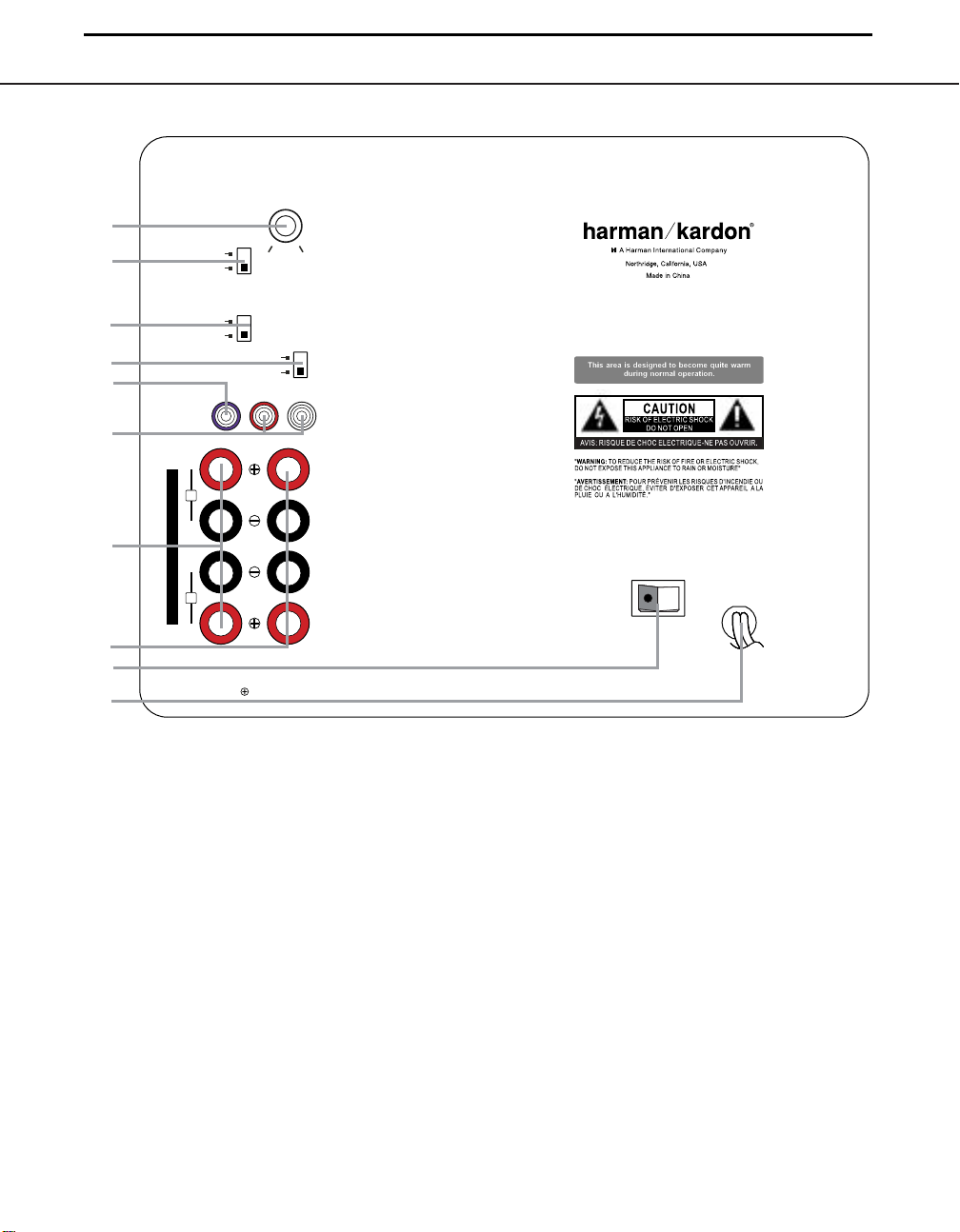
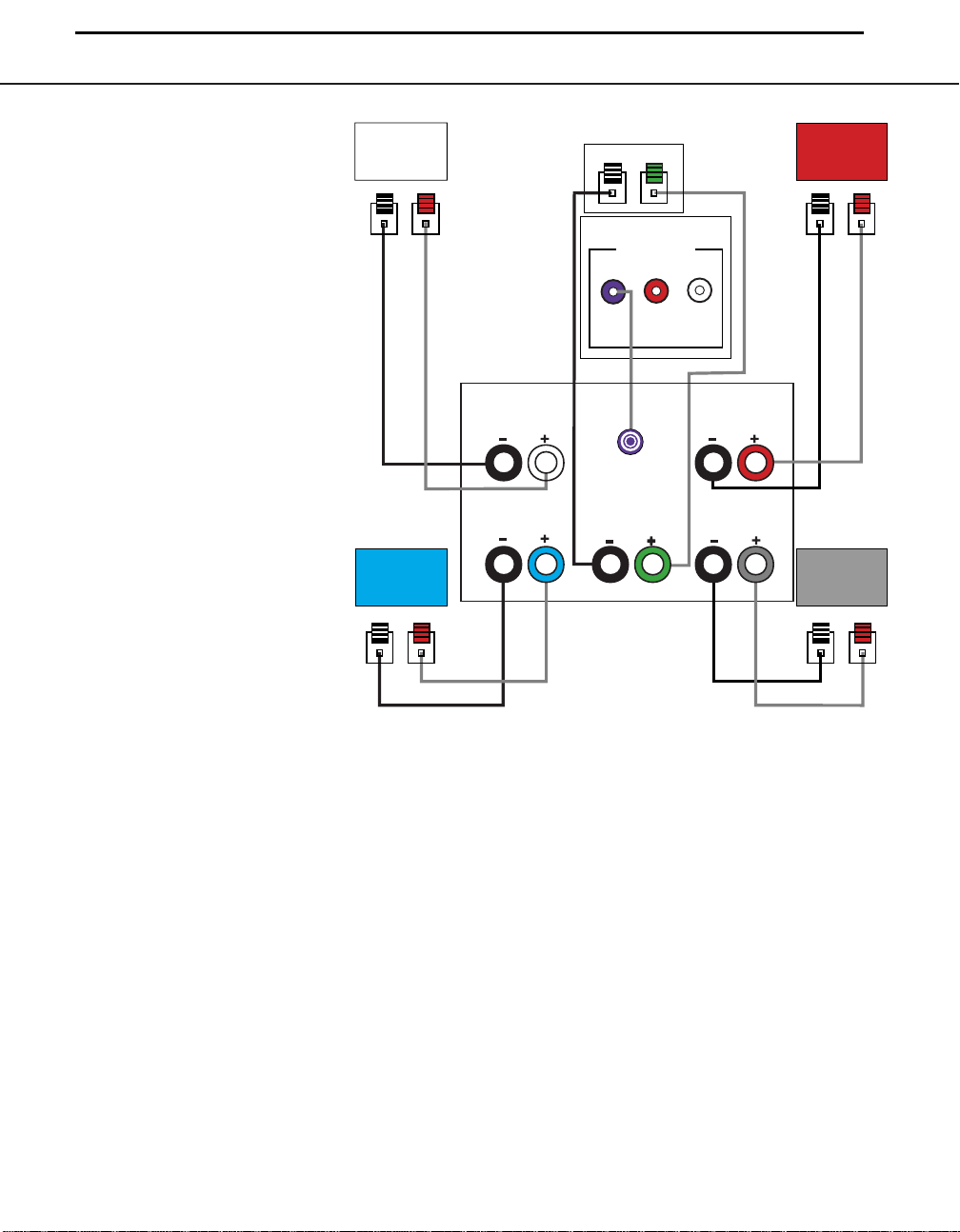
SUB-TS14 SUBWOOFER AMPLIFIER PANEL CONTROLS AND CONNECTIONS 5
SUB-TS 14 SUBWOOFER AMPLIFIER PANEL CONTROLS AND CONNECTIONS
SUB-TS14
4
harman/kardon
SUBWOOFER
¡
™
LEVEL
FILTER
ON
OFF
MAX
MIN
SUB-TS14
For use with
HKTS 14 System
£
¢
∞
§
¶
•
ª
‚
ON
AUTO
REVERSE
NORMAL
SUB
LINE
LEVEL
IN
L
H
I
G
H
L
E
V
E
L
R
IMPORTANT: CONNECT STRIPED WIRE
TO RED ( ) SPEAKER TERMINAL.
PHASE
L
R
INOUT
¡ Subwoofer-Level Control
™ High-Cut (Low-Pass) Filter Switch
£ Music-Sense On/Off Switch
¢ Phase Switch
¡ Subwoofer-Level Control:Volume
may be adjusted using the SubwooferLevel Control.Turn the control clockwise
to increase the SUB-TS14’s volume,or
counterclockwise to decrease it.
™ High-Cut (Lo w-Pass) Filter Switch:
Placing this switch in the ON position activates circuitry that cuts out all audio input
signals above 120Hz.This allows the SUBTS14 to focus its power on reproducing the
low-frequency portion of the signal, avoiding
∞ Line-Level Subwoofer (SUB) Input
§ Line-Level Full-Range Inputs
¶ Speaker-Level Outputs
• Speaker-Level Inputs
inefficiency and distortion. Engage this filter
when using the Speaker-Level Inputs •,
or when using the Line-Level Full-Range
Inputs §, unless your receiver or processor
processes its line-level output using a lowpass filter.The filter has no effect when the
SUB Input ∞ is used.
£ Music-Sense On/Off Switch: When
placed in the AUTO position, and when the
Master Power Switch ª is turned on, the
SUB-TS14 will automatically turn itself on or
CAUTION
CAUTION
RISK OF ELECTRIC SH O CK
RISK OF ELECTRIC SH O CK
RISK OF ELECTRIC SH O CK
DO NOT OPEN
DO NOT OPEN
DO NOT OPEN
POWER
AC 120V~60Hz
ª Master Power Switch
‚ AC Power Cord
place itself in the Standby mode,depending on
whether it is receiving an audio signal.When
this switch is placed in the ON position, the
SUB-TS14 will remain on,whether or not it is
receiving an audio signal.
An LED located on top of the SUB-TS14
indicates whether the SUB-TS14 is in the
ON or STANDBY state when used with the
Music-Sense On/Off Switch £ in the
AUTO position. The LED is lit blue to indicate that the SUB-TS14 is receiving an
Page 6

SUB-TS14
5
harman/kardon
SUB-TS14 SUBWOOFER AMPLIFIER PANEL CONTROLS AND CONNECTIONS
audio signal and is turned on, and the LED
is lit amber to indicate that no signal is being
received and the SUB-TS14 is in Standby
mode.
When the Music-Sense On/Off Switch £
is in the ON position, the LED will be lit
blue,whether or not an audio signal is
present.
When the Master Power Switch ª is
turned off, the LED goes dark, no matter
which position the Music-Sense On/Off
Switch £ is in.
¢ Phase Switch: This switch determines
whether the SUB-TS14 subwoofer’s pistonlike action moves in and out in phase with
the main speakers.If the speakers were to
play out of phase,the sound waves produced by the subwoofer would be cancelled
out, reducing bass response.This phenomenon depends in part on the relative placement of the speakers in the room. In most
cases,the Phase Switch ¢ should be left
in the NORMAL position. However,it
does no harm to experiment with the Phase
Switch ¢, and you may leave it in the
position that maximizes bass response.
∞ Line-Level Subwoofer (SUB) Input:
Connect the subwoofer output of a receiver
with digital surround sound decoding,such
as Dolby* Digital or DTS
input bypasses the SUB-TS14’s internal
crossover circuitry,and should only be used
®
, to this input.This
with a filtered signal. If your receiver does not
have digital decoding,you should use the
Line-Level Full-Range Inputs § instead.
§ Line-Level Full-Range Inputs: Connect
the line-level subwoofer output or preamp output(s) of your receiver or amplifier to these
inputs.If your receiver does not have a separate subwoofer output, use a Y-adaptor (not
supplied) to bridge the receiver’s preamp output to the main amp input for that channel,
and connect the long end of the adaptor
to the corresponding line-level input on the
SUB-TS14. If your receiver has only a single
subwoofer output, you may connect it to
either the left or right line-level input on the
SUB-TS14, and no Y-adaptor is needed.
¶ Speaker-Level Outputs: If you are
using the Speaker-Level Inputs • on the
SUB-TS14, you should connect these binding post terminals to your front left and right
speakers,remembering to maintain polarity
by connecting the (+) terminal on the SUBTS14 subwoofer to the (+) terminal on the
speaker, and the (–) terminal on the SUBTS14 subwoofer to the (–) terminal on the
speaker. If you are not using the Speaker-
Level Inputs •, then connect your front
left and right speakers directly to your receiver or amplifier. See pages 9 through 12 for
further information on speaker connections.
• Speaker-Level Inputs: Connect these
binding-post terminals to the main left and
right speaker terminals of your receiver or
amplifier, if your receiver or amplifier does
not have a line-level subwoofer output.
Remember to maintain polarity by connecting
the (+) terminal on the receiver/amplifier to the
(+) terminal on the SUB-TS14 subwoofer, and
the (–) terminal on the receiver/amplifier to the
(–) terminal on the SUB-TS14 subwoofer.
ª Master Power Switch: Place this
switch in the “•”position to power-on the
SUB-TS14 subwoofer.The SUB-TS14 will
then be either in the Standby mode or completely on, depending on the position of the
Music-Sense On/Off Switch £.
‚ AC Power Cord: Make sure to plug this
cord into an active,unswitched electrical outlet for proper operation of the SUB-TS14.
The cord should not be plugged into the
accessory outlets found on some audio
components.
6 SUB-TS14 SUBWOOFER AMPLIFIER PANEL CONTROLS AND CONNECTIONS
Page 7
SUB-TS14
6
SPEAKER CONNECTIONS
harman/kardon
Dolby* Digital or DTS®(or Other
Digital Surround Mode) Connection
USE THIS INSTALLATION METHOD FOR
DOLBY DIGITAL,DTS OR OTHER DIGITAL
SURROUND PROCESSORS:
Use the line-level input jack marked SUB
∞ for the Low-Frequency Effects channel.
Connect this jack to the subwoofer output
or LFE output on your receiver or amplifier.
Connect each speaker to the corresponding
speaker terminals on your receiver or
amplifier.
Make sure you’ve configured your surround
sound processor for “Subwoofer On.” The
front left, front right, center and surround
speakers should all be set to “Small.”
When all connections have been made,plug
the AC power cord on the subwoofer into
an AC outlet.
Front
Left
– +
Surround
Left
– +
Front
Left
Surround
Left
Center
– +
SUB-TS14 Subwoofer
LINE LEVEL IN
SUB
SUB/LFE
Out
Center
Receiver
L
R
Surround
Front
Right
– +
Front
Right
Right
Surround
Right
– +
Page 8
SUB-TS14
7
SPEAKER CONNECTIONS
harman/kardon
Dolby Pro Logic*
(Non-Digital) – Line Level
USE THIS INSTALLATION METHOD FOR
DOLBY PRO LOGIC APPLICATIONS (NOT
DOLBY DIGITAL,DTS OR OTHER DIGITAL
PROCESSING),WHERE THE RECEIVER/
PROCESSOR IS EQUIPPED WITH A
SUBWOOFER OUTPUT,OR A VOLUMECONTROLLED PREAMP (LINE-) LEVEL
OUTPUT:
Use the supplied RCA-type interconnect
cable to connect the
output on your receiver
the left or right Line-Level Full-Range
Input § on the SUB-TS14 subwoofer.
Use both the left and right inputs on the
subwoofer if your receiver or processor has
both left and right line-level outputs.In that
case,you will need to supply a second
interconnect cable.
If your receiver is equipped with line-level outputs but does not have a separate subwoofer
output, use a Y-adaptor (not supplied) to
bridge the receiver’s preamp output to the
main amp input for that channel, and connect
the long end of the adaptor to the corresponding line-level input on the SUB-TS14.
IMPORTANT:Do not use the SUB Input
∞ on the subwoofer with Dolby Pro Logic
processors.
If your receiver/processor has a built-in lowpass-crossover filter for the subwoofer output, you may use the SUB Input ∞ to
bypass the subwoofer’s internal crossover.
Connect each speaker to the corresponding
speaker terminals on your receiver or amplifier.
Make sure that you have configured your
surround sound processor for “Subwoofer
On.” The front left, front right, center and
surround speakers should all be set to
“Small.”
When all connections have been made,plug
the AC power cord on the subwoofer into
an AC outlet.
line-level subwoofer
or amplifier to either
Front
Left
– +
Surround
Left
– +
Front
Left
Surround
Left
Center
– +
SUB-TS14
Subwoofer
Line-Level
R
SUB/LFE
Out
Center
Receiver
Front
Right
– +
L
Front
Right
Surround
Right
Surround
Right
– +
SPEAKER CONNECTIONS 11
Page 9
12 SPEAKER CONNECTIONS
SPEAKER CONNECTIONS
Front Left
Surround Left
Center
Front Right
Surround Right
Receiver
– + – +
– +
– + – +
SUB-TS14
Subwoofer
Surround
Right
Front
Right
Surround
Left
Front
Left
Center
L
R
H
I
G
H
L
E
V
E
L
SUB-TS14
8
Dolby Pro Logic
(Non-Digital) – Speaker Level
USE THIS INSTALLATION METHOD FOR
DOLBY PRO LOGIC APPLICATIONS (NOT
DOLBY DIGITAL,DTS OR
PROCESSING),WHERE THE RECEIVER/
PROCESSOR DOES NOT HAVE A SUBWOOFER OUTPUT,OR A VOLUMECONTROLLED PREAMP (LINE-) LEVEL
OUTPUT:
Connect your receiver or amplifier’s front
left and right speaker terminals to the left
and right Speaker-Level Input • terminals on the SUB-TS14 subwoofer that are
marked “High Level In.” Connect the left and
right Speaker-Level Output ¶ terminals
on the SUB-TS14 subwoofer that are
marked “High Level Out”to the corresponding terminals on
and right speakers.
Connect your receiver or amplifier’s center,
and surround left and right speaker terminals to the corresponding terminals on the
back of your center, and surround left and
right speakers.
When all connections have been made,
plug the AC power cord on the subwoofer
into an AC outlet.
OTHER DIGITAL
the back of your front left
harman/kardon
Page 10

MIN MAX
Subwoofer
Level
MIN MAX
Subwoofer
Level
SUB-TS14
9
harman/kardon
OPERATION
Move the Master Power Switch ª
(marked Power) to the “•” (On) position.
The SUB-TS14 subwoofer will automatically
turn itself on or go into Standby mode,
depending on whether or not a signal is
being sent to it by your receiver or surround
processor, and provided that the Music-
Sense On/Off Switch £ is moved down
so that it is in the AUTO position.
When your receiver or amplifier is off, or is
not sending program material to the subwoofer, the subwoofer will be in Standby
mode and the LED Indicator on the top
of the subwoofer will turn amber.When the
sub
woofer senses an audio signal,
it will automatically turn itself on and the LED Indicator
will turn blue.If the subwoofer does not
sense a signal after
minutes,
it will automatically go into Standby
approximately twenty
mode.
When the Music-Sense On/Off Switch £
is switched to the ON position, the subwoofer will remain on, whether or not program material is playing,and the LED
Indicator will remain lit blue.
If you’ll be away from home for an extended
period of time,or if the subwoofer will not be
used, switch the Master Power Switch ª
to the OFF position.
Volume
Volume can be adjusted using the Sub-
woofer-Level Control ¡, as shown.
Turn the control knob clockwise to
increase the volume of the subwoofer,
and counterclockwise to decrease the
subwoofer’s volume.
Additional Bass Adjustments
In addition to the volume adjustments
described above,the SUB-TS14 subwoofer
includes a Phase Switch ¢ and a Filter
Switch ™ that can be used to adjust the
bass response to suit your listening environment or taste.
In most situations,the Phase Switch ¢
should be left in the NORMAL position.
If you suspect that the subwoofer is playing
out of phase with the other speakers,which
would tend to diminish bass response,try
placing this switch in the REVERSE
position.There is no harm in experimenting,
and you may return the switch to the
NORMAL position at any time. If you
rearrange your room and reposition the
speakers,it would be a good idea to check
whether they are in phase by flipping this
switch.
The High-Cut (Low-Pass) Filter Switch
™ limits the frequencies of the audio signal
inputted to the subwoofer to the low frequencies that the subwoofer reproduces
best.This allows the subwoofer to perform
more efficiently,and with superior bass
reproduction, minimizing distortion that might
occur if the subwoofer attempted to reproduce higher frequencies.This switch should
be left in the ON position, except:
1.When the SUB Input ∞ is being used,
in which case it has no effect, or
2.When the Speaker-Level Inputs • or
the Line-Level Full-Range Inputs § are
being used with a crossover or filter aboard
the receiver or processor.
In these two circumstances,place the switch
in the OFF position.
OPERATION 13
Page 11

14 TROUBLESHOOTING
TROUBLESHOOTING
SUB-TS14
10
harman/kardon
SYMPTOM SOLUTION
If there is no sound from • Check that receiver/amplifier is on and a source is playing.
any of the speakers: • Check that the powered subwoofer is plugged in and its Master Power Switch ª is switched on to the “•” position.
• Check all wires and connections between receiver/amplifier and speakers.Make sure all wires are connected.
Make sure none of the speaker wires are frayed, cut, punctured or touching other wires.
• Review proper operation of your receiver/amplifier.
If there is no sound coming • Check the “Balance” control on your receiver/amplifier.
from one speaker: • Check all wires and connections between receiver/amplifier and speakers.Make sure all wires are connected.
Make sure none of the speaker wires are frayed, cut or punctured, and that no wires are touching each other.
•
In Dolby Digital or DTS mode,make sure that the receiver/processor is configured so that the speaker in question is enabled.
• Turn off all electronics and switch the speaker in question with one of the other speakers that is working correctly.Turn
everything back on, and determine whether the problem is in the same place: i.e., the speaker that was working previously
now has no sound and the speaker that was not working now sounds fine; or whether it has moved: i.e.,the speaker that
was not working still has no sound and the speaker that was working is still fine.If the problem is in the same place, the
source of the problem is most likely with your receiver or amplifier, and you should consult the owner’s manual
for further information. If the
possible,visit our Web site at www.harmankardon.com for further information.
If there is no sound from • Check all wires and connections between receiver/amplifier and speaker.Make sure all wires are connected.
the center speaker: Make sure none of the speaker wires are frayed, cut, punctured or touching other wires.
• If your receiver/processor is set in Dolby Pro Logic mode,make sure the center speaker is not in phantom mode.
• If your receiver/processor is set in Dolby Digital or DTS mode,make sure the receiver/processor is configured so that
the center speaker is enabled.
If the system plays at low • Check all wires and connections between receiver/amplifier and speakers. Make sure all wires are connected.
volumes but shuts off as Make sure none of the speaker wires are frayed, cut, punctured or touching other wires.
volume is increased: • If more than one pair of main speakers is being used, check the minimum impedance requirements of your receiver/amplifier.
If there is low (or no) bass • Make sure the SUB ∞ or Line-Level Inputs § of the SUB-TS14 subwoofer and SUB or LFE output of your receiver
output: or amplifier are properly connected by the RCA-type interconnect cable.
• If you are using the SUB-TS14’s Speaker-Level Inputs•, check your speaker cables to make sure they are all
connected; that none of the wires are frayed, cut, punctured or touching other wires; and that you have maintained the correct
polarity by connecting positive terminals to positive terminals,and negative terminals to negative terminals.
• Make sure the subwoofer is plugged into an active electrical outlet and its Master Power Switch ª is
switched on to the “•”position.
• Check the speaker setup (bass management) settings in your A/V receiver or processor to make certain that the front,
center and surround speakers are configured for “Small,” and that the subwoofer is set for “Yes”or “On.”
If there is no sound from • Check all wires and connections between receiver/amplifier and speakers. Make sure all wires are connected. Make sure
the surround speakers: none of the speaker wires are frayed, cut, punctured or touching other wires.
• Review proper operation of your receiver/processor and its surround sound features.
• Make sure the movie or TVshow you are watching is recorded in a surround sound mode.If it is not, check to see
whether your receiver/processor has other surround modes you may use.
• In Dolby Digital or DTS mode,make sure your receiver/processor is configured so that the surround speakers are enabled.
• Review the operation of your DVD player and the jacket of your DVD to make sure that the DVD features the desired
Dolby Digital or DTS mode,and that you have properly selected that mode using both the DVD player’s menu
and the DVD disc’s menu.
problem has followed the speaker, consult your dealer for further assistance or,if that is not
for that product
Page 12

SUB-TS14
11
Test Set Up and Procedure
harman/kardon
Equipment needed:
• Function/signal generator/sweep generator
• Integrated Amplifier
• Multimeter
• Speaker cables
Initial Control Settings:
• Power Switch OFF; Filter OFF
• Level MIN (Full CCW)
• Phase, Auto/On switches do not matter
General Unit Function (UUT = Unit Under Test)
1) From the signal generator, connect one line level (RCA) cable to the Subwoofer Line Level Input jacks L/R
on the UUT. Use a Y-cable from a mono source if necessary to connect to both inputs. Do not connect to
the single, purple SUB input.
2) Turn on generator; adjust to 60mV, 50 Hz.
3) Plug in UUT; turn the power switch ON. Turn LEVEL control full clockwise (MAX)
4) LED should turn from Amber to Blue (on top of UUT); immediate and vigorous bass response should be
heard and felt from port tube opening.
5) Turn off generator, turn LEVEL control full counterclockwise (MIN), and disconnect RCA cable.
6) Connect one pair
of speaker cables to Speaker Level input terminal (IN) on UUT. Cables should be
connected to an integrated amplifier fed by the signal generator.
7) Turn on generator and adjust so that speaker level input at the amplifier is 1.2V, 50 Hz. Turn LEVEL control
full clockwise.
8) LED should turn from Amber to Blue; immediate and vigorous bass response should be heard and felt from
the port tube opening.
Sweep Function
1) Follow steps 6-8 above, using a sweep generator as a signal source.
2) Sweep generator from 20Hz to 300Hz. Listen to the cabinet and drivers for any rattles, clicks, buzzes or
any other noises. If any unusual noises are heard, remove woofers and test.
Driver Function
1) Remove woofer from cabinet; detach + and - wire clips.
2) Check DC resistance of woofer; it should be 2.8 ohms ±10%
3) Connect a pair of speaker cables to driver terminals. Cables should be connected to an integrated amplifier
fed by a signal generator. Turn on generator and adjust so that speaker level output is 5.0V.
4) Sweep generator from 20Hz to 1kHz. Listen to driver for any rubbing, buzzing, or other unusual noises.
Page 13

SUB-TS14
12
harman/kardon
Ref# Description Part Number Qty
1 Amplifier screw 352-AM04020D210 10
2 SUB-TS14 Amplifier Not for Sale 1
3 Port Tube Not for Sale 1
4 SUB-TS14 Cabinet Not for Sale 1
5 Logo 316-AG-00557 1
6 LED Not for Sale 1
7 Grille Not for Sale 1
8 Logo 316-AL-00553 1
9 12" woofer 30PF14FM-DW05 1
10 Woofer screw 352-FM04020D605 8
11 Foot Pad 320-EVA-00057 4
Page 14

SUB-TS14
13
harman/kardon
(See Mechanical Parts List on Pages 22-23)
Page 15

SUB-TS14
14
harman/kardon
Page 16

SUB-TS14
15
harman/kardon
Page 17

SUB-TS14
16
harman/kardon
Page 18

SUB-TS14
17
harman/kardon
Page 19

SUB-TS14
18
harman/kardon
Page 20

r
y
r
SUB-TS14
19
SUB-TS14 120V Electrical parts list
harman/kardon
Part numbe
Description
Reference Designato
Qt
PREAMP PCB
Resistors
110-12472j52 Resistor 4.7K 1/2W ±5% CF 52mm 2 R201,202
110-16102j26 Resistor 1K 1/6W ±5% CF 26mm 4 R213,214,215,254
110-16103j26 Resistor 10K 1/6W ±5% CF 26mm 18
110-16104j26
110-16105j26
110-16122j26
110-16134j26
110-16151j26 Resistor 150Ω 1/6W ±5% CF 26mm 1 R253
110-16154j26 Resistor 150K 1/6W ±5% CF 26mm 1 R252
110-16183j26 Resistor 18K 1/6W ±5% CF 26mm 1 R262
110-16203j26 Resistor 20K 1/6W ±5% CF 26mm 2 R237,238
110-16205j26 Resistor 2M 1/6W ±5% CF 26mm 1 R257
110-16223j26 Resistor 22K 1/6W ±5% CF 26mm 3 R247,255,256
110-16303j26 Resistor 30K 1/6W ±5% CF 26mm 2 R223,224
110-16472j26 Resistor 4.7K 1/6W ±5% CF 26mm 3 R200,207,258
110-16473j26 Resistor 47K 1/6W ±5% CF 26mm 5 R219,249,250,251,264
110-16512j26 Resistor 5.1K 1/6W ±5% CF 26mm 2 R210,211
110-16622j26 Resistor 6.2K 1/6W ± 5% CF 26mm 1 R234
110-16913j26 Resistor 91K 1/6W ± 5% CF 26mm 4 R203,204,205,206
115-h503a102 variable Resistor RV16AE-20B2-15K-A54-104(A50K) 1 VR201
Resistor 100K 1/6W ±5% CF 26mm
Resistor 1M 1/6W ±5% CF 26mm
Resistor 1.2K 1/6W ±5% CF 26mm
Resistor 130K 1/6W ±5% CF 26mm
R209,212,216,217,218,220,221,222,225,228,229,230,
232,235,240,248,260,270
3 R231,263,266
1 R259
1 R265
1 R233
Capacitors
129-a154j633 metallize capacitor 0.15U 63V ±5% MSC 2 C221,222
129-a224j633 metallize capacitor 0.22uF 63V ±5% MSC 1 C218
130-2b221k503 disc capacitor 220P 50V ±10% 12 C200,204,205,207,208,210,21,212,214,220,230,237
130-2b470k503 disc capacitor 47P 50V ±10% 1 C229
130-2f104z503 disc capacitor 0.1U 50V +80/-20% 8 C232,242,244,245,246,252,254,256
132-183j503 mylar capacitor 0.018uF 50V ±5% 1 C223
132-223ja03 mylar capacitor 0.022uF 100V ±5% 1 C215
132-473j503 mylar capacitor 0.047U 50V ±5% 1 C224
132-563j503 mylar capacitor 0.056U 50V ±5% 1 C216
132-823j503 mylar capacitor 0.082U 50V ±5% 1 C217
135-3105m50 electrolytic 1U 50V ±20% 1 C228
135-3106m50 electrolytic 10uF 50V ±20% 10 C201,202,206,213,219,231,241,243,251,253
135-3107m16 electrolytic 100uF 16V ±20% 1 C234
135-3226m50 electrolytic 22U 50V ±20% 1 C225
135-3227m16 electrolytic 220U 16V ±20% 1 C233
Semiconductors
192-027c1815gr IC 2SC1815GR NPN 3 Q201,206, 207,208
197-131n4148 diode 1N4148 26mm 11 D201,202,203,204,205,206,207,208,214,215,216
199-15000335 zener diode 3.3V 1/2W 52mm 1 D213
190-06m4558d I.C. OPA 4558D DUAL OP-AMP 1 U203
190-16tl074cn I.C TL074CN ST QUAD OP-AMP 2 U201,202
Page 21

r
y
r
SUB-TS14
20
harman/kardon
Part numbe
Description
Reference Designato
Qt
PREAMP PCB
Miscellaneous
162-50332003 2 PIN 330mm RED 1 D209
174-0rca313v RCA JACK RCA-313G V/R/W 1 JK201
174-20810360g JACK SPK JK BP 8PIN 1 JK202
175-1b08v01 wire connector 8 PIN PITCH=2.0mm 1 W202
175-1c07v01 wire connector 7 PIN PITCH=2.5mm 1 M201
180-tms7210v SWITCH SLIDE 6PIN MS7210V 3 SW201,202,203
MAIN PCB
Resistors
110-14103j26 Resistor 10K 1/4W ±5% CF 26mm 3 R503,504,510
110-14222j26 Resistor 2.2K 1/4W ±5% CF 26mm 1 R511
110-14432j26 Resistor 4.3K 1/4W ±5% CF 26mm
110-14472j26
110-16102j26
110-16103j26
110-16104j26
110-16153j26 Resistor 15K 1/6W ±5% CF 26mm 1 R107
110-16182j26 Resistor 1.8K 1/6W ±5% CF 26mm 1 R145
110-16203j26 Resistor 20K 1/6W ±5% CF 26mm 1 R309
110-16221j26 Resistor 220Ω1/6W ±5% CF 26mm 1 R144
110-16222j26 Resistor 2.2K 1/6W ±5% CF 26mm 1 R102
110-16223j26 Resistor 22K 1/6W ±5% CF 26mm 1 R316
110-16333j26 Resistor 33K 1/6W ±5% CF 26mm 1 R310
110-16393j26 Resistor 39K 1/6W ±5% CF 26mm 1 R151
110-16434j26 Resistor 430K 1/6W ±5% CF 26mm 1 R312
110-16473j26 Resistor 47K 1/6W ±5% CF 26mm 2 R106,129
110-16474j26 Resistor 470K 1/6W ±5% CF 26mm 1 R127
110-16562j26 Resistor 5.6K 1/6W ±5% CF 26mm 1 R152
110-16621j26 Resistor 620Ω1/6W ± 5% CF 26mm 1 R160
110-16751j26 Resistor 750Ω1/6W ± 5% CF 26mm 1 R315
110-16755j26 Resistor 7.5M 1/6W ± 5% CF 26mm 1 R313
116-161002f26 metal film Resistor 10K 1/6w ± 1% MF 26mm 2 R301,303
116-161202f26 metal film Resistor 12.0K 1/6w ± 1% MF 26mm 1 R302
116-162200f26 metal film Resistor 220Ω1/6w ± 1% MF 26mm 1 R317
116-162202f26 metal film Resistor 22.0K 1/6w ± 1% MF 26mm 1 R318
110-20332jk3 Resistor 3.3K 2W ±5% 7.5m 1 R134
113-50s68j00 cement Resistor 0.068Ω5w ± 5% 1 R147
116-201001jk3x metal film Resistor 1.00K 2w ± 5% MF 7.5mm 1 R148
116-304700jk2x metal film Resistor 470Ω3w ± 5% MF 10mm 2 R501,502
Resistor 4.7K 1/4W ±5% CF 26mm
Resistor 1K 1/6W ±5% CF 26mm
Resistor 10K 1/6W ±5% CF 26mm
Resistor 100K 1/6W ±5% CF 26mm
1 R506
1 R505
1 R153
10 R128,130,149,150,305,306,308,311,314,319
3 R122,126,307
Capacitors
130-2f104z503 disc capacitor 0.1U 50V ±10% 6 R107,117,122,144,320,322
130-sl101k503 disc capacitor 100P 50V SL ± 10% 3 C302,303,306
132-103j503 mylar capacitor 0.01U 50V ±5% 2 C305,317
132-103ja03 mylar capacitor 0.01uF 100V ±5% 2 C103,104
132-104ja03 mylar capacitor 0.01uF 100V ±5% 3 C123,503,504
132-273ja03 mylar capacitor 0.027uF 100V ±5% 1 C143
Page 22

r
y
r
B
SUB-TS14
21
harman/kardon
Part numbe
Description
Reference Designato
Qt
MAIN PCB
135-3106m50 electrolytic 10uF 50V ±20% 2 C319,321
135-3107m10 electrolytic 100U 10V ±20% 2 C114,115
135-3107m35 electrolytic 100U 35V ±20% 2 C507,508
135-3225m50 electrolytic 2.2U 50V ±20% 1 C509
135-3226m16 electrolytic 22U 16V ±20% 1 C304
135-3226m50 electrolytic 22U 50V ±20% 2 C505,506
135-3227m16 electrolytic 220U 16V ±20% 1 C118
135-3476m16 electrolytic 47U 16V ±20% 1 C318
132-103kb00 mylar capacitor 0.01uF 400V +/- 10% 1 C500
138-5478m80 large aluminum 4700uF 80V ± 20% 85 2 C501,502
Semiconductors
192-027c1815gr transistor 2SC1815GR 5 Q108,109,113,301,302
192-027c2235y transistor 2SC2235Y 1 Q111
192-028a1015gr transistor 2SA1015GR 3 Q101,107,112
192-1672n5551 transistor 2SN5551 2 Q114,115
192-1682n5401 transistor 2SN5401 AI-PNP 350V 500mA TO-92 1 Q503
197-013n4148 diode 100mA 75V SIGNAL 1N4148 7 Q102,103,104,105,143,301,302
199-15000625 zener diode 6.2V 1/2W 52mm 1 D101
199-15001605 zener diode 16V 1/2W 52mm 1 D502
190-16t1074cn IC TL074CN ST 1 U301
192-161tip31c transistor TIP31C SGS 1 Q501
192-162tip32c transistor TIP32C SGS 1 Q502
197-00kbu606g diode 6A 800V KBU606G 1 D501
197-101n4004 diode 1n4004 2 D110,504
Miscellaneous
109-1ttc802j0 thermister TTC-802(JS) NTC 1 TH1
120-1000003 inductor 10W AI YT-C3104-005 1CRHW 35478LTB 2 FB1,2
162-50129001 wire cable ass'y 120mm AWG28 WHT 1 W201
171-urwh124d relay RWH-SH-124D (1600 ohm) 1 RL1
175-1d02v01 wire connector 2PIN PITH=3.96mm 1 M100
175-1d03v01 wire connector 3PIN PITH=3.96mm 1 M500
CLASS D ASS'Y PC
Resistors
118-12061001j SMD Resistor 1.00K 1206 5% 4 R2,11,29,30
118-12061002j SMD Resistor 10.0K 1206 5% 3 R7,9,25
118-120610r0j SMD Resistor 10.0Ω 1206 5% 2 R22,23
118-12061201j SMD Resistor 1.20K 1206 5% 16 R31,32,33,34,35,36,37,38,39,40,41,42,43,44,45,46
118-12062002j SMD Resistor 20.0K 1206 5% 1 R26
118-12062201j SMD Resistor 2.20K 1206 5% 3 R6,13,16
118-12062701j SMD Resistor 2.70K 1206 5% 1 R10
118-12063000j SMD Resistor 300.0Ω 1206 5% 1 R24
118-12063301j SMD Resistor 3.30K 1206 5% 4 R14,15,27,28
118-12063902j SMD Resistor 39.0K 1206 5% 1 R3
118-12064700j SMD Resistor 470Ω 1206 5% 1 R8
Page 23

r
y
r
B
L
SUB-TS14
22
harman/kardon
Part numbe
Description
Reference Designato
Qt
CLASS D ASS'Y PC
118-12064701j SMD Resistor 4.70K 1206 5% 3 R1,5,12
118-12064702j SMD Resistor 47.0K 1206 5% 1 R17
118-12064704j SMD Resistor 4.70M 1206 5% 1 R4
118-120647r0j SMD Resistor 47.0Ω 1206 5% 2 R20,21
Capacitors
141-c0101k50 SMD Capacitor 100pF 50V 10% 1206 NPO 1 C4
141-c0220k50 SMD Capacitor 22pF 50V 10% 1206 SMT NPO 1 C5
141-c0561k50 SMD Capacitor 560pF 50V 10% 1206 NPO 1 C6
141-c5104m50 SMD Capacitor 1206 Y5V 0.1uF 50V ± 20% 8 C2,3,7,8,9,10,11,15
141-c7223k50 SMD Capacitor 0.022uF 50V 10% 1206 X7R 1 C13
141-d7104ka0 SMD Capacitor 0.1uF 100V 10% 1210 X7R 5 C12,14,18,19,20
141-d7104kb5 SMD Capacitor 0.1uF 250V 10% 1210 X7R 1 C1
Semiconductors
192-232irf9640 transistor FET IRF9640 IR P-CH TO-220 1 Q10
192-233irf640 transistor FET IRF640 IR N-CH TO-220 1 Q11
190-16tl072dts SMD I.C. TL072CDT SGS THOMSON 1 IC1
192-09124126qs SMD transistor 2SC2412K-T146Q/R 3 Q1,4,5
192-09139066rs SMD transistor 2SC3906K-T146R ROHM 2 Q2,8
192-09210376qs SMD transistor 2SA1037K-T146Q/R ROHM 2 Q7,9
192-09215146rs SMD transistor 2SC1514K-T146R ROHM 2 Q3,6
197-03rls4148s SMD diode RLS4148-TE11 ROHM 6 D1,2,3,4,5,6
199-15000563s SMD zener diode 5.6V 5% PHILIPS BZX84-C5V6 2 Z1,2
199-15001203s SMD zener diode 12V 5% PHILIPS BZX84-C12 2 Z5,6
199-15001503s SMD zener diode 15V 5% PHILIPS BZX84-C15 1 Z3,4
Miscellaneous
122-14121m4191 Ferrite core LS-A6206-ST EFD-30 1 L1
122-14350j4180 choke coll 35uH Ferrite Core 25 1 L2
128-e106ma01 non-polar 10uF 100V 20% 2 C16,17
175-9f40hr2 wire connector 40PIN PITCH=2.54mm HR2*40 0.2
MISCELLANEOUS/MECHANICA
150-r4055903 power transformer TT0900304490 1 T501
152-u602015 line cord SVT FT-2 6FT 1
154-k31505t0 fuse3.15A 250V 30mm UL/CSA 1 F501
155-63032i fuse holder HTB-32I 3mm UL/CSA 1 F501
162-10082007 wire RED 18AWG 80mm 8mm#1015 1
162-5050d003 wire ul11015 500mm 1 M100
162-10152001 wire ul1617 AWG22 150mm RED 1
163-11009 wire tie 100mm 2
176-Wwjcel wire Connector & Base CE-1 1
180-pbr12c11s Power switch PUSH BR12C11S 1 SW501
193-201815t2 insulator 2 for Q10,Q11,
302-AL-00373-0 Alum. Back panel
306-ABS-00004 REAR CABINET 268*213*102 A.B.S UL
311-ABS-00028 Knob 46077-W P.V.C.
Page 24

r
y
r
L
SUB-TS14
23
harman/kardon
Part numbe
Description
MISCELLANEOUS/MECHANICA
317-000-00037 Ground terminal M3 t=0.3
333-EVA-00096 EVA (gasket) 213*15*2.0mm
333-EVA-00097 EVA (gasket)213*15*1.0t
333-EVA-00121 8PIN BB EVA (gasket)
333-EVA-00132 EVA (gasket) 238*15*2.0mm
333-EVA-00133 EVA (gasket)238*15*1.0t
333-EVA-00188 EVA (gasket) 170x5x1t
333-EVA-00219 EVA (gasket)150*15*1t UL
333-EVA-00220 EVA (gasket)225*15*1t UL
333-EVA-00866 Flame less EVA (gasket) 48*18*1.5T
350-EM04012D02 4*12 screw
351-AM03008A07 SCREW M3*8
351-AM03008A07 SCREW M3*8 BLK
352-AM03008D04 3*8 B type screw
352-AM03008D04 3*8 B type screw
352-AM03010D06 3*10 P type screw
352-HM03012D08 3*12 B type Screw
353-0870122 SCREW M8*70 BLK
Reference Designato
Qt
Page 25

SUB-TS14
24
harman/kardon
Page 26

SUB-TS14
25
harman/kardon
Page 27

SUB-TS14
26
harman/kardon
Page 28

SUB-TS14
27
harman/kardon
Page 29

28
 Loading...