

Page 1
CONTENTS
ESD WARNING 2
PARTS LIST, SUB 7
harman/kardon Service Manual
SB 16/230
Active Sou ndbar with wireless subwoofer
PACKAGE GUIDE AND PARTS, CENTER 3
PACKAGE GUIDE AND PARTS, SUB 4
EXPLODED VIEW AND PARTS, CENTER 5
EXPLODED VIEW AND PARTS, SUB 6
Released EU2011 Harman Consumer Group, Inc. Rev 0, 06/2011
8500 Balboa Boulevard
Northridge, California 91329
SCHEMATIC DIAGRAMS 8
ASSEMBLY AND DISASSEMBLY, CENTER 12
OWNER’S MANUAL 16-29
Page 2
harman/kardon
SB 16/230 Service Manual
Page 2 of 29
Some semiconductor (solid state) devices can be damaged easily by static electricity. Such components commonly are called
Electrostatically Sensitive (ES) Devices. Examples of typical ES devices are integrated circuits and some field effect transistors and
semiconductor "chip" components.
The following techniques should be used to help reduce the incidence of component damage caused by static electricity.
1. Immediately before handling any semiconductor component or semiconductor-equipped assembly, drain off any electrostatic charge on
your body by touching a known earth ground. Alternatively, obtain and wear a commercially available discharging wrist strap device,
which should be removed for potential shock reasons prior to applying power to the unit under test.
2. After removing an electrical assembly equipped with ES devices, place the assembly on a conductive surface such as aluminum foil, to
prevent electrostatic charge build-up or exposure of the assembly.
3. Use only a grounded-tip soldering iron to solder or unsolder ES devices.
4. Use only an anti-static solder removal device. Some solder removal devices not classified as "anti-static" can generate electrical charges
sufficient to damage ES devices.
5. Do not use freon-propelled chemicals. These can generate electrical change sufficient to damage ES devices.
6. Do not remove a replacement ES device from its protective package until immediately before you are ready to install it. (Most replacement
ES devices are packaged with leads electrically shorted together by conductive foam, aluminum foil or comparable conductive material.)
7. Immediately before removing the protective material from the leads of a replacement ES device, touch the protective material to the
chassis or circuit assembly into which the device will be installed.
CAUTION :
8. Minimize bodily motions when handling unpackaged replacement ES devices. (Otherwise harmless motion such as the brushing together
or your clothes fabric or the lifting of your foot from a carpeted floor can generate static electricity sufficient to damage an ES devices.
Be sure no power is applied to the chassis or circuit, and observe all other safety precautions.
Each precaution in this manual should be followed during servicing.
Components identified with the IEC symbol in the parts list are special significance to safety. When replacing a component identified with
, use only the replacement parts designated, or parts with the same ratings or resistance, wattage, or voltage that are designated in the
parts list in this manual. Leakage-current or resistance measurements must be made to determine that exposed parts are acceptably
insulated from the supply circuit before retuming the product to the customer.
Page 3

harman/kardon
SB 16/230 Service Manual
Page 3 of 29
Page 4
harman/kardon
SB 16/230 Service Manual
Page 4 of 29
Page 5

harman/kardon
SB 16/230 Service Manual
Page 5 of 29
Page 6
2009/12/03
harman/kardon
SB 16/230 Service Manual
Page 6 of 29
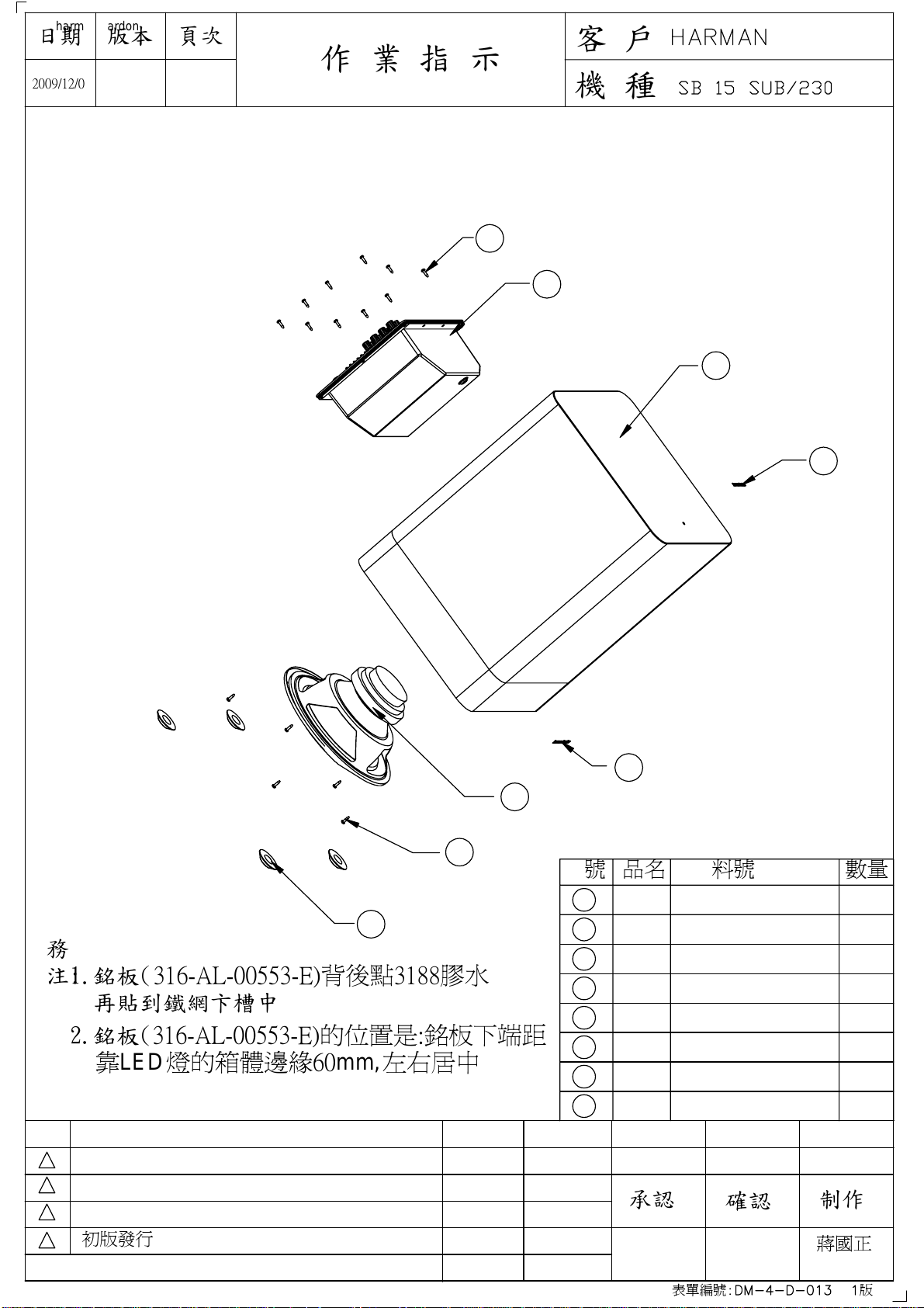
Harman/Kardon SB 16/230 subwoofer, Exploded View
版本日期
頁次
客 戶:
作 業 指 示
0
1
機 種:
1
2
3
4
5
6
7
序號 品名 料號
Screw for
1
amplifier
8
務
1.銘板(316-AL-00553-E)背後點3188膠水
注:
再貼到鐵網卞槽中
2.銘板(316-AL-00553-E)的位置是:銘板下端距
靠LED燈的箱體邊緣60mm,左右居中
3
2
1
初版發行
0
ISSUE REVISIONS
DATE NAME
Amplifier
2
Wood
3
Cabinet
Logo
4
Logo fot
5
grille
Woofer
6
Screw for
7
woofer
Rubber
8 4
Foot
承認
352-AM04020D210-E
010-7610-05246-E
241-100-00613-2BCE
316-AG-00557-E
316-AL-00553-E
25PF12DZB-FW01-E
352-FM04020D605-E
320-RUB-00057-0BAE
確認
表單編號: 版
數量
10
1
1
1
1
1
5
制作
蔣國正
2009/12/03
Page 7

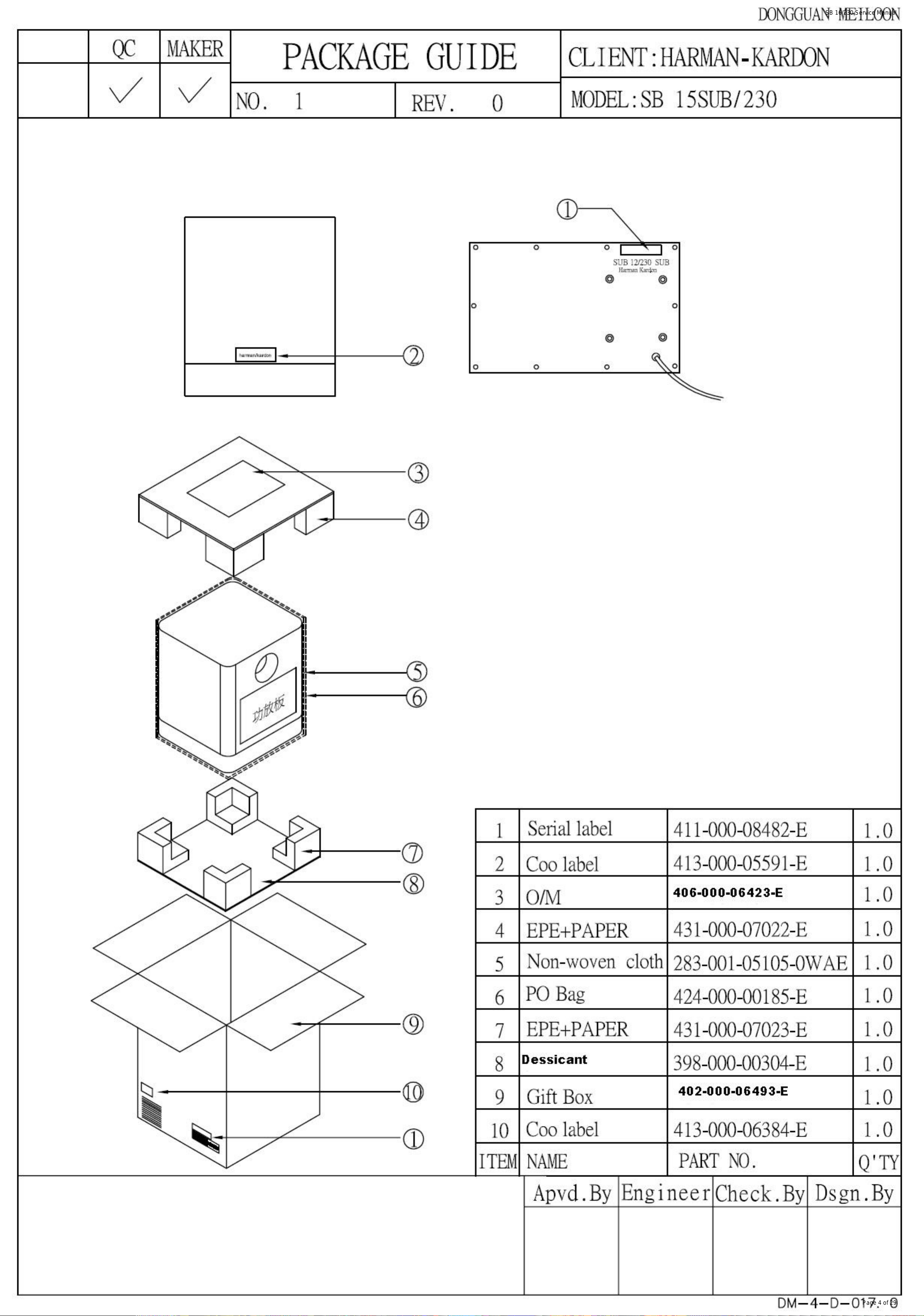
Harman/Kardon SB15 wireless subwoofer. System Parts list.
The sub is used in the SB 16/230 soundbar system.
051-A05264D-E POWER AMP PCB ASSY SB15 SUB
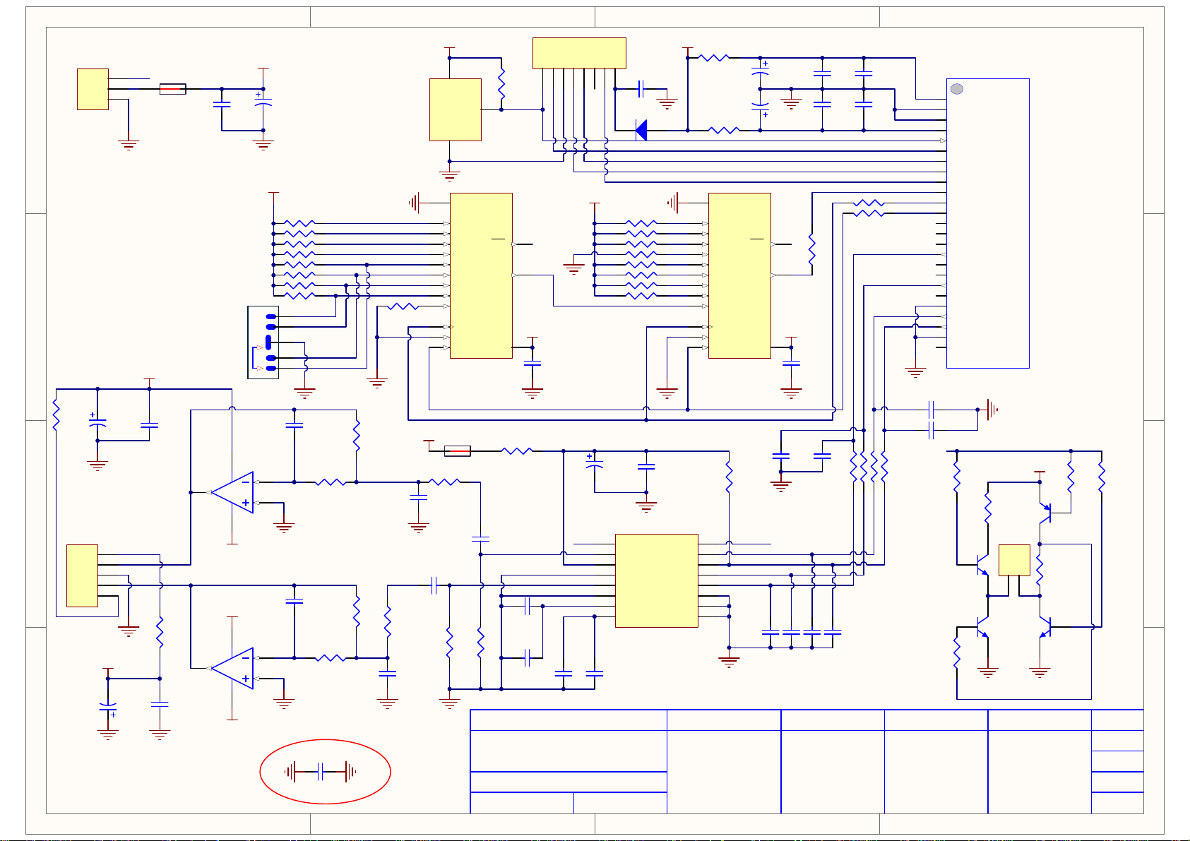
051-A05264C-E PCB WIRELESS BCB ASSY SB15 SUB
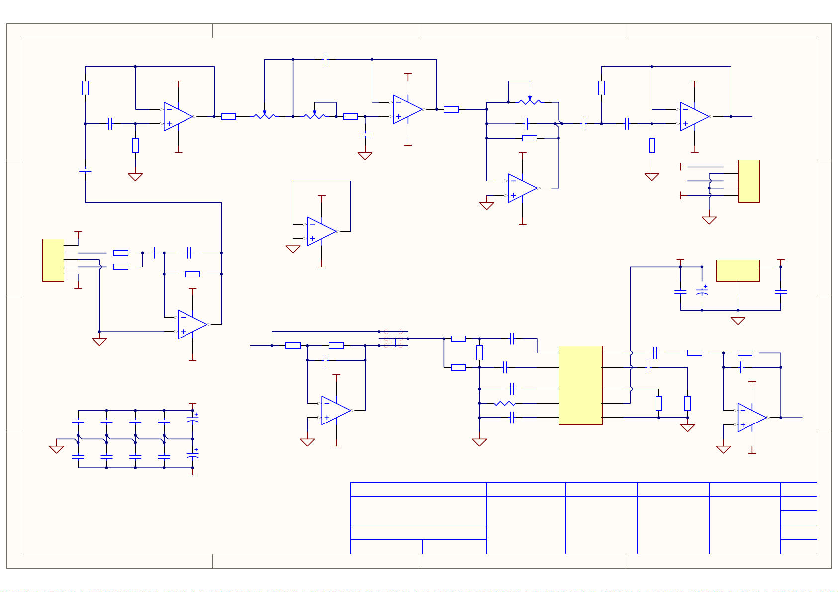
051-A05264B-E PRE AMP PCB ASSY SB15 SUB
051-A05264A-E STANDBY PCB ASSY SB15 SUB
302-FE-05275-0BAE Subwoofer Amplifier panel
150-E0764201-E Transformer
152-V60202603-E Power Cord
154-V09006T0-E Fuse
155-520020-E Fuse holder
162-50652003-E Speaker Wire
180-P3024DB-E Power Rock Switch
306-ABS-05082-0BAE Rear Enclosure
323-AL-05184-0LAE Aluminum heat sink
335-NYL-00002-0BAE Power Cord Strain Relief
311-ABS-00028-0BAE Knob
harman/kardon
SB 16/230 Service Manual
Page 7 of 29
SB15 Sub
Part Number Part Description
352-AM04020D210-E
010-7610-05246-E
241-100-00613-2BCE
316-AG-00557-E
316-AL-00553-E
25PF12DZB-FW01-E
352-FM04020D605-E
320-RUB-00057-0BAE
Screw for Subwoofer
Amplifier SB15/230 SUB
Wood Cabinet
Harman Kardon Logo for the Sub top board
Logo for grille
10" Subwoofer
Screw for woofer to wood cabinet
Rubber pad for subwoofer cabinet
Page 8
1
harman/kardon
SB 16/230 Service Manual
Page 8 of 29
2
C06
3
4
VR2A
VR*2
6
5
SGND
C05
220p
6
5
VCC
B
VSS
100n
411
U1B
TL074CD
VCC
84
2
VSS
R02
17.8k
C04
33n
SGND
7
R03
10K
7
U3B
TL072CN
MODEL:SB 15SUB/230
R12
VCC
VSS
12.1K
C23
4.7u
C34
4.7u
C30
100n
C09
100n
SGND
R01
22K
R08
22K
C22
4.7u
C37
4.7u
SGND
R16
82.5k
C26
4.7u
C36
4.7u
A A
B B
C C
D D
CON1
5
4
3
2
1
Header 5
SGND
VCC
411
13
D
12
U1D
TL074CD
VSS
C01
10u
VCC
411
2
A
3
VSS
VCC
C25
100n
C35
100n
VSS
14
C02
220P
U1A
TL074CD
C21
100u
C32
100u
R04
15.4k
VR2B
VR*2
SGND
R06
18.7k
1
mout
R10
10K
VCC
411
3
1
2
9
10
sw1
SW2-2
C
VSS
6
4
5
8
U1C
TL074CD
Netsw1_3
R05
24.9K
CUSTOMER:JBL
R17
6.8k
R07
10k
R21
8.25k
SGND
SGND
R18
3.3k
C38
220n
C12
100n
C17
10u
R22
22k
2
3
VCC
VSS
+12VC
OUT
R19
24.9k
SGND
VCC
8
1
4
VSS
R23
47k
1
U2A
TL072CN
SGND
U5
MC78L12CP
1
C11
100u
R20
14.3k
OUT
mout
CON2
Header 5
GND
2
SGND
C29
220p
2
3
1
2
3
4
5
IN
VCC
1
VSSSGND
8
U3A
4
TL072CN
VCC
3
C13
100n
1
OUT
OUTa
SW
GND
V+
R11
12.1K
9
2
7
1
10
C15
100n
SGND
C28
4.7u
R15
82.5k
VR1
A50k
C03
100p
VCC
R09
220k
84
6
5
C16
10u
2
VSS
C18
220n
C27
22n
7
U2B
TL072CN
U4
INb8OUTb
3
INa
4
INT
6
SENCE
5
Vref
NJM2761-10
C08
100n
PREPAREDCHECKEDCHECKEDAPPROVED REV
1.0
BOARD: PERAMP
DETA:SEP.01.2009
PAGE 2/5
1
2
3
4
Page 9
1
harman/kardon
SB 16/230 Service Manual
Page 9 of 29
C14
100n
8
4
VSS
VCC1
84
VSS
VCC
GND
VCC
SW1
SEL
U05A
NJM4560
2
3
U05B
NJM4560
6
5
GND
C13
470u/16V
20KR07
20KR09
20KR11
20KR14
20KR16
20KR18
20KR20
20KR22
5
4
3
2
1
GND
AGND
AGND
C19
150p
C27
150p
R35
3.9k
C22
0.22u
R41
3.9k
GND GND
R24
10K
GND
R27
20k
C23
1n
AGND
R39
R40
20k
10k
C31
1n
AGND
AGND
CON2
A A
B B
C C
D D
R25
33R
CON3
Header 5
Header 3
AGND
1
2
3
4
5
link1
GND
VCC1
C33
470u/16V
BD1
BD
C17
100n
3
2
1
C18
470u/16V
AGND
VSS
AGND AGND
R37
33R
C24
100n
12
1
7
8
6
5
4
3
14
13
12
11
10
2
15
1
VCC
1 2
C26
10u
R42
10k
AGND
2
VCC
3
Vcc
nRESET
Vss
1
GND
GND
H
G
F
E
D
C
B
A
SI
CLK
CLK INH
S/L
SN74HC165D
BD2
BD
R28
10k
R43
10k
CON1
Header 8
1234567
R03
47k
rest
2
U02
STM809
R08
R10
U03
R12
R15
7
QH
QH
VCC
C25
10u
R36
33R
R17
R19
R21
9
R23
GND
VCC
16
C15
100n
GND GND
link1
C28
C32
100n
10u
C29
100n
VCC
C20
1000u/10V
16
15
14
13
12
11
10
9
C30
10u
8
C01
100n
D01
SCD14
20K
20K
20K
10K
20K
20K
20K
20K
AGND
U06
MUTEC
AOUTL
AV
AGND
AOUTR
REF_GND
VQ
FILT+
CS4340
GND
GND
C21
100n
SDATA
SCLK/DEM1
MCLK
VCC
/RST
LRCK
DIF1
DIF0
DEM0
R01
4.7R
1000u/10V
R04
4.7R
8
6
5
4
3
14
13
12
11
10
2
15
1
SN74HC165D
1
2
3
4
5
6
7
8
GND
H
G
F
E
D
C
B
A
SI
CLK INH
S/L
AGND
CUSTOMER:JBL
MODEL:SB 15SUB/230
BOARD: WIRLESS
C07
CLK
3
R33
4.7K
QH
QH
VCC
rest
C34
open
C02
1000u/10V
GND
U04
7
9
VCC
16
C39
open
GND
C35
open
C36
open
R13
100R
C16
100n
R29
100R
C37
open
C03
100n
C05
100n
C38
open
R30
100R
R45
100R
R44
100R
C04
10n
C06
10n
R31
100R
GND
R32
100R
10
11
12
13
14
15
16
17
18
19
20
21
22
23
24
25
1
2
3
4
5
6
7
8
9
C40
open
C41
open
R52
47k
MD1
RX M1087
RFVcc
RFGND
GND
Vcc
/RST
PB1(CS0)
MSIO0
MOSI0
SCK0
PF0(ID_DATA)
PF1(ID_CLK)
PC0(ID_LATCH)
/PC1(MUTE_LED)
/PC4(BOND_LED)
PC5
MCLK
PC7(I2C_SDA)
PI0(I2C_SCL)
LRCK
PI2
AGND1
SDOUT
SCK
AGND2
AVdd
Rx M1087
link1
R49
20k
R48
510
CON4
Q02
8050S
Header 2
Q03
8050S
PREPAREDCHECKEDCHECKEDAPPROVED REV
GND
4
Q04
8550S
R47
510
Q01
8050S
R50
47k
VCC
1
2
GNDGND
DETA:SEP.01.2009
PAGE 3/5
1
2
3
4
R51
47k
1.0
Page 10

1
harman/kardon
SB 16/230 Service Manual
Page 10 of 29
2
3
4
5
6
7
8
VDDA2 VSSA2 VDDP VSSP
VSSA2
R06
C16
30.1K
100n
9
8
11
2
4
5
C50
100n
C57
100n
BD1
BD
U1
IN1-
IN1+
SGND1
SGND2
IN2-
IN2+
VDDA2 VSSA2
VDDP
12
10
VDDA1
VDDA2
3
C05
100n
C02
470u
12
VSSA1
VSSA2
1
R01
10R
7
OSC
TDA892XBTH
PROT13N.C.
C53
220p
VSSD24STABI
19
VDDA2 VSSA2
CUSTOMER:JBL
MODEL:SB 15SUB/230
C15
100n
C19
100n
C52
100n
C58
100n
16
15
22
21
12
VDDP VSSP
C14
470p
R07
10R
C27
15n
C39
15n
R19
10R
VDDP VSSP
VSSP
C07
100n
120n/63V
120n/63V
C59
470p
C13
470p
L01
33uH
C28
L02
33uH
C45
C08
470u/35v
C60
470p
R02
10R
BD4
BD
C29
470n/63V
C32
330p
BD6
BD
C49
470n/63V
C46
330p
SUBOUT+
12
R13
22R
C33
100n
SUBOUT-
12
22R
R17
C55
100n
2R2
R24
C63
330p
2R2
R23
C64
330p
C62
6.8n
C61
6.8n
CON3
1
2
CON2
C11
47u/100v
C18
MODE
6
MODE
18
C56
100n
VSS
14
VDDP1
VDDP2
23
VDDP VSSPVSSP
C03
470u/35v
100n
C51
100n
17
20
C06
100n
VSSP1
VSSP2
OUT1
BOOT1
BOOT2
OUT2
BD2
BD
PREPAREDCHECKEDCHECKEDAPPROVED REV
1.0
SGND
SUB
C31
100n
C54
100n
VSS
CON2
1
2
3
4
5
Header 5
R10
5.6k
C23
1n
VCC
+15v
-15v
R14
5.6k
VCC
C20
1u
C26
1u
R21
0R
C01
470u/35v
C12
100n
C17
100n
C25
1n
SGND
C04
100n
CON1
std
C10
2.2u
C42
22n
C65
2.2n
C66
2.2n
C38
22n
Header 6
R05
30.1k
1
2
3
4
5
6
D02
1N4148
C24
6800u/35v
C34
100n
BR1
Bridge1
C43
6800u/35v
Q06
8550S
C21
100n
C48
100n
VCC
R11
4.7K
R20
4.7K
R03
24k
DZ1
5.6V
R08
100/2W
R12
680R
C36
22u/35v
C40
22u/35v
R18
680R
R22
100/2W
C09
220u/25V
C35
100n
C41
100n
Q02
D882
Q04
B772
MODE
A A
+3.6V
R04
10K
B B
D01
1N4148
C C
CON4
3
3
2
2
1
1
D D
DZ2
C22
1n
Q03
8050S
SUB
+15v
-15v
R09
15K
R15
1.3K
R16
15K
220u/25v
C44
220u/25v
-15v
VCC
+15v
C30
VSS
BOARD: POWER AMP
DETA:SEP.01.2009
PAGE 4/5
1
2
3
4
5
6
7
8
Page 11

1
harman/kardon
SB 16/230 Service Manual
Page 11 of 29
2
3
4
Q01
8050S
R16
0R
C01
15uf/400V
C12
0.1u/25V
C13
47uF/16V
R15
0R
GND
R05
100K
R18
0R
D07
SF16
Q03
8050S
GND
R23
100k
HI VOL
R03
1.1meg
R04
1.1meg
1
2
3
C15
680P
R10
100k
ICSP
U02
OB
VCC
GND
CT4FB
THX203H
D01
+12VB
1N4007
D03
1N4007
D04
1N4007
D06
1N4007
R13
4.7k
A A
L02
8mH
1 2
GND
N_IN
2
CON2
Header 2B
3 4
C19
1000p
L_IN
1
C16
10n
2
CON3
Header 2B
L_OUT
1
K1
Relay-SPST
Q02
8050S
GND
D08
1N4148
R20
B B
C C
open
R22
open
C07
0.22u
RV1
14D471K
C20
1000p
R02
R01
300k
300k
D05
UF1010
8
OC
7
OC
6
IS
5
C18
R11
22n
2R
std
HI OPERATIVE
LOW OPERATIVE
C08
470PF/1k
R12
2R
GND
TR1
1
W1
2
W2
3
4
W3
5
S1
S2
TRANSFORMER
op1
PC817C
std
+3.6V
C03
330pF
CON1
Header 3
1
2
3
TR
4
3
R21
0R
OPEN:R05,Q01,R13,R18
OPEN:R15,R16
W4
GND
R07
510
D09
UF302
8
6
7
D02
UF302
6
1
2
2 1
GND
C06
100u/25V
+3.6VA
R06
10k
C17
0.1u
3
U01
ST TL431
+12VA
C04
470u/16V
R09
10k
C09
0.1u
C10
0.1u
L1
Inductor
22uH
R19
68 ohm
C05
470u/16V
R08
4.42K
R14
10k
GND
+3.6V
C11
0.1u
+12VB
+3.6VA
AK
GND
R17
680R
GND
LED1
CUSTOMER:JBL
D D
MODEL:SB 15SUB/230
PREPAREDCHECKEDCHECKEDAPPROVED REV
1.0
BOARD: STANDBY POWER
DETA:SEP.01.2009
PAGE 5/5
1
2
3
4
Page 12

Because the design itself, once disassembling the system, the top bottom trim panels snap points will break and new trim panel has to be replaced
1 Check the cabinet Check the baffle Attach protective film on the rear cabinet
harman/kardon
SB 16/230 Service Manual
Page 12 of 29
ASSEMBLY AND DISASSEMBLY, SB 16 SOUNDBAR.
2 Attach EVA foam gasket attach EVA foam gasket
3 load woofer ( screw PN 352-AM 04008C1334-E X 16 pcs )
4 load tweeter add adhesives attach tweeter bar and screw down screw pn 352- AM03008C1086-E
5 left chan Xover (P/N 013-7600-05766-E) r ight chan xover (P/N 013-7600-05766-1E) Screw PN 352-AM03008C1086-E
Page 13

black/red cables on crossovers to be
harman/kardon
SB 16/230 Service Manual
Page 13 of 29
pulled inward the amplifier
6 Plug green/black cables to the woofer, green cable for + polarity, and black for - polarity plug blue cable to tweeter +, and black to tweeter -
7 Apply adhesives Assemble knobs/LEDs Screw PN 352-AM03008C1086-E X 1 pcs
8 Assemble Amp Screw down amp ( Screw X 9 pcs PN: 352-AM03008C1086-E )
Page 14

圖1
harman/kardon
SB 16/230 Service Manual
Page 14 of 29
9 load in insulation X 2 pcs
10 plug in xover harness to the amp plug in button.key harness left channel crossover right channel crossover
11 attach baffle to rear enclosure scrw PN 352-AM03510D112-E X 20 pcs
Page 15

12 apply adhesives press in the grille
harman/kardon
SB 16/230 Service Manual
Page 15 of 29
13 Snap in the top gloss trim panel snap in the bottom gloss trim panel
14 attach the side end cap ( peel off adhesive ) and add super glue attach the end cap to the cabinet
Page 16

SB 16/230
harman/kardon
SB 16/230 Service Manual
Page 16 of 29
Active speaker soundbar
Owner’s Manual
Page 17

SB 16/230
harman/kardon
SB 16/230 Service Manual
Page 17 of 29
Table of Contents
INTRODUCTION 3
DESCRIPTION AND FEATURES 3
INCLUDED ITEMS 3
SOUNDBAR TOP-PANEL CONTROLS 4
SOUNDBAR REAR-PANEL CONTROLS AND CONNECTIONS 4
SUBWOOFER REAR-PANEL CONTROLS 5
SPEAKER PLACEMENT 6
PLACING THE SOUNDBAR ON A TABLE 6
WALL-MOUNTING THE SOUNDBAR 6
PLACING THE SUBWOOFER 6
CONNECTIONS 7
SOURCE CONNECTIONS 7
POWER CONNECTIONS 8
OPERATION 9
TURNING THE SOUNDBAR ON AND OFF 9
TURNING THE SUBWOOFER ON AND OFF 9
ADJUSTING THE SYSTEM’S VOLUME 9
MUTING THE SYSTEM 9
SOUNDBAR SURROUND MODE BUTTON 9
SOUNDBAR SRC (SOURCE) BUTTON 9
SUBWOOFER VOLUME KNOB 10
SOUNDBAR TRIM SWITCH 10
WIRELESS CODE SWITCHES 10
SUBWOOFER CROSSOVER KNOB 10
SUBWOOFER PHASE SWITCH 10
2
PROGRAMMING THE SOUNDBAR TO RESPOND TO YOUR TV REMOTE 11
TROUBLESHOOTING 12
SPECIFICATIONS 13
Page 18

SB 16/230
harman/kardon
SB 16/230 Service Manual
Page 18 of 29
Introduction, Description and Features, Included Items
ENGLISH
Introduction
Please register your product on our Web site at
www.harmankardon.com.
Note: You’ll need the product’s serial number.
At the same time, you can choose to be
notified about our new products and/or special
promotions.
Thank you for purchasing the harman kardon® SB 16/230 speaker system, with which
you’re about to begin many years of listening enjoyment. The SB 16/230 has been
custom-designed to provide the excitement and power of the cinema experience in your
own living room.
While sophisticated electronics and state-of-the-art speaker components are hard at work
within the SB 16/230, hookup and operation are simple.
To obtain maximum enjoyment from your new soundbar speaker system, we urge you to
take a few minutes to read through this manual. This will help ensure that the connections
you make are correct. In addition, a few minutes spent learning the functions of the various
controls will enable you to take advantage of all the power and refinement the SB 16/230
is able to deliver.
If you have any questions about this product, its installation or its operation, please contact your retailer or custom installer, or visit our Web site at www.harmankardon.com.
Description and Features
The SB 16/230 is a complete home theater speaker system that includes:
A video-shielded stereo soundbar speaker (the • SB 16 CTR) with two-way dual-
driver left and right speakers and built-in 25-watt x 2 stereo amplifier
A 10-inch (250mm), 100-watt wireless powered subwoofer (the • SB 15/230 SUB)
Wall-mount brackets for the soundbar •
A 6.5-foot (2m) stereo audio cable for connecting the system directly to your TV’s •
audio output.
The SB 16 CTR soundbar contains the system’s left and right speakers and stereo amplifiers,
and features digital signal processing with virtual 3D surround circuitry that creates a
complete surround-sound experience without any extra speakers or wires. You can set the
soundbar on a table in front of your TV; also, the system includes hardware that makes it
easy to mount the soundbar on the wall along with your flat-panel TV. You can program the
soundbar to respond to your TV remote’s volume, power and source commands.
The SB 15/230 SUB subwoofer receives its signal from the SB 16 CTR soundbar via wireless
technology, so you can place it anywhere in your room without having to run any wires.
Its 10-inch (250mm) woofer and built-in 100-watt amplifier deliver a movie’s impact and
excitement. Other conveniences include a volume control, a phase switch for fine-tuning
bass performance to suit your listening environment, and an efficient switching system that
senses the presence of an audio signal and automatically switches the subwoofer on.
harman kardon invented the high-fidelity receiver more than 50 years ago. With state-ofthe-art features and time-honored circuit designs, the SB 16/230 system will turn your
flat-screen TV into a fun and exciting home theater.
Included Items
One SB 16 CTR soundbar speaker
One SB 15/230 SUB 10-inch (250mm) 100-watt wireless subwoofer
Two sets of wall-mount brackets for the soundbar – one shallow and one extended (for
when the optical digital audio input is being used)
Two rubber feet
One 1.5m (5-ft) optical digital audio cable
One 2m (6.5-ft) stereo audio cable
One 24V DC power supply and one AC power
cord for the SB 16CTR speaker
Important: If anything is missing, or if any part of your SB 16/230 system fails to operate
properly, contact your dealer immediately.
3
Page 19

SB 16/230
harman/kardon
SB 16/230 Service Manual
Page 19 of 29
Soundbar Top-Panel Controls and
Soundbar Rear-Panel Controls and Connections
Soundbar Top-Panel Controls
Power
Button
Power
Indicator
Power Button: When the soundbar is in the Standby mode (the Power Indicator is amber),
press this button to turn the SB 16/230 system on (the Power Indicator turns blue.) NOTE:
When the soundbar is in the Standby mode, it will automatically turn on whenever it detects
an audio signal at the Source 1 (analog) inputs.
When the SB 16/230 system is on:
• Momentarily press the Power button to mute the SB 16/230 system. (The Power Indicator
flashes blue.)
• Hold down the Power button for three seconds to put the soundbar in the Standby
mode. (The Power Indicator turns amber.) NOTE: The subwoofer will remain on for
approximately 15 minutes after the audio signal ceases and then will automatically go
into the Standby mode.
Surround Mode Button: This button turns the SB 16/230 system’s 3D Surround processing
On and Off. The Surround Mode Indicator turns blue when 3D Surround is active and turns
white when 3D Surround is not active (normal stereo sound). See Soundbar Surround Mode
Button, on page 9, for more information.
Volume Up/Down Buttons: Press the ( – ) button to reduce the volume; press the ( + )
button to increase the volume.
Source Selector Button: This button switches between the sources connected to the Source
1 (analog) and Source 2 (digital) inputs. When Source 1 is active, the Source Indicator turns
white; when Source 2 is active, the Source Indicator turns blue.
Surround
Mode
Button
Surround
Mode
Indicator
Volume
Up/Down
Buttons
Source
Selector
Button
Source
Indicator
Soundbar Rear-Panel Controls and Connections
Wireless Code Switch: Selects between four different channels for the wireless subwoofer
signal.
IMPORTANT: Be sure to set the subwoofer’s Wireless Code switch to the same channel
that you set the soundbar’s Wireless Code switch. See Wireless Code Switches, on
page 10, for more information.
EQ Switch: This switch adjusts the soundbar’s bass for either wall or table mounting.
If you’re mounting the soundbar on a wall with the included wall-mount brackets, set
this switch to the Wall position for the most natural-sounding bass performance. If you
are placing the soundbar on a table, set the EQ switch to the Table position for the most
natural-sounding bass performance.
Trim Switch: This switch adjusts the soundbar’s input sensitivity so it will work with TVs
that have different audio signal output levels. See Soundbar Trim Switch, on page 10, for
more information.
Source 1 Connection (analog): Use the included stereo audio cable to connect the stereo
analog outputs of your TV, DVD player or cable/satellite tuner here.
Source 2 Connection (digital): If your TV, DVD player or cable/satellite tuner has a coaxial
digital output, you can connect it here.
NOTE: If you connect your TV or another component to the soundbar’s Source 1 connection,
you can connect a different component to the Source 2 connection.
Power Connection: Connect the included DC power supply here. See Power Connections,
on page 8, for more information.
IMPORTANT: Do not connect the power supply’s AC cord to an AC outlet until you
have made and verified all connections.
Power Switch: Set this switch to the On position (press the switch’s white dot) to activate
the soundbar. In normal operation, this switch will be left in the On position. See Turning
the Soundbar On and Off, on page 9, for more information.
4
Wireless Code
Switch
EQ Switch Trim Switch
Source 1
(Analog)
Input
Source 2
(Coaxial Digital)
Input
Source 2
(Optical Digital)
Input
Power
Switch
Power
Input
Page 20

SB 16/230
harman/kardon
SB 16/230 Service Manual
Page 20 of 29
Subwoofer Rear-Panel Controls
Crossover
Knob
Volume
Knob
Phase
Switch
Subwoofer Rear-Panel Connections
ENGLISH
Wireless
Code
Switch
Crossover Knob: This knob adjusts the subwoofer’s crossover between 50Hz and 150Hz.
The higher you set the Crossover knob, the higher in frequency the subwoofer will operate
and the more its bass will “overlap” that of the soundbar. This adjustment helps achieve
a smooth transition of bass frequencies between the subwoofer and the soundbar for a
variety of different rooms and subwoofer locations. See Subwoofer Crossover Knob, on
page 10, for more information.
Volume Knob: Use this control to balance the subwoofer’s volume with that of the soundbar.
Turn the knob clockwise to increase the subwoofer’s volume; turn it counterclockwise to
decrease the subwoofer’s volume.
Phase Switch: This switch determines whether the subwoofer driver’s piston-like action
moves in and out in phase with the speakers in the soundbar. If the subwoofer were to
play out of phase with the soundbar speakers, the sound waves from the soundbar could
cancel out some of the sound waves from the subwoofers, reducing bass performance
and sonic impact. This phenomenon depends in part on the placement of the subwoofer
and soundbar relative to each other in the room. See Subwoofer Phase Switch, on
page 10, for more information.
Wireless Code Switch: Selects between four different channels for the wireless subwoofer
signal.
IMPORTANT: Be sure to set the soundbar’s Wireless Code switch to the same channel
as you set the subwoofer’s Wireless Code switch. See Wireless Code Switches, on
page 10, for more information.
AC
Fuse
Power
Cord
Power
Switch
AC Fuse: The SB 15/230 SUB is factory-equipped with a T1AL/250V 1A – 250V AC fuse.
If the fuse ever blows:
1. Unplug the power cord from the wall.
2. Use a screwdriver to remove the blown fuse.
3. Replace the fuse with an identical T1AL/250V 1A – 250V AC fuse.
CAUTION: FOR CONTINUED PROTECTION AGAINST FIRE, REPLACE THE FUSE ONLY
WITH THE SAME TYPE AND RATING.
Power Cord: Plug this cord into an active, unswitched AC outlet. See Power Connections,
on page 8, for more information.
Power Switch: Set this switch to the On position to activate the subwoofer. In normal
operation, this switch will be left in the On position. See Turning the Subwoofer On and
Off, on page 9, for more information.
Status Indicator (on top of unit, not shown): Turns blue when the subwoofer’s power
switch is in the On position; turns amber when the subwoofer is in Standby; turns off when
the subwoofer’s Power switch is in the Off position.
5
Page 21

SB 16/230
harman/kardon
SB 16/230 Service Manual
Page 21 of 29
Speaker Placement
Speaker Placement
Placing the Soundbar on a Table
If your TV is placed on a table, you can place the soundbar on the table directly in front of
the TV stand, centered with the TV screen. Attach the supplied rubber feet to the soundbar
as shown in the illustration.
As long as the table’s surface is flat, the soundbar will rest on the rubber feet.
Wall-Mounting the Soundbar
If your TV is attached to a wall, you can use the included wall-mount brackets to mount
the soundbar on the wall directly below the TV screen.
1. Determine the location for the soundbar on the wall. Make sure that the top of the
soundbar will not block your view of the TV screen when it is mounted on the wall.
2. Mark the locations of the soundbar wall-mount bracket holes on the wall. The holes
for the left and right brackets are spaced 600mm apart and are designed to accept
#8 screws. The top and bottom holes for each bracket are spaced 25mm apart. See
the illustration below.
25mm
600mm
NOTE: To ensure that the soundbar will be level, use a carpenter’s level, laser sight or other
device to ensure that the two sets of holes are at exactly the same height.
3. If you are using the soundbar's optical digital audio input, select the extended wall-mount
brackets. Otherwise, select the shallow wall-mount brackets.
4. Attach the two wall-mount brackets to the wall at the locations you marked, using
hardware that is appropriate for the wall’s construction and materials. Note that the
soundbar weighs 3.6kg (8 lb). Be sure to use hardware that can support this weight.
5. After making all of the connections described in the Connections section, on page 7,
attach the soundbar to the brackets by sliding the slots in its feet onto the brackets’
vertical tabs.
Slide Slots in Soundbar Feet
onto Tabs on Brackets
Placing the Subwoofer
Since our ears do not hear directional sound at the low frequencies where the subwoofer
operates, it will perform well from just about any location in your room. However, the
strongest bass reproduction is likely to be heard when the subwoofer is placed in a corner
along the same wall as the soundbar.
IMPORTANT: Make sure that the subwoofer’s rear panel is at least 150mm (6") from
the wall to allow proper operation of its port tube opening.
SB 16 CTR Soundbar
Subwoofer
Subwoofer Rear Panel
at Least 150mm from Wall
When Optical Digital
Input is Used
6
When Optical Digital Input
is Not Used
You can experiment with subwoofer placement by temporarily placing the subwoofer in
the listening position and playing music with strong bass content. Move around to various
locations in the room while the system is playing and listen until you find the location
where the bass performance is best. Place the subwoofer in that location.
IMPORTANT: The maximum wireless operating distance between the soundbar and
subwoofer is approximately 15.3m (50 feet).
Page 22

AUDIO
OUT
OPTICAL
DIGITAL
OUT
COAXIAL
DIGITAL
OUT
SB 16/230
harman/kardon
SB 16/230 Service Manual
Page 22 of 29
Connections
Source Connections
Analog: Use the supplied stereo audio cable to connect the soundbar’s Source 1 (analog)
input to your TV’s stereo audio output. If your TV has two sets of audio output jacks, use
the set that has a fixed (not variable) output level. This will let you turn your TV’s speakers
all the way off while the TV still supplies a constant audio signal to the soundbar.
Digital: If your DVD player, cable tuner or satellite tuner have coaxial or optical digital outputs,
you can use the supplied optical digital audio cable and a coaxial digital audio cable (not
supplied) to connect them to the soundbar’s Optical and Coaxial digital inputs.
NOTE: If your DVD player, cable tuner or satellite tuner does not have a coaxial digital
output, you can connect its analog audio output to your TV. The TV will send its audio signal
to the soundbar through the analog connection described above.
Connections
ENGLISH
TV
SB 16 CTR Soundbar
Stereo Audio Cable
(supplied)
Satellite Tuner
Optical Digital
Audio Cable
(supplied)
Coaxial Digital
Audio Cable
(not supplied)
DVD Player
7
Page 23

SB 16/230
harman/kardon
SB 16/230 Service Manual
Page 23 of 29
Power Connections
After you have made and verified all of the source connections above:
1. Connect the DC power supply to the soundbar’s power connection. Then plug the supplied
AC cord into the DC power supply and into an active, unswitched AC outlet. DO NOT plug
this cord into the accessory outlets found on some audio components.
2. Plug the subwoofer’s power cord into an active, unswitched AC outlet. DO NOT plug this
cord into the accessory outlets found on some audio components.
Connections
SB 16 CTR Rear Panel
Power Supply
Power
Connection
AC Power Cord
AC Outlet
8
Page 24

SB 16/230
harman/kardon
SB 16/230 Service Manual
Page 24 of 29
Operation
ENGLISH
Operation
Set the soundbar’s and subwoofer’s Power switches in their On positions.
On
Position
Power
Power
Switch
Standby
Position
Turning the Soundbar On and Off
Manually: To turn the soundbar on manually, momentarily press the soundbar’s Power
button.
Power Button
To put the soundbar into Standby manually, hold the Power button for at least three
seconds.
NOTE: If you put the soundbar into Standby manually, you can turn it back on only
by manually pressing the Power button again.
Auto turn-on: The soundbar has a signal detector that will automatically turn the unit on
when it senses an audio signal at any of its inputs. To minimize power consumption, the
signal detector is not activated unless the soundbar first senses any kind of IR remote
signal. This does not have to be a remote code that has been learned by the soundbar
(see Programming the Soundbar to Respond to Your TV Remote, on page 11) – turning
your TV on or changing its volume via its remote will be enough.
Once the soundbar’s signal detector has been activated, the unit will automatically
turn from Standby to On as soon as it detects an input signal at any of its Source input
connections.
Auto turn-off: The soundbar will automatically enter the Standby mode if no audio signal
is detected at any of its Source input connections for approximately 15 minutes. If you
have programmed the soundbar to respond to your TV remote’s on and off commands,
you can manually put the soundbar into the Standby mode without having to hold its
Power button for three seconds. See Programming the Soundbar to Respond to Your TV
Remote, on page 11.
If you will be away from home for an extended period of time, or if you will not be using
the system for an extended period, set the soundbar’s Power switch to Off.
Turning the Subwoofer On and Off
The subwoofer will automatically turn itself on when it receives an audio signal, and it
will return to the Standby mode when it has received no audio signal for 15 minutes. The
subwoofer’s LED will turn blue when the subwoofer is on, and will turn amber when the
subwoofer is in Standby.
If you will be away from home for an extended period of time, or if you will not be using the
system for an extended period, set the subwoofer’s Power switch to the Off position.
Switch
Adjusting the System’s Volume
Press the soundbar’s Volume Up and Down buttons to raise and lower the system’s volume
one step at a time. Hold down the buttons to raise or lower the volume continuously. NOTE:
The lowest setting of the Volume Down button will mute the system.
If the system will not play loud enough or quiet enough, adjust the Trim Switch (see
Soundbar Trim Switch, on page 10).
For the best sound, we recommend turning your TV’s built-in speakers off. Consult your
TV’s owner’s manual to find out how to do this. If there is no way to turn your TV’s speakers
off, you can adjust the TV’s volume so that your SB 16/230 system will always supply
most of the sound:
1. Using the volume buttons on your TV, turn its volume all the way down.
2. Then use the soundbar’s Volume Up/Down buttons to set the sound to a comfortable
listening level.
This way, your SB 16/230 system should always be louder than your TV’s speakers. NOTE:
This may reduce the volume of your TV’s output connection, so you may have to set the
soundbar’s Trim Switch to position 3 to compensate. See Soundbar Trim Switch, on page 10.
Volume Buttons
Muting the System
Momentarily press the soundbar’s Power button to mute the system. (The Power Indicator
flashes blue.) Momentarily press the Power button again to un-mute the system. (The
Power Indicator turns to a steady blue.)
Power Button
Soundbar Surround Mode Button
This button switches the sound between normal stereo (the Surround Mode Indicator
turns white) and 3D Surround (the Surround Mode Indicator turns blue). The 3D Surround
setting will produce a complete surround-sound experience for anyone sitting in front of
and several feet away from the soundbar. Although it is particularly effective when watching
movies, you can also try the 3D Surround setting for music.
Surround Mode Button
Soundbar SRC (Source) Button
Each press of this button switches the soundbar’s audio source between the optical digital
connection, the coaxial digital connection and the analog connections.
Source Button
9
Page 25

SB 16/230
harman/kardon
SB 16/230 Service Manual
Page 25 of 29
Operation
Subwoofer Volume Knob
Use the subwoofer’s Volume knob to balance the bass with the rest of the sound. Play music
or movies that you are familiar with and adjust the subwoofer’s Volume knob so the bass
sounds balanced on both music and films. Listen to several different music recordings
and film soundtracks that contain strong bass passages, and find a setting for the Volume
knob that doesn’t over-emphasize the bass or make it sound weak.
Volume Knob
Once you find a setting for the subwoofer’s Volume knob that balances the bass with the
rest of the sound, you shouldn’t have to change it.
Soundbar Trim Switch
This switch adjusts the soundbar’s audio input sensitivity so it will work with TVs that have
different audio signal output levels. If your TV’s audio signal output is low, the soundbar
may not play loud enough. In this case, set the Trim switch to position 3 so the soundbar
will play louder. If your TV’s audio signal output is high, you may hear distortion in the
soundbar at normal listening volumes. In this case, set the Trim Switch to position 1 to
reduce the distortion and improve the sound.
Subwoofer Crossover Knob
The subwoofer’s Crossover knob adjusts the subwoofer’s crossover between 50Hz and
150Hz. The higher you set the Crossover knob, the higher in frequency the subwoofer will
operate and the more its bass will “overlap” that of the soundbar. This adjustment helps
achieve a smooth transition of bass frequencies between the subwoofer and the soundbar
for a variety of different rooms and subwoofer locations.
Crossover Knob
To set the Crossover knob, listen for the smoothness of the bass. If the bass seems too
strong at certain frequencies, try a lower Crossover knob setting. If the bass seems too
weak at certain frequencies, try a higher Crossover knob setting.
Subwoofer Phase Switch
This switch determines whether the subwoofer’s piston-like action moves in and out
in phase with the speakers in the soundbar. If the subwoofer were to play out of phase
with the soundbar speakers, some of the sound waves produced by the soundbar and
subwoofer could be canceled out at some frequencies, reducing bass performance and
sonic impact. This phenomenon depends in part on the relative placement of all the
speakers in the room.
Trim Switch
Wireless Code Switches
In the unlikely event that you encounter interference when operating the system, or if
you have more than one SB 16/230 system in operation, you may change the wireless
channel at which the system operates. There are four-position Wireless Code switches
on both the soundbar and subwoofer. To change the wireless channel, simply set each
of the switches to one of the other three positions. IMPORTANT: The switches on the
soundbar and the subwoofer must be set to the same position for the wireless
system to work properly.
Wireless Code
Switch
Soundbar
NOTE: The maximum wireless operating distance between the soundbar and subwoofer
is approximately 50 feet (15.3m).
Wireless Code
Switch
Subwoofer
Phase Knob
Although there is no absolutely correct setting for the Phase switch, in most cases it should
be left in the 0° position. When the subwoofer is properly in phase with the soundbar
speakers, the sound will be clearer and have more impact. This will make percussive
sounds like drums, piano and plucked strings sound more lifelike. The best way to set
the Phase switch is to listen to music that you are familiar with and adjust the switch so
that drums and other percussive sounds have maximum impact.
10
Page 26

SB 16/230
harman/kardon
SB 16/230 Service Manual
Page 26 of 29
Programming the Soundbar to
Respond to Your TV Remote
ENGLISH
Programming the Soundbar to Respond
to Your TV Remote
You can program the soundbar so it will respond to your TV remote’s power off, mute, volume
up, volume down and source commands. This programming lets you control your whole
home theater system with a single remote. Before beginning to program the soundbar,
have your TV remote in hand. We recommend sitting down in front of the soundbar.
NOTE: Some steps will time out, so read through this entire procedure before you begin.
Have the remote handy. When you start the remote programming after step 4, be ready
to aim the TV remote at the front of the soundbar from about 300mm – 900mm (about
12 – 36 inches) away.
300mm
(12")
TV Remote
NOTE: If at any time the Surround and Source buttons both stop flashing, and the soundbar returns
to the power-on state, the programming operation has failed. In this case, restart at step 2.
To program the power off, surround, volume down, volume up or source
command:
1. Ensure that the soundbar is on.
2. Simultaneously press and hold the soundbar’s Power and Source buttons until the
visible Surround button flashes blue (the Power and Source buttons also flash but are
covered by your fingers). If the buttons do not flash after three seconds, release the
buttons and try again.
To program the Mute command: Repeat steps 1 and 2. At step 3, press and hold the
soundbar’s Power button until the Surround and Source buttons switch to constant
illumination. Then proceed to step 4.
To erase all remote programming: Ensure that the soundbar is on, then simultaneously
press and hold the soundbar’s Surround Mode and Volume Up buttons until the lights in
all the buttons flash.
Hold down both buttons until the
Power, Surround and Source
buttons indicators flash
3. You now have 20 seconds to momentarily press the soundbar button that you want
to program (Power, Surround, Volume Down, Volume Up, Source), or the programming
operation will fail and you must restart at step 2. When you are successful, the soundbar
Power button light will turn off.
Momentarily press the button
you want to program
4. You now have 5 seconds to aim the TV remote at the front of the soundbar and slowly
and repeatedly press and release the corresponding button on the remote until the
Surround and Source buttons on the soundbar flash and then, after a few seconds,
return to constant illumination. This indicates that the programming operation has been
successful. Otherwise you must restart at step 2.
11
Page 27

SB 16/230
harman/kardon
SB 16/230 Service Manual
Page 27 of 29
Troubleshooting
If your SB 16/230 system isn’t performing the way you think it should, check
to see if the problem is covered in this section before calling your dealer or
contacting a harman kardon representative.
Problem Solution
Troubleshooting
If the soundbar does not turn on: Check that the soundbar power supply’s AC cord is plugged into a working AC •
If the subwoofer does not turn on: Check that the subwoofer’s power cord is plugged into a working AC outlet. •
If there is no sound coming from both the soundbar and the subwoofer: Check that the soundbar is on (the Power Indicator is blue). •
If there is no sound coming from just the subwoofer: Check that the Subwoofer Volume Control is not turned all the way down (fully •
If the soundbar’s sound is distorted: Set the soundbar’s Trim switch to a lower setting. •
If the system’s sound is too quiet, even when the soundbar’s volume
is turned all the way up:
If the bass output is not loud enough: Turn up the subwoofer’s Volume knob. •
If the soundbar won’t learn your TV remote’s commands: Carefully follow steps 1 – 4 of • Programming the Soundbar to Respond to Your TV
If you press your TV remote’s Power button and the soundbar turns off when the
TV turns on (or vice versa):
You can find additional troubleshooting information in the FAQs link on the Support page at www.harmankardon.com.
outlet and that the power supply is plugged into the soundbar.
Check that the soundbar’s Power switch is in the On position. •
Check that the subwoofer’s Power switch is in the On position. •
Check if the subwoofer’s AC fuse has blown. See • Subwoofer Rear-Panel Controls:
AC Fuse, on page 5, for instructions on checking and changing the fuse.
Check that the cable connecting the TV or other source component to the •
soundbar is properly connected at both ends.
Check that the soundbar’s Source Selector is set to the correct source (the Source •
Indicator turns white for Source 1 – analog and turns blue for Source 2 – digital)
and that the source is playing an audio signal.
Check that the system is not muted (when the system is muted, the soundbar’s •
Power Indicator flashes blue). If the system is muted, momentarily press the
Power button to un-mute the system.
Check that the soundbar’s volume is not turned all the way down (the lowest •
setting of the Volume Down button will mute the system).
counterclockwise).
Check that the Wireless Code switches on the subwoofer and soundbar are both •
set to the same setting number.
Move the subwoofer closer to the soundbar. The maximum wireless operation •
distance is 50 feet (15.3m).
Check the source component to see if the distortion is coming from it, and not •
from the soundbar.
Set the soundbar’s Trim switch to a higher setting. •
If the TV or source component is connected via a variable output, check its •
instructions to be sure that the output is not turned down too low.
Move the subwoofer into a corner of the room. •
Move the subwoofer closer to the seating location. •
Remote, on page 11.
Hold the TV remote 12 inches (300mm) in front of the soundbar during the •
learning procedure.
Although the soundbar will learn commands from most TV remotes, there may be •
some IR codes that it cannot learn.
Press the Power button on either the soundbar or the TV (but not both) one time. •
This will put them back in sync so they will turn on and off together when you
press the TV remote’s Power button.
12
Page 28

SB 16/230
harman/kardon
SB 16/230 Service Manual
Page 28 of 29
Specifications
SB 16/230 System
Frequency response 50Hz – 20kHz
SB 16 CTR Soundbar
Midrange transducers Two x 3" (75mm) cones per channel, video-shielded
High-frequency transducer One x 3/4" dome per channel, video-shielded
Amplifier power 25 watts x 2
Power requirement 24V DC, 2.5A – 2.7A
Dimensions (H x W x D) 110mm x 920mm x 89mm (4-5/16" x 36-1/4" x 3-1/2")
Weight 3.6kg (8 lb)
SB 15/230 Subwoofer
Woofer 10" (254mm) cone
Enclosure type Ported
Power requirement 230V AC, 50Hz/60Hz, 100W
Dimensions (H x W x D) 480mm x 380mm x 380mm (18-7/8" x 13-3/8" x 13-3/8")
Weight 15.4kg (34 lb)
Specifications
ENGLISH
13
Page 29

HARMAN Consumer, Inc.
harman/kardon
SB 16/230 Service Manual
Page 29 of 29
8500 Balboa Boulevard, Northridge, CA 91329 USA
516.255.4545 (USA only)
Made in P.R.C.
© 2010 HARMAN International Industries, Incorporated. All rights reserved.
harman kardon is a trademark of HARMAN International Industries, Incorporated, registered in the United States and/or other countries.
Features, specifications and appearance are subject to change without notice.
Part No. 406-000-06266-E
www.harmankardon.com
 Loading...