

Page 1

harman/kardon
SB 10 / 230V Service Manual
Page 1 of 16
Harman/kardon Service Manual
SB 10/230
Passive Soundbar with active subwoofer
CONTENTS
INCLUDED ITEMS 2
SUBWOOFER REAR PANEL
CONNECTIONS 5
OPERAT
TROUBLESHOOTING 8
SPECIFICATIONS
ION 7
9
3
SOUNDBAR PACKAGE LIST AND PARTS 10
PL
SOUNDBAR EX
SUBW
SUBW
SUBWOOFER SCHEMATIC DIAGRAMS
OOF
OOF
ER PA
ER EXPL
ODED VIEW / PARTS 11
CKAGE LIST A
ODED VIE
ND PARTS 12
W / PARTS 13
14
Released EU2010 Harman Consumer Group, Inc. Rev 0, 12/2010
8500 Balboa Boulevard
Northridge, California 91329
Page 2

SB 10
harman/kardon
SB 10 / 230V Service Manual
Page 2 of 16
Included Items
Included Items
One SB 10 three-channel soundbar speaker
One 8" (203mm) 200-watt subwoofer
One combination LFE/trigger cable
Important: If anything is missing, or if any part of your SB 10 system fails to operate
properly, contact your dealer immediately.
Two wall-mount brackets for the SB 10 soundbar
Three speaker cables
5
Page 3
SB 10
PL0004-01001
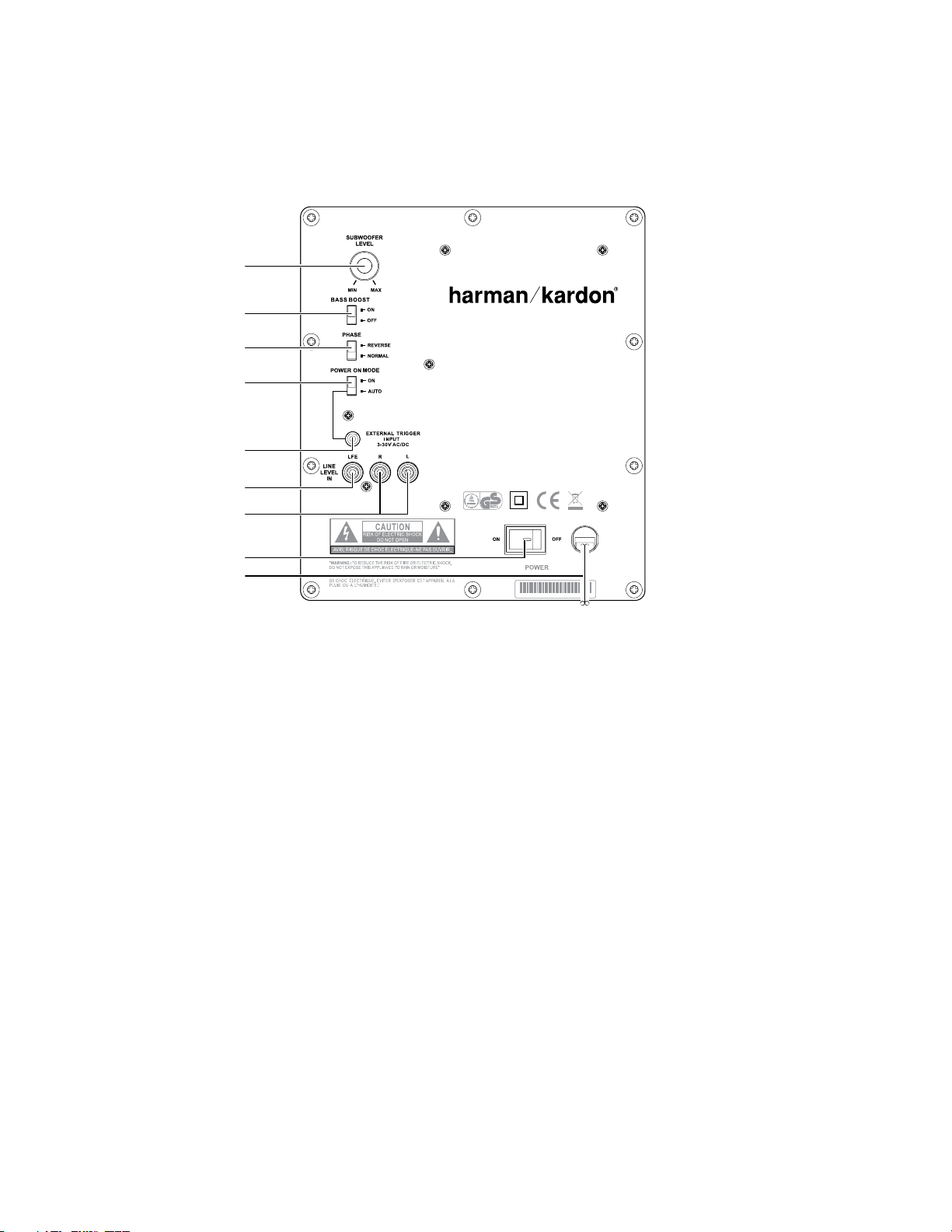
Subwoofer
Level Control
Bass Boost
Switch
Phase Switch
Power On Mode
Switch
External Trigger
Input Connector
Line-Level In
LFE Connector
Line-Level In
L/R Connectors
Power Switch
Power Cord
harman/kardon
SB 10 / 230V Service Manual
Page 3 of 16
Subwoofer Rear-Panel Connections
Subwoofer Rear-Panel Controls
Phase Switch: This switch determines whether the subwoofer driver’s piston-like action
moves in and out in phase with the satellite speakers. If the subwoofer were to play out
of phase with the satellite speakers, the sound waves from the satellites could cancel out
some of the sound waves from the subwoofers, reducing bass performance and sonic
impact. This phenomenon depends in part on the placement of all the speakers relative
to each other in the room.
Bass Boost Switch: Set this switch to “On” to enhance the subwoofer’s low-frequency
performance. Set this switch to “Off” for normal low-frequency performance.
Power-On Mode Switch: When this switch is set in the “Auto” position and when the
Power Switch is set to “On,” the subwoofer will automatically turn itself on when it
receives an audio signal and will enter the Standby mode when it has gone without
receiving an audio signal for 20 minutes. When this switch is set in the “On” position, the
subwoofer will remain on whether or not it is receiving an audio signal.
When the Power-On Mode Switch is in the “Auto” position, the LED light next to the
switch indicates whether the subwoofer is in the On or Standby mode:
When the LED glows blue, the subwoofer is in the On mode. •
When the LED is off, the subwoofer is in Standby mode. •
When the Power Switch is set to “Off,” the LED will not light up, no matter what setting
the Power-On Mode Switch is in.
Subwoofer Level Control: Use this control to adjust the subwoofer’s volume. Turn the
knob clockwise to increase the volume; turn the knob counterclockwise to decrease the
volume.
External Trigger Input Connector: Use the mini-plug of the supplied combination LFE
and trigger cable to connect the External Trigger Input Connector to the trigger output
of another compatible component. Whenever the subwoofer amplifier detects a trigger
signal between 3V and 30V (AC or DC) the amplifier will turn on. The subwoofer
amplifier will turn off after the trigger signal ceases, even when the Power-On Mode
Switch is in the “Auto” position.
Line-Level In LFE Connector: This input bypasses the subwoofer’s internal crossover
circuitry, so use it only with a receiver or processor subwoofer output that has been
low-pass filtered. If your receiver or processor does not have a dedicated subwoofer
output that is low-pass filtered, you should use the subwoofer’s Line-Level In L/R
Connectors instead (see below).
Use the supplied LFE cable (the one with purple connectors) to connect the Line-Level In
LFE Connector to the dedicated subwoofer output of a receiver or preamp/processor.
Line-Level In L/R Connectors: These inputs pass through the subwoofer’s built-in
crossover. Use them if your receiver or preamp/processor does not have a dedicated
subwoofer output that is low-pass filtered.
If your receiver or preamp/processor has a subwoofer output, use the supplied •
LFE/trigger cable to connect it to either one of the subwoofer’s Line-Level L/R In
Connectors.
If your receiver or preamp/processor does not have a separate subwoofer output, •
use two Y-adapters (not supplied). Connect an adapter’s single end to the unit’s
preamp output for that channel. Connect one of the adapter’s dual ends to the
main amp input for that channel, and connect the adapter’s other dual end to
one of the subwoofer’s Line-Level L/R In Connectors. Repeat the process with the
other Y-adapter, preamp channel, main amp input and subwoofer Line-Level L/R
In Connector.
Power Switch: Set this switch in the “On” position to turn the subwoofer on. The
subwoofer will then be in either On or Standby mode, depending on the setting of the
Power-On Mode Switch.
Power Cord: After you have made and verified all subwoofer and speaker connections
described in this manual, plug this cord into an active, unswitched electrical outlet for
proper operation of the subwoofer. DO NOT plug this cord into the accessory outlets
found in some audio components.
6
Page 4
SB 10
SB 10 Soundbar
Listening Position
Subwoofer
600mm
25mm
harman/kardon
SB 10 / 230V Service Manual
Page 4 of 16
Speaker Placement
Speaker Placement
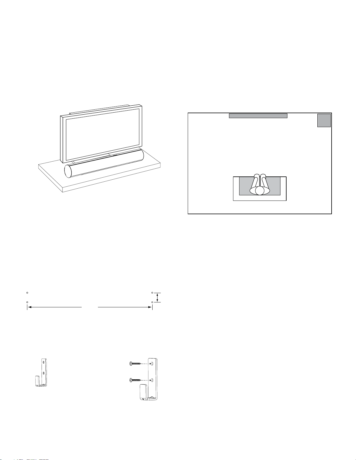
Placing the Soundbar on a Table
If your TV is placed on a table, you can place the soundbar on the table directly in front of
the TV stand, centered with the TV screen. As long as the surface of the table is flat, the
soundbar will rest on its rubber bumpers.
If your TV is located in an entertainment or media center, you can mount the soundbar in
a space directly above or below the TV.
Warning: Do NOT place the soundbar directly on top of a TV or at the front of a table or
cabinet. It could roll forward and injure someone.
Wall-Mounting the Soundbar
If your TV is attached to a wall, you can use the included wall-mount brackets to mount
the soundbar on the wall directly below the TV screen.
Determine the location for the soundbar on the wall. Make sure that the top
1.
of the soundbar will not block your view of the TV screen when it is mounted
on the wall.
Mark the locations of the soundbar wall-mount bracket holes on the wall. The
2.
holes for the left and right brackets are spaced 600mm (23-5/8") apart. The
top and bottom holes for each bracket are spaced 25mm (1") apart. See the
illustration below.
Placing the Subwoofer
Since our ears cannot locate the source of sounds at the low frequencies that the
subwoofer produces, it will perform well from just about any location in your room.
However, you are likely to hear the strongest bass reproduction when you place the
subwoofer in a corner along the same wall as the soundbar.
You can determine the best location for the subwoofer by temporarily placing it in the
listening position and playing music with strong bass content. Move around to various
locations in the room while the system is playing, and listen until you find the location
where the bass performance is best. Place the subwoofer in that location.
(n ot t o sc ale )
NOTE: To ensure that the soundbar will be level, use a carpenter’s level, laser sight or
other device to help you determine that the two sets of holes are at exactly the same
height.
Attach the two wall-mount brackets to the wall at the locations you marked, using
hardware that is appropriate for the wall’s construction and materials. Note that the
soundbar weighs 3.67kg (8.1 lb). Be sure to use hardware that can support this weight.
After making all of the connections described in the Connections section, on page 8,
attach the soundbar to the brackets by sliding the slots in its rubber bumpers onto the
brackets’ vertical tabs.
7
Page 5
SB 10
+–
+–
+–
FRONT
LEFT
+–
+–
SURROUND
RIGHT
CENTER
L C R
–+–+–+
Speaker Wires
(included)
SB 10 Soundbar
Receiver or Amplifier
–+
1. Push Down on
Cap to Open Hole
2. Insert Wire Into
Open Hole
3. Release Cap to
Secure Wire
SUBWOOFER
LFE OUT
+–
+–
+–
FRONT
LEFT
RIGHT
+–
+–
SURROUND
LEFT
RIGHT
CENTER
LFE Cable
(included)
Receiver or Amplifier
Subwoofer
harman/kardon
SB 10 / 230V Service Manual
Page 5 of 16
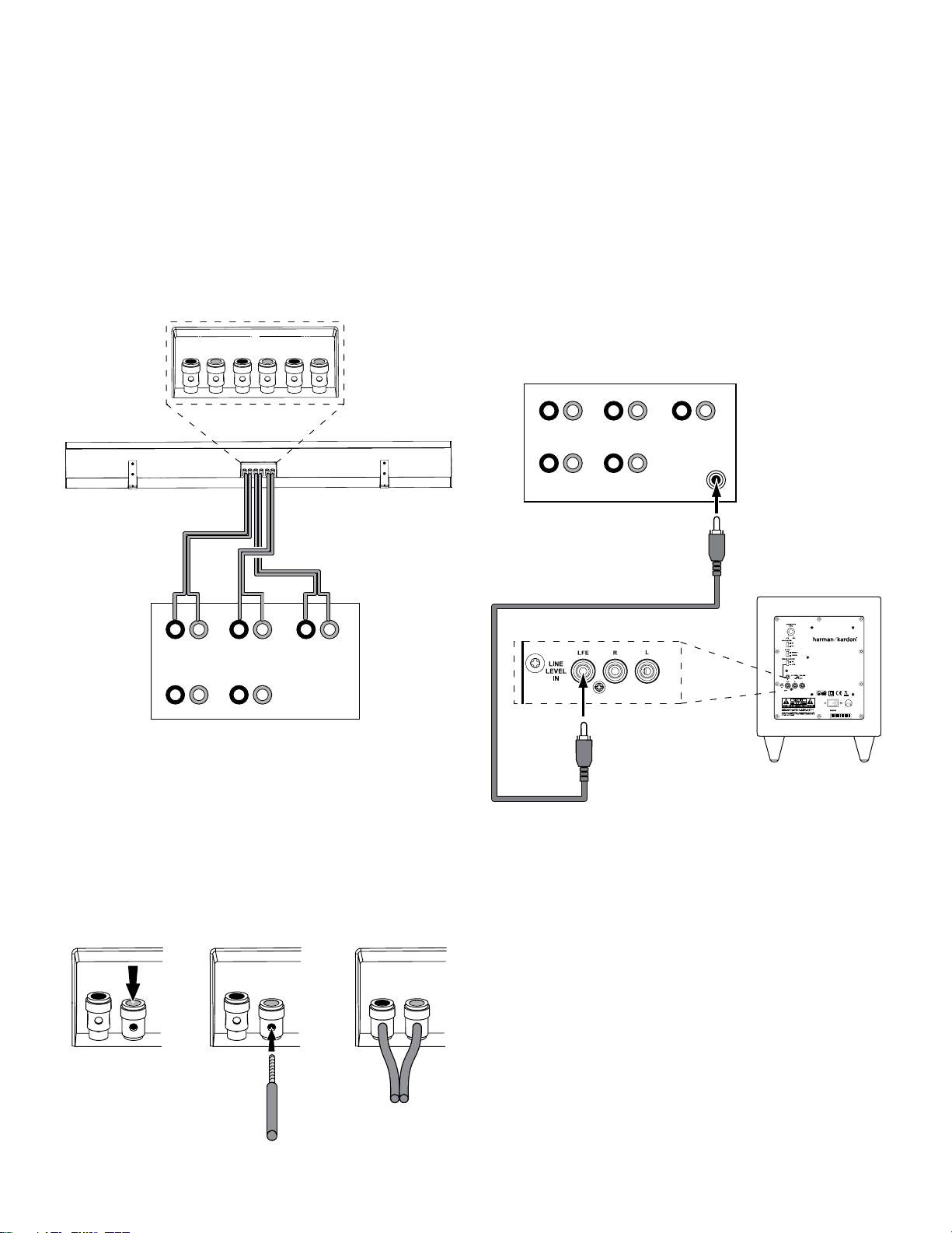
Connections
Connections
CAUTION: Before making speaker connections, be sure that your receiver or amplifier
is turned off. If possible, make sure that its AC cord is unplugged from the AC power
outlet.
Soundbar Connections
The SB 10 soundbar contains left-, center- and right-channel speakers that connect
to your audio/video receiver or amplifier’s front left, center and front right speaker
outputs.
IMPORTANT: Make sure the (+) and (–) bare wires do not touch each other or the other
terminal. Touching wires can cause a short circuit that can damage your receiver or
amplifier.
Subwoofer Connections
1a. If your receiver/processor has a dedicated subwoofer output with low-pass
filtering (also called bass management), use the included LFE cable to connect
the
subwoofer
LFE output) of your receiver or preamp/processor.
Configure your receiver or preamp/processor’s setup menu for Subwoofer ON, and set
the front left, front right, center and surround speakers to Small.
’s Line-Level LFE In jack to the dedicated subwoofer output (or
To connect each wire to the soundbar:
Press down on the terminal cap to open the connection hole on the soundbar’s
1.
speaker terminal.
Insert the wire’s bare end all the way into the hole. Insert the conductor with the
2.
3.
8
colored band into the speaker’s red (+) terminal, and insert the other conductor
into the speaker’s black (–) terminal, as shown in the illustration.
Release the cap to secure the wire.
Page 6

SB 10
PREAMP OUTPUT
+–
+–
+–
FRONT
LEFT
RIGHT
+–
+–
SURROUND
LEFT
RIGHT
CENTER
LEFT RIGHT
LFE Cable
(included)
To Preamp
Outputs
To L/R
Inputs
Mono RCA Cable
(not included)
Receiver or Processor
Subwoofer
PREAMP OUTPUT MAIN AMP INPUT
+–
+–
+–
FRONT
LEFT
RIGHT
+–
+–
SURROUND
LEFT
RIGHT
CENTER
LEFT RIGHT
LEFT RIGHT
LFE Cable
(included)
Stereo Audio Cable
(not included)
Stereo “Y” Cable
(not included)
To Main Amp
Inputs
To Preamp
Outputs
To L/R
Inputs
Mono RCA Cable
(not included)
Receiver or Processor
Subwoofer
harman/kardon
SB 10 / 230V Service Manual
Page 6 of 16
Connections
1b. If your receiver/processor does not have a dedicated subwoofer output but
does have preamp-level (volume-controlled) line outputs, use the included
LFE cable to connect one of those outputs to either of the
subwoofer
’s LineLevel L/R In Connectors. Use an RCA cable (not supplied) to connect the
other receiver or preamp line output to the other
subwoofer
Line-Level L/R
In Connector.
If you’re connecting to a receiver or preamp/processor with left and right line outputs
that are connected to front left and front right amplifier inputs, connect the single ends of
Y-adapters (not supplied) to the receiver or processor’s left and right line outputs. Connect
one of the Y-adapter’s double ends to the subwoofer’s Line-Level L/R In Connectors, and
connect the other double end to your amplifier’s front left and front right inputs.
2. After you have made and verified all other connections, plug the subwoofer’s
Power Cord into an active, unswitched AC outlet. DO NOT plug this cord into
the accessory outlets found on some audio components.
9
Page 7

SB 10
harman/kardon
SB 10 / 230V Service Manual
Page 7 of 16
Operation
Operation
Turning the Subwoofer On and Off
Set the subwoofer’s Power Switch to the “On” position.
If you set the Power-On Mode Switch to “Auto,” the • subwoofer will automatically
turn itself on when it receives an audio signal, and it will go into Standby mode
once it has received no audio signal for 20 minutes. The subwoofer’s LED will
glow blue when the subwoofer is on, and will not light up when the subwoofer is
in Standby mode.
If the Power-On Mode Switch is set to “On,” the •
times. The subwoofer’s LED will glow blue.
If the Ex ternal Trigger Input Connector is connected to a voltage source, the subwoofer
will turn on whenever the source generates a trigger voltage and will go into Standby
mode 10 to 15 minutes after the trigger voltage ceases, regardless of the position of
the Power-On Mode Switch.
If you will not be using the subwoofer for an extended period, set the Power Switch to
the “Off” position.
subwoofer will remain on at all
Subwoofer Adjustments: Volume
Use the Subwoofer Level Control to set the subwoofer’s volume. Turn the knob
clockwise to increase the subwoofer’s volume; turn the knob counterclockwise to
decrease the volume. Once you have balanced the subwoofer’s volume with that of the
other speakers in your system, you shouldn’t have to change it.
Subwoofer Adjustments: Phase
This switch determines whether the subwoofer driver’s piston-like action moves in and
out in phase with the satellite speakers. If the subwoofer were to play out of phase with
the satellite speakers, the sound waves from the satellites could cancel out some of
the sound waves from the subwoofer, reducing bass per formance and sonic impact.
This phenomenon depends in part on the placement of all the speakers relative to each
other in the room.
Although in most cases you should leave the Phase Switch in the “Normal” position,
there is no absolutely correct setting for the Phase Switch. When the subwoofer is
properly in phase with the satellite speakers, the sound will be clearer and have
maximum impact, and percussive sounds like drums, piano and plucked strings will
sound more lifelike. The best way to set the Phase Switch is to listen to music that you
know well and set the switch in the position that gives drums and other percussive
sounds maximum impact.
Subwoofer Adjustments: Bass Boost
When set to the “On” position, the Bass Boost Switch enhances low-frequency
performance. The results: bass with more impact, which you may prefer while
watching movies or listening to music. There is no harm in experimenting with this
control. Setting the switch to the “Off” position will return the subwoofer to its normal
low-frequency performance.
10
Page 8

SB 10
harman/kardon
SB 10 / 230V Service Manual
Page 8 of 16
Troubleshooting
Troubleshooting
This unit is designed for trouble-free operation. Most problems users encounter are due to operating errors. So if you have a problem, first check this list for a possible solution.
If the problem persists, consult your authorized Harman Kardon service center.
Problem Solution
If no sound comes from any of the soundbar speakers: Check that the receiver/amplifier is on and a sound source is playing. •
Make sure that all wires between the receiver/amplifier and the soundbar are •
connected properly.
Make sure that none of the speaker wires is frayed, cut or punctured. •
Review the proper operation of your receiver/amplifier. •
If there is no sound coming from the soundbar’s left or right speaker: Check that the balance control on your receiver/amplifier is not set all the way •
If there is no sound coming from the soundbar’s center speaker: Check your receiver/amplifier’s speaker-setup procedure to make sure that •
If the subwoofer does not turn on: Check that the subwoofer’s Power Cord is plugged into a working AC outlet. •
If there is no sound coming from the subwoofer: Check that the subwoofer’s Power Cord is plugged into a working AC outlet. •
If the system plays at low volumes but shuts off as volume is increased: Make sure that all wires between the receiver/amplifier and the soundbar are •
You can find additional troubleshooting information in the FAQs link on the Support page at www.harmankardon.com.
to one channel.
Check your receiver/amplifier’s speaker-setup procedure to make sure tha t the •
speaker in question has been enabled and that its volume level has not been
turned all the way down.
Make sure that all wires between the receiver/amplifier and the soundbar left •
or right speaker terminals are connected properly.
Make sure that the speaker wires are not frayed, cut or punctured. •
the center speaker has been enabled and its volume level has not been turned
all the way down.
Make sure that all wires between the receiver/amplifier and the soundbar's •
center speaker terminals are connected properly.
Make sure that the speaker wires are not frayed, cut or punctured. •
If your receiver is operating in Dolby •
center speaker is not set to Phantom.
Check that the subwoofer’s Power Switch is in the On position. •
Check that the subwoofer’s Power Switch is in the “On” position. •
Check that the Subwoofer Level Control is not turned all the way down (fully •
counterclockwise).
Check the audio cable connection between your receiver/processor and the •
subwoofer.
Check your receiver/amplifier’s speaker-setup procedure to make sure that •
the subwoofer has been enabled and that its volume level has not been turned
all the way down.
connected properly.
Make sure that none of the speaker wires is frayed, cut or punctured. •
If you have an additional pair of front speakers connected to your receiver/ •
amplifier, make sure that you’re not operating the system below the receiver/
amplifier’s minimum impedance requirements. Check the receiver/amplifier’s
documentation for more information.
®
Pro Logic® mode, make sure that the
11
Page 9

SB 10
harman/kardon
SB 10 / 230V Service Manual
Page 9 of 16
Specifications
SB 10 system
Frequency response: 45Hz – 20kHz (–6dB)
SB 10 soundbar speaker
Low-frequency transducer
Left:
Right:
Center:
High-frequency transducer
Left:
Right:
Center:
Recommended power handling
Left –Right:
Center:
Nominal impedance: 8 ohms (each channel)
Sensitivity (2.83V/1m): 84dB (each channel)
Crossover frequency: 2.2kHz, 24dB/octave
Connector type: Push-spring terminal
Enclosure type: Sealed
Finish: Gloss black
Dimensions (H x W x D): 4-5/16" x 36-1/4" x 3-1/2"
Weight: 8.1 lb (3.67kg)
Powered Subwoofer
Low-frequency transducer:
Amplifier power: 200 watts
Frequency response: 45Hz – 200Hz (–6dB)
Controls: Volume, phase, bass boost
Connections: LFE input, left and right RCA line-level inputs
Enclosure type: Sealed
Finish: Gloss black
Power requirement: AC 100 ~ 120V, 50/60Hz, 200W or
Power consumption: <1W (standby); 200W (maximum)
Dimensions (H x W x D): 13-29/32" x 10-1/2" x 10-1/2"
Weight: 19.8 lb (9kg)
3" (76mm) paper cone, video-shielded
3" (76mm) paper cone, video-shielded
Two 3" (76mm) paper cones, video-shielded
3/4" (19mm) silk dome, video-shielded
3/4" (19mm) silk dome, video-shielded
3/4" (19mm) silk dome, video-shielded
60 watts (each)
100 watts
(110mm x 920mm x 89mm)
8" (203mm) down-firing cone, video-shielded
AC 220 ~ 240V, 50/60Hz, 200W
(353mm x 267mm x 267mm)
Specifications
12
Page 10

harman/kardon
SB 10 / 230V Service Manual
Page 10 of 16
Page 11

harman/kardon
SB 10 / 230V Service Manual
Page 11 of 16
Page 12

harman/kardon
SB 10 / 230V Service Manual
Page 12 of 16
Page 13

Date
harman/kardon
SB 10 / 230V Service Manual
Page 13 of 16
2010.09.27
Editions
1
Page
1
Client: harman/kardon
Exploded View Instruction
Model: SB 10SUB/230
7
6
9
1
Item
1
241-080-05531-0BAE
2
010-0N20-05317-E
3
352-FM04020D605-E
Part Name
8
5
Description
Cabinet
Amplifier
Screw
3
2
4
Q'ty
1
1
16
4
24MR11DZA-DW01-E
5
320-SR-05226-0BAE
6
316-AG-00557-E
7
413-000-05591-E
8
321-ABS-05141-0BAE
9
162-A025D023-E
8" Subwoofer
Rubber Feet
LogoBadge
Static Label
Plastic Feet
LED+Cable
1
4
2
2
4
1
Page 14

1
harman/kardon
SB 10 / 230V Service Manual
Page 14 of 16
A A
2
LFENORMAL
3
4
B B
TO MAIN PCB
C C
D D
GND GND
CN100
2
1
G S
CON2.5-2
GND
G2 G1
3
5 641 2
SW100
INPUT
GND
GND
J100
1
2
3
4
CON2.0-4
J101
1
2
3
4
CON2.0
-4
Title
Number RevisionSize
A4
Date: 2010/8/3 Sheet of
File: D:\HKTS200\DV1\LFE_SW.SchDoc Drawn By:
1
2
3
4
Page 15

1
harman/kardon
SB 10 / 230V Service Manual
Page 15 of 16
2
3
4
5
6
7
8
JK1
L
GND
A A
B B
GND
R
LFE
RCA-3P 2
C78
100P
GND
GND
C34
5
+
22u/16
GND
C39
22u/16
C42
22u/16
+
+
BEAD-600
22uF/16V
C48
C53
B5
C46
22u/16
C37
220P
C41
220P
C44
220P
+
22u/16
+
GND
4
1
3
2
MCU3.3V MCU3.3V
R36
4.99K 1%
R39
49.9K 1%
+
180P
C54
3.3VAD
C55
180P
GND
GND
GND
C47
104
C56
1uF/25V
R23 10K
R24
10K
R27
10K
+
R21 10K
C35 100P
6
7
O
5
+
U1B
TL072
GND GND
GND
B4
BEAD-600
10
9
8
7
6
VA
GND
AINR
VQ
AINL
CS5343
C57
104
C58
104
SDOUT
SCLK
LRCK
MCLK
FILT+
R25 5K
3
1
VR1
1KA
D3.3V
R33
10K
U2
1
2
3
4
5
+
C59
1uF/25V
R34
R35
R37
R38
GND GND
B8
BEAD-600
-7V
C60
104
GND
B9
C62
C C
CN6
1
2
3
4
CON2.5-4
EN VOUT
Hi
Low 0V
BEAD-600
104
+7V
GND
STB
3.3V
C74
104
MCU3.3V
D D
-7VA
R46
0
C61
104
GND
U5
AP6209
+7VA
R49
0
VI3VO
_3.3V
GND1VO
3.3V
2
4
+
C64
22uF/16V
U7
+7VA SW3.3V
AP6209_3.3V B13
VI1VO
4
GND2EN
NC
GND
GND
Q3
E C
R58
47K
B
R59
4K7
R53
10K
MMBT 3906
C65
22uF/16V
104
GND
5
3
10K
GND
R57
C72
104
+
GND
C75
22uF/16V
GND
B10
BEAD-600
+
C66
BEAD-600
TXD
1
2
100
100
100
100
GND
GND
-7VA
SD0
BICK
LRCK
MCLK
3
R22 100K
C36 100P
C38 104
2
3
+7VA
SD0
BICK
LRCK
MCLK
C63
104
R52
OPT
C73
104
B-
B+
U1A
8 4
TL072
C43 104
+
C45
MCU3.3V
+3.3V
1
22u/16
GND
GND
C40
+
22u/16
R31
50K
GND GND
MCU3.3V
CN3
1
2
3
EQ
R26 10K
R45
100
GND
JK2
PHONE
4
1 2
3
RST
VCC
VSS
1
U4
STM809-3.3V
GND
SCL
SDA
MCU3.3V
C69
104
AUTO ON
ZD1
3.3V
2
B11
BEAD-600
C70
104
1
3
2
GND
POWER GOOD
309A_PWRDN
C71
18P
GND
6
5
4
R55
22K
MCU3.3V
EAPD#
MCLK
POWER GOOD
309A_PWRDN
STB
R50
100K
1 2
XL1
12.288MHZ
2 4
U6
3 5
NC7SZ04M5X_NL
MCU3.3V
R54
10K
9
8
PLUG_DET
7
D1
1
ES1G
5
ONAUTO
G2 G1
GND GND
R28 10K
SW1
3
5 641 2
PWR
PWR MODE PHASEBASS
POWER ON MODE PHASEBa
MCU3.3V
MCU3.3V
U3
RST
RxD/P3.0
TxD/P3.1
XTAL2
XTAL1
INT0/P3.2
INT1/P3.3
T0/P3.4
T1/P3.5
GND
C68
OPT
MCLK
C50
104
CN4
ISP
B14
BEAD
C51
104
P1.7/SCLK
P1.6/MISO
P1.5/MOSI
P3.7/CEX0/PWM0
MPC82L52AT
1
2
3
4
VCC
P1.4/SS
P1.3
P1.2
P1.1
P1.0
10uF/16V
C49
10uF/16V
R40
10K
EAPD#
R43
R51
10K
C67
18P
+
TXD
0
10
GND
TXD
MCU3.3V
B12 120R
1
2
3
4
5
6
7
8
9
GNDGND
GND
GND
LO HI
NO PLUG PLUG IN
TRIGGER
C76
104
R56
22K
ZD2
3.3V
1 2
GND
G2 G1
GND GND
3
5 641 2
R30 10K
MCU3.3V
ss Boostor
MCU3.3V
R41
10K
RESET#
LED
AUTO ON
TRIGGER
PLUG_DET
BASSPHASE
PWR MODE
R42
10K
B6
RESET#
+
C52
20
19
18
17
16
15
14
13
12
11
MCU3.3V
6
ONOFF
G2 G1
SW2
BASS
GND GND
5 641 2
R29 10K
MCU3.3V
MCU3.3V
10K
2
1
0
0
1(AUTO)
1
110
GND
0
0
0
0
R60
0(ON)
0
0
X X X
1
1
BEAD-600
TO LFE SW PCB
B7
BEAD-600
SCL
SDA
PLUG_DET
TIGGER
PWR MODE
AUTO ON
STB
LED
CN7
G S
CON2.5-2
SCL
SDA
1(AUTO)
AUTO OFF TIME=15 MIN
GND
R47
2.7K
CN5
1
2
CON2.0
Q2 2N3904
2 1
R48
10K
Hi
Lo
HKTS200SUB
Number RevisionSize
7
3
LED
ON
OFF
LED
Title
A3
Date: 2010/8/3 Sheet of
File: D:\HKTS200\DV1\INPUT_DV1.SchDoc Drawn By:
3
REVERSENORMAL
SW3
PHASE
101
X X
0 1
-2
GND
EAPD#
1
10
J1
CON2.0-4
8
1
2
3
4
LFE 1
NOR 0
Page 16

1
harman/kardon
SB 10 / 230V Service Manual
Page 16 of 16
2
3
4
5
6
7
8
A A
CN1
1
GND
23
19
20
21
22
24
28
25
27
26
29
30
31
32
33
34
35
36
1
2
3.96
IC1
VL
GNDREF
GNDR1
VDD
VDD
CONFIG
TWARN
PWRDN
FAULT
TRI-STATE
IN-LA
IN-LB
IN-RA
IN-RB
VSS
VSS
VCC SIGN
VCC SIGN
GND SUB
STA516B
59
GND
VDD
NC
FILTER_PLL21GNDA
22
58
23
24
GND
55
56
LRCKO
SDO_1257SDO_34
STA309A
CKOUT
VDDA
25
26
BICKO
NC
+3.3V
54
NC
GND
27
R1
2K
C2104
50
49
51
52
GND53VDD
EAPD
OUT1_B
OUT1_A
EAPD#
IC2
OUT2_A
OUT2_B
GND
VDD
OUT3_A
OUT3_B
OUT4_A
OUT4_B
OUT5_A
OUT5_B
GND
VDD
OUT6_A
OUT6_B
R3
NC
48
47
46
NC
45
44
43
42
41
40
39
38
37
NC
36
35
34
33
EAPD
3
R4
NC
Q1
NC
1 2
GND
C10
+
10uF
C13
104
+3.3V
CH5A
CH5B
C18
104
+3.3V
+3.3V
TWARN
EAPD
B15
BEAD-600
GND
R5
10K
R11
10K
C15
104
GND
C3
104
C6
104
CH5B
CH5A
GND
VDD
OUT7_A32OUT7_B31OUT8_A30OUT8_B
28
29
B2
GND
C33
104
+3.3V
SGND
BEAD-600
C27
C28
104
22uF
B3
BEAD-600
+3.3V
C29
104
GND
GND
C23
104
C24
104
+3.3V
+3.3V
C1104
R2
10K
NC
GND
GND
+3.3V
+3.3V
C20
104
C25
R15
R17
NC
309A_PWRDN
C4
1N2
GND
1
MVO
2
GND
3
VDD
4
GND
5
NC
6
SDI_78
7
SDI_56
8
SDI_34
9
SDI_12
10
LRCKI
11
BICKI
12
VDD
13
GND
14
NC
15
RESET
16
PLLB
0R16
OPT
0
C26NC
C30
1N2
GND
100PF
62
63
61
64
60
NC
PWDN
SDO_56
SDO_78
XTI
SDA18SCL19SA
20
17
R20
3K3
C31
C32
100PF
SGND
309A_PWRDN
B B
R7
+3.3V
R8 0
GND
C11 104
GND
SD0
MCLK
SDA
SCL
LRCK
BICK
GND
RESET#
C19
104
R12 0
R13 0
R14 0
R18
R19
GND
C22
47P
0
0
SD0
LRCK
BICK
+3.3V
C C
RESET#
MCLK
SDA
SCL
+47V
PGND
2
B1
COILS-4
4
31
GND
OUT 1A
OUT 1A
OUT 1B
OUT 1B
OUT 2A
OUT 2A
OUT 2B
OUT 2B
VCC 1A
VCC 1B
VCC 2B
VCC 2A
PGND 1A
PGND 1B
PGND2A
PGND2B
NC
PVCC_S
18
17
16
11
10
9
8
3
2
15
12
7
4
14
13
6
5
C79
GND
GND
SUB ++
SUB--
1U/100V X7R
1U/100V X7R
C80
GND
1U/100V X7R
L1
22UH
C7
330PF/100V
R9
22R
R32
22R
C77
330PF/100V
L2 22UH
C16
GND
C21
1U/100V X7R
C5 104/100V X7R
GND
C14 104/100V X7R
+
C17
1000U/63V
104/100V X7R
R6
6.2R
R10
6.2R
104/100V X7R
PVCC_S
PVCC_S
SUB +
SUB-
C8
C12
CN2
1
C9
2
684
4 OHM
D D
Title
HKTS200SUB
Number RevisionSize
A3
Date: 2010/8/3 Sheet of
1
2
3
4
5
6
File: D:\HKTS200\DV1\AMP_DV1.SCHDOC Drawn By:
7
8
 Loading...