

Page 1
PA5800/Signature 2.1
Multichannel Power Amplifier
TECHNICAL MANUAL
Harman Consumer Group
250 Crossways Park Drive
Woodbury, N.Y. 11797
1-800 645-7484
A Harman International Company
Part No.: 1112-PA5800/2.1 Rev A 7/99
Page 2

Multichannel Power Amplifier Harman Kardon PA5800 / SIGNATURE 2.1
TABLE OF CONTENTS
FEATURES......................................................................1
SPECIFICATIONS...........................................................2
FRONT PANEL CONTROLS .........................................3
PA5800/Signature 2.1
REAR PANEL CONNECTIONS......................................4
INSTALLATION ...............................................................4
OPERATION....................................................................6
IDLE CURRENT ADJUSTMENT ....................................6
PA5800/Signature 2.1
TROUBLE SHOOTING ...................................................7
PROTECT MODE ...........................................................7
PA5800 MECHANICAL EXPLODED VIEW ...................8
PA5800 MECHANICAL PARTS LIST.............................9
PA5800 PACKING EXPLODED VIEW ...........................9
PA5800 POWER SWITCH PCB....................................16
PA5800 POWER AMPLIFIER PCB ...............................17
Signature 2.1 POWER SWITCH/INDICATOR PCB ......18
Rev B9 & D
Signature 2.1 POWER AMPLIFIER PCB ......................19
PA5800 (120V) TRANSF. WIRING REV B...................20
Signature 2.1 (120V) TRANSF. WIRING ......................21
Signature 2.1 (230V) TRANSF. WIRING REV 0 ..........22
Signature 2.1 (230V) TRANSF. WIRING REV B ..........23
INTEGRATED CIRCUITS ..............................................24
PA5800 POWER SWITCH SCHEMATIC (1 of 1).........25
PA5800 POWER AMPLIFIER SCHEMATIC (1 of 1)....26
Signature 2.1 POWER SWITCH/INDICATOR...............27
SCHEMATIC (1 of 1)
Signature 2.1 MECHANICAL EXPLODED VIEW .........10
Signature 2.1 MECHANICAL PARTS LIST ...................11
Signature 2.1 PACKING EXPLODED VIEW .................11
PA5800 ELECTRICAL PARTS LIST .............................12
Signature 2.1 ELECTRICAL PARTS LIST ....................14
Signature 2.1 POWER AMP SCHEMATIC (1 of 5) ......28
Signature 2.1 POWER AMP SCHEMATIC (2 of 5) ......29
Signature 2.1 POWER AMP SCHEMATIC (3 of 5) ......30
Signature 2.1 POWER AMP SCHEMATIC (4 of 5) ......31
Signature 2.1 POWER AMP SCHEMATIC (5 of 5) ......32
FEATURES
The Harman Kardon PA5800/Signature2.1 is a flexible, state-of-the-art audio power amplifier designed to deliver high
performance for use in home theater or music reproduction applications. The following are among its many features:
n
Designed and manufactured in the United States.
n
High-current output capability.
n
Toroidal Power Transformer with individual secondary
wiring and individual DC power supplies for each
channel assure maximum output and minimum interaction
between channels.
n
Ultrawide Bandwidth Design
n
Low Negative Feedback
n
Low Harmonic and intermodulation distortion
n
High-current power supply
n
Massive Heat Sinks for quiet convection cooling
n
Remote Turn-on/Turn-off circuitry with select Harman
Kardon product or through optional accessories
1
Page 3

Multichannel Power Amplifier Harman Kardon PA5800 / SIGNATURE 2.1
SPECIFICATIONS
PA5800
Power Requirements: ..................120V version: 120VAC, 50/60Hz
230V version: 230VAC, 50Hz
High Current Capability: ................73Amps
Power Output: .......................5x80watts @ 8 ohms
20Hz - 20KHz, <0.05% THD, All Channels Driven
Frequency Response: .................0.22Hz - 160kHz - 3dB at 1 watt
THD/IMD: ..........................Less than 110 at rated output
Power Bandwidth: ....................<5hz - 160kHz
Input Sensitivity: .....................1volt for rated output
Input Impedance: .....................33kohms
Remote Trigger Voltage: ................6-12volts DC (tip of plug must be “positive”(+))
Remote Trigger Impedance: .............20Kohms
S/N Ratio (unweighted): ................>100dB
S/N Ratio (weighted): ..................>115dB
Channel Separation
(1kHz):........................>95dB
(10kHz) .......................>80dB
Damping Factor
(40Hz):........................1.54%
(1hz):.........................1.46%
Idling Power Consumption: ..............26watts
Full Power Consumption: ...............773watts
Dimensions (H xWxD):...............6-1/8 x 17-3/8 x 15-1/2 inches
155 x 440 x 394 mm
Weight: ...........................30lbs/13.6 kg
Signature 2.1
Power Requirements: ..................120V version: 120VAC, 50/60Hz
230V version: 230VAC 50Hz
Power Output: .......................5x100watts @ 8 ohms
20Hz - 20kHz, <0.03% THD, All Channels Driven
5 x 150 watts @ 4 ohms
20Hz - 20kHz, <0.03% THD, All Channels Driven
High-Current Capability: ................100Amps
Frequency Response: .................<1hz - >160kHz
Power Bandwidth: ....................<1hz - >160kHz
THD/IMD: ..........................<0.03% at rated output
Crosstalk ..........................<-87 dBr between any two channels at maximum output
Negative Feedback: ...................<25dB
Input Impedance: .....................33Kohms
Input Sensitivity: .....................1volt for rated output
Remote Trigger Voltage: ................6-12volts DC (tip of plug must be “positive”(+))
Remote Trigger Impedance: .............20Kohms
Dimensions (H xWxD):...............7½x17¼x15¼inches
191 x 438 x 387 mm
Weight: ...........................47lbs/21 kg
2
Page 4
Multichannel Power Amplifier Harman Kardon PA5800 / SIGNATURE 2.1
PA 5800
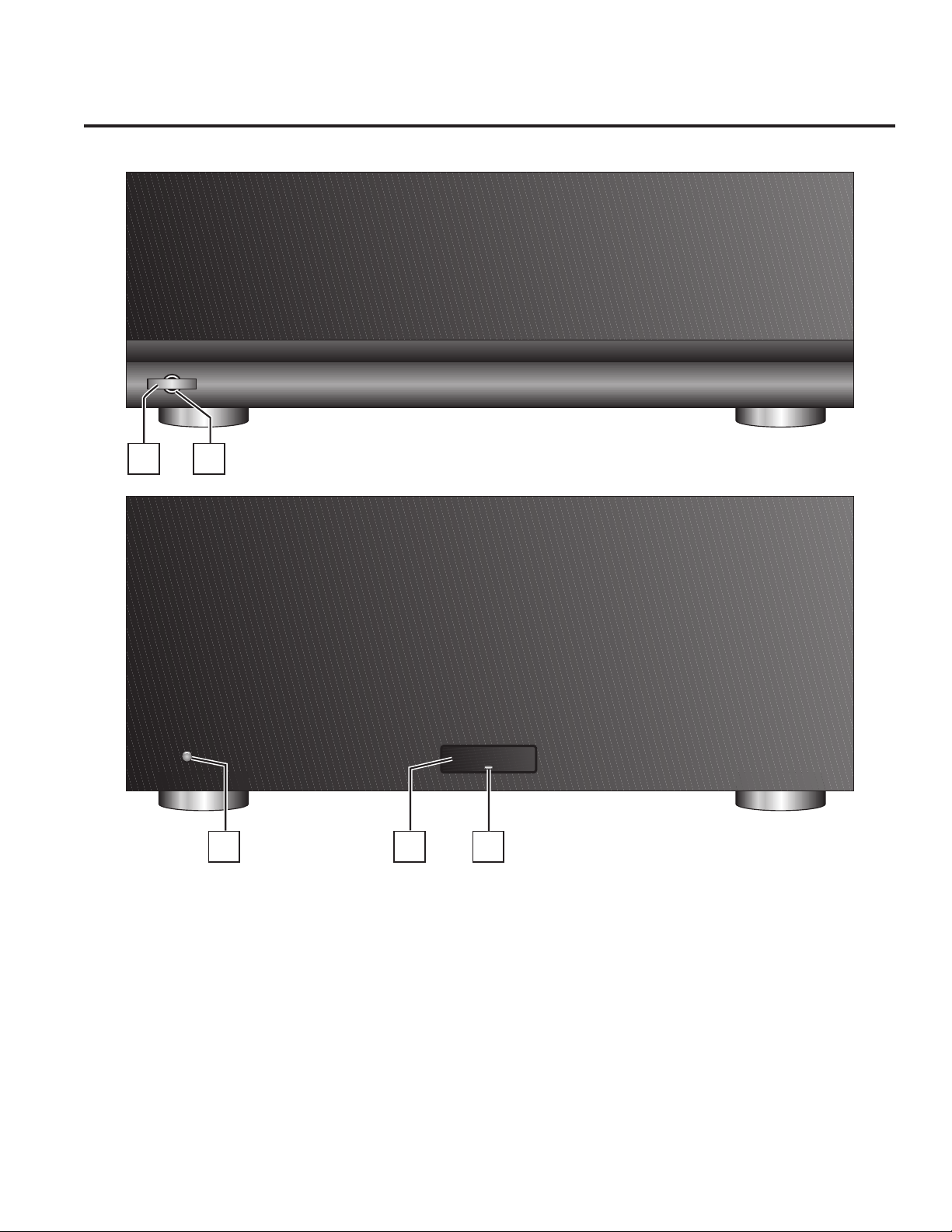
Signature 2.1 & PA5800 FRONT PANEL CONTROLS
harman/kardon
Power
1
harman/kardon
PA 5800
2
2.1
On/Off
S
134
1. Power Switch: Press this switch to turn the
PA5800/Signature 2.1 on for manual operation, or place it in
the standby mode for automatic/remote turn-on when the
unit in connected to a device with a compatible trigger
circuit.
2. Power On Indicator: The color of this indicator varies
with the status of the PA5800. It is red when the unit is off
and in manual operation, amber in standby mode for
automatic/remote turn-on when the PA5800 is connected to
a device with a compatible trigger circuit, and green when
the unit is on.
IGNATURE
series
3. Power On Indicator: When the word Signature is
illuminated in blue, the 2.1 is in a normal operating
condition.
4. LED Indicator: The color of this indicator varies with the
status of the 2.1. It is red when the unit is off and in manual
operation, amber in the standby mode, and flashing green
during warm-up. If the indicator flashes and alternates
between red and amber, the 2.1 is in the protect mode,
indicating a problem in the unit or connections to the
speakers.
3
Page 5
Multichannel Power Amplifier Harman Kardon PA5800 / SIGNATURE 2.1
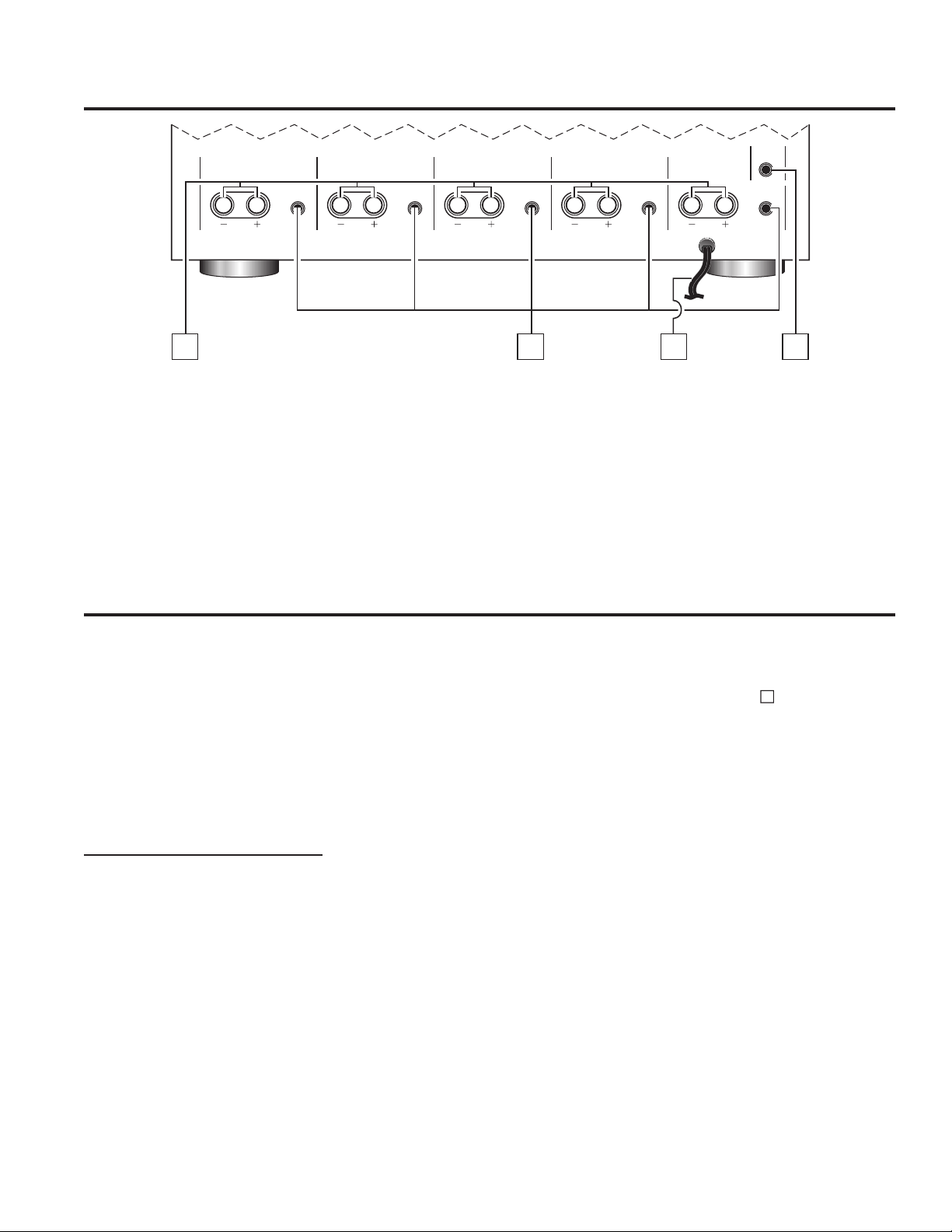
REAR PANEL CONNECTIONS
POWERAMP
CHANNEL ONE (FRONT RIGHT)
SPEAKER SPEAKER SPEAKER SPEAKER SPEAKER
CHANNEL TWO (SURROUND RIGHT)
12345
IN IN IN IN IN
CHANNEL THREE (FRONT CENTER)
CHANNEL FOUR (SURROUND LEFT)
CHANNEL FIVE (FRONT LEFT)
TRIGGER IN
4 OHMS 4 OHMS 4 OHMS 4 OHMS 4 OHMS
5. Speaker Outputs: Connections from these terminals
should be made to the appropriate speakers in your system.
6. Audio Inputs: Connect the outputs of the PT2500,
ADP303 or other surround processor, preamplifier or
decoder to these jacks.
INSTALLATION
NOTE: When making any connections between source
components, processor or preamplifiers and the
PA5800/2.1, or when making any connection to speakers,
be certain that both the input device and the unit are turned
off. To ensure that there will be no unwanted signal
transients that can damage equipment or speakers, it is
always best to unplug all equipment from AC power outlets
before making any connection . Modern electronic products
often have a “standby” mode that may be activated even
though the product may appear to be turned off.
Power Control Connections
The Harman Kardon PA5800/2.1 amplifier features a built-in
remote turn-on system that will automatically turn on the
amplifier when another devices in the system are switched
on. To activate this system, this amplifier must be used in
conjunction with a Harman Kardon PT2500, other
compatible Harman Kardon products or other approved
devices.
NOTE: Before making any connections to remote trigger
outlets, it is critical that both the PA5800/2.1 and the
triggering device be turned off. For additional safety, it is
best that these connections be made while both products
are unplugged from AC power sources.
~
AC 120V/60Hz
AC INPUT
6785
7. AC Power Cord: Connect this plug to a wall-mounted AC
outlet. Due to the current draw of the PA5800/2.1, it is NOT
recommended that the accessory outlets on the back of the
audio/video components be used to power this product.
8. Remote Amp Trigger In: Connect this jack to the
matching trigger output on a PT2500 or other compatible
device to have the PA5800/2.1 automatically turn on when
the devices are activated.
Remote Turn-On Compatible Harman Kardon
Products - Including the PT2500
Connect one end of the accessory cable supplied with the
PT2500 to the Remote Amp Trigger in jack on the rear of
the PA5800/2.1. Connect the other end to the jack on the
PT2500 that carries the same identification.
Remote Turn-On Using External AC-to-DC
Converter
If the PA5800/2.1 is not used with a compatible Harman
Kardon product, it is still compatible to activate the unit for
automatic turn-on.
To control the amplifier in this manner you will need a small
UL/CSA approved class 2 AC-to-DC power converter
capable of delivering a 6 to 12-volt DC signal. The DC
voltage should terminate in a standard 3.5 mm mono
miniplug, with the tip of the plug “positive” (+). This type of
converter may be obtained as a “Power Adapter” from many
electronic retailers. Consult your dealer for further
information.
Plug the AC adapter into a switched outlet that will be
activated when you wish to have the amplifier turn on. This
may be the switched outlet at the rear of an AV receiver or
other audio equipment, an AC outlet that is part of a current
sensing control unit activated by a preamp or surround
processor or a switched AC wall outlet.
8
4
Page 6

Multichannel Power Amplifier Harman Kardon PA5800 / SIGNATURE 2.1
Connect the 3.5mm miniplug from the power converter to
the Remote Amp Trigger in jack on the rear of the
PA5800/2.1.
8
Audio System Connections
As a general rule, avoid running any input signal or speaker
wire connections next to or parallel with AC power cords.
This may cause undesired hum or other interference that
will greatly degrade signal performance.
When making connections with RCA-type plugs on
interconnect cables, make certain to gently but firmly insert
the plugs into the jacks on the rear of the PA5800/2.1.
Loose connections can cause intermittent sound and may
damage your speakers.
Connect the outputs of the PT2500 or your surround
processor to the audio inputs of the PA5800/2.1 . To
simplify installation, it is best to follow the markings on the
rear panel by connecting the Front Right output of the
PT2500 to the Front Right input on the PA5800/2.1,
following the same pattern for each channel.
Important Note: The PA5800/2.1 is not designed for
use in Bridged configuration. Do not connect the same
input or speaker to more than one channel.
To ensure that the high-quality signals produced by the
PA5800/2.1 are carried to your speakers without loss of
clarity or resolution, we recommend that you use
high-quality speaker cable. Many brands of cable are
available and the choice of cable may be influenced by the
distance between your speakers and you amplifier, the type
of speakers you use, personal preferences and other
factors. Your dealer or installer is a valuable resource to
consult in selecting a proper cable for connections between
your amplifier and speakers.
Regardless of the brand or type of cable selected, we
recommend that you use a cable construction of fine, multi
strand copper with a gauge of 14 or smaller. When
specifying cable, remember that the lower the number, the
thicker the cable.
Cable with a gauge or 16 may be used for short runs of less
than ten feet. We do not recommend the use of cables with
an AWG equivalent of 18 or higher due to the power loss
and degradation in performance that will occur.
Cables that run inside walls should have the appropriate
markings to indicate listing with UL (“CL-2/CL-3”), CSA
(“FT-4”) or appropriate safety agency standards that may
require in your area. Questions about running cables inside
walls should be referred to you installer or a licensed
electrical contractor who is familiar with the NEC and/or the
applicable building or electrical code in your area.
6
Connections to Speakers
The final step of the installation process is to connect the
amplifier to your speaker using high-quality cable. A pair of
binding posts is provided for each channels output. These
posts will accept bare wire or banana-type plugs.
Note that one conductor of the speaker cable will have no
markings or an indication of “-” for negative polarity, and the
other will have a read line, brand-names markings, a
colored thread or some other positive-polarity indication.
The wire with the positive indication should be connected to
the red terminals on both the PA5800/2.1 and your
speakers. The negative wire should be connected to the
black terminal on the PA5800/2.1 and the speakers.
If bare wire is used for connections, strip approximately ¾”
(20mm) of insulation from the end of each wire and carefully
twist the strands of each conductor together. Be careful not
to cut the individual strands or twist them off; for optimal
performance, all strands must be used.
Next loosen the knobs of the speaker output terminals far
enough so that the cap moves back on its threads past the
U-shaped groove at the back end of the terminal. Making
certain that you observe polarity by connecting the negative
(-) wire to the black terminal and the positive(+) wire to the
red terminal, pass the exposed wire through from the top of
the slot until the wire is visible from the bottom end. Holding
the wire in place, twist the cap back so that the connection is
secured. Do not overtighten or use tools, as this may
damage the plastic terminal cap or break the delicate wire
strands and decrease system performace.
Important Note: When making speaker wire
connections, be cartain that none of the strands from one
lead touch any other lead. This will cause a short circuit and
may damage your amplifier or speakers. Damage from
short circuits caused in this manner is not covered by the
product warranty.
Connections may also be made using standard 4mm 0D
banana plugs. Before using a banana-type jack, make
certain that the plastic screw caps on the PA5800/2.1 are
firmly tightened by turning them clockwise until they are
snug against the chassis. This will ensure that the maximum
surface area of the plug is in contact with the jack. Once the
wire has been attached to the banana plug following the
plug manufacture’s instructions, simply insert the banana
plug into the hole provided on the rear of the colored screw
caps on the terminal posts. Be certain to observe proper
polarity.
Finally, run the cables to the speaker locations. It is highly
recommended that the length of cable connecting any pair
of speakers be identical. For example, make certain that the
cable length connecting left and right front or left and right
rear (surround) speaker is identical, even though one
5
Page 7

Multichannel Power Amplifier Harman Kardon PA5800 / SIGNATURE 2.1
speaker may be physically closer to the amplifier than the
other. Do not coil any excess cable, as this may become an
inductor that creates frequency response variations in your
system.
Connect the wire to the speaker, again being certain to
observe proper polarity. Remember to connect the negative
or black wire to the matching terminal on the speaker.
Similarly, the positive or red wire should be connected to the
like terminal on the speaker.
OPERATION
The PA5800/2.1 may be operated in either a manual or
automatic mode. If the unit is being used in a stand-alone
operation you should follow the instructions below for
Manual Operation. When the PA5800/2.1 is connected to
another compatible device such as the Signature 2.0 or
PT2500 tuner, follow the instructions for Automatic
Operation.
Make sure the power switch is in the off position before
plugging in the AC power cord. After all the connections
have been made to the amplifier’s input jacks and speaker
terminals, connect the power cord to an AC outlet. Turn on
your source component and receiver/processor first; start
with a low volume level to protect your speakers.
Manual Operation
The LED indicator should be glowing red if the unit is
plugged in. Press the front panel switch to turn the unit on.
NOTE: While most speaker manufacturers adhere to an
industry standard of using black terminals for negative and
red for positive, some manufacturers may not adhere to this
configuration. To ensure properly phased connections and
optimal performance, consult the identification plate on your
speaker terminals, of the speaker’s manual to verify polarity.
If you do not know the polarity of your speaker, ask your
dealer or installer for advice before proceeding, or consult
the speaker’s manufacturer.
Automatic Operation
Before proceeding, make certain the connection between
the Signature 2.0, PT2500, or other trigger source has been
connected properly to the unit following the previous
directions. At this point the trigger source should be off.
After all cables are connected and the PA5800/2.1 is
plugged in, the LED Indicator should be glowing red. Press
the power switch and the indicator will turn amber indicating
the unit is in the standby mode and ready to turn on when it
receives a signal from the triggering device. Finally, turn on
your Signature 2.0, PT2500, or other trigger source to turn
the PA5800/2.1 on.
PA5800 - The indicator surrounding the power switch will
turn green after a brief pause.
Signature 2.1 - The indicator will flash green briefly, and
then go out; the front panel will then illuminate to blue.
PA5800 - The indicator surrounding the power switch will
turn green after a brief pause.
Signature 2.1 - The indicator will flash green briefly, and
then go out; the front panel will then illuminate to blue.
To turn the unit off, press the power switch again. The LED
indicator will return to red.
IDLE CURRENT ADJUSTMENT PA5800/Signature 2.1
Locate test points:
PA5800 - P75A, P75B, P75C, P75D, P75E
Signature 2.1 - P2, P4, P6, P8, P10
These are 2 pin female molex connectors (5 total, 1 per
channel) on the MAIN AMPLIFIER PCB.
Attach a DC voltmeter (set to a low range) to these points.
This is best accomplished by making up a “test plug” using a
male molex connector that fits into the one in the unit, with
wires attached, for connection to the voltmeter. An
alternative method is to use two “mini-grabbers” to attach to
At the conclusion of your listening session, there is no need
to turn the PA5800/2.1 off manually. When the Signature
2.0, PT2500, or other trigger source is turned off, the
PA5800/2.1 will return to the standby mode.
Important Note: If you will not be using your audio
system for an extended period of time, such as a vacation,
we recommend turning the PA5800/2.1 off using the power
switch.
the two outer pins on each connection. Warning: Do not
accidentally short the two points together with a meter probe
during adjustment.
Adjustment Points:
PA5800 - R70A, R70B, R70C, R70D, R70E
Signature 2.1 - R22, R55, R103, R151, R199
Adjust to 25mv across test points, one channel at a time
until all channels comply.
6
Page 8

Multichannel Power Amplifier Harman Kardon PA5800 / SIGNATURE 2.1
PROTECT MODE
Input/Output Protection
Under some conditions, such as a shorted speaker wire, DC
voltage on an input connection or thermal overload, the
amplifier will place itself in a “protect mode” to prevent
damage to the amplifier.
Signature 2.1
When this happens, the LED Power Indicator will flash and
alternate between red and amber.
PA5800
When this happens, the LED power indicator will flash
amber.
When this occurs, IMMEDIATELY turn off the unit using the
power switch and correct the problem. Then turn the unit
back on. If the unit continues to go into protect mode,
contact your dealer or installer for assistance.
TROUBLE SHOOTING
The items listed below are a brief guide to minor problems that may arise with audio equipment such as the PA5800/2.1.
Before taking a unit in for service, you should check to see if any of these hints solve the problem. If these solutions do not
rectify the problem or if the problem recurs, contact your dealer or an authorized Harman kardon service depot for assistance.
PROBLEM DIAGNOSIS TROUBLESHOOTING HINTS
Amplifier will not turn on. n Power Switch turned off. n Turn on Power Switch
(No Power Light LED)
n Remote trigger cable not n Verify connection of trigger cable at both ends
properly connected.
Amplifier turns on, but no n Inputs not connected to n Check input connections.
audio from one or more channels proper jack.
n Speakers not connected Properly. n Check speaker connections.
n Improper settings or output levels n Check the settings on your preamp,
from processor or controller. processor or controller.
Audio plays, then cuts off. n Signature 2.1 - amplifier shorted n Check speaker connections for Short circuit.
(LED flashes amber and red).
n PA5800 - amplifier shorted
(LED flashes amber)
Hum n Signature 2.1 - Objectionable hum n Certain types of half-power light dimmers on the same
(coming from unit itself, not from AC circuit may cause this, or any other electronic device
loudspeakers). That introduces DC into the AC circuit the unit is plugged
into. Remove offending device; or plug the unit into a
different AC circuit. Otherwise: If upon internal inspection
the POWER SWITCH PCBdoes not have the designator
HA206-0003-C printed on it (near the relays), order this
board by part number HA206-0003-C from Harman.
7
Page 9

Multichannel Power Amplifier Harman Kardon PA5800 / SIGNATURE 2.1
PA5800 MECHANICAL EXPLODED VIEW
115
111
104
103
118
A
119
137
112
109
114
G
D
108
G
136
113
112
114
135
140
112
G
114
F
116
101
113
133
127
D
B
C
110
A
116
D
111
129
F
139
138
B
132
128
C
127
BB
131
D
134
116
B
117
8
Page 10
Multichannel Power Amplifier Harman Kardon PA5800 / SIGNATURE 2.1
PA5800 MECHANICAL PARTS LIST
Ref.# Part # Discription Qty
101 A080-0007-B TRANSFORMER PA5800, 120V, UL SPECS 1
A092-0061-0 FASTON, F, V, .250X.032X.260, 14-16GA 2
103 A095-0021-0 CORD, 2X16GA, FLAT, 8FT, DOM 1
100-0003-0 STRAIN RELIEF, 2X16GA, SR-5KN-4 1
100-0018-0 WIRE SADDLE ADH. BASE 2
100-0033-0 CABLE TIE - PLT 1M-M, SMALL 7
100-0126-0 HOLDER, CABLE TIE .75” SQUARE ADH. 3
105-0009-0 INSULATOR TAPE, 3/4”x7 MIL ADH. BACK
111-0101-0 BOLT, 4-40, 5/8, PHP, CAD. 5
111-2041-0 BOLT, 4-40, 1/4, PHP, 3
111-3080-0 SCREW, 4AB, 1/2, PHP, B.Z. 7
111-7011-0 WASHER, #4, SPLIT 62
111-8061-0 TR-BOLTM 4-40, 3/8, PHP, CAD 19
111-8081-0 TE-BOLT, 4-40, 1/2, PHP, CAD 42
112-3080-0 SCREW, 6AB, 1/2, PHP, B.Z. 5
112-8040-0 TR-BOLT, 6-32, 1/4, PHP, B.Z. 27
112-8050-0 TR-BOLT, 6-32, 5/16, PHP, BO 4
115-6003-1 NUT, 8MM, HEX, CAD, B.O. 1
INT STAR WASHER, ZINC
115-7008-0 WASHER, 8MM, BELLEVILE, 1
153-0100-0 SAFETY LABEL (RISK OF FIRE) 1
202-0006-B CABLE ASSY. 1
128 HA090-0001-A POWER SWITCH BUTTON 1
HA090-0002-A LIGHT PIPE INDICATOR 1
HA090-0003-A SWITCH SPRING 1
HA090-0004-A PLASTIC FRONT BODY SUB PANEL 1
HA090-0005-A LIGHT SHIELD 1
133 HA101-0000-A FOOT 4
134 HA132-0001-A FRONT PANEL ALUMINUM 1
135 HA132-0002-A HEAT SINK 3
136 HA132-0003-B FAB, CHASSIS, BASE 1
137 HA132-0004-A REAR PANEL 1
138 HA132-0005-B FAB, TOP COVER 1
139 HA132-0006-B FAB CROSS BRACE 1
140 HA132-0007-A SINK PLATE 1
HA206-0001-B POWER SWITCH BOARD 1
SPRING STEEL
NORMAL BLOW FU
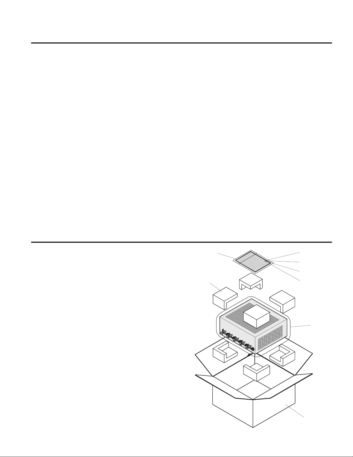
PA5800 PACKING EXPLODED VIEW
Ref.# Part # Discription Qty
40 150-0089-0 BAG POLY 24”x30”x3 mil with vent holes 1
41 150-0103-0 BAG POLY 9”x12”x2 mil CLEAR 1
42 HA160-0000-A OWNER’S MANUAL 1
43 HA160-0001-A WARRANTY SHEET 1
44 HA160-0002-A CUSTOMER CARD 1
45 160-0005-0 GROUNDING SAFETY SHEET 1
46 HA151-0001-A FOAM PACK CORNERS 8
47 HA150-0000-A CARTON 1
(4 TOP/4BOTTOM 8 PER SET)
46
41
42
43
44
45
40
47
9
Page 11

Multichannel Power Amplifier Harman Kardon PA5800 / SIGNATURE 2.1
Signature 2.1 MECHANICAL EXPLODED VIEW
7
QTY
4
5
18
43
4
30
3
8
A
QTY
5
27
4
93
12
2
DESCRIPTION & PART NO.
BOLT 4-40 5/16 PHP CAP
111-D051-0
BOLT 4-40 5/8 PHP CAD
111-0101-0
SCREW 4AB 1/2 PHP B.Z.
111-3080-0
TR-BOLT 4-40 3/8 PHP CAD
111-808101
111-8051-0
BOLT 6-32 1/4 PHP, ZINC
TR-BOLT 4-40 1/2 PHP CAD
112-004D-D
1
REF. NO.
HA132-0009-A
2
3
4
5
6
D
HA132-0013-B
HA132-0016-0
D
B
105-0009-0
C
D
2
9
HA206-0002-B
DESCRIPTION & PART NO.
REF. NO.
112-3080-0
7
B
TR-BOLT 6-32 5/16 PHP 80
112-8050-0
8
WASHER #4 SPILT
111-7011-0
WASHER #6 SPILTZINC
112-7021-0
STRAIN RELIEF, 16/2, SPT-2,UL,CSA
100-0035-0
POWER CORD, 2x18-16 GA,SPT-2,UL,CSA
095-0002-0
9
11
10
9
12
4
9
5
G
C
9
4
E
2
9
H
HA132-0014-B
8
D
H
G
E
HA206-0003-B
B
2
9
I
G
E
G
K
B
H
F
204-0001-0
K
R
I
J
A
E
HA132-0012-B
8
8
8
J
8
G
H
8
1
F
8
8
HA132-0015-B
B
1
9
M
8
M
HA132-0010-B
HA132-0021-A
125
128
M
H
H
G
8
8
10
Page 12

Multichannel Power Amplifier Harman Kardon PA5800 / SIGNATURE 2.1
Signature 2.1 MECHANICAL PARTS LIST
Ref.# Part # Discription Qty
A080-0010-A TRANSFORMER SIG 2.1, 120V TO SP 1
A080-0011-A TRANSFORMER SIG 2.1, 230V 1
A091-0007-0 FUSE, 5MM, 0.5A, 125V, FAST, UL, CSA 1
A091-0008-0 FUSE, 5MM, 5A, 125V, FAST, UL, CSA 10
A091-0011-0 FUSE, 5MM, 10A, 125V, FAST, UL, CSA 1
A092-0061-0 FASTON, F, V, .250X.032X.260, 14-16GA 1
A092-0068-0 FASTON, F, V, .187X.020X.205, 14-16GA 1
A093-2500-0 HSG, 2MMX7, 26GA, IDC 2
A095-1002-0 WIRE 26 AWG, BLK, 7 STRAND, UL1061 1 1
A095-0002-0 POWER CORD 16 GAUGE 1
100-0011-0 STRAIN RELIEF, SPT-2, UL, CSA 1
100-0035-0 CABLE TIE, BLACK, 4"-18 LB 10
100-0126-0 HOLDER, CABLE TIE .75" SQUARE, ADHE 5
101-0002-0 FOOT BLACK ANODIZED/RUBBER GASKET 4
102-0003-0 BUTTON CAP, LOUDNESS, H/K 1
105-0009-0 INSULATOR TAPE, 3/4"X7 MIL ADHESIVE 4
111-0051-0 BOLT, 4-40, 5/16, PHP, CAD 2
111-0061-0 BOLT, 4-40, 3/8, PHP, CAD 2
111-0101-0 BOLT, 4-40, 5/8, PHP, CAD. 18
111-3080-0 SCREW, 4AB, 1/2, PHP, B.Z. 5
111-7011-0 WASHER, #4, SPLIT 93
111-8061-0 TR-BOLT, 4-40, 3/8, PHP, CAD 43
111-8081-0 TR-BOLT, 4-40, 1/2, PHP, CAD 30
112-0040-0 BOLT, 6-32, 1/4, PHP, ZINC 4
112-3080-0 SCREW, 6AB, 1/2, PHP, B.Z. 5
112-7001-0 WASHER, #6, FLAT, CAD 4
112-7021-0 WASHER, #6, SPLIT ZINC 4
112-8050-0 TR-BOLT, 6-32, 5/16, PHP, BO 27
Ref.# Part # Discription Qty
153-0100-1 SAFETY LABEL(RISK OF FIRE), FAST F 1
HA132-0009-A SIG 2.1, FIN PLATE 28
120-0002-1 ALUM .080, 5052-H32, 6.00X5.15 +/- 1
HA132-0010-A SIG 2.1 FRONT PANEL, FINISHED 1
HA132-0012-B SIG 2.1 CHASSIS 1
111-6036-0 NUT, PEM, S-440-1 FOR .040 MIN. THK 4
112-6009-0 STANDOFF, SO-6440-24 14
120-0019-0 STEEL, 18 GA.EGC .047 48X120 FPR 480
HA132-0013-B SIG 2.1 REAR PANEL, 120V 1
120-0019-0 STEEL, 18 GA.EGC .047 48X120 FPR 198
HA132-0014-B SIG 2.1 TOP COVER 1
120-0012-0 STEEL, 20 GA.036 EGC 48X120 615
HA132-0015-B SIG 2.1 CROSS BRACE 1
120-0008-0 STEEL, 16 GA.EGC. 48X120 198
HA132-0016-B SIG 2.1 SINK PLATE 1
129-0003-A PA5800 SINK PLATE BLANK 16.7000" 1
HA132-0021-A LOGO, SIGNATURE SERIES, ACRYLIC 1
HA202-0003-A WIRE ASSY, 26GA, BLK, 9", 2PIN, UL/CSA 1
A093-1000-0 HSG, 2MMX2, 26GA, IDC 2
A095-1002-0 WIRE 26 AWG, BLK, 7 STRAND, UL1061 1 1
HA202-0004-A WIRE ASSY, 26GA, BLK, 7", 7PIN, UL/CSA 1
A093-2500-0 HSG, 2MMX7, 26GA, IDC 2
A095-1002-0 WIRE 26 AWG, BLK, 7 STRAND, UL1061 1 1
HA202-0005-A WIRE ASSY, 26GA, BLK, 18.5", 5PIN, UL/ 1
A093-1003-0 HSG, 2MMX5, 26GA, IDC 2
A095-1002-0 WIRE 26 AWG, BLK, 7 STRAND, UL1061 1 1
HA206-0002-B SIG 2.1 POWER AMP BOARD, 120V 1
51
55
Signature 2.1 PACKING EXPLODED VIEW
56
52
53
54
57
Ref.# Part # Discription Qty
50 HA150-0001-A SIG 2.1 CARTON 1
51 HA151-0002-A SIG 2.1/1.5 FOAM PACK 1
52 HA160-0001-A HARMAN WARRANTY SHEET 1
53 HA160-0002-A HARMAN CUSTOMER CARD 1
54 HA160-0003-A SIG 2.1 OWNER’S MANUAL 1
55 150-0089-0 BAG POLY 24X30 3 MIL WITH VENT HO 1
56 150-0103-0 BAG, PLOY 9"X12"X2MIL CLEAR 1
57 160-0005-0 GROUNDING SAFETY SHEET 1
51
50
11
Page 13

Multichannel Power Amplifier Harman Kardon PA5800 / SIGNATURE 2.1
PA5800 ELECTRICAL PARTS LIST
Reference # Part # Description Quantity
Power Switch/Remote Trigger Board
Integrated Circuit
U254 A001-2009-0 LM556CN DUAL TIMER 1
Transistors
Q218, 225, 226, A010-0012-0 MPSA06 NPN 80V 500MA TO-92 6
240, 245, 251
Q232, 234 A010-1013-0 MPSA56 PNP 80V 500MA TO-92 2
Diodes
D212, 213, 214, A020-2106-0 1N4004, RECT, 1A, 150V, DO-41 4
215
D217, 231, 236, A020-1000-0 1N4148, RECT-FAST, 200MA, 100V, 7
238, 241, 243, 4NS, DO-35
264
D260 A020-0050-0 1N751, ZENER, 5V 10%, 400MW, DO-35 1
D270 A025-0012-0 LED, RED/GRN, 5MM, 630NM/560NM, 1
15MCD/15MCD
Capacitors
C204 A034-7103-0 CAP, CERAMIC DISK, .01mF, 10%, X-250V 1
C210, 220, 224, A031-0108-0 CAP, ELEC, RAD, 100mF, -10%+50%, 16V 6
228, 259, 261
C211, 216, 244, A030-2104-0 CAP, CER, AX, .1mF, 10%, 50V, X7R 5
257, 262
C247, 249 A031-2106-0 CAP, ELEC, RAD, 10mF, -10%+50%, 50V 2
C253, 255 A030-2103-0 CAP, CER, AX, .01mF, 10%, 50V,X7R 2
C266 A031-0477-0 CAP, ELEC, RAD, 470mF, 20%, 10V 1
Resistors
R222, 223, 233, A050-1003-0 RES CARBON FILM, 10KW, 1/8W, 5% 7
235, 239, 281,
282
R227 A050-1002-0 RES, CARBON FILM, 1KW, 1/8W, 5% 1
R229, 248 A051-2701-0 RES, CARBON FILM, 270W, 1/4W, 5% 2
R230, 246, 256 A050-1004-0 RES, CARBON FILM, 100KW, 1/8W, 5% 3
R242 A050-3302-0 RES, CARBON FILM, 3.3KW, 1/8W, 5% 1
R250 A050-4702-0 RES, CARBON FILM, 4.7KW, 1/8W, 5% 1
R252 A050-4703-0 RES, CARBON FILM, 47KW, 1/8W, 5% 1
R258 A051-4703-0 RES, CARBON FILM, 47KW, 1/4W, 5% 1
R263, 265 A050-2205-0 RES CARBON FILM, 2.2MW, 1/8W, 5% 2
R283 A050-1001-0 RES, CARBON FILM, 100W, 1/8W/ 5% 1
Miscellaneous
T209 A080-0006-A TRANSFORMER STANDBY, 1
K206 A084-0002-0 RELAY, 12VDC, 1A, 15AMP/125VAC, 1
S219 A090-007-0 SWITCH, 8A/128A, 250V, PP, PCB 1
F203 A091-0023-0 FUSE, 1/4, 10A, 250V, FAST, 1
F208 A091-0000-0 FUSE, 5 x 20mm, .5A, 250V, SLO BLO 1
HA206-0001-B Loaded PA5800 Power Switch Board 1
120/10@.09A, PCB
TV-8, PCB
CERAMIC ACG
Reference # Part # Description Quantity
J284 A092-0019-0 JACK, PHONE, 3.5MM, S-TIP, 1
P221 A093-0043-0 HDR, 2MMX3, VERT, MALE LOCK 1
P237 A093-0151-0 HDR, 2MMX5, VERT, MALE, LOCKING 1
P260 A093-0026-0 HDR, .1X3, HORIZ, MALE, 1
P271 A093-0526-0 HDR, .1X3. BOTTOM ENTRY, 1
P280 A093-0044-0 HDR, 2MMX3, HORIZ, MALE LOCK 1
FUSE CLIP A094-0004-0 FUSE CLIP, 5MM, PC MOUNT 2
FUSE CLIP A094-0015-0 FUSE CLIP, PC MOUNT, .250, 15A 2
O-SLEV, VERT PC
SQUARE PIN, TIN
093-0026 MATE
POWER AMP BOARD
Transistors
Q14A, 14B, 14C, A010-0010-0 2SC2240, NPN, 120V, 100MA, TO-92 10
14D, 14E, 18A,
18B, 18C, 18D,
18E
Q23A, 23B, 23C, A010-0012-0 MPSA06, NPN, 80V, 500MA, TO-92 10
23D, 23E, 24A,
24B, 24C, 24D,
24E
Q30A, 30B, 30C, A010-1010-0 2SA970, PNP, 120V, 100MA, TO-92 10
30D, 30E, 37A,
37B, 37C, 37D,
37E
Q46A, 46B, 46C, A010-0001-0 2SC3478, NPN, 180V, 100MA 15
46D, 46E, 64A,
64B, 64C, 64D,
64E, 79A, 79B,
79C, 79D, 79E
Q69A, 69B, 69C, A010-1002-0 2SA1376, PNP, 180V, 100MA, TO-92 10
69D, 69E, 82A,
82B, 82C, 82D,
82E
Q88A, 88B, 88C, A012-0002-0 2SC4793, NPN, 200V, 1.5A, 2-10R1A 10
88D, 88E, 89A,
89B, 89C, 89D,
89E
Q91A, 91B, 91C, A012-1002-0 2SA1837, PNP, 200V, 1.5A, 2-110R1A 5
91D, 91E
Q98A, 98B, 98C, A012-0003-0 2SC5242, NPN, 230V, 15A, 2-16C1A 10
98D, 98E, 99A,
99B, 99C, 99D,
99E
Q100A, 100B, A012-1003-0 2SA1962, PNP, 230V, 15A, 2-16C1A 10
100C, 100D,
100E, 101A,
101B, 101C,
101D, 101E
Q121 A010-1013-0 MPSA56, PNP, 80V, 500MA, TO-92 1
Diodes
D31A-E, D33A-E, A020-1000-0 1N4148, REST-FAST, 200MA, 25
D41A-E, 100V, 4NS, DO-35
D80A-E,
D81A-E
D90A, 90B, 90C, A020-2106-0 1N4004, RECT, 1A, 150V, DO-41 10
90D, 90E, 92A,
92B, 92C, 92D,
92E
BR53A, 53B, 53C, A023-0004-0 BRIDGE, 8A, 200V, VERT, PC 5
53D, 53E
12
Page 14

Multichannel Power Amplifier Harman Kardon PA5800 / SIGNATURE 2.1
Reference # Part # Description Quantity
Capacitors
C6A-E, C7A-E, A030-2271-0 CAP, CER AXIAL, 2700pf, 10%, 50V, NPO 15
C12A-E
C9A, 9B, 9C, 9D, A032-4104-0 CAP, PE, .1mF, 10%, 100V 15
9E
C17A-E, C49A-E, A031-3476-0 CAP, ELEC, RAD, 47mF, 20%, 63V 15
C50A-E
C22A-E A031-0477-0 CAP, ELEC, RAD, 470mF, 20%, 10V 5
C26A, 26B, 26C, A031-2828-0 CAP, ELEC, RAD, 8200mF, 20%, 50V 10
26D, 26E, 27A,
27B, 27C, 27D,
27E
C32A, 34B, 34C, A030-2102-0 CAP, CER, AX, .001mF, 10%, 50V, X7R 10
34D, 34E, 38A,
38B, 38C, 38D,
38E
C44A, 44B, 44C, A031-2106-0 CAP, ELEC, RAD, 10mF, -10%+50%, 50V 10
44D, 44E, 71A,
71B, 71C, 71D,
71E
C45A-E A035-8150-0 CAP, MICA, 15PF, 5%, 500V 5
C51A, 51B, 51C, A030-4104-0 CAP, CER AXIAL, 2700pf, 10%, 100V, X7R 10
51D, 51E, 52A,
52B, 52C, 52D,
52E
C56A-E, C57A-E, A030-2104-0 CAP, CER, AX, .1mF, 10%, 50V, X7R 11
124
C67A-E A035-8131-0 CAP, MICA, 130PF, 5%, 500V 5
Resistors
R2A-E A050-1004-0 RES, CARBON FILM, 100KW, 1/8W, 5% 5
R3A-E A060-1242-0 RES, METAL FILM, 1.24K, 1/8W, 1% 5
R8A, 8B, 8C, 8D, A055-0510-0 RES, METAL OXIDE, 5.1W, 2W, 5% 5
8E
R10A, 10B, 10C, A055-0101-0 RES, METAL OXIDE, 10W, 2W, 5% 5
10D, 10E
R11A, 11B, 11C, A050-3303-0 RES, CARBON FILM, 33KW, 1/8W, 5% 7
11D, 11E, 43D,
43E
R13A-E, R16A-E, A050-1002-0 RES, CARBON FILM, 1KW, 1/8W, 5% 20
R20A-E, R72A-E
R21A-E A050-1801-0 RES, CARBON FILM, 180W, 1/8W, 5% 5
R28A-E, R35A-E, A050-4701-0 RES, CARBON FILM, 470W, 1/8W, 5% 20
68A-E, 77A-E
R29A-E, R15A-E, A050-1001-0 RES, CARBON FILM, 100W, 1/8W, 5% 35
R19A-E, R36A-E,
R63A-E, R76A-E,
R95A-E
R32A, 32B, 32C, A050-5602-0 RES, CARBON FILM, 5.6KW, 1/8W, 5% 15
32D, 32E, 73A,
73B, 73C, 73D,
73E, 74A, 74B,
74C, 74D, 74E
R42A, 42B, 42C, A050-3302-0 RES, CARBON FILM, 33KW, 1/8W, 55 6
42D, 42E, 120
R43A-E A060-3323-0 RES, METAL FILM, 33.2KW, 1/8W, 1% 5
R48A, 48B, 48C, A055-6802-0 RES, METAL OXIDE, 6.8K, 2W, 5% 10
48D, 48E, 85A,
85B, 85C, 85D,
85E
Reference # Part # Description Quantity
R54A, 54B, 54C, A050-0101-0 RES, CARBON FILM, 10W, 1/8W, 5% 20
54D, 54E, 55A,
55B, 55C, 55D,
55E, 93A, 93B,
93C, 93D, 93E,
96A, 96B, 96C,
96D, 96E
R60A, 60B, 60C, A056-330-1 RES, WIRE WOUND, .33W, 3W, 5% 20
60D, 60E, 61A,
61B, 61C, 61D,
61E, 83A, 83B,
83C, 83D, 83E,
84A, 84B, 84C,
84D, 84E
R62A-E, R66A-E A050-2203-0 RES, CARBON FILM , 22KW, 1/8W, 5% 10
R65A-E A050-2202-0 RES, CARBON FILM, 2.2KW, 1/8W, 5% 5
R70A, 70B, 70C, A070-0520-0 POT, 500W TRIM, .375 ROUND, 5
70D, 70E SLOT, .5W
R78A-E A050-1202-0 RES, CARBON FILM, 1.2KW, 1/8W, 5% 5
R87A-E, R102A-E, A050-4703-0 RES, CARBON FILM, 47KW, 1/8W, 5% 11
D122
Miscellaneous
L94A, 94B, 94C, A081-0057-0 INDUCTOR, 2UH, 7A, 2743002112 10
94D, 94E, 97A, FERRITE BEAD
97B, 97C, 97D,
97E
FUSE A091-0019-0 FUSE, 5MM, 5A, 250V, SLB, UL, SEMKO 10
FUSE CLIP A094-0004-0 FUSE CLIP, 5MM, PC MOUNT 10
TH127 A091-1002-0 THRM BRKR 105C +/-5, 0-DIFF, PC 1
A091-1003-0 THRM BRKR 100C +/-5, 0-DIFF, PC 1
J5A, 5B, 5C, 5D, A092-0018-0 BINDING POST, X2, H, PC, NI 5
5E
J1A, 1B, 1C, 1D, A092-0031-0 JACK, RCAX1, H, PC, GOLD, WT 5
1E
P75A, 75B, 75C, A093-0025-0 HDR, .1X2, VERT, MALE, LOCK, GOLD 5
75D, 75E
P86A, 86B, 86C, A093-0080-0 HDR, .156X3, VERT, MALE, LOCK, 5
86D, 86E SQR PINS, TIN
P123 A093-0151-0 HDR, 2MMX5, VERT, MALE, LOCKING 1
RL47A, 47B, 47C, A081-0032-0 INDUCTOR .4 UH WITH 1W 2W RESISTOR 5
47D, 47E
HA206-000-C LOADED PA5800 AMPLIFIER BOARD 1
13
Page 15

Multichannel Power Amplifier Harman Kardon PA5800 / SIGNATURE 2.1
Signature 2.1 ELECTRICAL PARTS LIST
Reference # Part # Description Quantity
Power Amplifier Board
Transistors
Q1, 14, 33, 55, A010-1013-0 MPSA56 PNP 80V 500MA TO-92 6
77, 99
Q2, 16, 17, 29, A010-0001-0 2SC3478, NPN, 180V, 100MA 15
31, 32, 51,
53, 54, 73,
75, 76, 95,
97, 98
Q3, 5, 7, 37, A012-1003-0 2SA1962, PNP, 230V, 15A, 2-16C1A 15
38, 39, 59,
60, 61, 81,
82, 83, 103,
104, 105
Q4, 6, 8, 40, A012-0003-0 2SC5242, NPN, 230V, 15A, 2-16C1A 15
41, 42, 62,
63, 64, 84,
85, 86, 106,
107, 108
Q10, 11, 24, 25, A012-0002-0 2SC4793 NPN 200V 1.5A 2-10R1A 10
46, 47, 68, 69,
90, 91
Q12, 18, 19, 34, A010-1002-0 2SA1376, PNP, 180V, 100MA, TO-92 15
35, 36, 56, 57,
58, 78, 79, 80,
100, 101, 102
Q15, 43, 65, A010-1003-0 2SA1380-F, PNP, 200V, 100MA, TO-126 5
87, 109
Q13, 44, 66, A010-0003-0 2SC3502-F, NPN, 200V, 100MA, TO-126 5
88, 110
Q20, 23, 27, 28, A010-0012-0 MPSA06 NPN 80V 500MA TO-92 10
49, 50, 71, 72,
93, 94
Q21, 22, 30, 45, A010-0010-0 2SC2240, NPN, 120V, 100MA, TO-92 10
52, 67, 74, 89,
96, 111
Diodes
D1, 4, 5, 6, 7, A020-1000-0 1N4148, RECT-FAST, 200MA, 100V, 4NS 25
10, 11, 12,
13, 14, 17,
18, 19, 20,
21, 24, 25,
26, 27, 28,
31, 32, 33,
34, 35
D2, 3, 8, 9, A020-2106-0 1N4004, RECT, 1A, 150V, DO-41 10
15, 16, 22,
23, 29, 30
BR1, 2, 3, 4, 5 A023-0004-0 BRIDGE, 8A, 200V, VERT, PC 5
A025-0012-0 LED, RED/, 5MM, 630NM/560NM, 15MCD 1
Capacitors
C1 A030-2104-0 CAP, CER, AX, .1mF, 10%, 50V, X7R 1
C2, 3, 30, 31, A031-3129-0 CAP, ELEC, RAD, 12000mF, 20%, 63V 10
51, 52, 72,
73, 93, 94
C4, 6, 7, 8, 40, A030-4104-0 CAP, CER AXIAL, .1mF, 10%, 100V, X7R 20
41, 42, 43, 61,
62, 63, 64, 82,
83, 84, 85, 103,
104, 105, 106
C5, 10, 32, 33, A031-2106-0 CAP, ELEC, RAD, 10mF, -10%+50%, 50V 10
53, 54, 74,
75, 95, 96
Reference # Part # Description Quantity
C9, 27, 48, A035-8271-0 CAP, PE/MICA, 2700pf, 5%, 100/500V 5
69, 90
C11, 15, 24, 26 A031-3476-0 CAP, ELEC, RAD, 47mF, 20%, 63V 10
45, 47, 66, 68,
87, 89
C12, 28, 49, A035-8100-0 CAP, MICA, 10pf, 5%, 500V 5
70, 91
C13, 14, 34, 37, A030-2102-0 CAP, CER, AX, .001mF, 10%, 50V, X7R 10
55, 56, 76,
79, 97, 100
C16, 17, 23, 25, A031-0477-0 CAP, ELEC, RAD, 470mF, 20%, 10V 10
44, 46, 65,
67, 86, 88
C18, 29, 50, A032-4104-0 CAP, PE, .1mF, 10%, 100V 5
71, 92
C19, 20, 21, A030-2271-0 CAP, CER AXIAL, 2700pf, 10%, 50V, NPO 15
35, 36, 38,
56, 57, 59,
77, 78, 80,
98, 99, 101
Resistors
R1, 10, 18, 20 A050-1001-0 RES, CARBON FILM, 100 OHM, 1/8W, 5% 31
21, 44, 47, 71,
72, 76, 77, 78,
79, 119, 120,
124, 125, 126,
127, 167, 168,
172, 173, 174,
175, 215, 216,
220, 221, 222,
223
R2, 3, 11, 24, 28 A050-1003-0 RES, CARBON FILM, 10K OHM, 1/8W, 5% 17
67, 68, 74, 115,
116, 122, 163,
164, 170, 211,
212, 218
R4 A050-3302-0 RES, CARBON FILM, 3.3K OHM, 1/8W, 5% 1
R5, 7, 12, 43, A050-4703-0 RES, CARBON FILM, 47K OHM, 1/8W, 5% 16
61, 62, 73,
109, 110, 121,
157, 158, 169,
205, 206, 217
R6, 99, 147, A055-0101-0 RES, METAL OXIDE, 10 OHM, 2W, 5% 5
195, 243
R8, 9, 100, 101 A055-6802-0 RES, METAL OXIDE, 6.8K, 2W, 5% 10
148, 149, 196,
197, 244, 245
R13, 14, 15, A054-.220-0 RES, WIRE WOUND, .22 OHM, 1W, %5 30
16, 17, 18,
54, 56, 57,
58, 59, 60,
102, 104, 105,
106, 107, 108,
150, 152, 153,
154, 155, 156,
198, 200, 201,
202, 203, 204
R23, 27, 45, 48, A050-1002-0 RES, CARBON FILM, 1K OHM, 1/8W, 5% 25
50, 64, 83, 84,
85, 86, 112, 131,
132, 133, 134,
160, 179, 180,
181, 182, 208,
227, 228, 229,
230
R25, 89, 137, A050-7500-0 RES, CARBON FILM, 75 OHM, 1/8W, 5% 5
185, 233
14
Page 16

Multichannel Power Amplifier Harman Kardon PA5800 / SIGNATURE 2.1
Reference # Part # Description Quantity
R26, 75, 123, A050-5602-0 RES, CARBON FILM, 5.6K OHM, 1/8W, 5% 5
171, 219
R29, 38, 65, 66, A050-0471-0 RES, CARBON FILM, 47 OHM, 1/8W, 5% 10
113, 114, 161,
162, 209, 210
R30, 63, 111, A050-1202-0 RES, CARBON FILM, 1.2K OHM, 1/8, 5% 5
159, 207
R31, 32, 33, 34, A050-4701-0 RES, CARBON FILM, 470 OHM, 1/8W, 5% 30
35, 36, 90, 91,
92, 93, 94, 95,
138, 139, 140,
141, 142, 143,
186, 187, 188,
189, 190, 191,
234, 235, 236,
237, 238, 239
R37, 41, 69, 70, A050-0101-0 RES, CARBON FILM, 10 OHM, 1/8W, 5% 10
117, 118, 165,
166, 213, 214
R39, 98, 146, A055-0510-0 RES, METAL OXIDE, 5.1 OHM, 2W, 5% 5
194, 242
R40, 51, 87, A060-3323-0 RES, METAL FILM, 33.2K OHM, 1/8W, 1% 10
88, 135, 136,
183, 184, 231,
232
R42, 46, 49, A050-1801-0 RES, CARBON FILM, 180 OHM, 1/8, 5% 15
80, 81, 82,
128, 129, 130,
176, 177, 178,
224, 225, 226
R52, 96, 144, A060-1072-0 RES, METAL FILM, 1.07K OHM, 1/8W, 1% 5
192, 240
R53, 97, 145, A050-1004-0 RES, CARBON FILM, 100K OHM, 1/8W, 5% 5
193, 241
R22, 55, 193, A070-0520-0 POT, 500 OHM TRIM, .375 ROUND, SLOT, 5
151, 199
Miscellaneous
F1-10 A091-0008-0 5A Fast-blo GMA 5 x 20mm Fuse 10
TH1 A091-1003-0 BRKR 100C +/-5, 0-DIFF, PC 1
J2, 5, 7, 9, 11 A092-0012-0 BINDING POST, X2, H, PC, GOLD, GALLIEN 5
J3, 4, 6, 8, 10 A092-0032-0 JACK, RCAX1, H, GOLD, WT, SWITCH T/S 5
P2, 4, 6, 8, 10 A093-0025-0 HDR, .1X2, VERT, MALE, LOCK, GOLD 5
P1, 5, 7, 9, 11 A093-0080-0 HDR, .156X3, VERT, MALE, LOCK, SQR PIN 5
RL1, 2, 3, 4, 5 A081-0032-0 INDUCTOR, .4 UH WITH 1 OHM 2W RESI 5
L1, 2, 3, 4, 5, A081-0057-0 INDUCTOR, 2UH, 7A, 2743002112 FERRIT 10
6, 7, 8, 9, 10
A093-2005-0 HDR, 2MMX7, VERT, SHROUDED 1
A094-0004-0 FUSE CLIP, 5MM, P.C. MOUNT 10
105-0007-0 INSULATOR TUBE 1
153-0105-0 LABEL, BLANK, .9"X.25" 1
HA206-0002-B LOADED 2.1 AMPLIFIER BOARD 1
Power Switch/Indicator Board
Reference # Part # Description Quantity
Integrated Circuits
U1 A001-0005-0 LM393N, DUAL , 8 PIN DI, COMPARATOR 1
U2 A001-2009-0 LM556CN DUAL TIMER 1
Transistors
Q2, 3, 4, 7, 8 A010-0012-0 MPSA06 NPN 80V 500MA TO-92 5
Q1, 5, 6 A010-1013-0 MPSA56 80V 500MA TO-92 3
Diodes
D1, 2, 3, 4, 7 A020-2106-0 1N4004, RECT, 1A, 150V, DO-41 5
D5, 6, 8, 9, 10, A020-1000-0 1N4148, RECT-FAST, 200MA, 100V, 4NS, 12
11, 12, 13, 14,
15, 16, 27
D17, 18, 19, A025-0030-0 LED, BLUE, T1, .190, 470NM, SMALL 9
20, 21, 22,
23, 24, 25
D26 A025-0012-0 LED, RED/, 5MM, 630NM/560NM, 15MCD 1
D28 A020-0004-0 1N755A, 7.5V, 500MW, DO-35, ZENER 1
Capacitors
C1 A034-7103-0 CAP, CERAMIC DISK, .01mF, 10%, X-250V 1
C2, 3, 5, 9, 11 A030-2104-0 CAP, CER, AX, .1mF, 10%, 50V, X7R 5
C4 A031-0108-0 CAP, , RAD, 1000mF, -10%+50%, 16V 1
C6, 7, 8, 12 A031-0107-0 CAP, ELEC, RAD,100mF,+/-20%,16V,LOW L 4
C10 A031-0106-1 CAP, , RAD, 10mF, 20%, 25V, NP 1
C13, 14 A030-2103-0 CAP, CER, AX, .01mF, 10%, 50V, X7R 2
Resistor
R1, 2, 5, 9, 10, A050-1003-0 RES, CARBON FILM, 10K OHM, 1/8W, 5% 9
15, 18, 20, 22
R3, 4, 6, 19 A050-1004-0 RES, CARBON FILM, 100K OHM, 1/8W, 5% 4
R8, 13 A050-4703-0 RES, CARBON FILM, 47K OHM, 1/8W, 5% 2
R11, 12 A050-4702-0 RES, CARBON FILM, 4.7K OHM, 1/8W, 5% 2
R14 A050-0750-0 RES, CARBON FILM, 7.5 OHM, 1/8W, 5% 1
R16 A051-2202-0 RES, CARBON FILM, 2.2K OHM, 1/4W, 5% 1
R17 A051-1502-0 RES, CARBON FILM, 1.5K OHM, 1/4W, 5% 1
R21 A050-1005-0 RES, CARBON FILM, 1M OHM, 1/8W, 5% 1
Miscellaneous
F1 A091-0011-0 10A Fast-blo GMA 5 x 20mm FUSE 1
F2 A091-0007-0 .5A Slo-blo GMA 5 x 20mm FUSE 1
A080-0002-A TRANSFORMER STANDBY, 120V 10V@.35A 1
J1 A092-0022-0 JACK, PHONE, 3.5MM, H, PC 1
K1, 2 A084-0001-0 RELAY 12VDC, 20A/125VAC, TV-10 2
P1, 3, 4 A092-0010-0 FASTON, M, PC, .25" 3
P2 A092-0024-0 FASTON, M, PC, .187" 1
P5, 6 A093-0051-0 , 2MMX2, VERT, MALE, LOCK 2
S2 A093-0151-0 , 2MMX5, VERT, MALE, LOCKING 1
S1 A093-2005-0 , 2MMX7, VERT, SHROUDED 1
S3 A090-0007-0 SWITCH, 8A/128A, 250V, PP, PCB 1
S4 A093-0049-0 , 2MMX5, HORIZ, MALE, LOCK 1
A094-0004-0 FUSE CLIP, 5MM, P.C. MOUNT 4
A022-3001-0 THERMISTOR, 120 OHM, 2AMP, CL-90 1
HA206-0003-B LOADED SIG 2.1 POWER SWITCH BOARD 1
15
Page 17

Multichannel Power Amplifier Harman Kardon PA5800 / SIGNATURE 2.1
PA5800 POWER SWITCH PCB
PA5800 POWER SWITCH/
INDICATOR BOARD
HA145-0001-B6
16
Page 18

17
PA5800 POWER AMPLIFIER PCB
Power Amplifier Preliminary Service Manual Harman Kardon PA5800/SIGNATURE 2.1
Page 19

Multichannel Power Amplifier Harman Kardon PA5800 / SIGNATURE 2.1
Signature 2.1 POWER SWITCH/INDICATOR PCB Rev B9 & D
P1
/
UL CSA:
EUROPE:
F1
K1
HARMAN
HA206-0003-B9
D5
D6
Q1
C
B
E
C
B
E
D13
D12
P5
R4
+
R9
Q4
GALLIEN TECH
HA145-0003-B9
10A 125V
5A 250V
R1
R22
R21
C7
D27
R11
R10
R14
D15
F2
D7
Q5
P2
R20
Q7
D16
R2
K2
D8
U1
C
B
E
C1
0.5A 250V
D9
D10
S2
Q8
C
B
E
R15
P
D11
T1
TH1
C5
R6
Q6
C
B
E
R3
D28
R16
Q2
E
R17
P3
BRN
RED
B
C
S1
C6
+
+
C
B
E
D14
R12
R18
C13
P4
BLUE
D2
D3
D1
C2
R5
C9
C10
C8
+
R13
U2
RED
S
D4
+
C
B
Q3
E
C3
+
R19
R8
C4
C11
C12
C14
P6
D21
S3
D25
D22 D23 D24
D19 D20D18
D17
S4
D26
SIG 2.1 POWER SWITCH/
INDICATOR BOARD
REV. B9
HA405-0003-B9
P1
/
UL CSA:
EUROPE:
F1
K1
HARMAN
HA206-0003-C
D5
D6
Q1
C
B
E
C
B
Q4
GALLIEN TECH
P5
C7
E
D12
D13
+
R4
R9
HA145-0003-C
10A 125V
5A 250V
0.5A 250V
D7
R1
R22
R21
D27
R11
R10
D15
R14
P2
R20
Q5
D16
R2
Q7
D8
P3
BRN
T1
P
C1
K2
D10
D11
D9
U1
S2
C
B
E
C
B
Q8
E
R15
F2
TH1
C5
R6
C
B
E
R3
D28
Q6
R16
Q2
E
R17
RED
B
C
S1
C6
+
C8
+
C
B
E
D14
R12
R18
C13
P4
BLUE
D1
D3D2D4
C2
Q3
R5
C9
C10
R13
U2
RED
S
C3
+
C
B
E
C12
+
R19
R8
C4
C11
C14
P6
D21
S3
D25
D24
D23
D22
D20
D19
D18
D17
S4
D26
SIG 2.1 POWER SWITCH/
INDICATOR BOARD
REV. D
HA145-0003-D
18
Page 20

19
Signature 2.1 POWER AMPLIFIER PCB
P3
Q1
R5
C1
CBE
R4
C94
C96
++
R217
D31
E
C
B
Q97
R245
P11
Q108
Q106
C103
D30
R206
R218
R220
D29
R201
R204
R200
R203
F10
F9
5A
BR5
P10
C93
5A 125V
+
C105
R244
R169
D24
E
C
B
Q104
Q86
Q103
Q84
C73
R243
+
+
C75
Q75
R197
P9
C82
D23
C61
R158
R170
R172
D22
R153
R156
Q82
Q64
TH1
R152
R155
Q81
Q62
F8
R195
+
++
C54
F7
P7
5A
BR4
P8
C84
R196
R121
D17
E
C
B
Q53
R149
C72
5A 125V
+
+
D16
5A
P5
BR3
P6
C63
R148
R73
D10
E
C
B
Q31
R101
5A 125V
++
F6
F5
R147
+
+
C33
C31 C51 C52
R110
R122
R124
D15
R105
R108
Q60
Q42
R104
R107
Q59
Q40
C40
D9
R62
R74
R76
D8
R57
R60
Q38
Q4
R56
R59
Q37
Q6
5A 125V
F4
R99
C5
5A
BR2
F3
P4
C42
R100
R7
D1
E
+
C
B
Q2
P1
R9
C8
D3
C2 C3 C30
5A 125V
F1
R6
F2
5A
C6
BR1
P2
R8
R12
R11
R10
D2
R13
R14
Q3
R15
R16
Q5
R198
R150
R102
R54
R17
HA145-0002-B
GALLIEN TECHNOLOGY
Q107
Q91
Q90
R202
Q92
Q105
Q85
Q69
Q68
R154
Q70
Q83
Q63
Q47
Q46
R106
Q48
Q61
Q41
Q25
Q24
R58
Q26
Q39
Q8
Q11
Q10
R18
Q9
Q7
R223
L10
R175
L8
R127
L6
R79
L4
R19
L1
R216
R215
R168
R167
R120
R119
R72
R71
R21
R20
R1
HA206-0002-B
HARMAN
E
C
Q100
B
E
C
Q101
B
E
C
Q95
B
Q110
ECB
+
E
C
Q78
B
E
C
Q79
B
E
C
Q73
B
Q87
ECB
+
ECB
+-
+-
C104
C95
ECB
+-
Q88
C83
C74
C91
R210
R213
R242
R162
R165
R224
R228
C100
R221
R225
R229
R222
C97
R205
D32
R226
R214
R232
C89
R176
R180
C79
R173
R177
R181
R174
C76
R157
D25
R178
R166
C70
R184
C68
E
C
B
E
C
B
C106
E
C
B
E
C
B
C85
R194
+-
+-
E
B
Q93
C
+-
+- +-
+-
+-
E
B
Q71
C
+-
+-
R235
R237
D35
R236
D33
D34
L9
ECB
ECB
R238
R234
R239
R207
R209
R212
R208
R219
R233
R211
R230
TO92
C90
E
C
Q98
B
Q109
E
B
Q99
C
ECB
R199
E
C
Q102
B
R187
R189
D28
R188
D26
D27
L7
ECB
ECB
R190
R186
R191
R159
R161
R164
R160
R171
R185
R163
R182
C69
E
C
Q76
B
E
B
Q77
C
ECB
R151
E
C
B
Q80
R3
R2
C86
C88
C87
RL5
C65
E
B
C
C67
C66
RL4
Q111
Q96
E
B
C
R227
J11
C92
Q89
Q74
R179
J9
T
T
Q94
Q72
TTS
G
J1
J10
TST
G
C102
R241
R231
C99
R240
C101
REDBLKREDBLK REDBLK REDBLKREDBLK
C98
J8
TST
G
C81
R193
R183
C78
R192
C80
C77
C71
E
C
Q56
B
E
C
Q57
B
E
C
Q51
B
ECB
+
E
C
Q34
B
E
C
Q35
B
E
C
Q29
B
Q43
ECB
+
E
C
Q19
B
E
C
Q18
B
E
C
Q17
B
ECB
+
ECB
Q65
Q66
ECB
Q44
ECB
Q15
Q13
+-
+-
C62
C53
+-
C41
C32
+-
C7
C10
R66
R69
R38
R37
R114
R117
D18
C49
R136
C47
C37
D11
R70
C28
R88
C26
D7
C4
R41
C12
R40
C11
R128
R132
C58
R125
R129
R133
R126
C55
R109
C64
R118
R80
R84
R77
R81
R85
R78
C34
R61
R82
C43
R49
R48
C14
R47
R46
R45
R44
C13
R43
R42
R130
E
C
B
E
C
B
+-
E
B
Q49
C
+-
+- +-
+-
R146
E
C
B
E
C
B
+-
E
B
Q27
C
+-
+-
R98
E
C
B
E
C
B
+-
E
B
Q20
C
+-
+-
R39
Q67
Q52
C46
C45
RL3
C23
C25
C24
RL2
Q22
Q21
C16
C15
C44
R131
E
B
C
J7
Q45
Q30
R83
E
B
C
J5
C17
R50
E
B
C
RL1
T
T
T
Q23
TST
Q50
TST
Q28
TST
J6
J4
J3
G
C50
G
C29
G
C59
C56
R97
R87
C36
R96
C38
C35
R53
R51
C21
R52
C20
C19
C60
R145
R135
C57
R144
C39
C22
R139
R141
D21
R140
D19
D20
L5
ECB
ECB
R142
R138
R143
R111
R113
R116
R112
R123
R137
R115
R134
C48
E
C
Q54
B
E
B
Q55
C
ECB
R103
E
C
B
Q58
R91
R93
D14
R92
D12
D13
L3
R94
R90
R95
R63
R75
R89
R67
R86
C27
R65
R68
R64
E
C
Q32
B
E
B
Q33
C
ECB
ECB
ECB
R55
E
C
B
Q36
R36
R35
D6
R34
D5
D4
L2
R33
R32
R31
R30
C9
R26
R25
R24
R23
R29
R28
R27
E
C
Q16
B
E
B
Q14
C
ECB
ECB
ECB
R22
E
C
Q12
B
C18
Power Amplifier Preliminary Service Manual Harman Kardon PA5800/SIGNATURE 2.1
Page 21

Multichannel Power Amplifier Harman Kardon PA5800 / SIGNATURE 2.1
PA5800 (120V) TRANSFORMER WIRING REV B
A
B
C
D
1
2
PA5800 (120V)
Transformer Wiring
E
1
2
Rev B
3
3
4
5
6
7
4
5
6
7
A
B
C
D
E
20
Page 22

Multichannel Power Amplifier Harman Kardon PA5800 / SIGNATURE 2.1
Signature 2.1 (120V) TRANSFORMER WIRING
A
B
C
D
1
2
Signature 2.1 (120V)
E
1
2
Transformer Wiring
Rev 0
3
3
4
5
6
7
4
5
6
7
A
B
C
D
E
21
Page 23

Multichannel Power Amplifier Harman Kardon PA5800 / SIGNATURE 2.1
Signature 2.1 (230V) TRANSFORMER WIRING REV 0
A
B
C
D
1
2
3
E
1
2
3
4
5
4
5
Signature 2.1 (230V)
Transformer Wiring
Rev0
6
7
6
7
A
B
C
D
E
22
Page 24

Multichannel Power Amplifier Harman Kardon PA5800 / SIGNATURE 2.1
Signature 2.1 (230V) TRANSFORMER WIRING REV B
23
Page 25

Multichannel Power Amplifier Harman Kardon PA5800 / SIGNATURE 2.1
INTEGRATED CIRCUITS
Signature 2.1: U1
LM393N DUAL COMARATOR
A001-0005-0
OUTPUT A
INVERTING
INPUT A
NONINVERTING
INPUT A
GND
1
2
3
4
PA5800: U254
Signature 2.1: U2
LM556CN DUAL TIMER
A001-2009-0
CC
V
14 10
DISCHARGE
13 9
THRESHOLD
12 8
CONTROL
VOLTAGE
11
8
7
INVERTING
6
INPUT B
NONINVERTING
5
INPUT B
RESET
+V
S
OUTPUT B
OUTPUT
TRIGGER
COMP
COMP
15
26
37
FLIP FLOP
4
FLIP FLOP
COMP
COMP
GND
DISCHARGE
THRESHOLD
CONTROL
VOLTAGE
RESET
OUTPUT
TRIGGER
24
Page 26

Multichannel Power Amplifier Harman Kardon PA5800 / SIGNATURE 2.1
PA5800 POWER SWITCH SCHEMATIC (1 of 1)
G
F
E
D
C
B
A
1
C257
104
R258
1/4 W
47K
R239
10K
R256
100K
107
103
16V
C255
C259
R235
10K
R223
103
C12
C220
107
16V
25DX
3
2
1N4148
Q234
A56
4
MUTE
P237-3
+12V
K206
C261
107
5V
P205
1
D217
16V
D260
1
8
9
10
11
12
13
10K
Q226
10K
R222
100K
R230
D231
A06
RLY-SPST
PWRSW-IN
2
D1
LM556
TRG2
OUT2
RST2
CRT2
THR2
DIS2
U254
4.7K
R250
Q225
A06
1N4148
P221-3
2
TRG1
OUT1
RST1
CRT1
THR1
DIS1
GND
Q245
A06
Q240
A06
1/4 W
1/4 W
1N4148
6
5
4
3
2
1
1/4 W
R248
Q218
A06
P237-4
FAULT
R2
R1
+12V
R252
270
R227
1/4 W
27D
R229
P221-1
P280-1
2
R282
1
P280-3
T
J294
47K
47K
P237-1
C247
47K
Q5
A56
1K
10K
TS
S
C244
104
3.3K
R242
C1
104
C253
106
D270
10K
R281
16V
GRN
RED
16V
C262
104
P237-2
103
P260-3
P271-3
P271-1
P260-1
S219
R283
P260-2
COM
P271-2
POWER SWITCH
P1-1
R221-2
P280-2
1D0
3
1N4148
D243
DCSENSE
P237-5
3
104
C211
Q251
C224
107
PWRSW-IN
A06
C7
R245
100K
16V
D212
F208
2T09
F203
106
16V
D236
1N4148
1N4148
D241
10K
R233
+12V
3
1
P201
1N4148
D238
107
16V
C228
C210
1N4004
4
2
P202
105
16V
1N4004
D213
D215
1N4004
D214
1N4004
AMP_A.P86-1
3
T1
P207
C216
AMP_A.P86-2
AMP_B.P86-1
AMP_A.P86-3
5
4
6
4
GND
104
AMP_B.P86-2
AMP_B.P86-3
8
7
9
1
4
AMP_C.P86-2
AMP_C.P86-1
AMP_C.P86-3
11
10
12
2
TO_P207
TO_P205
PA5800
AMP_D.P86-3
AMP_D.P86-2
AMP_D.P86-1
AMP_E.P86-1
13
14
15
5
1of1
Power Switch Schematic
AMP_E.P86-3
AMP_E.P86-2
16
17
XFR-PA5800
5
G
F
E
D
C
B
A
25
Page 27

Multichannel Power Amplifier Harman Kardon PA5800 / SIGNATURE 2.1
PA5800 POWER AMPLIFIER SCHEMATIC
G
F
E
D
C
B
A
1
NOTE: top part of schematic is typical for all five power amps
and reference designators have suffixes A-E for respective channels
1
+50V
R55
D90
1N4004
2
J5
RED
C6
271
R2W
5.1
R8
FAULT
1N4148
D5
L47
R47
.4UH
1
Q48
2SC3478
BLK
CHGND
3
BINDPOST/H
C7
271
C9
104
E100
DCSENSE
47K
R102
4
D92
1N4004
5
G
F
R2W
R48
6.8K
Q98
2SC5242
2SC4793
2SA1376
470
R35
1K
R20
Q88
Q64
Q30
2SA970
100
R36
100
R28
1K
R16
R13
C17
476
RCA/15
J1
Q99
2SC5242
2SC3478
D33
Q18
Q14
1K
T
C56
104
10
100
Q69
2
1
R63
470
R68
C38
102
C34
102
C50
476
63V
10
R93
C67
131
1N4148
Q37
R43
2SC2240
2SC2240
TS
S
R32
5.6K
L94
22K
R66
500M
2SA970
33.2K
C12
100K
R2
C44
2UH
1.2K
R78
R19
R15
271
50DM
15pf
C45
33K
R11
2
106
16V
.33.33
P75-1
P75-2
R60
R3W
.33.33
R61
R3W
100
R95
2.2K
R65
C22
477
100
MUTE
100
R42
10V
47K
R87
R83
R3W
R84
R3W
3.3K
R74
C71
Q89
106
5.6K
R96
A06
5.6K
R73
1.24K
R3
1N4148
D31
Q23
A06
Q100
2SA1962
Q101
10
L97
3
2SA1962
2UH
+50V
100V
104
C51
1K
DB0
R72
Q24
BR53
2
1
R70
1N4148
A06
180
R21
C26
828
F58
P86-1
Q92
2SA1B37
3
500
22K
R62
D81
63V
50V
Q82
1N4148
476
C49
C27
F59
P86-3
C57
104
2SA1376
Q79
828
50V
P86-2
R2W
R85
6.8K
2SC3476
470
R28
470
R77
-50
100
R76
104
C52
4
R54
100V
-50
PA5800
Power Amplifier Schematic
10
P123-4
D122
1N4148
Q121
A56
C124
104
3.3K
R120
+50V
FAULT
NOTE: bottom part of schematic shows
components of which there is only one each.
P123-2
P123-1
THERSW
TH124
P123-3
P123-5
MUTE
DCSENSE
5
E
D
C
B
A
26
Page 28

Multichannel Power Amplifier Harman Kardon PA5800 / SIGNATURE 2.1
Signature 2.1 POWER SWITCH/INDICATOR SCHEMATIC (1 of 1)
G
F
E
1
2
3
4
5
G
F
1of1
Signature 2.1
E
D
C
B
Power Switch/Indicator Schematic
D
C
B
A
A
1
2
3
4
5
27
Page 29

Multichannel Power Amplifier Harman Kardon PA5800 / SIGNATURE 2.1
Signature 2.1 POWER AMP SCHEMATIC (1 of 5)
G
F
E
1
2
3
4
5
G
F
1of5
Signature 2.1
Power Amplifier Schematic
E
D
C
B
A
D
C
B
A
1
2
3
4
5
28
Page 30

Multichannel Power Amplifier Harman Kardon PA5800 / SIGNATURE 2.1
Signature 2.1 POWER AMP SCHEMATIC (2 of 5)
G
F
E
1
2
3
4
5
G
F
2of5
Signature 2.1
Power Amplifier Schematic
E
D
C
B
A
D
C
B
A
1
2
3
4
5
29
Page 31

Multichannel Power Amplifier Harman Kardon PA5800 / SIGNATURE 2.1
Signature 2.1 POWER AMP SCHEMATIC (3 of 5)
G
F
E
1
2
3
4
5
G
F
3of5
Signature 2.1
Power Amplifier Schematic
E
D
C
B
A
D
C
B
A
1
2
3
4
5
30
Page 32

Multichannel Power Amplifier Harman Kardon PA5800 / SIGNATURE 2.1
Signature 2.1 POWER AMP SCHEMATIC (4 of 5)
G
F
E
1
2
3
4
5
G
F
4of5
Signature 2.1
Power Amplifier Schematic
E
D
C
B
A
D
C
B
A
1
2
3
4
5
31
Page 33

Multichannel Power Amplifier Harman Kardon PA5800 / SIGNATURE 2.1
Signature 2.1 POWER AMP SCHEMATIC (5 of 5)
G
F
E
1
2
3
4
5
G
F
5of5
Signature 2.1
Power Amplifier Schematic
E
D
C
B
A
D
C
B
A
1
2
3
4
5
32
 Loading...