

Page 1
Page 2
Congratulations on your purchase of a Harman Kardon CA260
High Fidelity Car Amplifier.
The CA260 is the result of an extensive engineering project
to create the finest automotive high fidelity product available.
It
is superior in performance and has the ability to operate under
extreme environmental conditions.
To fully understand the CA260's capability, please read this
manual carefully and follow all of the instructions regarding its
use and installation.
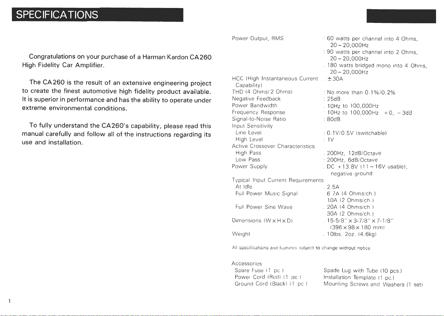
Power Output, RMS
HCC (High Instantaneous Current
Capability)
THD (4 Ohms12 Ohms)
Negative Feedback
Power Bandwidth
Frequency Response 10Hz to 100,000Hz + 0, - 3dB
Signal-to-Noise Ratio
lnput Sensitivity
L~ne Level
High Level
Active Crossover Characteristics
High Pass
Low Pass
Power Supply
x
H
x
Requirements
D)
Typical lnput Current
At Idle
Full Power MUSIC S~gnal
Full Power Sine Wave
Dimensions (W
We~ght
60 watts per channel into 4 Ohms,
20
-
20,000Hz
:
90 watts per channel into 2 Ohms,
-
20.000Hz
20
.
180 watts bridged mono into 4 Ohms,
20- 20,000Hz
.
230A
:
No more than 0.1 %10.2%
:
25dB
.
10Hz to 100,000Hz
:
80dB
:
0.1V10.5V (switchable)
:
1V
.
200Hz, 12dBlOctave
:
200Hz, 6dBlOctave
.
DC +13.8V (11 -16V usable),
negative ground
.
2.5A
6
7A (4 Ohmslch.)
(2
10A
.
20A
30A (2 Ohrnslch.)
.
15-518" x 3-718'' x 7-1!8"
.
1Olbs. 202. 14.6kgl
Ohrnsich
(4
Ohmslch
(396x98~180 rnm)
1
I
All
specifications
Accessories
Spare Fuse I1 pc
Power Cord (Red) (1 pc
Ground Cord (Black1
arltf
features subject
I
(1
to change w~rhour nonce
Spade Lug with Tube (10 pcs
1
pc
Installation Template
Mounting Screws and Washers
)
(1
pc.)
(1
set)
Page 3
30 Amperes of HCC (High Instantaneous Current Capab~lity) ma~nta~ns a
wide dynamic range and low distortion when driving low impedance or reactive loads.
4
High Power Output of 60 watts per channel Into
2
channel into
Ohms and 180 watts bridged-mono into 4 Ohms.
Ohms, 90 watts per
Ultrawide Bandwidth is achieved by the use of inherently fast open-loop
circuitry This improves transient accuracy and phase
linearity
Low Negative Feedback
Highly linear circuitry produces low
distortion
w~th only 25dB of negative feed-
back. Thls further improves dynamic accuracy.
Discrete Component Audio
Circuitry
is used because ~t was found to be
the only way to provide HCC, Ultrawide Bandwidth and Low Negarive
Feedback.
H~gh Capacity Power Supply
Two 10,000pF capacitors, six 80 watt switching transistors, and a sophisticated transformer coil design enable stable operating voltages even under
h~gh power conditions. This results In lmproved low frequency sound quality.
High Heat Diss~pat~on Capability is provided by a large heatsink, efficient
circuitry and rugged circuit components
Protection Circuitry assures high reliability under high temperature, overvoltage, reverse-voltage and short-circuit conditions, without degrading the
sound quality during normal high power operation. When the internal tem-
IS
perature reaches 175" F (80' C), the maximum output power
reduced,
which In turn reduces the operating temperature
Built-in Active Crossover and Bridged-mono features prov~de operating flexibility, system s~mplicity and added value.
Be sure that metal objects or other fore~gn mater~als do not enter the unlt
This can cause immediate trouble or reduce the unit's long-term reliability.
IS
natural for thls unlt to become warm whlle
It
operating
It ~ncorporates
two thermal protection circuits: One to prevent excessive temperatures from
being developed under normal operation, and another to shut off the unit
when operating abnormally When the thermal protection system is operatmg, the amber mdcator wdl illuminate
It is recommended that th~s unlt be operated in a vehcle only whde the
engine (and electrical charging system) is running. At high power output,
it typically draws about as much current as an automobile's headlights, and
therefore can eventually discharge the battery.
The speaker output terminals are protected from damage due to short-cir-
IS
cuited speakers or speaker wires. When this protection circuitry
IS
tarlly actlvlated, the power output
muted for several seconds and is then
momen-
restored. When the terminals are continuously short-circuited, the power output w~ll remaln muted Should the latter occur, shut off the unit and check
the speakers and speaker wires.
The heat generated by this amplif~er is dissipated into the alr by the entire
chassls If it
IS
covered, or becomes d~rty so that the clrculatlon of the alr
around it is reduced, the unit's ability to dissipate heat will also be reduced.
Under most conditions, the heat dissipating capability of this unit is more
than enough to provlde uninterrupted operation However, when full power
is drawn in an already hot environment, any loss in heat dissipating capability
is likely to result in activating one of the thermal protection circuits
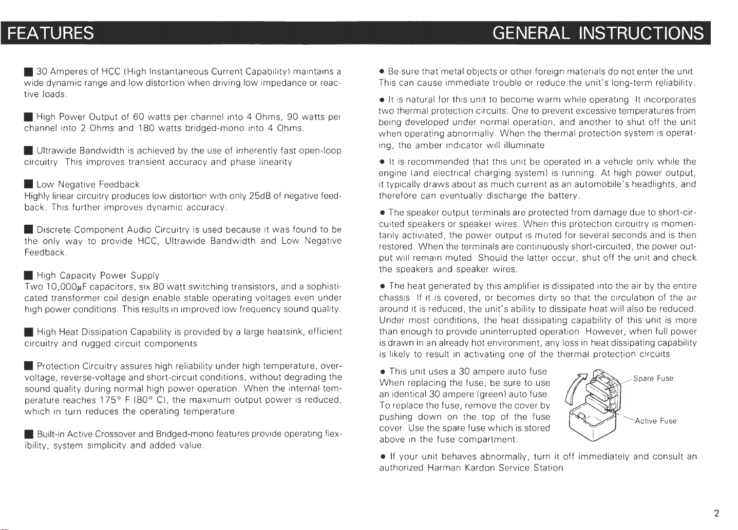
Th~s unlt uses a 30 ampere auto fuse
When replacing the fuse, be sure to use
an identical 30 ampere (green) auto fuse.
To replace the fuse, remove the cover by
pushing down on the top of the fuse
cover Use the spare fuse which is stored
above In the fuse compartment.
If your unit behaves abnormally, turn it off immediately and consult an
authorized Harman Kardon Service Station
Page 4

6?J@
-\
Installatlor1
Location
The locations shown in the above illustration are recommended for the CA260
installation. If you prefer another location, consult an authorized Harman
Kardon Dealer or Service Station before making the installation.
The recommended installation positions all result in vertical orientation of the
heatsink fins. This provides the maximum heat dissipation capability. If possible, mount the CA260 chassis directly to a vertical or near-vertical surface,
such as the lns~de wall beh~nd the rear seat. If this is not possible, use the
optional
tal surface, such as the trunk floor. The brackets permit vertical heatsink orientation when mountinq to a horizontal surface.
In addition to vertical orientation, the recommended installat~on locations allow air to flow freely through the heatsink fins. This convection, or "chimney
effect", provides maximum heat dissipation.
Horizontal heatsink orientation, such as when the unit is mounted under a
seat or directly to the trunk floor, reduces heat dissipation and causes the
unit to run hotter At low temperatures (below 70'
levels, these positions may be acceptable. But at higher temperatures andlor
power levels, these positions are likely to cause one of the thermal protec-
tion systems to activate.
Vertical Mounting Bracket (BRI)
to mount the CA260 to a horizon-
F,
20" C) or at low power
Page 5

:
Note
Note
Drill undersized holes in the car chassis so that the 5rnm tapping
screws fit t~ghtly. We recommend 3 5mm or
holes.
2:
A
template is enclosed so that the precise hole locations for the with the six 5mm hexagon-head tapping screws and spring washers. Then
tapp~ng screws can be easily determ~ned mount the
,Tern plate
118
inch diameter Using the template, locate and drill 6 holes corresponding to those in the short
Directly Mounting to a Vertical Surface
Using the template, locate and drill 6 holes corresponding to those
CA260
hexagon-head tapping screws and sprlng washers
chass~s Securely mount the
CA260
to the surface with the six 5mm
In
the
Mounting to a Horizontal Surface with the Optional Brackets (BR1)
ends of the vertical mounting brackets. Mount the brackets to the surface
CA260
bolts.
to the brackets using the six 5mm hexagon-head nuts and
Vertical
Mounting
.
Spring Washer
Spr~ng Washer
,&!$%a
Page 6

Speaker System
D+J
Left channel
0
v
ii
Car
11
Stereo
Right
channel
Leir channel
OUtOUl
u
Car Battery
Chassis
TunerIDeck
Note.
Right channel outout
Left channel output
A
tunerideck with line level
level (soeaker) outouts should
as
shown in this diagram.
outputs
and a car stereo w~th
not
he
connected simultaneously,
ngh
Page 7

Caution#
Caution#2: The last connection to be made should be that between the
Connect the CA260 to the car electrical system and to the other components
in the audio system as per the following ~nstructions:
Remote
This terminal enables the power switch of the car stereo or tunerldeck to
also turn on the CA260. Connect it to the appropriate wire on the car stereo
or tunerldeck
If a specific wire for this purpose is not provided, use the wire for controlling
the power antenna. If that wire is already connected to the power antenna,
the CA260 can be connected In addition
Should no power antenna wire be provided, an SPST (Single-Pole. SingleThrow) switch and a pair of wires can be connected between the remote
terminal and the
turn on.
1
:
The ignition key switch should be turned off before any connections are made to the car electrical system.
"
+
B"
positive terminal of the car battery and the
the CA260.
"
+
B"
terminal. When the switch is closed, the CA260 will
terminal on
+B
The + B terminal is the positive power input terminal. It should be connect-
( + )
ed to the positive
wire or an
tery terminal to protect the battery from a short circuit along the wire.
equivalent
terminal of the car battery by the enclosed 12 gauge
type. It is good practice to add a line fuse near the bat-
GND
This is the negative power input terminal It should be connected directly
to the car chassis by a short, heavy gauge wire. It is not necessary to con-
nect this terminal to the negative battery terminal.
Speaker Systems
For a conventional stereo system with one or two speaker systems per channel, connect the speaker systems to these termlnals Be careful to connect
the positive speaker terminals to the positive CA260 terminals. Do not con-
nect the negative speaker terminals to the car chassis
When one pair of speakers is used, each one may have an impedance in
-
the range of 2
of speakers are used, each one may have an impedance in the range of
Ohms and a power rating of at least
8 Ohms and a power rating of at least 60 watts If two palrs
4 - 8
45
watts.
High Level lnput
These input terminals are
that has a built-ln amplifier and does not have lme level (or preamp level)
output jacks (or wires). Connect the output wires that would normally be connected to the speakers to these terminals. Be careful to connect the car
stereo's positive output wires to the CA260's positive input terminals
If the car stereo's negative output wires are actually ground wires, they can
be twisted together and connected to the CA260's high level negative
terminal.
However, if the car stereo unit has a power rating of more than 8 watts per
channel (with low distortion), it is likely that its negative output wires are not
actually ground wires, but instead are "live." In this case, do not connect
these wires to the CA260 at all. Instead, connect a wire from the chassis
of the car stereo unit to the CA260's negative high level input terminal. If
electrical noise results from this connection method, contact the Harman
Kardon service department for a special bulletin regarding this matter.
Note: The line Input
the h~gh level lnput termlnals are connected
Line Level lnput Jacks
These input terminals are for connection to the line level (or preamp) output
jacks on the car stereo or tunerldeck It is recommended that hlgh quality
shielded coaxial cables with tight-fitting RCA plugs be used for this connection.
Line lnput Sensitivity Switch
This switch matches the line input sensitivity of the CA260 to the line output
level of the car stereo or tunerldeck. If the rated output level is equal to or
more than 0.8 volts (800 millivolts), set this switch in the "low" position.
Otherwise, set it in the "high" position.
If the line output level of the car stereo or tunerldeck is not known, assume
that it is more than 0.8 volts. When operating the total system, if it is necessary to turn the volume control of the car stereo or tunerldeck to maximum
in order to obtain a desired
to be less than 0.8 volts, and the line input sensitivity switch should be put
in the "high" position.
only
sensitivity
listening
to be used when connecting a car stereo unit
(-
switch must be set to the "low" position when
level, then the line output level is likely
Page 8

The CA260 is capable of operating as a 180 watt mono power amplifier when
4
driving a
Ohm speaker system.When used this way, two units are required
for a stereo system The instructions for connecting a stereo system using
two CA260's in the bridged-mono mode follow:
1. Each amplifier will have one speaker system connected from the left channel positive(
terminal to the right channel positive
(+
)
terminal. The
t
)
left channel positive terminal should be connected to the positive termlnal of the speaker system. No connections are made to either of the
CA260's negative speaker termlnals.
2. The input to each CA260 is made to its left channel input jack. In other
words, the left channel output of the tunerldeck is connected to the left
channel input jack of the CA260 driving the "left" speaker, and the right
channel output of the tunerldeck is made to the left channel input jack
of the CA260 driving the "right" speaker.
3.
The bridged-mono swltch on each CA260
IS
placed In the "on" position.
Note: Only one speaker system with an impedance of 4Ohms,or two speak-
ers with an impedance of 8 Ohms each, can be used in the bridged-mono
mode. Also, only speaker systems with a sufficiently high power rating can
be safely used.
Systcm
Left
channel
Speaker
System
Tuner, Deck
Left
9
chaririel
Page 9

Two CA260's can be used with two woofers (low frequency speakers) and
two mid-high (or full-range) speakers to make up an "active" system, both
amplifiers bemg drwen by the same tunerldeck. This type of system is con
nected as follows.
1
Set the filter onloff switch of one CA260 to the
"on" position. Then set the high passllow pass
switch to the "low pass" position Connect the
woofers (low frequency speakers) to thrs
amplifier
2.
Set the filter onloff switch of the other CA260 to
the "on" position Then set the h~gh passllow
pass switch to the'lhigh pass" position Connect
the mid-high (or full range) speakers to this
ampl~fier
3.
Connect the left channel input jacks of each ampl~fier to the left channel
output of the tunerldeck. Connect the right channel input jacks of each
amplifier to the r~ght channel output of the tunerldeck
FILTER
Right channel
(pJ
Left channel
Note: If the tonal balance seems to be favoring either the high or low
quency range, try using different line input sensitivity switch positions to make
the best balance. For example, if the sound is bass heavy, set the line input
sensitivity switch for the "low pass" amplifier to the "low" pos~tion. This
will reduce the signal to the woofers
200Hz
LOW
PASS HIGH PASS
/
12dBloctave 6dBioctave
\
Ire-
Speaker System
Right
channel
Left
channel
.-
-
TunerlDeck
Right channel
Left
channel
ou~put
output
 Loading...