

Page 1
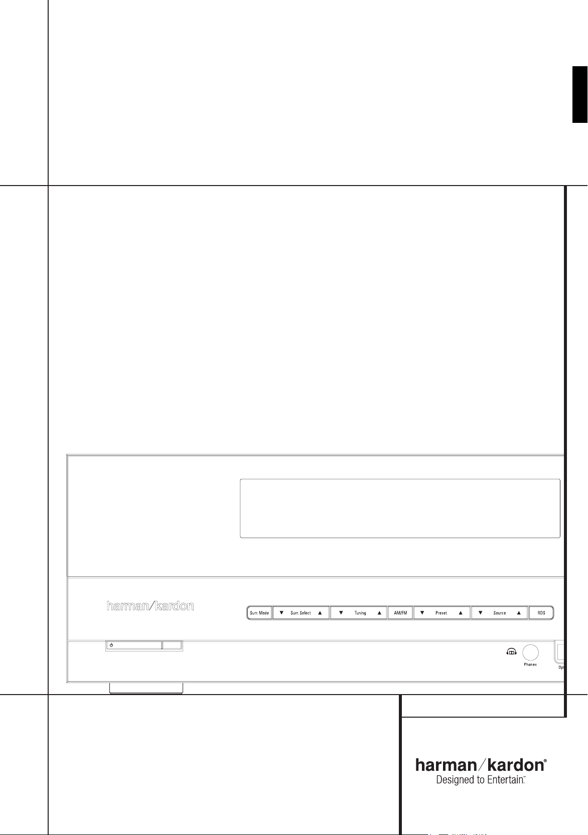
AVR 142
Audio/Video Receiver
OWNER’S MANUAL
ENGLISH
AVR 142
Page 2
Table of Contents
3 Safety Information
3 Unpacking
4 Remote Control Functions
8 Front Panel Controls
9 Rear Panel Connections
10 Installation and Connections
10 Audio Equipment Connections
10 Video Equipment Connections
11 HDMI Connections
12 System Configuration
12 First Turn On
12 Settings to be Made With Each Input Used
12 Input Setup
12 Speaker Setup
13 Surround Setup
13 Configuring the Surround Off
(Stereo) Modes
13 Stereo-Direct (Bypass) Mode
14 Stereo Digital Mode
14 Delay Settings
14 Night Mode Settings
14 Output Level Adjustment
16 Operation
16 Basic Operation
16 Source Selection
16 Controls and Use of Headphones
16 Surround Mode Selection
17 Digital Audio Playback
18 Selecting a Digital Source
18 Digital Status
18 Surround Mode Types
19 Night Mode
19 Tape Recording
19 Output Level Trim Adjustment
19 6-Channel Direct Input
19 Display Brightness
20 Memory Backup
20 Tuner Operation
20 RDS Operation
22 Troubleshooting Guide
22 Processor Reset
23 Technical Specifications AVR
DECLARATION OF CONFORMITY
We, Harman Consumer Group International
2, route de Tours
F-72500 Château-du-Loir
France
declare in own responsibility, that the product
described in this owners manual is in compliance
with technical standards:
EN55013(2001) & + A2(2006)
EN55020(2002) & + A2(2005)
EN60065:2002
EN61000-3-2(2000)+A2(2005)
EN61000-3-3 (1995)+A1(2001)+A2(2005)
EN61000-4-2(1995) & + A1(1998) & + A2(2001)
EN61000-4-3(2002) & + A1(2002)
EN61000-4-4(2004)
Jurjen Amsterdam
Harman Consumer Group Inc.
04/09
2
TABLE OF CONTENTS
Typographical Conventions
In order to help you use this manual with the remote control, front-panel controls and rear-panel connections,
certain conventions have been used.
Example – (bold type) indicates a specific remote control or front-panel button, or rear-panel connection jack
ExamplE
0
0
0
– (OCR type) indicates a message that is visible on the front-panel information display
– (number in a square) indicates a specific front-panel control
– (number in a circle) indicates a rear-panel connection
– (number in an oval) indicates a button or indicator on the remote.
Page 3
Safety Information
Important Safety Instructions
Read these instructions.1.
Keep these instructions.2.
Heed all warnings.3.
Follow all instructions.4.
Do not use this apparatus near water.5.
Clean only with a dry cloth.6.
Do not block any ventilation openings. Install in 7.
accordance with the manufacturer’s instructions.
Do not install near any heat sources such as
8.
radiators, heat registers, stoves or other apparatus
(including amplifiers) that produce heat.
Do not defeat the safety purpose of the polarized
9.
or grounding-type plug. A polarized plug has
two blades with one wider than the other. A
grounding-type plug has two blades and a third
grounding prong. The wide blade or the third
prong is provided for your safety. If the provided
plug does not fit into your outlet, consult an electrician for replacement of the obsolete outlet.
Protect the power cord from being walked on
10.
or pinched, particularly at plugs, convenience
receptacles and the point where they exit from
the apparatus.
Only use attachments/accessories specified by the 11.
manufacturer.
12. Use only with the cart, stand, tripod, bracket or
table specified by the manufacturer or
sold with the apparatus. When a cart is
used, use caution when moving the
cart/apparatus combination to avoid
injury from tip-over.
Unplug this apparatus during lightning storms or
13.
when unused for long periods of time.
Refer all servicing to qualified service personnel.
14.
Servicing is required when the apparatus has
been damaged in any way, such as power supply
cord or plug is damaged, liquid has been spilled
or objects have fallen into the apparatus, the
apparatus has been exposed to rain or moisture,
does not operate normally, or has been dropped.
Do not expose this apparatus to dripping or
15.
splashing and ensure that no objects filled
with liquids, such as vases, are placed on the
apparatus.
To completely disconnect this apparatus from the
16.
AC Mains, disconnect the power supply cord plug
from the AC receptacle.
The mains plug of the power supply cord shall
17.
remain readily operable.
Do not expose batteries to excessive heat such as
18.
sunshine, fire or the like.
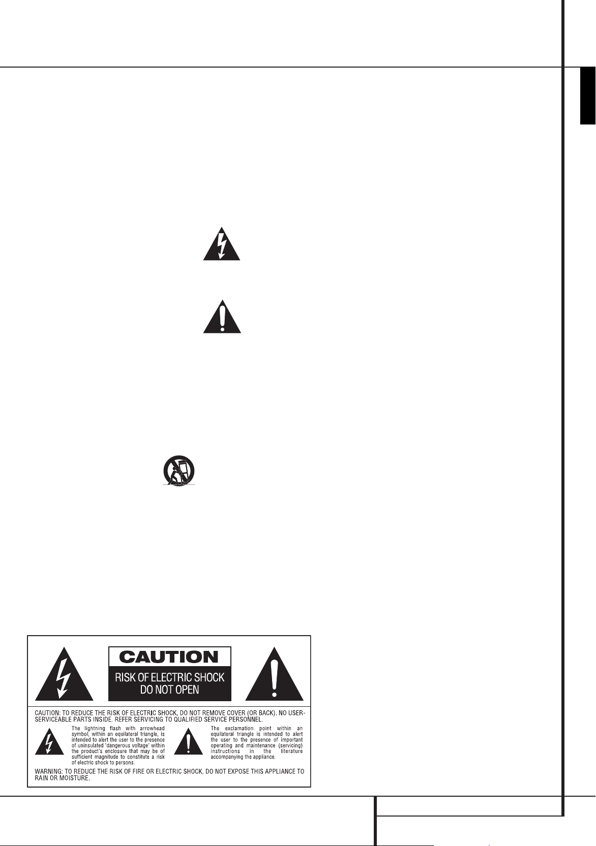
The lightning flash with arrowhead
symbol, within an equilateral triangle, is
intended to alert the user to the presence
of uninsulated “dangerous voltage” within the product’s enclosure that may be of sufficient magnitude to
constitute a risk of electric shock to persons.
The exclamation point within an equilateral triangle is intended to alert the user
to the presence of important operating
and maintenance (servicing) instructions in the literature accompanying the product.
WARNING: To reduce the risk of fire or electric shock,
do not expose this apparatus to rain or moisture.
READ THIS BEFORE OPERATING
YOUR UNIT.
Do not install this equipment in a confined space
such as a case or similar – Install it away from direct
sunlight, heat sources, vibration, dust, moisture, and/
or cold.
Avoid installing this unit where foreign objects may
fall onto this unit and/or this unit may be exposed to
liquid dripping or splashing. On the top of this unit, do
not place:
Burning objects (i.e. candles), as they may cause
fire, damage to this unit, and/or personal injury.
Containers with liquid in them, as they may fall
and liquid may cause electrical shock to the user
and/or damage to this unit.
Do not cover this unit with a newspaper, tablecloth,
curtain, etc. in order not to obstruct heat radiation. If
the temperature inside this unit rises, it may cause fire,
damage to this unit, and/or personal injury.
Install this unit near the AC outlet and where the AC
power plug can be reached easily.
This unit is not disconnected from the AC power source
as long as the Main Power Switch is ON. This state
is called the standby mode. In this state, this unit
is designed to consume a very small quantity of power.
Do Not Open the Cabinet
There are no user-serviceable components inside this
product. Opening the cabinet may present a shock
hazard, and any modification to the product will void
your guarantee. If water or any metal object such as
a paper clip, wire or a staple accidentally falls inside
the unit, disconnect it from the AC power source
immediately, and consult an authorized service
station.
Installation Location
To assure proper operation and to avoid the ■
potential for safety hazards, place the unit on a
firm and level surface. When placing the unit on a
shelf, be certain that the shelf and any mounting
hardware can support the weight of the product.
Make certain that proper space is provided both
■
above and below the unit for ventilation. If this
product will be installed in a cabinet or other
enclosed area, make certain that there is sufficient
air movement within the cabinet. Under some
circumstances a fan may be required.
Do not place the unit directly on a carpeted ■
surface.
■
Avoid installation in extremely hot or cold
locations, or an area that is exposed to direct
sunlight or heating equipment.
Cleaning
When the unit gets dirty, wipe it with a clean, soft, dry
cloth. If necessary, wipe it with a soft cloth dampened
with mild soapy water, then a fresh cloth with clean
water. Wipe dry immediately with a dry cloth. NEVER
use benzene, aerosol cleaners, thinner, alcohol or any
other volatile cleaning agent. Do not use abrasive
cleaners, as they may damage the finish of metal
parts. Avoid spraying insecticide near the unit.
Moving the Unit
Before moving the unit, be certain to disconnect any
interconnection cords with other components, and
make certain that you disconnect the unit from the
AC outlet.
ENGLISH
Unpacking
The carton and shipping materials used to protect your
new receiver during shipment were specially designed
to cushion it from shock and vibration. We suggest
that you save the carton and packing materials for use
in shipping if you move, or should the unit ever need
repair.
SAFETY INFORMATION
3
Page 4
2
0 3 4
5
6
8
9
B
D
F
H
K
C
N
O
Q
P
I
J
L
M
G
E
A
7
1
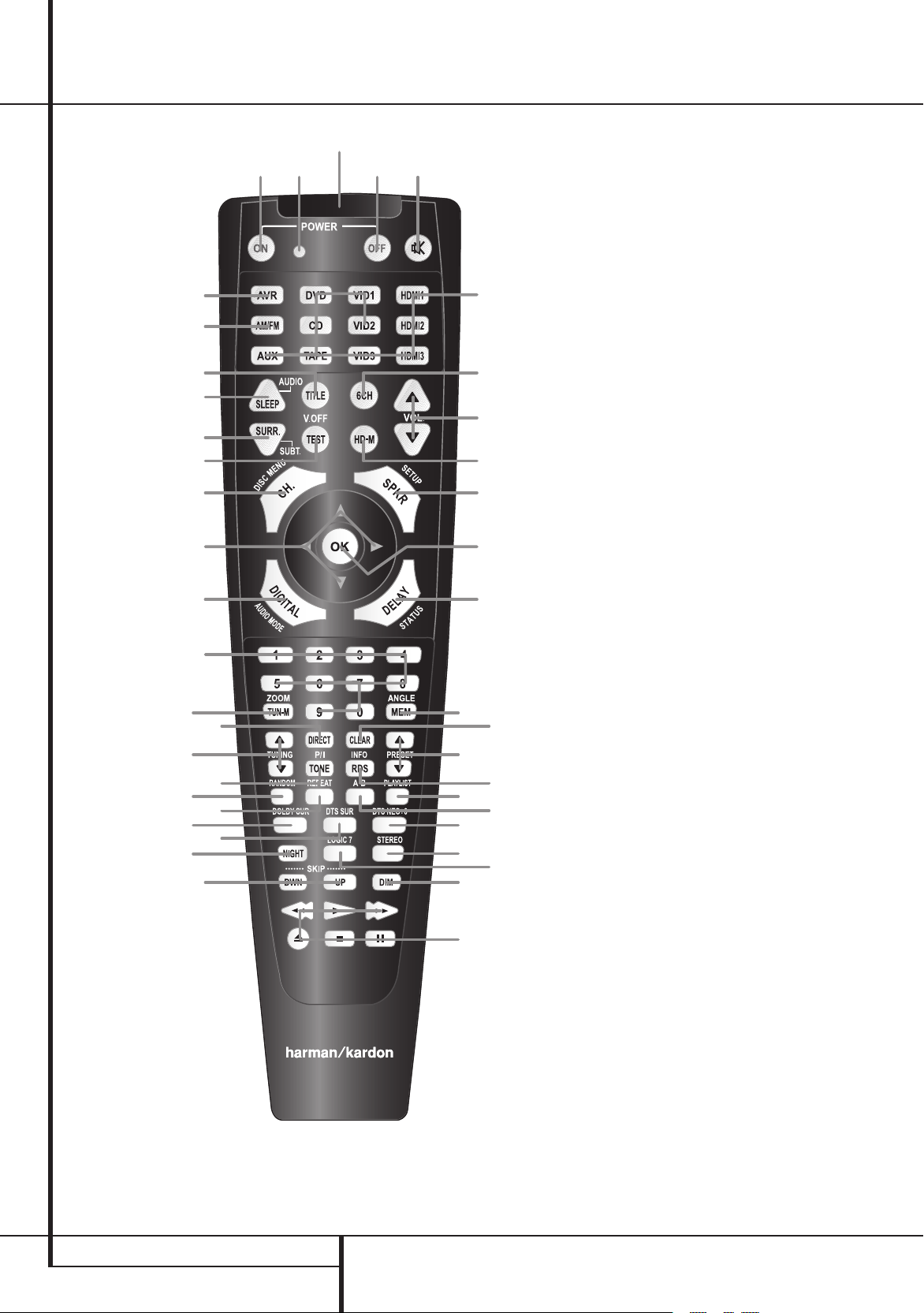
Remote Control Functions
0
Power On Button
1
Not active
2
IR Transmitter Window
3
Power Off Button
4
Mute
5
Input Selectors
6
6-Channel Direct Input
7
Volume Up/Down
8
HD Mode Selector
9
Speaker Select/Setup
A
OK Button
B
Delay/Status Button
C
Memory/Angle Button
D
Clear Button
E
Preset Up/Down
F
RDS Select/Info Button
G
Playlist
H
A-B
I
DTS Neo:6 Mode Selector
J
Stereo Mode Selector
K
Logic 7 Selector
L
Dim Button
M
Transport Buttons
N
Skip Up/Down Buttons (DWN)/(UP)
O
Night Mode
P
DTS Digital Mode Selector
Q
Dolby Mode Selector
R
Repeat
S
Random
T
Tone Mode/Progressive Scan/Interlaced
Button
U
Tuning Up/Down
V
Direct Button
W
Tuner Mode/Zoom
X
Numeric Keys
Y
Digital Select/Audio Mode
Z
Navigation Buttons
a
Channel Select /Disc Menu Button
b
V.OFF/Test Button
c
Surround Mode Selector/Program Down/
Subtitle Button
d
Sleep/Program Up/Audio Select Button
e
Title
f
AM/FM Tuner Select
g
AVR Selector
4
REMOTE CONTROL FUNCTIONS
Page 5
Remote Control Functions, common for AVR 142 and a HK DVD Player
IMPORTANT NOTE: The combined AVR and DVD
remote has some buttons that perform different
functions. If you press the AVR Button
of functions is active, identical to the functions for
buttons CD, Tape, Video 1/2/3. If you press the DVD/
HDMI1 Button
their function as indicated above the button itself,
and explained below. Refer to the function table for
an overview of functions in both modes. NOTE that
pressing the HDMI1 and DVD Buttons 5 activate
the alternative commands as seen in the Function
List on page 7. The DVD functions work with harman/
kardon DVD players only.
0
Power On Button: Press this button to turn on
the power to the AVR or the DVD selected by pressing
either the AVR or the DVD/HDMI1 Button
5
.
1
This indicator is not active.
2
IR Transmitter Window: Point this window
towards the AVR when pressing buttons on the remote
to make certain that infrared commands are properly
received.
3
Power Off Button: Press this button to place
the AVR or a selected device unit in the Standby mode.
If held for more than 3 seconds, both the AVR and the
DVD switch to Standby.
4
Mute: Press this button to momentarily silence
the AVR or TV set being controlled, depending on
which device has been selected.
5
Input Selectors: Pressing one of these buttons
will perform three actions at the same time. First, if
the AVR is not turned on, this will power up the unit.
Next, it will select the source shown on the button as
the input to the AVR. Finally, the DVD/HDMI1 Button
will switch the double-function remote buttons to
their DVD functions. After pressing the DVD/HDMI1
Button, you must press the AVR Selector button
g
again to operate all the AVR’s functions with the
remote. Note that pressing the DVD Button switches
on BOTH the AVR and the DVD, whereas pressing the
AVR Button just switches on the AVR.
5
, some of the buttons change
g
, one set
g
or
6
6-Channel Direct Input: Press this button to
select the component connected to the 6-Channel
Direct Input
wish to use the Six Channel Direct Input in conjunction
with a video source, you must first select the video
source by pressing one of the Input Selectors
Then press this button to choose the 6-Channel
Direct Input
7
or lower the system volume.
8
active with harman/kardon DVD players only.
9
to begin the process of configuring the AVR’s Bass
Management System for use with the type of speakers
used in your system. Once the button has been
pressed, use the
channel you wish to set up. Press the OK button
and then select the speaker type (see page 12 for more
information.)
For DVD: Press this button to use the DVD’s on-screen
menu system to adjust the player’s configuration
settings. Note that the Info Button
pressed to access the DVD’s Information menu to
obtain detailed disc information, and to configure the
playback mode of the disc.
A
into the AVR’s memory. It is also used in the setup
procedures for delay time, speaker configuration and
channel output level adjustment.
B
begin the process for setting the delay times used
by the AVR when processing surround sound. After
pressing this button, the delay times are entered by
pressing the OK button
buttons
button again to complete the process (See page 14 for
more information).
For DVD: Press while a disc is playing to view banner
display. Use the ARROW buttons to move through
the different features in the Banner Display. When
a symbol is highlighted, press OK on the remote to
select it.
N
as the audio. Note that when you
5
N
as the audio source.
Volume Up/Down: Press these buttons to raise
HD Mode Selector (DVD): This function is
Speaker Select/Setup: Press this button
KL
buttons Z to select the
A
6
must be
OK Button: This button is used to enter settings
Delay/Status Button: Press this button to
A
and then using the
Z
to change the setting. Press the Set
KL
.
C
Memory/Angle Button: Press this button to
enter a radio station into the AVR’s preset memory.
Two underline indicators will flash at the right side
of the Main Information Display
have five seconds to enter a preset memory location
using the Numeric Keys
information.)
For DVD: Press to access various camera angles on a
DVD (If the DVD contains multiple camera angles) or
to rotate JPEG images.
D
Clear Button: Press this button to clear incorrect
entries when using the remote to directly enter a radio
station’s frequency.
E
Preset Up/Down: When the tuner is in use,
press these buttons to scroll through the stations
programmed into the AVR’s memory. When CD or DVD
is selected using the Input Selector button
these buttons may function as Slow Fwd/Rev (DVD) or
”+10” (CD).
F
RDS Select/Info (DVD) Button: Press this
button to display the various messages that are part of
the RDS data system of the AVR’s tuner. (See page 20
for more information on RDS).
For DVD: Press for detailed informations on the disc
playing (Video/Audio Bit rate, Movie aspect ratio and
others), and for current player settings made. Note
that the unit doesn’t react on any transport button
as long as the info menu is displayed. Press again to
remove information from screen.
G
Playlist (DVD): Press this button to change the
playback order of the disc.
H
A-B (DVD): Press to select section A-B and to
play repeatedly.
I
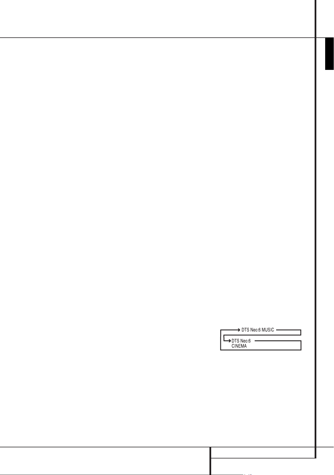
DTS Neo:6 Mode Selector: Pressing this
selector button cycles the AVR through the various DTS
Neo:6 modes, which extract a five- channel surround
field from two-channel program material (from PCM
source or analog input signal). The first press selects
the last DTS Neo:6 surround mode that was in use, and
each subsequent press selects the next mode in the
following order:
X
F
. (See page 20 for more
, you then
5
ENGLISH
,
REMOTE CONTROL FUNCTIONS
5
Page 6

Remote Control Functions, common for AVR 142 and a HK DVD Player
J
Stereo Mode Selector: Press this button to
select a stereo playback mode. When the button
is pressed so that
the Main Information Display
DSp SURR OFF
F
appears in
, the AVR will
operate in a bypass mode with true fully analog,
two-channel left/right stereo mode with no surround
processing or bass management as opposed to other
modes where digital processing is used. When the
button is pressed so that
in the Main Information Display
SURROUND OFF
F
, you may
appears
enjoy a two-channel presentation of the sound along
with the benefits of bass management. When the
button is pressed so that
5 CH STEREO
appears,
the stereo signal is routed to all five speakers, if
installed.(See page 13 for more information on stereo
playback modes).
K
Logic 7 Selector: Press this button to select one
of the available Logic 7 surround modes. (See page 16
for the available Logic 7 options).
L
Dim Button: Press this button to activate the
Dimmer function, which reduces the brightness of
the front panel display, or turn it off entirely. The first
press of the button shows the default state, which
is full brightness by indicating
Main Information Display
VFD FUll
F
. Press the button
in the
again within five seconds to reduce the brightness by
50%, as indicated by
VFD HalF
. Press the button
again within five seconds and the main display will go
completely dark. Note that this setting is temporary;
the display will always return to full brightness when
the AVR is turned on. In addition,both the Power
Indicator
2
and the blue accent lighting inside the
volume control will always remain at full brightness
regardless of the setting. This is to remind you that the
AVR is still turned on.
M
Transport Buttons: These buttons operate the
DVD player.
N
Skip Up/Down Buttons (DVD):
(DWN): Press to go to beginning of current track. Press
again quickly to go to beginning of previous track.
After pressing the PAUSE button, each press of this
button will move the image in reverse frame by frame.
(UP): Press to go to beginning of next track. After
pressing the PAUSE
button, each press of this button
will move the image forwards frame by frame.
O
Night Mode: Press this button to activate the
Night mode. This mode is available only with Dolby
Digital encoded digital sources, and it preserves dialog
(center channel) intelligibilty at low volume levels
(See page 14 for more information).
P
DTS Digital Mode Selector: When a DTS
source is in use the AVR will select the appropriate
mode automatically and no other mode will be
available. Pressing this button will display the mode
currently selected by the AVR´s decoder, depending on
the surround material played and the speaker setting.
Q
Dolby Mode Selector: This button is used to
select one of the available Dolby Surround processing
modes. Each press of this button will select one of
the Dolby Pro Logic II modes, Dolby 3 Stereo or Dolby
Digital. Note that the Dolby Digital mode is only
available with a digital input selected and the other
modes only as long as a Dolby Digital source is not
playing.
R
Repeat (DVD): Each press of this button
changes the playback mode to repeat a chapter or
track or the entire disc. A repeat icon will appear in the
upper right corner of the screen indicating the current
repeat mode. If the Player Information Screen is active,
the changes will be displayed on screen.
S
Random (DVD): Press for RANDOM playback in
random order.
T
Tone Mode/Progressive Scan/Interlaced
Button: Pressing this button enables or disables the
Bass and Treble tone controls. When the button is
pressed so that the words
Main Information Display
TONE IN
F
, the settings of
appear in the
the Bass and Treble controls will affect the output
signals. When the button is pressed so that the words
TONE OUT
Display
appear in the Main Information
F
, the output signal will be “flat,” without
any bass or treble alteration.
For DVD: Press this button to change the resolution
of the Component Video Output between standard
definition and progressive definition (PAL interlaced
and PAL progressive; NTSC interlaced and NTSC
progressive).
The new setting will become effective after quitting
the Setup menu.
U
Tuning Up/Down: When the tuner is in use,
these buttons will tune up or down through the
selected frequency band. If the Tuner Mode
W
has been pressed or the Band button 8 on the
front panel was held pressed so that
in the Main Information Display
aUTO
F
, pressing
button
appears
either of the buttons will cause the tuner to seek the
next station with acceptable signal strength for quality
reception. When the
Information Display
maNUal
appears in the Main
F
, pressing these buttons
will tune stations in single-step increments. (See page
20 for more information).
V
Direct Button: Press this button when the
tuner is in use to start the sequence for direct entry
of a station’s frequency. After pressing the button
simply press the proper Numeric Keys
X
to select
a station (See page 20 for more information on the
tuner).
W
the tuner is in use to select between automatic tuning
and manual tuning. When the button is pressed
so
Display
will move the frequency up or down in single-step
increments. When the FM band is in use and
appears in the Main Information Display
pressing this button will change to monaural reception
making even week stations audible. (See page 20 for
more information.)
When a DVD or VCD is playing, press this button to
zoom the picture so that it is enlarged. There are 4
steps to the zoom function, each progressively larger.
Press through each of the zoom stages to return to a
normal picture.
X
button numeric keypad to enter tuner preset positions.
For DVD play you may enter track numbers directly,
followed by OK to go to the track.
Y
to assign one of the digital inputs
source. (See page 10 for more information on using
digital inputs.) Audio Mode: When operating the
DVD, press this button to switch between Audio
Modes.
Z
buttons. They will be used most frequently to select
a surround mode. These buttons are also used to
increase or decrease output levels when configuring
the unit, to select speaker configuration or to select the
digital inputs.
a
button is used to start the process of setting the AVR’s
output levels with an external source. Once this button
is pressed, use the
channel being adjusted, then press the OK button
A
the level setting. (See page 19 for more information.)
DVD Disc Menu: Displays the actual DVD Disc Menu
on the TV screen in play mode. When playing discs
with JPEG images, pressing this button will access the
thumbnails.
b
output of a DVD-player for improved performance
from audio-only discs. Press again to restore video
output.
Tone: Press this button to begin the sequence used
to calibrate the AVR’s output levels. (See page 14 for
more information on calibrating the AVR).
Tuner Mode/Zoom: Press this button when
maNUal
appears in the Main Information
F
, pressing the Tuning buttons
U7
aUTO
F
Numeric Keys: These buttons serve as a ten-
Digital Select/Audio Mode: Press this button
4G9L to a
Navigation Buttons: These are multi-purpose
Channel Select /Disc Menu Button: This
KL
buttons Z to select the
, followed by the KL buttons again, to change
V.OFF/Test Button: Press to turn off video
,
6
REMOTE CONTROL FUNCTIONS
Page 7
Remote Control Functions, common for AVR 142 and a HK DVD Player
c
Surround Mode Selector/Program Down/
Subtitle Button: Press this button to begin the
process of changing the surround mode. After the
button has been pressed, use the
KL
buttons Z
to select the desired surround mode. (See page 16 for
more information).
When a DVD is playing, press to select a subtitle
language or to turn subtitles off.
Note: Due to the variations in how DVD discs are
authored, the subtitle languages selected with the
Subtitle Button may not accurately reflect the actual
languages available on the disc. It is recommended
that subtitles be selected using the disc’s menu.
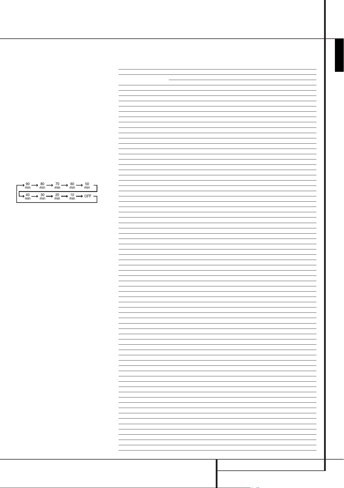
d
Sleep/Program Up/Audio Select Button:
Press this button to place the unit in the Sleep mode.
After the time shown in the display, the AVR will
automatically go into the Standby mode. Each press
of the button changes the time until turn-off in the
following order:
Hold the button pressed for two seconds to turn off the
Sleep mode setting.
DVD: Press to access various audio languages on a DVD
(If the DVD contains multiple audio streams).
e
Title: When a disc is playing, press to make the
DVD-player go back to the first section of the disc. If
you are playing a DVD-Audio disc that contains other
formats the DVD is capable of playing, such as linear
PCM or Dolby Digital 5.1, pressing this button may
enable you to switch playback from one audio format
to another.
f
AM/FM Tuner Select: Press this button to select
the AVR’s tuner as the listening choice. Pressing this
button when the tuner is in use will select between
the AM and FM bands.
g
AVR Selector: Pressing this button will switch
the remote so that it will operate the AVR’s functions.
If the AVR is in the Standby mode, it will also turn the
AVR on.
Function List
Button Name
Power ON
Power OFF Power Off (press and release) Power Off (press and release)
Mute Mute Mute(AVR)
AVR
DVD DVD DVD(AVR)
VID1 VID 1 VID 1(AVR)
HDMI1 HDMI 1 HDMI 1(AVR)
AM/FM
CD CD CD(AVR)
VID2 VID 2 VID 2(AVR)
HDMI2 HDMI 2 HDMI 2(AVR)
AUX AU X AUX(AVR)
TAPE TAPE TAPE(AVR)
VID3 VID 3 VID 3(AVR)
HDMI3 HDMI 3 HDMI 3(AVR)
SLEEP / AUDIO
TITLE Title
6CH 6CH 6CH(AVR)
VOL Up Vol Up Vol Up(AVR)
SURR. / SUBT.
TEST / V.OFF Test Tone Video Off
HD-M HD Mode
VOL Down Vol Down Vol Down(AVR)
CH. / DISC MENU
SPKR / SETUP
Level+/Up Level+/Up Up
M
Left
OK SET Enter
N
Right
Level-/Down
DIGITAL / AUDIO MODE
DELAY / STATUS Delay
1 1 1
2 2 2
3 3 3
4 4 4
5 5 5
6 6 6
7 7 7
8 8 8
TUN-M / ZOOM Tuner Mode Zoom
9 9 9
0 0 0
MEM / ANGLE Memory Angle
TUNING Up Tuning Up
DIRECT Direct Tuning
CLEAR Clear Clear
PRESET Up Preset Up
TUNING Down Tuning Down
TONE / P/I Tone Mode P/I
RDS / INFO
PRESET Down Preset Down
RANDOM Random Play
REPEAT Repeat Play
A-B
PLAYLIST Playlist
DOLBY SUR
DTS SUR DTS Surround DTS Surround(AVR)
DTS NEO:6 DTS NEO:6 DTS NEO:6(AVR)
NIGHT Night Mode Night(AVR)
LOGIC 7
STEREO Stereo Stereo(AVR)
SKIP DOWN Skip Down(DVD) Skip Down
SKIP UP Skip Up(DVD) Skip Up
DIM Dimmer Dimmer
G
) Rew(DVD) Rew
Rew(
B
) Play(DVD) Play
Play(
H
) FF(DVD) FF
FF(
Open/Close Open/Close(DVD) Open/Close
Stop Stop(DVD) Stop
Pause Pause(DVD) Pause
HK AVR Remote Command
AVR/TAPE/CD/AUX/VID1/VID2/VID3/HDMI2/HDMI3
Power On Power On
Power Off (press and hold) Power Off (press and hold)
AVR Power On AVR(AVR)
AM/FM AM/FM(AVR)
Sleep Audio
Surround Mode Subtitle
Channel Select Disc Menu
Speaker Select Setup
Left Left
Right Right
Level-/Down Down
Digital Select Audio Mode
RDS Info
Dolby Surround Dolby Surround(AVR)
Logic7 Logic7(AVR)
HK DVD Remote Command
DVD/HDMI1
Status
Slow Up
Slow Down
A-B Repeat Play
ENGLISH
REMOTE CONTROL FUNCTIONS
7
Page 8
FED
126C789A3B4G5H
AVR Audio/Video Receiver
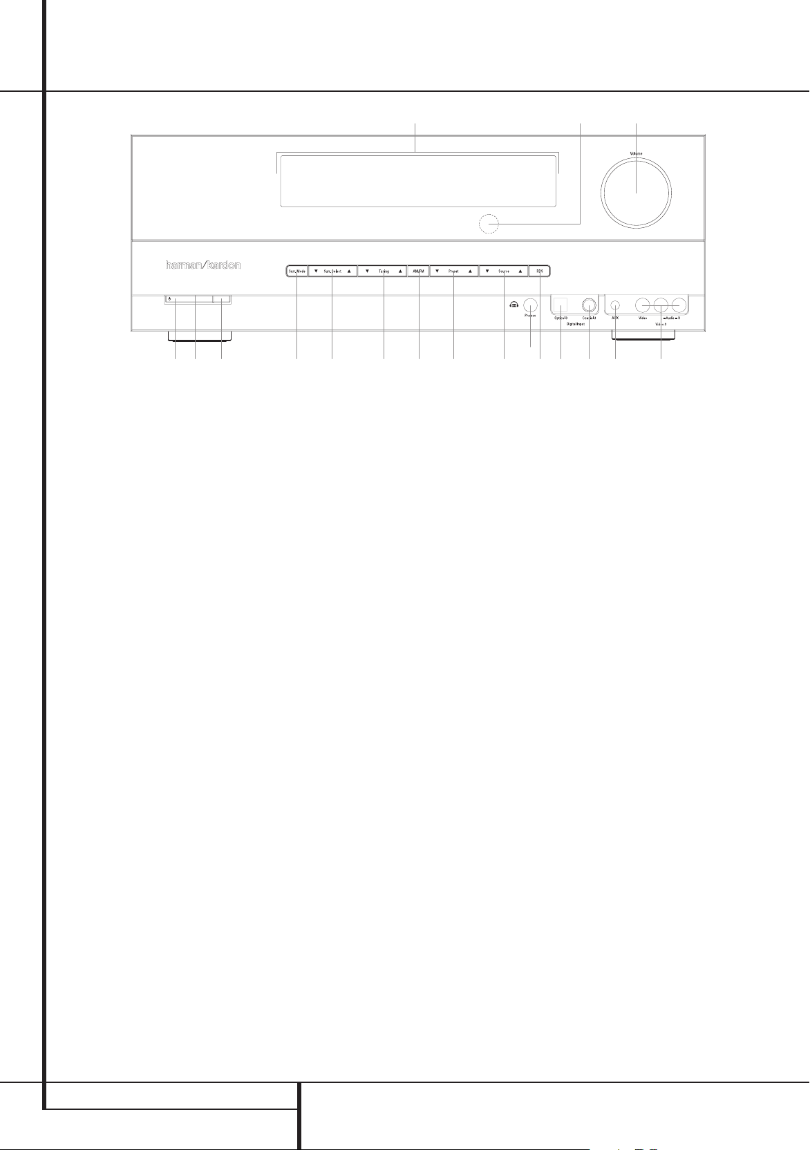
Front Panel Controls
AVR 142
0
Main Power Switch: Press this button to apply
power to the AVR. When the switch is pressed in, the
unit is placed in a Standby mode, as indicated by the
orange LED 2. This button MUST be pressed in to
operate the unit. To turn the unit off completely and
prevent the use of the remote control, this switch
should be pressed until it pops out from the front
panel so that the word “OFF” may be read at the top of
the switch.
: This switch is normally left in the “ON” position.
NOTE
1
System Power Control: When the Main Power
Switch
0
is “ON,” press this button to turn on the
AVR; press it again to turn the unit off (to Standby).
Note that the Power Indicator 2 will turn blue
when the unit is on.
2
Power Indicator: This LED will be illuminated in
orange when the unit is in the Standby mode to signal
that the unit is ready to be turned on. When the unit is
in operation, the indicator will turn blue.
3
Headphone Jack: This jack may be used to listen
to the AVR’s output through a pair of headphones.
Be certain that the headphones have a standard 6.3
mm stereo phone plug. Note that the speakers will
automatically be turned off when the headphones are
connected.
4
Digital Optical 3 Input: Connect the optical
digital audio output of an audio or video product to
this jack.
5
Aux input stereo minijack: Connect this
minijack to any audio source, typically MP3 players or
portable CD players. An analog headphone output jack
or line level out jack may be used.
6
Surround Mode Group Selector: Press this
button to select the top-level group of surround
modes. Each press of the button will select a major
mode grouping in the following order:
Dolby Modes
Stereo Modes > Logic 7 Modes
DTS Digital Modes > DSP Modes >
>
Once the button is pressed so that the name of the
desired surround mode group appears in the Lower
Display Line
Selector
available. For example, press this button to select
Dolby modes, and then press the Surround Mode
Selector
options.
7
Tuning Selector: Press the left side of the
button to tune lower frequency stations and the right
side of the button to tune higher frequency stations.
When a station with a strong signal is reached,
maNUal TUNED
in the Main Information Display
for more information on tuning stations).
8
Tuner Band Selector: Pressing this button will
automatically switch the AVR to the Tuner mode.
Pressing it again will switch between the AM and FM
frequency bands, holding it pressed for some seconds
will switch between stereo and mono receiving and
between automatic and manual tuning mode (See
page 20 for more information on the tuner).
9
Preset Stations Selector: Press this button to
scroll up or down through the list of stations that have
been entered into the preset memory. (See page 20 for
more information on tuner programming.)
A
Input Source Selector: Press this button to
change the input by scrolling through the list of input
sources.
B
RDS Select Button: Press this button to display
the various messages that are part of the RDS data
system of the AVR’s tuner. (See page 20 for more
information on RDS).
C
Surround Mode Selector: Press this button
to select from among the available surround mode
options for the mode group selected. The specific
modes will vary based on the number of speakers
available, the mode group and if the input source is
digital or analog. For example, press the Surround
Mode Group Selector
F
, press the Surround Mode
C
to cycle through the individual modes
C
to choose from the various mode
or
aUTO TUNED
6
to select a mode grouping
will appear
F
(see page 20
such as Dolby or Logic 7, and then press this button to
see the mode choices available. For more information
on mode selection, see page 13.
D
Volume Control: Turn this knob clockwise to
increase the volume, counterclockwise to decrease the
volume. If the AVR is muted, adjusting volume control
will automatically release the unit from the silenced
condition.
E
Remote Sensor Window: The sensor behind
this window receives infrared signals from the remote
control. Aim the remote at this area and do not
block or cover it unless an external remote sensor is
installed.
F
Main Information Display: This display delivers
messages and status indications to help you operate
the receiver.
G
Digital Coax 3 Input: This jack is normally used
for connection to the output of portable digital audio
devices, video game consoles or other products that
have a coax digital jack.
H
Video 3 Input Jacks: These audio/video jacks
may be used for temporary connection to video games
or portable audio/video products such as camcorders
and portable audio players.
8
FRONT PANEL CONTROLS
Page 9

Rear Panel Connections
ENGLISH
AVR 142/230
0
Tape Inputs: Connect these jacks to the PLAY/
OUT jacks of an audio recorder.
1
Tape Outputs: Connect these jacks to the
RECORD/INPUT jacks of an audio recorder.
2
Video 1 Audio Inputs: Connect these jacks to
the PLAY/OUT audio jacks on a TV or other video
source.
3
AM Antenna: Connect the AM loop antenna
supplied with the receiver to these terminals. If an
external AM antenna is used, make connections to
the AM and GND terminals in accordance with the
instructions supplied with the antenna.
4
Video 1 Audio Outputs: Connect these jacks to
the RECORD/INPUT audio jacks on a VCR or any other
Audio recorder.
5
DVD Audio Inputs: Connect these jacks to the
analog audio jacks on a DVD or other video source.
6
FM Antenna: Connect the supplied indoor or an
optional external FM antenna to this terminal.
7
CD Inputs: Connect these jacks to the analog
output of a compact disc player or CD changer.
8
Video 1 Component Video Inputs: Connect
the Y/Pr/Pb component video outputs of an HDTV Settop convertor, satellite receiver, or other video source
device with component video outputs to these jacks.
9
Coaxial Digital Inputs: Connect the coax digital
output from a DVD player, HDTV receiver, LD player, MD
player or CD player to these jacks. The signal may be
either a Dolby Digital signal, DTS signal or a standard
PCM digital source.
Do not connect the RF digital output of an LD player to
these jacks.
A
Subwoofer Output: Connect this jack to the
line-level input of a powered subwoofer. If an external
subwoofer amplifier is used, connect this jack to the
subwoofer amplifier input.
B
Video Monitor Output: Connect these jacks to
the composite input of a TV monitor or video projector
to view the output of any video source selected by the
receiver’s video switcher.
C
HDMI Inputs: Connect the HDMI output of video
sources such as a DVD player, set-top box or HDTV
tuner to either of these three jacks.
HDMI Output: Connect this jack to the HDMI
input on a compatible HDMI-equipped video display.
E
Monitor Component Video Outputs: Connect
these outputs to the component video inputs of a
video projector or monitor. When a source connected
to one of the two Component Video Inputs 8F
is selected the signal will be sent to these jacks.
F
Video 2 Component Video Inputs: Connect
the Y/Pr/Pb component video outputs of a DVD player
to these jacks.
Note: All component inputs/outputs can be used for
RGB signals too, in the same way as described for the
Y/Pr/Pb signals, then connected to the jacks with the
corresponding color.
RGB connection is not possible if the source outputs a
separate sync signal (see page 11).
G
AC Power Cord: Connect the AC plug to an
unswitched AC wall output.
H
DVD Video Inputs: Connect these jacks to the
composite output jacks on a DVD player or other video
source.
I
Video 1 Video Outputs: Connect these jacks to
the RECORD/INPUT composite jack on a VCR.
J
Video 2 Audio Inputs: Connect these jacks to the
L
Optical Digital Inputs: Connect the optical
digital output from a DVD player, HDTV receiver, LD
player, MD player or CD player to these jacks. The
signal may be either a Dolby Digital signal, a DTS
signal or a standard PCM digital source.
M
Video 1 Video Inputs: Connect these jacks to
the PLAY/OUT composite jacks on a TV or other video
source.
N
6-Channel Direct Inputs: These jacks are used
for connection to source devices such as DVD-Audio or
SACD players with discrete analog outputs.
Digital Audio Output: Connect this jack to the
matching digital input connector on a digital recorder.
Front/Center Speaker Outputs: Connect
these outputs to the matching + or – terminals on
your front/center speakers. When making speaker
connections, always make certain to maintain correct
polarity by connecting the red (+) terminals on the
AVR to the red (+) terminals on the speaker and
the black (–) terminals on the AVR to the black (–)
terminals on the speakers. (See page 12 for more
information on speaker polarity.)
Surround Speaker Outputs: Connect these
outputs to the matching + or – terminals on your left
and right surround speakers. When making speaker
connections always make certain to maintain correct
polarity by connecting the red (+) terminals on the
AVR to the red (+) terminals on the speakers and
the black (–) terminals on the AVR to the black (–)
terminals on the speakers. See page 12 for more
information on speaker polarity.
PLAY/OUT audio jacks on a VCR or other video source.
K
Video 2 Video Inputs: Connect these jacks to the
PLAY/OUT composite jacks on a second VCR or other
video source.
REAR PANEL CONNECTIONS
9
Page 10

Installation and Connections
After unpacking the unit, and placing it on a solid
surface capable of supporting its weight, you will
need to make the connections to your audio and video
equipment.
Audio Equipment Connections
We recommend that you use high-quality interconnect
cables when making connections to source equipment
and recorders to preserve the integrity of the signals.
When making connections to audio source equipment
or speakers it is always a good practice to unplug
the unit from the AC wall outlet. This prevents any
possibility of accidentally sending audio or transient
signals to the speakers that may damage them.
Important Note: In order to clearly identify all
connectors and simplify nstallation, as per the new
EIA/CEA-863 standard, all connections are colour
coded as follows:
For Speakers and Audio In/Outputs: White (Left,
speakers front) and Red (Right, speakers front).
For Speakers: Green (Center), Blue (Left Surround) and
Grey (Right Surround).
For Audio Output: Purple (Subwoofer).
For Composite Video In/Outputs: Yellow.
For Digital Audio In/Outputs: Orange.
Connect the analog output of a CD player to the 1. CD
7
inputs
NOTE: When the CD player has both fixed and variable
audio outputs it is best to use the fixed output unless
you find that the input to the receiver is so low that the
sound is noisy, or so high that the signal is distorted.
Connect the analog Play/Out jacks of a cassette 2.
deck, MD, CD-R or other audio recorder to the
Tape Input jacks
In jacks on the recorder to the Tape Output jacks
1
3.
Connect the output of any digital sources to
the appropriate input connections on the AVR
rear panel. Note that the Optical and Coaxial
digital inputs
a Dolby Digital or DTS source or the output of a
conventional CD, MD or LD player’s PCM (S/P-DIF)
output.
Assemble the AM Loop Antenna supplied with the 4.
unit as shown below. Connect it to the AM and
GND screw terminals
.
on the AVR.
0
. Connect the analog Record/
L9
may be used with
4G
3
.
Connect the supplied FM antenna to the 5. FM
(75 ohm) connection 6. The FM antenna may
be an external roof antenna, an inside powered
or wire lead antenna or a connection from a cable
system. Note that if the antenna or connection
uses 300-ohm twin-lead cable, you must use
a 300-ohm-to-75-ohm adapter to make the
connection.
Connect the front, center and surround speaker 6.
outputs to the respective speakers.
To assure that all the audio signals are carried to
your speakers without loss of clarity or resolution,
we suggest that you use high-quality speaker cable.
Many brands of cable are available and the choice of
cable may be influenced by the distance between your
speakers and the receiver, the type of speakers you use,
personal preferences and other factors. Your dealer or
installer is a valuable resource to consult in selecting
the proper cable.
Regardless of the brand of cable selected, we
recommend that you use a cable constructed of fine,
multistrand copper with an area greater than 2 mm
2
Cable with an area of 1.5 mm
runs of less than 4 m. We do not recommend that you
use cables with an area less than 1mm2 due to the
power loss and degradation in per for mance that will
occur.
When connecting wires to the speakers, be certain
to observe proper polarity. Remember to connect the
“negative” or “black” wire to the same terminal on both
the receiver and the speaker. Similarly, the “positive” or
“red” wire should be connected to like terminals on the
AVR and speaker.
NOTE: While most speaker manufacturers adhere
to an industry convention of using black terminals
for negative and red ones for positive, some
manufacturers may vary from this configuration.
To assure proper phase and optimal per formance,
consult the identification plate on your speaker or
the speaker’s manual to verify polarity. If you do not
know the polarity of your speaker, ask your dealer
for advice before proceeding, or consult the speaker’s
manufacturer.
We also recommend that the length of cable used to
connect speaker pairs be identical. For example, use
the same length piece of cable to connect the frontleft and front-right or surround-left and surround-right
speakers, even if the speakers are a different distance
from the AVR.
may be used for short
2
.
Connections to a subwoofer are normally made via
7.
a line level audio connection from the Subwoofer
A
Output
with a built-in amplifier. When a passive
subwoofer is used, the connection first goes to a
power amplifier, which will be connected to one or
more subwoofer speakers.
If you are using a powered subwoofer that does
not have line-level input connections, follow
the instructions furnished with the speaker for
connection information.
Note
: Speaker sets with two front satellites and
a passive subwoofer must be connected to the
front speaker outputs only rather than to the
Subwoofer Output
8.
If an external multi-channel audio source with
5.1 outputs such as an external digital processor/
decoder, DVD-Audio or SACD™ player is used,
connect the outputs of that device to the
6-Channel Direct Inputs
to the line-level input of a subwoofer
A
.
N
.
Video Equipment Connections
Video equipment is connected in the same manner
as audio components. Again, the use of high-quality
interconnect cables is recommended to preserve signal
quality.
Connect a VCR’s audio and video Play/Out jacks to 1.
the Video 2 In jacks JK on the rear panel. The
Audio and Video Record/In jacks on the VCR should
be connected to the Video 1 Out jacks
on the AVR.
2.
Although any video device may be connected to
these jacks, we recommend connecting your TV to
the Video 1 Audio/Video Input Jacks
that you may take advantage of the fact that the
remote control is preprogrammed with TV product
codes for the Video 1 device.
For the same reason, we recommend connecting
your video recorder, cable TV converter or satellite
receiver to the Video 2 Audio/Video Input
JK
Jacks
3.
Connect the analog audio and video outputs of a
DVD to the DVD jacks
if your DVD player does not have a HDMI Output.
If a HDMI Output is available on the DVD player,
connect it to the HDMI Inputs C. Please note
that these Inputs are Video only. Audio must be
connected separately.
Connect the digital audio outputs of a CD, MD or
4.
DVD player, satellite receiver, cable box or HDTV
converter to the appropriate Optical or Coaxial
Digital Inputs
Remember that the DVD source defaults to the
Coaxial 1 Digital Input
default to their analog inputs, although any source
may be assigned to any digital audio input on the
receiver.
.
5C
. This is valid only
9L
.
4G
9
. All other sources
4I
2M
so
10
INSTALLATION AND CONNECTIONS
Page 11

Installation and Connections
Connect the 5. Composite Monitor Output B
jacks on the receiver to the composite input of your
television monitor or video projector.
If your DVD player and monitor both have
6.
component video connections, connect the
component outputs of the DVD player to the
Video 1 Component Video Inputs 8. Note
that even when component video connections are
used the audio connections must still be made to
either the analog DVD Audio Inputs
of the Coaxial or Optical Digital Input jacks
9L
.
7.
If another component video device is available,
connect it to the Video 2 Component Video
Input jacks
device should be made to either the Video 2
Input jacks
Digital Input jacks
8.
If the component video inputs are used, connect
the Component Video Output E to the
component video inputs of your TV, projector or
display device.
If you have a camcorder, video game or other audio/
9.
video device that is connected to the AVR on a
temporary, rather than permanent basis, connect
the audio, video and digital audio outputs of that
device to the Front Panel Inputs
A device connected to the Video 3 jacks
selected as the Video 3 input, and connected to
the digital jacks
3" or "Coaxial 3" input. (See page 14 for more
information on input configuration.)
Connect the AVR to your video display using one of 10.
the following connections, even if you will also use
an HDMI connection:
•
•
F
. The audio connections for this
J
or any of the Coaxial or Optical
9L
.
4G
it is selected as "Optical
If your video display has component
video inputs (Y/Pr/Pb), connect the
ComponentVideo Output K.
If your display does not have component video
inputs, connect the Video Monitor Output
B
(Composite) on the AVR to the matching
input on your display. Only one connection is
needed.
5
4GH
or any
.
H
is
HDMI Connections
HDMI™ is the abbreviation for High-Definition
Multimedia Interface, which is quickly becoming the
standard connection point between advanced video/
audio source products and displays, particularly
for high-definition video signals. HDMI is a digital
connection, eliminating the need to convert signals
back and forth from digital to analog.
Some source or display components in your system
may use DVI (Digital Video Interface) for digital video
connections. DVI carries the same digital video signals
as HDMI but uses a larger connector and does not
transport audio or control signals. In most cases,
you may mix and match DVI and HDMI digital video
connections by using optional connector adapters.
Note, however, that some DVI-equipped video displays
are not compatible with the HDCP copy protection
coding that is increasingly carried with signals
connected via HDMI. If you have an HDMI source and a
DVI-equipped display, you may occasionally be unable
to view a program if the display does not include HDCP.
This is not the fault of the AVR or your source; it simply
indicates that the video display is not compatible.
The AVR 142 is equipped for HDMI switching, which
means that it is able to select either of the three HDMI
inputs as the source that feeds your system’s video
display. This preserves the digital signal in its original
form by passing it directly through from source to
display. However, this also means that the AVR does
not have access to the signal and thus it is not able to
add menus or on-screen messages to HDMI signals, or
to process the audio that may be part of the signal in
an HDMI connection.
Therefore, the following connections are required
when the AVR is used with HDMI sources:
Connect the HDMI output of a source to either of
•
the HDMI Inputs
• HDMI Output of the AVR to an
Connect the
HDMI input on your display.
•
Connect either an optical or coaxial digital audio
output from the source to the AVR. The default
connections are Coaxial 2
connected to HDMI 1
source connected to HDMI 2
digital or analog audio source in conjunction with
the HDMI inputs, but if it varies from the default
you must make a change to the input’s setting, as
shown on page 18.
Even when HDMI inputs are used, it is important
•
to make sure that a component or composite
video connection is made between the AVR and
your display. This is needed to view both the
setup menus and onscreen messages, and to
view other (non-HDMI) video sources. The AVR
does not convert analog video signals to HDMI.
All component inputs/outputs can be used for RGB •
signals too, in the same way as described for the
Y/Pr/Pb signals, then connected to the jacks with
the corresponding color. But this is only correct
as long as only the three RGB video signals are
output by the video source, with a sync signal in
the "G" signal only, without any sync signal output
separately by the source.
C
.
9
for a source
C
and Optical 2 L for a
. You may use any
ENGLISH
Video Connection Notes:
Y/Pr/Pb Component, RGB, or Composite video •
signals may only be viewed in their native formats
and will not be converted to the other formats.
All component inputs/outputs can be used for RGB •
signals too, in the same way as described for the
Y/Pr/Pb signals, then connected to the jacks with
the corresponding color. But this is only correct
as long as only the three RGB video signals are
output by the video source, with a sync signal in
the "G" signal only, without any sync signal output
separately by the source.
INSTALLATION AND CONNECTIONS
11
Page 12

System Configuration
Once the speakers have been placed in the room
and connected, the remaining steps are to program
the system configuration memories. With the AVR
two kind of memories are used, those associated
individually with the input selected, e.g. surround
modes, and others working independently from any
input selected like speaker output levels, or delay
times used by the surround sound processor.
First Turn On
You are now ready to power up the AVR to begin these
final adjustments.
1. Power Cable G into an un switched
Plug the
AC outlet.
2. Main Power Switch 0 in until it
Press the
latches and the word “OFF” on the top of the switch
disappears inside the front panel. Note that the
Power Indicator
that the unit is in the Standby mode.
Remove the protective plastic film from the front-3.
panel lens. If left in place, the film may affect the
performance of your remote control.
4.
Install the three supplied AAA batteries in the
remote as shown. Be certain to follow the (+) and
(–) polarity indicators that are on the bottom of
the battery compartment.
Turn the AVR on either by pressing the 5. System
Power Control
Selector
by pressing the AVR Selector
Input Selectors
Indicator
unit is on, and the Main Information Display
F
will also light up.
: After pressing one of the Input Selector
NOTE
buttons
5
Selector
g
functions.
2
will turn orange, indicating
1
or the Input Source
A
on the front panel, or via the remote
g
or any of the
5
on the remote. The Power
2
will turn blue to confirm that the
to turn the unit on, press the AVR
to have the remote control the AVR
Settings to be Made With Each
Input Used
The AVR features an advanced memory system that
enables you to establish different settings for the
speaker configuration, digital input, surround mode,
delay times and output levels for each input source.
This flexibility enables you to custom tailor the way
in which you listen to each source and have the AVR
memorize them. This means, for example, that you
may associate different surround modes and analog
or digital inputs with different sources, or set different
speaker configurations with the resultant changes
to the bass management system or the use of the
Center speaker. Once these settings are made, they
will automatically be recalled when ever you select an
input.
The default settings for the AVR, as it is shipped from
the factory, have all inputs set for an analog source
(except for the DVD input, which has the Coaxial
Digital Input 1
Music as the surround mode, all speaker positions set
to "small", and a subwoofer connected. Before using
the unit, you will probably want to change these
settings for most inputs so that they are properly
configured to reflect the use of digital or analog inputs,
the type of speakers installed and the surround mode
associated with the input.
Input Setup
The first step in configuring the AVR is to select an
input. This may be done by pressing the front panel
Input Source Selector
name appears in the Main Information Display
F
. The input may also be selected by pressing the
appropriate Input Selector on the remote control
5g
The second step is to associate one of the digital
inputs with the selected input source (if this is needed,
otherwise the selected analog input will remain).
Press the Digital Input Select button
the remote. Within five seconds, make your input
selection using the
until the desired digital or analog input is shown in
the
Main Infor ma tion Display F. Then press
the OK button
assignment.
After the setting has been made with one input, repeat
as described above with all inputs in use. The digital
input associated with the input selected can also be
changed at any time later and the AVR’s memory
system will keep the settings until they are changed
again.
9
as the default), with Logic 7
A
until the desired input’s
.
Y
on
KL
buttons Z on the remote
A
to enter the new digital input
Speaker Setup
This setup tells the AVR which type of speakers are in
use. This is important as it adjusts the settings that
determine which speakers receive low frequency
(bass) information and whether a Center speaker
should be used or not, separately for each input
used. For each of these settings use the
setting if the speakers for a particular position are
traditional full-range loudspeakers that are capable of
reproducing sounds below 100Hz. Use the
setting for smaller, frequency-limited satellite speakers
that do not reproduce sounds below 100Hz. Note that
when “small” front (left and right) speakers are used,
a subwoofer is required to reproduce low frequency
sounds. If you are in doubt as to which category
describes your speakers, consult the specifications in
the speakers’ owner’s manual, or ask your dealer.
With the AVR turned on, follow these steps to
configure the speakers:
Press the
1. Speaker button 9 on the remote.
The words
the Main Information Display
2. OK button A.
Press the
Press the
3.
FRONT laRGE
matching the type of speakers you have at the leftfront and right-front positions, as described by the
definitions shown in preceding section.
When
channel sounds will be sent only to the subwoofer
output. Note that if you choose this option and there
is no subwoofer connected, you will not hear any low
frequency sounds from the front channels. This setting
is not available with stereo mode to ensure purest
sound by bypassing the crossovers of the DSP´s.
When
will be sent to the front left and front right outputs.
Depending on the subwoofer configuration (see
below), the front left and right bass information may
also be directed to a subwoofer.
Important Note: When a speaker set with two front
satellites and a passive subwoofer is used, connected
to the front speaker outputs, the fronts must be set
for
laRGE
When you have completed your selection for the front
4.
channels, press the OK button A, and then press
the
the display to
FRONT SpEaKER
KL
buttons Z on the remote to select
or
FRONT Small
Small
is selected, low frequency front
laRGE
is selected, a full-range output
.
KL
buttons Z on the remote to change
CENTER SpEaKER
laRGE
Small
will appear in
F
.
,
.
12
SYSTEM CONFIGURATION
Page 13

System Configuration
Press the 5. OK button A again, and use the
buttons
Z
on the remote to select the option
KL
that best describes your system based on the
Center speaker definitions shown in preceding
section.
Small
When
is selected, low frequency center
channel sounds will be sent to the Fronts, if they are
set for
laRGE
and Sub is turned off. When Sub is on,
low frequency center channel sounds will be sent to
the subwoofer only.
laRGE
When
is selected, a full-range output will be
sent to the center speaker output, and with analog and
digital surround modes (except with the Pro Logic II
Music mode) NO center channel signal will be sent to
the subwoofer output.
When
NONE
is selected, no signal will be sent to
the center channel output. The receiver will operate
in a “phantom” center channel mode and center
channel information will be sent to the left and right
front channel outputs and its bass will be sent to
the subwoofer output too as long as SUB L/R+LFE
is selected in the SUBWOOFER line in this menu (see
below). This mode is needed if no Center speaker is
used. Note that for the use of Logic 7C surround mode
a Center speaker is needed, but Logic 7M works well
without a Center too.
When you have completed your selection for the 6.
center channel, press the OK button A, and
then press the
to change the display to
7. OK button A again, and then use the
Press the
KL
KL
buttons Z on the remote
SURR SpEaKER
buttons Z on the remote to select the
.
option that best describes your system based
on the Surround speaker definitions shown in
preceding section.
Small
When
is selected, with all digital surround
modes low frequency surround channel sounds will
be sent to the Fronts, when Sub is turned off, or to the
subwoofer output when Sub is on. With the analog
surround modes the rear bass feed depends on the
mode selected and the setting of the sub and front
speakers.
When
laRGE
is selected, a full-range output will be
sent to the surround channel outputs (with all analog
and digital surround modes), and, except with Hall
and Theater modes, NO surround channel bass will be
sent to the subwoofer output.
When
NONE
is selected, surround sound information
will be split between the front-left and front-right
outputs. Note that for optimal performance when no
surround speakers are in use, the Dolby 3 Stereo mode
should be used instead of Dolby Pro Logic.
When you have completed your selection for the 8.
surround channel, press the OK button A, and
then press the
to change the display to
9. OK button A, and then press the KL
Press the
buttons
KL
buttons Z on the remote
S-W SpEaKER
Z
on the remote to select the option
that best describes your Subwoofer system.
The choices available for the subwoofer position
will depend on the settings for the other speakers,
particularly the front left/right positions.
If the front left/right speakers are set to
subwoofer will automatically be set to
Small
SUB
the “on” position.
If the front left/right speakers are set to
laRGE
three options are available:
•
If no subwoofer is connected to the AVR, press the
arrow buttons
Z
so that
SUB NONE
in the display. When this option is selected, all bass
information will be routed to the front left/right
“main” speakers.
If a subwoofer is connected to the AVR, you have
•
the option to have the front left/right “main”
speakers reproduce bass frequencies at all times,
and have the subwoofer operate only when
the AVR is being used with a digital source that
contains a dedicated Low Frequency Effects, or
LFE soundtrack. This allows you to use both your
main and subwoofer speakers to take advantage
of the special bass created for certain movies. To
select that option press the arrow buttons
that
SUB lFE
•
If a subwoofer is connected and you wish to use it
appears in the display.
for bass reproduction in conjunction with the main
front left/right speakers, regardless of the type of
program source or surround mode you are listening
to, press the arrow buttons
R+lFE
appears in the display. When this option
Z
so that
is selected, a “complete” feed will be sent to the
front left/right “main” speakers, and the subwoofer
will receive the front left and right bass frequencies
under the crossover frequency 80 Hz, additionally
to the LFE soundtrack (see above).
When all speaker selections have been made for 10.
the input selected, press the OK button A twice
or simply wait for three seconds until the display
returns to the normal mode.
.
, the
, which is
,
appears
Z
so
SUB l/
Surround Setup
Once the speaker setup has been completed, the next
setup step is to set the surround mode you wish to use
with each input. Since surround modes are a matter of
personal taste, feel free to select any mode you wish –
you may change it later. To make it easier to establish
the initial parameters for the AVR, it is best to leave the
default setting of Logic 7 Music mode for most analog
inputs and Dolby Digital for inputs connected to digital
sources. In the case of inputs such as a CD Player, Tape
Deck or Tuner, you may wish to set the mode to Stereo,
if that is your preferred listening mode for standard
stereo sources, where it is unlikely that surround
encoded material will be used.
To set the surround mode you wish to use with the
input selected, press the Surround Mode Selector
button
6
on the front or
cZ
on the remote
until the desired surround mode´s name appears in
the Main Information Display
F
.
Note that Dolby Digital and DTS will only appear as
choices when a digital input has been selected.
After the surround mode setting has been made with
the current input, repeat the setting with all inputs
you will use. The surround mode can also be changed
at any time later, and the AVR’s memory system will
keep the settings for the input selected, until they are
changed again.
Configuring the Surround Off
(Stereo) Modes
For superior reproduction of two-channel program
materials, the AVR offers two Stereo modes: an
analog Stereo-Direct mode that bypasses the digital
signal processing circuitry for a completely analog
signal path that preserves the purity of the original
signal, and a digital mode that is capable of providing
bass management for optimal distribution of the
low frequencies between smaller speakers and a
subwoofer.
Stereo-Direct (Bypass) Mode
When the analog Stereo-Direct mode is selected
by pressing the Stereo Mode Selector J
until
SURROUND OFF
Information Display
analog source material directly through to the front left
and right speakers, bypassing the digital processing
circuitry.
In this mode, the front left and right speakers will
automatically be configured as
possible to configure these speakers as
appears in the Main
F
the AVR will pass the
laRGE
Small
; it is not
.
ENGLISH
SYSTEM CONFIGURATION
13
Page 14

System Configuration
When the AVR is in the Stereo Bypass mode you may
still configure the subwoofer output so that it is either
turned off, with a full-range signal going to the front
left/right speakers, or you may configure it so that the
subwoofer feed is activated. The factory default setting
is to have the subwoofer turned off for this mode, but
you may change that setting by following these steps:
1. Speaker Button 9.
Press the
2. OK Button A to activate the
Press the
configuration menu.
3.
the desired option.
feed to the subwoofer, while
Buttons Z on the remote to select
SUB NONE
turns off the
SUB <l+R>
turns
KL
Press the
it on.
4.
When the desired setting has been entered,
press the OK Button A to return to normal
operation.
Stereo-Digital Mode
When the Stereo-Direct (Bypass) mode is in use
a full range signal is always sent to the front left/
right speakers. By its nature, that option does not
pass the signal through the AVR’s digital signal
processing, creating the requirement for full-range
speakers. If your front speakers are bandwidth
limited, “satellite”speakers, we recommend that you
do NOT use the Bypass mode, but rather use the
DSp SURROUND OFF
mode for stereo listening.
To listen to programs in the two-channel stereo mode
while taking advantage of the bass management
system, press the Stereo Mode Selector J
until
SURROUND OFF
Information Display
appears in the Main
F
.
When this mode is in use, the front left/right speakers
and subwoofer may be configured to meet the
requirements of your specific speakers using the steps
shown in the Speaker Setup section.
Delay Settings
Only for the Dolby or DTS modes, you will need to
adjust the delay time setting. Note that the delay time
is not adjustable for any other modes.
Due to the different distances between the listening
position for the front channel speakers and the
surround speakers, the amount of time it takes for
sound to reach your ears from the front or surround
speakers is different. You may compensate for this
difference through the use of the delay settings to
adjust the timing for the specific speaker placement
and acoustic conditions in your listening room or
home theater.
The factory setting is appropriate for most rooms,
but some installations create an uncommon distance
between the front and surround speakers that may
cause the arrival of front channel sounds to become
disconnected from surround channel sounds.
To resynchronize the front, center and surround
channels, follow these steps:
Measure the distance from the listening/viewing 1.
position to the front speakers in meters.
Measure the distance from the listening/viewing 2.
position to the surround speakers.
Press the 3. Delay Button B.
4.
5.
FRONT l DElaY
When
Information Display
A
.
KL
Press the
Buttons Z on the remote to enter
appears in the Main
F
press the OK Button
the distance from the front left/right speakers to
your listening position. Press the OK Button
A
when this is complete.
6.
7.
KL
Press the
that
CENTER DElaY
Buttons Z on the remote so
Information Display
Button
A
(After
CENTER DElaY
see
FRONT R DElaY
KL
Press the the
Buttons Z on the remote
appears in the Main
F
and press the OK
).
, you will
to enter the distance from the center speaker to
your listening position. Press the OK Button
A
when this is complete.
8.
KL
Press the
so that
SURR DElaY l
Buttons Z on the remote
SURR DElaY R
and after that
appears in the Lower Display
Line and press the OK Button A.
Press the the
9.
KL
Buttons Z on the remote to
enter the distance from the surround speakers to
your listening position. Press the OK Button
A
when this is complete.
10.
When all adjustments have been made, the unit
will return to normal operation in five seconds.
Night Mode Settings
The Night mode is a feature of Dolby Digital that uses
special processing to preserve the dynamic range
and full intelligibility of a movie sound track while
reducing the peak level. This prevents abruptly loud
transitions from disturbing others, without reducing
the sonic impact of a digital source. Note that the
Night mode is only available when the Dolby Digital
surround mode is selected.
To adjust the Night mode setting press the Input
A
Source Selector
remote and select an input that is associated with a
digital input and the Dolby Digital surround mode.
on the front or 5 on the
Next press the Night button O on the remote.
When the button is pressed, the words
D-RaNGE
(Dynamic Range) followed by the current setting (MID,
MAX, OFF) will appear in the Main Information
Display
F
. Press the
KL
buttons Z within five
seconds to select the desired setting:
OFF
: When OFF is shown in the display, the Night
mode will not function.
mID
: When MID is shown in the display, a mild
compression will be applied.
max
: When MAX is shown in the display, a more
severe compression algorithm will be applied.
When you want to use the Night mode feature, we
recommend that you select the MID setting as a
starting point and change to the MAX setting later, if
desired.
Output Level Adjustment
Output level adjustment is a key part of the
configuration process for any surround sound product.
It is particularly important for a Dolby Digital receiver
such as the AVR, as correct outputs will ensure that
you hear sound tracks with the proper directionality
and intensity.
: Listeners are often confused about the
NOTE
operation of the surround channels. While some
assume that sound should always be coming from
each speaker, most of the time there will be little or no
sound in the surround channels. This is because they
are only used when a movie director or sound mixer
specifically places sound there to create ambiance,
a special effect or to continue action from the front
of the room to the rear. When the output levels are
properly set it is normal for surround speakers to
operate only occasionally. Artificially increasing the
volume to the rear speakers may destroy the illusion of
an enveloping sound field that duplicates the way you
hear sound in a movie theater or concert hall.
IMPORTANT NOTE: The output level can be adjusted
for each digital and analog surround mode separately.
This allows you to compensate for level differences
between speakers, that may also vary with the
surround mode selected, or to increase or decrease the
level of certain speakers intentionally, depending on
the surround mode selected. Note that adjustments
made for any surround mode are effective with all
inputs associated with that surround mode.
14
SYSTEM CONFIGURATION
Page 15

System Configuration
Before beginning the output level adjustment process,
make certain that all speaker connections have been
properly made. The system volume should be turned
down at first.
For the easiest set-up, follow these steps while seated
in the listening position that will be used most often:
1.
Make certain that all speaker positions have been
properly configured for their “large” or “small”
settings (as outlined above).
2.
Adjust the volume so that it is at
-15
, as shown
in the on-screen display or Main Information
Display
F
.
To adjust and calibrate the output levels, follow these
steps. For accurate calibration, it is a good idea to
make these adjustments while seated in your favorite
listening position. As the adjustment must be made
for each surround mode, it is best to select any input
associated with any Dolby Pro Logic II mode, make the
adjustment for that surround mode, then step through
all inputs you´re using (and thus through all surround
modes associated with the inputs) and repeat the
adjustment when any surround mode appears that has
not yet been adjusted.
Select any input associated with any Dolby 1.
Pro Logic II surround mode by pressing the
Input Source Selector
pRO lOGIC II
Information Display
2. Test button b on the remote. The
Press the
words
T-T Fl 0DB
Information Display
A5
until
is shown in the Main
F
.
will appear in the Main
F
.
The test noise will immediately begin to circulate 3.
in the speakers in a clockwise rotation, pausing at
each position for two seconds. As the test noise
rotates the speaker positions
Sl
(Front Left, Center, Front Right, Surround
Fl, C, FR, SR
,
Right, Surround Left) will be shown in the Main
Information Display
F
. Turn up the volume
now until you can hear the noise clearly.
IMPORTANT NOTE
: Because this test noise will have
a much lower level than normal music, the volume
must be lowered after the adjustment for all channels
is made, BEFORE you turn the test tone off.
NOTE: This is a good time to verify that the speakers
have been properly connected. As the test noise
circulates, listen to make certain that the sound
comes from the speaker position shown in the Main
Information Display. If the sound from a speaker
location does NOT match the position indicated in
the display, turn the AVR off using the Main Power
Switch
0
and check the speaker wiring to make
certain that each speaker is connected to the correct
output terminal.
After checking for speaker placement, let the test noise
circulate again, and listen to see which channels sound
louder than the others. Using the front left speaker as a
reference, press the
KL
buttons Z on the remote
to bring all speakers to the same volume level. Note
that when one of the
KL
buttons is pushed, the
test noise circulation will pause on the channel being
adjusted to give you time to make the adjustment.
When you release the button, the circulation will
resume after five seconds.
Continue to adjust the individual speakers until they all
have the same volume. Note that adjustments should
be made with the
KL
buttons Z on the remote
only, NOT the main volume controls.
When all channels have the same output level,
turn the Volume
D7
down to about –40dB,
otherwise the listening level may be too high as soon
as the source’s music starts to play. After wards press
the Test Button b again to turn the test tone off
and complete the process.
IMPORTANT NOTE: The Output level adjustment
made will be effective for the surround mode currently
selected, also when other inputs are selected using
the same surround mode. To adjust the output level
with all other surround modes used, step through all
inputs you´re using by pressing the Source Selector
buttons
A
on the front panel or the appropriate
Input Selectors
5
on the remote. When the
indicator for any surround mode for which the level
adjustment has not yet been made lights in the
Main Information Display
F
, repeat the level
adjustment described above. This will also allow you
to compensate level differences between speakers,
that may be different with each surround mode, or
to increase or decrease the level of certain speakers
intentionally, depending on the surround mode
selected.
Once the settings outlined on the previous pages have
been made, the AVR is ready for operation. While there
are some additional settings to be made, these are
best done after you have had an opportunity to listen
to a variety of sources and different kinds of program
material. In addition, any of the settings made in the
initial configuration of the unit may be changed at any
time. As you add new or different sources or speakers,
or if you wish to change a setting to better reflect
your listening taste, simply follow the instructions for
changing the settings for that parameter as shown
above. Note that any settings changed at any time,
will be stored in memory in the AVR, also if it´s turned
off completely, unless reset (see page 22).
Having completed the setup and configuration process
for your AVR, you are about to experience the finest in
music and home theater listening. Enjoy!
ENGLISH
SYSTEM CONFIGURATION
15
Page 16

Operation
Basic Operation
Once you have completed the setup and configuration
of the AVR, it is simple to operate and enjoy. The
following instructions should be followed for you to
maximize your enjoyment of your new receiver:
Turning the AVR On or Off
When using the AVR for the first time, you must •
press the Main Power Switch
panel to turn the unit on. This places the unit in a
Standby mode, as indicated by the orange color
of the Power Indicator 2. Once the unit is
in Standby, you may begin a listening session
by pressing the System Power Control 1 or
the Source button
the AVR Selector on the Remote Control
Note that the Power Indicator
blue. This will turn the unit on and return it to
the input source that was last used. The unit may
also be turned on from Standby by pressing any
of the Source Selector buttons on the remote
5fg
: After pressing the the DVD or HDMI 1 Button
Note
5
to turn the unit on, press the AVR Selector g
to have the remote control all of the AVR functions.
Please refer to the Remote Function List on page 7 for
an overview.
To turn the unit off at the end of a listening session,
simply press the System Power Control 1 on the
front panel or the Power Off Button
remote.
When the remote is used to turn the unit “off ” it is
actually placing the system in a Standby mode, as
indicated by the orange color of the Power Indicator
2
.
When away from home for an extended period of time
it is always a good idea to completely turn the unit off
with the front panel Main Power Switch
Note: All preset memories may be lost if the unit is
left turned off with the Main Power Switch
more than two weeks.
A
.
Using the Sleep Timer
To program the AVR for automatic turn-off, press •
the Sleep Button
of the button will increase the time before shut
down in the following sequence:
When the programmed sleep time has elapsed, the
unit will automatically turn off (to Standby mode).
Note that the front panel display will dim to one half
brightness when the Sleep function is programmed.
To cancel the Sleep function, press and hold the Sleep
Button
d
normal brightness and the
appears in the Main Information Display
d
until the information display returns to
0
on the front
on the front panel, or
g
2
will turn
3
on the
0
.
0
for
on the remote. Each press
SlEEp OFF
message
F
.
.
Source Selection
To select a source, press any of the • Source
Selector buttons on the remote
: After pressing the DVD or HDMI 1 Button
Note
5
you must press the AVR Selector g to have
the remote control all of the AVR functions.
•
The input source may also be changed by pressing
the front-panel Input Source Selector button
A
. Each press of the button will move the input
selection through the list of available inputs.
As the input is changed, the AVR will auto matically •
switch to the digital input (if selected), surround
mode and speaker configuration that were entered
during the configuration process for that source.
The front-panel
• Video 3 Inputs H, Optical
Digital 3 Input
3 Input
such as a video game or camcorder to your home
entertainment system on a temporary basis.
As the input source is changed, the new input •
name will appear in the Main Information
Display
•
When a pure audio input (CD, Tuner, Tape, 6/8
Channel Input) is selected, the last video input
used remains routed to the
4I
and Video Monitor Output B. This
permits simultaneous viewing and listening to
different sources.
When a Video source is selected, its audio signal •
will be fed to the speakers and the video signal
for that input will be routed to the appropriate
Monitor Output Jack B and will be viewable
on a TV monitor connected to the AVR. If a
component video source is connected to the
Video 1
Inputs, it will be routed to the Component
Video Outputs
is set to the proper input to view the appropriate
video signal (composite or component video).
4
or the Coaxial Digital
G
may be used to connect a device
F
.
8
or Video 2 F Component
E
. Make certain that your TV
5fg
Video Out puts
Controls and Use of Headphones
Adjust the volume to a comfortable level using •
the front panel Volume Control
Volume Up/Down
To temporarily silence all speaker outputs press the •
Mute button
to all speakers and the headphone jack, but it will
not affect any recording or dubbing that may be
in progress. Press the Mute button 4 again to
return to normal operation.
7
4
. This will interrupt the output
buttons.
D
or remote
During a listening session you may wish to adjust
•
the Bass Control and Treble Control to suit
.
your listening tastes or room acoustics.
To set the output of the AVR so that the output is
•
“flat,” with the Tone controls de-activated, press
the Tone Mode button
the words
the Main Information Display
the tone controls to an active condition, press the
Tone Mode
the words
Main Information Display
To change the Bass or Treble Control settings press •
the Tone Mode Button
Bass or Treble appear momentarily in the Main
Information Display
A
the setting. When done, press the Tone Mode
Button
For private listening, plug the 6.3 mm stereo •
phone plug from a pair of stereo headphones into
the front panel Headphone Jack
when the headphone’s plug is connected, the word
HEaDpHONE
Information Display
be silenced. When the headphone plug is removed,
the audio feed to the speakers will be restored.
•
When the headphones are in use, you may take
advantage of the Dolby Headphone modes to
bring added spaciousness to headphone listening.
Press the Dolby Mode Select Button Q or
the Surround Mode Group Selector
cycle through the three Dolby Headphone modes
to select the one that you prefer.
TONE OUT
T
TONE IN
followed by the A/B Buttons Z to adjust
T
again to exit the Tone Mode Menu.
T
once or twice so that
appear momentarily in
button once or twice so that
momentarily appear in the
F
T
F
. Press the OK Button
will scroll once across the Main
F
and all speakers will
Surround Mode Selection
One of the most important features of the AVR is
its ability to reproduce a full multichannel surround
sound field from digital sources, analog matrix
surround encoded programs and standard stereo or
even mono programs. In all, a total of fifteen listening
modes are available on the AVR.
Selection of a surround mode is based on personal
taste, as well as the type of program source material
being used.
For example, motion pictures, CD’s or TV programs
bearing the logo of one of the major surround
encoding processes, such as Dolby Surround should
be played in either the Dolby Pro Logic II Movie (with
movies) or Music (with music) surround mode or with
the Harman Kardon exclusive Logic 7 Movie Mode, to
create a full range discrete 5.1 channel surround signal
from surround encoded programs with a stereophonic
left and right rear signal, just as it was recorded in real
life (e.g. sound being recorded from left rear side will
be heard from that side only.
F
. To return
.
until the word
3
. Note that
6
to
16
OPERATION
Page 17

Operation
When no rear speakers are in use, the Dolby 3 Stereo
mode should be selected with all surround recordings.
Note that when Dolby Digital 2.0 signals (e.g. "D.D.
2.0" tracks from DVD), that are encoded with Dolby
Pro Logic information, are received via any digital
input, the Dolby Pro Logic II Movie mode will be
selected automatically (in addition to the Dolby
Digital mode) and will decode a full range 5.1 channel
surround sound even from those recordings.
To create wide, enveloping sound field environments
and defined pans and flyovers with all analog stereo
recordings select the Dolby Pro Logic II Music mode or
the exclusive Harman Kardon Logic 7 Music mode for a
dramatic improvement in comparison to the Dolby Pro
Logic (I) mode of former times.
NOTE: Once a program has been encoded with
matrix surround information, it retains the surround
information as long as the program is broadcast in
stereo. Thus, movies with surround sound may be
decoded via any of the analog surround modes such as
Dolby Pro Logic II or Logic 7, when they are broadcast
via conventional TV stations, cable, pay TV and satellite
transmission. In addition, a growing number of madefor-television programs, sports broadcasts, radio
dramas and music CDs are also recorded in surround
sound. You may view a list of these programs at the
Dolby Laboratories Web site at www.dolby.com.
Even when a program is not listed as carrying
intentional surround information, you may find that
the Dolby Pro Logic II, Dolby 3 Stereo or Logic 7 modes
often deliver enveloping surround presentations
through the use of the natural surround information
present in all stereo recordings.
However, for stereo programs without any surround
information the Theater, Hall and 5CH Stereo modes
should be tried (effective particularly with old
”extreme” stereo recordings) and for mono programs,
we suggest that you try the Theater or Hall modes.
Dolby Virtual Speaker technology uses a nextgeneration advanced algorithm to reproduce the
dynamics and surround sound effects of a precisely
placed 5.1-channel speaker system using only front
left and right speakers. In the Reference Mode, the
apparent width of the sound across the front image
is defined by the distance between the two speakers.
The Wide Mode provides a wider, more spacious front
image when the two speakers are close together.
The Dolby Surround Button
Dolby PL II (Movie, Music or Game), Dolby Pro Logic,
Dolby 3 Stereo, 2 Speaker Mode/Dolby VS Ref, 3
Speaker Mode/Dolby VS Ref, 2 Speaker Mode/Dolby
VS Wide, 3 Speaker Mode/Dolby VS Wide, 4 Speaker
Mode/Dolby VS Wide, 5 Speaker Mode/Dolby VS Wide.
When selecting 2, 3, 4 and 5 Speaker Modes, please
wait about two seconds for the display to show which
Dolby Virtual Speaker function is active.
Q
switches between
Surround modes are selected using either the front
panel controls or the remote. To select a surround
mode from the front panel, press the Surround
Mode Group Selector Button
through the list of available surround groups (for
example, any Dolby mode or Logic 7 mode). Next
press the Surround Mode Selector Button C
to choose the specific mode within the desired
group (for example, within the Dolby mode group
the options are Dolby Pro Logic, Dolby Pro Logic
II Music, Dolby Pro Logic II Movies and Dolby 3
Stereo). To select a surround mode using the remote,
press any of the surround mode selector buttons
IJKPQc
appears. As you press the buttons, the Surround mode
name will appear in the Main Information Display
F
. Note that any time a surround mode is changed
it remains associated with the input just selected until
another choice is made.
NOTE
: The name of each Surround Mode will scroll
through the Main Information Display F while
the modes are being selected. To avoid exiting from
the surround mode selection process, be certain to
KL
push the
still visible.
Note that the Dolby Digital or DTS modes may
only be selected when a digital input is in use. In
addition, when a digital source is present, the AVR will
automatically select and switch to the correct mode
(Dolby Digital or DTS), regardless of the mode that
has been previously selected. For more information on
selecting digital sources, see the following section of
this manual.
To listen to a program in traditional two channel
stereo, using the front left and front right speakers
only (plus the subwoofer if installed and configured),
follow the instructions shown above for using the
remote until
Information Display
buttons Z while a mode name is
SURR OFF
6
to scroll
until the desired mode
appears in the Main
F
.
Digital Audio Playback
Digital audio is a major advancement over older
analog matrix surround systems. It delivers five
discrete channels: left front, center, right front, left
surround and right surround. Each channel reproduces
full frequency range (20Hz to 20kHz) and offers
dramatically improved dynamic range and significant
improvements to signal-to-noise ratios. In addition,
digital systems have the capability to deliver an
additional channel that is specifically devoted to low
frequency information. This is the “.1” channel referred
to when you see these systems descibed as “5.1”. The
bass channel is separate from the other channels,
but since it is intentionally bandwidth limited, sound
designers have given it that unique designation.
Dolby Digital
Dolby Digital (originally known as AC-3®) is a standard
part of DVD, and is available on satellite broadcasts
and is a part of the new high- definition television
(HDTV) system.
DTS
DTS is another digital audio system that is capable of
delivering 5.1 audio. Although both DTS and Dolby
Digital are digital, they use different methods of
encoding the signals, and thus they require different
decoding circuits to convert the digital signals back to
analog.
PCM Audio Playback
PCM (Pulse Code Modulation) is the non- compressed
digital audio system used for compact discs, and some
special PCM encoded DVDs. The digital circuits in the
AVR are capable of high quality digital-to-analog
decoding, and they may be connected directly to the
digital audio output of your CD/DVD player.
Connections may be made to the Optical or Coaxial
9L
inputs
To listen to a PCM digital source, first select the input
for the desired source (e.g., CD) to feed its video signal
(if any) to the TV monitor and to provide its analog
audio signal for recording. Next press the Digital
Select button
Z
the Main Information Display
OK button
When a PCM source is playing, a brief message PCM
will appear in the Main Information Display
During PCM playback you may select any surround
mode except Dolby Digital or DTS.
on the rear panel or front panel
Y
and then use the
on the remote until the desired choice appears in
F
A
to confirm the choice.
4G
KL
buttons
, then press the
F
.
.
ENGLISH
OPERATION
17
Page 18

Operation
Selecting a Digital Source
To utilize either digital mode you must have
properly connected a digital source to the AVR.
Connect the digital outputs from DVD players, HDTV
receivers, satellite systems or CD players to the
Optical or Coaxial inputs on the rear or front panel
9L
and a source for analog stereo recording, the analog
outputs provided on digital source equipment should
also be connected to their appropriate inputs on the
AVR rear panel (e.g., connect the analog stereo audio
output from a DVD to the DVD inputs 5 on the rear
panel when you connect the source’s digital outputs).
When playing a digital source such as DVD, first select
its input using the remote or front panel controls
as outlined in this manual in order to feed its video
signal (if any) to the TV monitor and to provide its
analog audio signal for recording. When the digital
input appropriate with the DVD player is not selected
automatically (due to the input settings made earlier
during the system configuration, see page 12), select
the digital source by pressing the Digital Input
Selector button
buttons
OpTICal (OpT)
inputs, as they appear in the Main Information
Display
the AVR will automatically detect whether it is
a multichannel Dolby Digital, DTS source or a
conventional PCM signal, which is the standard output
from CD players.
. In order to provide a backup signal
4G
Y
and then using the
Z
on the remote to choose any of the
or
COaxIal (COax)
F
. When the digital source is playing,
KL
Digital Status
When a digital source is playing, the AVR senses
the type of bitstream data that is present. Using
this information, the correct surround mode will
automatically be selected. For example, DTS bitstreams
will cause the unit to switch to DTS decoding, and
Dolby Digital bitstreams will enable Dolby Digital
decoding. When the unit senses PCM data, from CDs
and some music DVDs or certain tracks on normal
DVDs, it will allow the appropriate surround mode to
be selected manually.
When a digital source is playing, the AVR will display
a variety of messages to indicate the type of bitstream
received. These messages will appear shortly after an
input or surround mode is changed, and will remain
in the Main Information Display
five seconds before the display returns to the normal
surround mode indication.
F
for about
Surround Mode Types
For Dolby Digital and DTS sources, a three digit
indication will appear, showing the number of
channels present in the data. An example of this type
of display is 3/2/.1.
The first number indicates how many discrete front
channel signals are present.
A 3 tells you that separate front left, center
•
and front right signals are available. This will
be displayed for Dolby Digital 5.1 and DTS 5.1
programs.
•
A 2 tells you that separate front left and right
signals are available, but there is no discrete
center channel signal. This will be displayed for
Dolby Digital bitstreams that have stereo program
material.
•
A 1 tells you that there is only a mono channel
available in the Dolby Digital bitstream.
The middle number indicates how many discrete
surround channel signals are present.
•
A 2 tells you that separate surround left and right
signals are available. This will be displayed for
Dolby Digital 5.1 and DTS 5.1 programs.
A 1 tells you that there is only a single, surround •
encoded surround channel. This will appear
for Dolby Digital bitstreams that have matrix
encoding.
A 0 indicates that there is no surround channel
•
information. This will be displayed for twochannel stereo programs.
The last number indicates if there is a discrete Low
Frequency Effects (LFE) channel. This is the “.1” in the
common abbreviation of “5.1” sound and it is a special
channel that contains only bass frequencies.
A .1 tells you that an LFE channel is present. This •
will be displayed for Dolby Digital 5.1 and DTS 5.1
programs, as available.
A 0 indicates that there is no LFE channel •
information available. However, even when there
is no dedicated LFE channel, low frequency sound
will be present at the subwoofer output when the
speaker configuration is set to show the presence
of a subwoofer.
UNlOCK
An
Display Line
digital audio data stream has been interrupted or is
no longer present. When that occurs, the unit’s digital
signal processor has no signal to lock onto, and is
thus “unlocked”. You may see this message when a
DVD is first started until the stream is playing and
the processor determines which mode to apply; or
any time the data stream is stopped or paused, such
as when the menus of some discs are displayed or
when the player is switching between the different
sections of a disc. You may also see the message when
a satellite receiver, cable set-top or HDTV tuner is in
use if the digital audio is temporarily interrupted when
channels are changed or when a cable box switches
from a channel with a digital data stream to a channel
with analog audio only. The
normal, and does not indicate any problem with your
receiver. Rather, it tells you that the incoming data has
simply been paused or is not present for a variety of
possible reasons.
When Dolby Digital 3/2/.1 or DTS 3/2/.1 signals are
being played, the AVR will automatically switch to the
proper surround mode, and no other processing may
be selected. When a Dolby Digital signal with a 3/1/0
or 2/0/0 signal is detected you may select any of the
Dolby surround modes.
It is always a good idea to check the readout for the
channel data to make certain that it matches the audio
logo information shown on the back of a DVD package.
In some cases you will see an indication for “2/0/0”
even when the disc contains a full 5.1, or 3/2/.1 signal.
When this happens, check the audio output settings
for your DVD player or the audio menu selections for
the specific disc being played to make certain that the
player is sending the correct signal to the AVR.
message may appear in the Lower
F
. This is your indication that the
UNlOCK
message is
18
OPERATION
Page 19

Operation
Night Mode
A special feature of Dolby Digital is the Night mode,
which enables Dolby Digital input sources to be played
back with full digital intelligibility while reducing the
maximum peak level and lifting the low levels by 1/4
to 1/3. This prevents abruptly loud transitions from
disturbing others without reducing the impact of the
digital source. The Night mode is available only when
Dolby Digital mode is selected.
The Night mode may be engaged when a Dolby Digital
DVD is playing by pressing the Night
on the remote. Next, press the
to select either the middle range or full compression
versions of the Night mode. To turn the Night mode
off, press the
in the lower third of the video display and the Main
Information Display
The Night mode may also be selected to always be
on at either level of compression as soon as the Dolby
Digital mode is turned on using the options in the
Night Mode settings. See above for information on
using this option.
IMPORTANT NOTES ON DIGITAL PLAYBACK:
1.
2.
KL
buttons Z until the message
F
When the digital playback source is stopped, or
in a pause, fast forward or chapter search mode,
the digital audio data will momentarily stop. This
is normal and does not indicate a problem with
either the AVR or the source machine. The AVR will
return to digital playback as soon as the data is
available and when the machine is in a standard
play mode.
Although the AVR will decode virtually all DVD
movies, CDs and HDTV sources, it is possible that
some future digital sources may not be compatible
with the AVR.
Note that not all digitally encoded programs 3.
and not all audio tracks on a DVD contain full
5.1-channel audio. Consult the program guide that
accompanies the DVD to determine which type of
audio has been recorded on the disc. The AVR will
automatically sense the type of digital surround
encoding used and adjust to accommodate it.
When a Dolby Digital or DTS source is playing, you 4.
normally may not be able to select some of the
analog surround modes such as Dolby Pro Logic II,
Dolby 3 Stereo, Hall, Theater, 5CH Stereo or Logic
7, except with special audio tracks (see indication
”Dolby Digital” on page 17) or data format selected
(see ”PCM Audio Playback” on page 17).
Button O
KL
buttons Z
reads
D-RaNGE OFF
When a Dolby Digital or DTS source is playing, it 5.
is not possible to make an analog recording using
1
the Tape
the source is connected to any digital input of
the AVR only. But the analog two channel signal
of that source, the ”Downmix” to Stereo or Dolby
Surround, can be recorded by connecting its
analog audio outputs to the appropriate analog
inputs (e.g. DVD) of the AVR, even if the digital
input of the AVR remains selected. Additionally,
the digital signals will be passed through to the
Digital Audio Output
or Video 1 4 record outputs, if
.
Tape Recording
In normal operation, the audio or video source
selected for listening through the AVR is sent to the
record outputs. This means that any program you are
.
watching or listening to may be recorded simply by
placing machines connected to the outputs for Tape
1
Outputs
record mode.
or Video 1 Outputs
4I
Output Level Trim Adjustment
Normal output level adjustment for the AVR is
established using the test tone, as outlined on page
14. In some cases, however, it may be desirable to
adjust the output levels using program material such
as a test disc, or a selection you are familiar with.
Additionally, the output level for the subwoofer can
only be adjusted using this procedure.
To adjust the output levels using program material,
first select the surround mode for which you want
to trim the speakers (see NOTE below) by selecting
the appropriate input, associated with the desired
surround mode, start your program material source
and set the reference volume for the front left and front
right channels using the Volume Control
Once the reference level has been set, press the
Channel Select button a and note that
FRONT l lEVEl
Information Display
the level, first press the OK button
KL
the
buttons Z to raise or lower the level.
DO NOT use the volume control, as this will alter the
reference setting.
Once the change has been made, press the OK button
A
and then press the
the next output channel location that you wish to
adjust. To adjust the subwoofer level, press the
buttons
Z
the Main Information Display
if the subwoofer was selected during the speaker
configuration, page 12).
will appear in the Main
F
KL
until
WOOFER lEVEl
for five seconds. To change
A
, and then use
buttons Z to select
F
(only available
in the
D7
KL
appears in
Press the OK button A when the name of the
desired channel appears in the Main Information
Display
F
and on-screen display, and follow the
instructions shown above to adjust the level.
Repeat the procedure as needed until all channels
requiring adjustment have been set. When all
adjustments have been made, press the OK button
A
twice. The AVR will return to normal operation.
NOTE: The output levels may be separately trimmed
for each digital and analog surround mode. If you wish
to have different trim levels for a specific mode, select
that mode and then follow the instructions in the
steps shown above.
Changing the levels by the trim adjustment as
described above will automatically change the level
settings shown during the Output Level Adjustment
(see page 14) correspondingly (and vice versa) and
will remain in the AVR´s memory system, even
when the unit is turned off. With Stereo modes the
adjustment procedure described above is the only way
to trim the output level.
6-Channel Direct Input
The AVR is equipped for future expansion through
the use of optional, external adapters for formats that
the AVR may not be capable of processing. When
an adapter is connected to the 6-Channel Direct
N
Input
, you may select it by pressing the 6-Ch
Direct Input Selector
Input may also be selected by pressing the Input
Source Selector button
the words
Information Display
Note that when the 6-Channel Direct Input is in use,
you may not select a surround mode, as the external
decoder determines processing. In addition, there is
.
no signal at the record outputs when the 6-Channel
Direct Input is in use.
6 CH DIRECT
6
. The 6-Channel Direct
A
on the front panel until
appear in the Main
F
.
Display Brightness
The AVR’s front panel Main Information Display
F
is set at a default brightness level that is sufficient
for viewing in a normally lit room. However, in
some home theater installations, you may wish to
occasionally lower the brightness of the display, or
turn it off completely.
You can adjust the Display Brightness by pressing
the Dim Button L on the remote control. Note
that the blue lighting inside the volume control and
the Power Indicator 2 will remain lit at normal
brightness to remind you that the unit is still turned
on.
ENGLISH
OPERATION
19
Page 20

Operation
Memory Backup
This product is equipped with a memory backup
system that preserves tuner presets and system
configuration information if the unit is turned off
completely, accidentally unplugged or subjected to a
power outage. This memory will last for approximately
1 week, after which time all information must be
reentered.
Tuner Operation
The AVR’s tuner is capable of tuning AM, FM and FM
Stereo broadcast stations and receiving RDS data.
Stations may be tuned manually, or they may be
stored as favorite station presets and recalled from a 30
position memory.
Station Selection
Press the
1.
2. AM/FM Tuner Select button f
3. Tuner Mode button W on the remote
When the button is pressed so that
in the Main Information Display
of the Tuning Selectors
in a scan mode that seeks the next higher or lower
frequency station with acceptable signal strength. An
aUTO ST TUNED
appear when the station stops at a stereo FM station,
and an
appear when an AM or monaural FM station is tuned.
Press the Tuning buttons again to scan to the next
receivable station.
AM/FM Tuner Select button f on the
remote to select the tuner as an input. The tuner
may be selected from the front panel by either
pressing the Input Source Selector
the tuner is active or by pressing the Tuner Band
Selector
Press the
or Tuner Band Selector
between AM and FM so that the desired frequency
band is selected.
Press the
or hold the Band Selector
panel pressed for 3 seconds to select manual or
automatic tuning.
8
at any time.
indication will momentarily
aUTO TUNED
8
7U
indication will momentarily
A
until
again to switch
8
on the front
aUTO
appears
F
each press
will put the tuner
When the button is pressed so that
appears in the Main Information Display
each tap of the Selector will increase or decrease the
frequency by one increment. When the tuner receives
a strong enough signal for adequate reception,
maNUal TUNED
Information Display
Stations may also be tuned directly by pressing 4.
the Direct button V, and then pressing the
Numeric Keys
station’s frequency. The desired station will
automatically be tuned after the latest number
is entered. If you press an incorrect button while
entering a direct frequency, press the Clear
D
to start over.
: When the FM reception of a stereo station is
NOTE
weak, audio quality will be increased by switching
to Mono mode by pressing the Tuner Mode button
W
on the remote or holding the Band Selector
8
on the front panel so that
momentarily in the Main Information Display
and then goes out.
will appear in the Main
F
X
that correspond to the
.
maNUal
maNUal
appears
F
button
F
Preset Tuning
Using the remote, up to 30 stations may be stored in
the AVR’s memory for easy recall using the front panel
controls or the remote.
To enter a station into the memory, first tune the
station using the steps outlined above. Then:
1. Memory button C on the remote.
Press the
Note that two underscore lines will appear in the
Main Information Display
2. Numeric Keys
Within five seconds, press the
X
corresponding to the location where you wish
to store this station’s frequency. Once entered,
the preset number will appear in the Main
Information Display
3.
Repeat the process after tuning any additional
stations to be preset.
Recalling Preset Stations
•
To manually select a station previously entered in
the preset memory, press the Numeric Keys
that correspond to the desired station’s memory
location.
To manually tune through the list of stored preset •
stations one by one, press the Preset Stations
Selector buttons
remote.
9E
F
.
F
.
on the front panel or
X
RDS Operation
The AVR is equipped with RDS (Radio Data System),
which brings a wide range of information to FM radio.
RDS is a system for transmitting station call signs or
network information, a description of station program
type, text messages about the station or specifics of a
musical selection, and the correct time.
RDS Tuning
When an FM station is tuned in and it contains RDS
data, the AVR will automatically display the station’s
call sign or other program service in the Main
Information Display
RDS Display Options
The RDS system is capable of transmitting a wide
variety of information in addition to the initial station
call sign that appears when a station is first tuned.
In normal RDS operation the display will indicate
the station name, broadcast network or call letters.
Pressing the RDS button
cycle through the various data types in the following
sequence:
The station’s call letters (with some private stations •
other information too).
•
The station’s frequency (
•
The Program Type (
•
A “text” message (Radiotext,
special information from the broadcast station.
Note that this message may scroll across the
display to permit messages longer than the eight
positions in the display. Depending on signal
quality, it may take up to 30 seconds for the text
message to appear; in that time, the word
will flash in the Information Display when RT is
selected.
The current time of day (
•
take up to two minutes for the time to appear.
In that time the word
the information display when CT is selected.
Please note that the accuracy of the time data is
dependent on the radio station, not the AVR.
Some RDS stations may not include some of these
additional features. If the data required for the
selected mode is not being transmitted, the Main
Information Display
NO TExT
individual time out.
In any FM mode the RDS function requires a strong
enough signal for proper operation.
or
F
pTY
F
NO TImE
.
BF
enables you to
FREQ
).
).
RT
) containing
CT
). Note that it may
TImE
will flash in
will show a
message after the
NO TYpE
TExT
,
20
OPERATION
Page 21

Operation
Program Search (PTY)
An important feature of RDS is its capability of
encoding broadcasts with Program Type (
that indicate the type of material being broadcast.
You may search for a specific Program Type (
following these steps:
1. RDS button
Press the
PTY is shown in the Main Information Display
F
.
While the PTY is shown, press the 2. Preset Up/
Down button
scroll through the list of available PTY types. To
simply search for the next station transmitting
any RDS data, use the Preset Up/Down button
9E
until
3. Tuning Up/Down buttons
Press any of the
7U
. The tuner begins to scan the FM band
upwards or downwards for the first station that
has RDS data that matches the desired selection,
and acceptable signal strength for quality
reception.
4.
The tuner will make up to one complete scan
of the entire FM band for the next station that
matches the desired PTY type and has acceptable
reception quality. If no such station is found, the
display will read
the tuner will return to the last FM station in use
before the search.
: Many stations do not transmit a specific PTY.
NOTE
The display will show
selected and PTY is active.
NOTE: Some stations transmit constant traffic
information. These stations can be found by selecting
TRAFFIC. The AVR will find the appropriate station,
even if it is not broadcasting traffic information when
the search is made.
BF
9E
or hold them pressed to
RDS ONlY
NONE
for some seconds and
NONE
, when such a station is
pTY
) codes
pTY
) by
until the current
appears in the display.
ENGLISH
OPERATION
21
Page 22

Troubleshooting Guide
SYMPTOM CAUSE SOLUTION
Unit does not function when Main
Power Switch
Display lights, but no sound or picture Intermittent input connections
Sound is heard, but Front-Panel Display
does not light
No sound from any speaker; light around
Power switch
No sound from surround or center
speakers
Unit does not respond to remote
commands
Intermittent buzzing in tuner
Digital Audio stops Digital audio feed paused • Resume play for DVD •
0
1
is pushed
is red
• Make certain AC power cord is plugged into a live outlet •
No AC Power
• Make certain that all input and speaker connections are secure •
• is on
Mute
Volume control is down • Turn up volume control •
• Follow the instructions in the Display Brightness section on page 19 so that •
Display brightness is turned off
•
Amplifier is in protection mode due to
possible short
Amplifier is in protection mode due to
•
internal problems
Incorrect surround mode
• Select a mode other than Stereo •
• Check speaker mode •
Incorrect configuration
Stereo or Mono program material • With (analog or digital) Dolby surround modes, the surround decoder may •
Speakers not properly connected • Check speaker-wire connections or use test tone to verify connections (see •
Weak batteries in remote
• Change remote batteries •
•
Wrong device selected
• Remote sensor E is obscured
Local interference • Move unit or antenna away from computers, fluorescent lights, motors or •
•
Check to see if outlet is switch controlled
Press
• Mute button
the display is set to VFD FULL
Check speaker-wire connections for shorts at receiver and speaker ends •
Contact your local Harman Kardon service depot •
not create rear-channel information from non-encoded programs
page 14)
Press the • AVR selector
Make certain front-panel sensor is visible to remote or connect remote sensor •
other electrical appliances
Check that Digital Signal is fed to the Digital Input selected •
4
g
Processor Reset
In the rare case where the unit’s operation or the
displays seem abnormal, the cause may involve
the erratic operation of the system’s memory or
microprocessor.
To correct this problem, first unplug the unit from the
AC wall outlet and wait at least three minutes. After
the pause, reconnect the AC power cord and check
the unit’s operation. If the system still malfunctions, a
system reset may clear the problem.
To clear the AVR’s entire system memor y including
tuner presets, output level settings, delay times
and speaker configuration data, first put the unit in
Standby by pressing the System Power Control
button
1
. Next, press and hold the Surround Mode
Button 6 for 5 seconds.
The unit will turn on automatically. Note that once
you have cleared the memory in this manner, it is
necessary to re- establish all system configuration
settings and tuner presets.
Instructions for users on removal and
disposal of used batteries.
Specification of included battery types.
These symbols shown on the product, the packaging or in the manual or separate
information sheet mean that the product itself, as well as the batteries included
or built into the product, should never be thrown away with general household
waste. Take them to suitable collection points, where proper treatment, recycling
and recovery take place, in accordance with national or local legislation, or European
Directives 2002/96/EC and 2006/66/EC.
Correct handling of the product and batteries to be disposed of helps to save
resources and prevents possible negative effects on the environment or human
health.
NOTE: Resetting the processor will erase any
configuration settings you have made for speakers,
output levels, surround modes and digital input
assignments as well as the tuner presets. After a reset
the unit will be returned to the factory presets, and all
settings for these items must be reentered.
If the system is still operating incorrectly, there may
have been an electronic discharge or severe AC
line interference that has corrupted the memory or
microprocessor.
If these steps do not solve the problem, consult an
authorized Harman Kardon service depot.
The batteries included with your equipment may be Alkaline, Carbon Zinc/
Manganese or Lithium (button cells) type. All types should be disposed of according
to the above instructions.
To remove the batteries from your equipment or remote control, reverse the
procedure described for inserting batteries in the Owners Manual.
For products with a built-in battery that lasts for the lifetime of the product, removal
may not be possible for the user. In this case, recycling or recovery centers handle
the dismantling of the product and the removal of the battery. If, for any reason, it
becomes necessary to replace such a battery, this procedure must be performed by
authorized service centers.
22
TROUBLESHOOTING GUIDE
Page 23

Technical Specifications for AVR Surround Receiver
Audio Section
Stereo Mode
Continuous Average Power (FTC)
40 Watts per channel, 20Hz–20kHz,
@ < 0.07% THD, both channels driven into 8 ohms
Five-Channel Surround Modes
Power Per Individual Channel, all channels driven simultaneously
Front L&R channels:
35 Watts per channel,
@ < 0.07% THD, 20Hz–20kHz into 8 ohms
Center channel:
35 Watts,
@ < 0.07% THD, 20Hz–20kHz into 8 ohms
Surround channels:
35 Watts per channel,
@ < 0.07% THD, 20Hz–20kHz into 8 ohms
Five-Channel Surround Modes
(One channel driven into 6 ohms, 1kHz, @ <0.07% THD)
Front L&R channels:
70 Watts per channel
Center channel:
70 Watts
Surround (L & R) channels:
70 Watts per channel
Input Sensitivity/Impedance
Linear (High Level) 200mV/47kohms
Signal-to-Noise Ratio (IHF-A) 95dB
Surround System Adjacent Channel Separation
Analog Decoding 40dB
(Pro Logic, etc.)
Dolby Digital (AC-3) 55dB
DTS 55dB
Frequency Response
@ 1W (+0dB, –3dB) 10Hz–100kHz
High Instantaneous
Current Capability (HCC) ±25 Amps
Transient Intermodulation
Distortion (TIM) Unmeasurable
Rise Time 16µsec
Slew Rate 40V/µsec
FM Tuner Section
Frequency Range 87.5–108MHz
Usable Sensitivity IHF 1.3 µV/13.2dBf
Signal-to-Noise Ratio Mono/Stereo: 70/65dB (DIN)
Distortion Mono/Stereo: 0.15/0.3%
Stereo Separation 35dB @ 1kHz
Selectivity ±400kHz: 70dB
Image Rejection 80dB
IF Rejection 90dB
AM Tuner Section
Frequency Range 522–1620kHz
Signal-to-Noise Ratio 45dB
Usable Sensitivity Loop: 500µV
Distortion 1kHz, 50% Mod: 0.8%
Selectivity ±10kHz: 30dB
Video Section
Video Format PAL/NTSC
Input Level/Impedance 1Vp-p/75 ohms
Output Level/Impedance 1Vp-p/75 ohms
Video Frequency
Response 10Hz–8MHz (–3dB)
General
Power Requirement AC 230V/50Hz
Power Consumption 72W idle, 580W maximum
(2 channels driven)
Dimensions (Max)
Width 440mm
Height 165mm
Depth 382mm
Weight 9.6 kg
Depth measurement includes knobs, buttons and terminal connections.
Height measurement includes feet and chassis.
All features and specifications are subject to change without notice.
Harman Kardon and Logic 7 are trademarks of Harman International Industries, Incorporated,
registered in the United States and/or other countries.
Designed to Entertain is a trademark of Harman International Industries, Incorporated.
*Manufactured under license from Dolby Laboratories. “Dolby”, “Pro Logic”, AC-3 and the
Double-D symbol are trademarks of Dolby Laboratories, Inc.
Manufactured under license under U.S. Patent #’s: 5,451,942; 5,956,674; 5,974,380; 5,978,762;
6,487,535; 7,003,467 & other U.S. and worldwide patents issued & pending. DTS, DTS Digital
Surround, ES, and Neo:6 are registered trademarks and the DTS logos Symbol are trademarks of
DTS, Inc. © 1996-2007 DTS, Inc. All Rights Reserved.
Logic 7 is a registered trademark of Lexicon, Inc.
HDMI is a trademark or registered trademark of HDMI Licensing LLC.
SACD is a trademark of Sony Corporation.
ENGLISH
TECHNICAL SPECIFICATIONS FOR AVR
23
Page 24

8500 Balboa Blvd., Northridge, CA 91329 USA.
www.harmankardon.com
Harman Consumer Group International:
2, Route de Tours, 72500 Château-du-Loir, France
©
2009 Harman International Industries, Incorporated
Part no. CQX1A1441Z
 Loading...