

INSTRUCTION MANUAL
AMX ROOMBOOK SCHEDULING TOUCH PANELS
RMBK-1001, RMBK-701
IMPORTANT SAFETY INSTRUCTIONS
1. READ these instructions.
2. KEEP these instructions.
3. HEED all warnings.
4. FOLLOW all instructions.
5. DO NOT use this apparatus near water.
6. CLEAN ONLY with dry cloth.
7. DO NOT block any ventilation openings. Install in accordance with the manufacturer's instructions.
8. DO NOT install near any heat sources such as radiators, heat registers, stoves, or other apparatus (including amplifiers) that
produce heat.
9. DO NOT defeat the safety purpose of the polarized or grounding type plug. A polarized plug has two blades with one wider than the
other. A grounding type plug has two blades and a third grounding prong. The wider blade or the third prong are provided for your
safety. If the provided plug does not fit into your outlet, consult an electrician for replacement of the obsolete outlet.
10. PROTECT the power cord from being walked on or pinched, particularly at plugs, convenience receptacles, and the point where
they exit from the apparatus.
11. ONLY USE attachments/accessories specified by the manufacturer.
12. USE ONLY with a cart, stand, tripod, bracket, or table specified by the manufacturer, or sold with the apparatus. When a cart is
used, use caution when moving the cart/apparatus combination to avoid injury from tip-over.
13. UNPLUG this apparatus during lightning storms or when unused for long periods of time.
14. REFER all servicing to qualified service personnel. Servicing is required when the apparatus has been damaged in any way, such as
power-supply cord or plug is damaged, liquid has been spilled or objects have fallen into the apparatus, the apparatus has been
exposed to rain or moisture, does not operate normally, or has been dropped.
15. DO NOT expose this apparatus to dripping or splashing and ensure that no objects filled with liquids, such as vases, are placed on
the apparatus.
16. To completely disconnect this apparatus from the AC Mains, disconnect the power supply cord plug from the AC receptacle.
17. Where the mains plug or an appliance c oup ler is used as the disconn ect device, the disconnect device sh all remain readily operable.
18. DO NOT overload wall outlets or extension cords beyond their rated capacity as this can cause electric shock or f ire.
The exclamation point, within an equilateral triangle, is intended to alert the user to the presence of important operating and maintenance
(servicing) instructions in the literature accompanying the product.
The lightning flash with arrowhead symbol within an equilateral triangle is intended to alert the user to the presence of uninsulated "dangerous
voltage" within the product's enclosure that may be of sufficient magnitude to constitute a risk of electrical shock to persons.
ESD Warning: The icon to the left indicates text regarding potential danger associated with the discharge of static electricity from an outside
source (such as human hands) into an integrated circuit, often resulting in damage to the circuit.
WARNING: To reduce the risk of fire or electrical shock, do not expose this apparatus to rain or moisture.
WARNING: No naked flame sources - such as lighted candles - should be placed on the product.
WARNING: Equipment shall be connected to a MAINS socket outlet with a protective earthing connection.
COPYRIGHT NOTICE
AMX© 2016, all rights reserved. No part of this publication may be reproduced, stored in a retrieval system, or transmitted, in any form or by any
means, electronic, mechanical, photocopying, recording, or otherwise, without the prior written permission of AMX. Copyright protection claimed
extends to AMX hardware and software and includes all forms and matters copyrightable material and information now allowed by statutory or judicial
law or herein after granted, including without limitation, material generated from the software programs which are displayed on the screen such as
icons, screen display looks, etc. Reproduction or disassembly of embodied computer programs or algorithms is expressly prohibited.
LIABILITY NOTICE
No patent liability is assumed with respect to the use of information contained herein. While every precaution has been taken in the preparation of this
publication, AMX assumes no responsibility for error or omissions. No liability is assumed for damages resulting from the use of the information
contained herein. Further, this publication and features described herein are subject to change without notice.
AMX WARRANTY AND RETURN POLICY
The AMX Warranty and Return Policy and related documents can be viewed/downloaded at www.amx.com.
3
AMX RoomBook Scheduling Touch Panels - Instruction Manual
ESD WARNING
To avoid ESD (Electrostatic Discharge) damage to sensitive components, make sure you are properly grounded before
touching any internal materials.
When working with any equipment manufactured with electronic devices, proper ESD grounding procedures must be
followed to make sure people, products, and tools are as free of static charges as possible. Grounding straps, conductive
smocks, and conductive work mats are specifically designed for this purpose.
Anyone performing f ield maintenance on AMX equipment should use an appropriate ESD field service kit complete with at
least a dissipative work mat with a ground cord and a UL listed adjustable wrist strap with another ground cord
WARNING: Do Not Open! Risk of Electrical Shock. Voltages in this equipment are
hazardous to life. No user-serviceable parts inside. Refer all servicing to qualified
service personnel.
Place the equipment near a main power supply ou tlet and make sure that you can
easily access the power breaker switch.
WARNING: This product is intended to be operated ONLY from the voltages listed on the back panel or the recommended, or
included, power supply of the product. Operation from other voltages other than those indicated may cause irreversible
damage to the product and void the products warranty. The use of AC Plug Adapters is cautioned because it can allow the
product to be plugged into voltages in which the product was not designed to operate. If the product is equipped with a
detachable power cord, use only the type provided with your product or by your local distributor and/or retailer. If you are
unsure of the correct operational voltage, please contact your local distributor and/or retailer.
WARNING: Avoid exposure to extreme heat or cold.
FCC AND CANADA EMC COMPLIANCE INFORMATION:
This device complies with part 15 of the FCC Rules. Operation is subject to the following two conditions:
(1) This device may not cause harmful interference, and (2) this device must accept any interference received, including
interference that may cause undesired operation.
NOTE: This equipment has been tested and found to comply with the limits for a Class A digital device, pursuant to part 15 of
the FCC Rules. These limits are designed to provide reasonable protection against harmful interference when the equipment is
operated in a commercial environment. This equipment generates, uses, and can radiate radio frequency energy, and if it is not
installed and used in accordance with the instruction manual, it may cause harmful interference to radio communications.
Operation of this equipment in a residential area is likely to cause harmful interference, in which case the user will be required
to correct the interference at his own expense.
CAN ICES-3 (A)/NMB-3(A)
EU COMPLIANCE INFORMATION:
Eligible to bear the CE mark; Conforms to European Union Low Voltage Directive 2006/95/EC; European Union EMC Directive
2004/108/EC; European Union Restriction of Hazardous Substances Recast (RoHS2) Directive 2011/65/EU; European Union
WEEE (recast) Directive 2012/19/EU; European Union Eco-Design Directive 2009/125/EC; European Union Registration,
Evaluation, Authorization and Restriction of Chemicals (REACH) Directive 2006/121/EC.
You may obtain a free copy of the Declaration of Conformity by visiting http://www.amx.com/techcenter/certifications.asp.
WEEE NOTICE:
This appliance is labeled in accordance with European Directive 2012/19/EU concerning waste of electrical and electronic
equipment (WEEE). This label indicates that this product should not be disposed of with household waste. It should be
deposited at an appropriate facility to enable recovery and recycling.
ENVIRONMENTAL:
This device is designed and evaluated under the condition of non-tropical climate; it can only be used in locations in
non-tropical climate areas. Using the device in tropical climate areas could result in a potential safety hazard.
This device is designed and evaluated under the condition of altitude below 2000 meters above sea level; it can only be
used in locations below 2000 meters above sea level. Using the device above 2000 meters could result in a potential
safety hazard.

Tabl e o f Co n t ent s
4
AMX RoomBook Scheduling Touch Panels - Instruction Manual
Table of Contents
AMX RoomBook Scheduling Touch Panels ....................................................... 9
Overview ............................................................................................................................ 9
RMBK-1001 ....................................................................................................................... 9
RMBK-701....................................................................................................................... 11
Supported Scheduling Systems ........................................................................................................... 12
Configuring Acendo Book Touch Panels ........................................................................ 12
Initial Panel Configuration (Scheduling Panel Setup Wizard) ............................................................. 12
Accessing the SETTINGS Window ........................................................................................................ 13
Configuring Scheduler Settings ........................................................................................................... 13
Configuring Touch Panel Settings ........................................................................................................ 13
Powering Off the Panel ......................................................................................................................... 13
Cleaning the Touch Panel ..................................................................................................................... 13
Installation ......................................................................................................14
Overview ......................................................................................................................... 14
A Note About Wall and Rack Installation ....................................................................... 14
Installation Recommendations ............................................................................................................ 15
Mounting Options ........................................................................................................... 15
Power Over Ethernet ...................................................................................................... 15
Plastic Backbox .............................................................................................................. 15
STEP 1: Install the Plastic Backbox ...................................................................................................... 16
STEP 2: Insert Connectors on the Touch Panel.................................................................................... 18
STEP 3: Secure the Touch Panel To the Backbox ................................................................................. 18
UPPER TABS FIRST ............................................................................................................................................. 18
LOWER TABS - Gently Snap Into Place ............................................................................................................... 18
Removing the RMBK-1001/701 Panel from the Backbox .................................................................... 19
Installation Dimensions ........................................................................................................................ 20
RMBK-1001 Dimensions ................................................................................................................................. 20
RMBK-701 Dimensions ...................................................................................................................................... 21
Using the Scheduling Panel Setup Wizard ......................................................22
Overview .......................................................................................................................... 22
Setup Wizard: Step 1 - OVERVIEW................................................................................... 22
Using the On-Screen Keyboard/Keypad .............................................................................................. 22
Setup Wizard: Step 2 - NETWORK .................................................................................... 23
Setup Wizard: Step 3 - CALENDAR.................................................................................. 24
Calendar Types ..................................................................................................................................... 24
Microsoft Exchange ............................................................................................................................................ 24
Office 365............................................................................................................................................................ 25
Google Calendar ................................................................................................................................................. 26
Setup Wizard: Step 4 - LOCALIZATION............................................................................ 28

Tabl e o f Co n t ent s
5
AMX RoomBook Scheduling Touch Panels - Instruction Manual
Setup Wizard: Step 5 - GROUP......................................................................................... 29
Creating a Scheduling Group ............................................................................................................... 30
Configuring the Master Panel............................................................................................................................. 30
Configuring Member Panels ............................................................................................................................... 30
Setup Wizard: Step 6 - ROOM.......................................................................................... 31
Changing the Logo Image .................................................................................................................... 31
Setup Wizard: Step 7 - SECURITY ................................................................................... 33
Changing the Administrator Password on the Panel ........................................................................... 33
Setting a Meeting PIN Code.................................................................................................................. 33
Privacy Mode......................................................................................................................................... 34
Privacy Mode: Meetings Scheduled from an Acendo Book Panel ...................................................................... 34
Privacy Mode: Meetings Scheduled from Mail/Web Client ................................................................................ 34
Editing the Private Meeting Subject Message Text ............................................................................................ 34
Exiting the Scheduling Panel Setup Wizard ................................................................... 34
Scheduler Settings ..........................................................................................35
Overview .......................................................................................................................... 35
Accessing the Scheduler Settings Pages ........................................................................ 35
Viewing/Editing Network Settings .................................................................................. 36
Changing the IP Address on the Acendo Panel.................................................................................... 36
Proxy Setup........................................................................................................................................... 37
SERVICE CONTROLLER........................................................................................................................................................... 37
PROXY SETTINGS................................................................................................................................................................... 37
ACCOUNT INFORMATION ...................................................................................................................................................... 37
Viewing/Editing Calendar Settings ...................................................................................................... 38
More Information................................................................................................................................................ 38
Viewing/Editing Localization Settings .................................................................................................. 38
Changing the Language Displayed On the Acendo Panel................................................................................... 39
Changing the Timezone Displayed On the Acendo Panel................................................................................... 39
Changing the Time Format Displayed On the Acendo Panel.............................................................................. 39
Changing the Date Format Displayed On the Acendo Panel............................................................................... 39
Changing the Default Meeting Length Displayed On the Acendo Panel............................................................. 40
Changing the Default Meeting Length Increment Displayed On the Acendo Panel........................................... 40
Viewing/Editing Group Settings ........................................................................................................... 40
Viewing/Editing Room Settings............................................................................................................ 41
Viewing/Editing Security Settings........................................................................................................ 41
Advanced Settings ..........................................................................................42
Overview ......................................................................................................................... 42
Accessing the Advanced Settings Pages ....................................................................... 42
Using the Advanced Settings Menu ............................................................................... 42
Advanced Settings Menu Options......................................................................................................... 42
Opening Advanced Settings pages....................................................................................................... 43
Closing the Advanced Settings menu................................................................................................... 43
INFO - Device Info .......................................................................................................... 43
DEVICE ................................................................................................................................................................................... 43
MEMORY AND FILES............................................................................................................................................................... 43

Tabl e o f Co n t ent s
6
AMX RoomBook Scheduling Touch Panels - Instruction Manual
MISC ...................................................................................................................................................................................... 43
INFO - Maintenance........................................................................................................ 44
Rebooting the Panel ............................................................................................................................. 44
Shutting Down the Panel ...................................................................................................................... 44
DEVICE - Sound .............................................................................................................. 45
SOUND ................................................................................................................................................................................... 45
SYSTEM SOUNDS ................................................................................................................................................................... 45
Adjusting Volumes ................................................................................................................................ 45
Selecting a Default Notification Sound ................................................................................................. 45
DEVICE - Display ............................................................................................................. 46
Adjusting Panel Brightness .................................................................................................................. 46
Adjusting Display Timeout .................................................................................................................... 47
Calibration Test .................................................................................................................................... 47
Calibrate ............................................................................................................................................... 48
DEVICE - VNC .................................................................................................................. 48
VNC ........................................................................................................................................................................................ 48
VNC SERVER........................................................................................................................................................................... 48
Enabling VNC ........................................................................................................................................ 48
Configuring VNC Access ....................................................................................................................... 49
CONNECTIONS - Ethernet............................................................................................... 49
Setting Static IP Information ............................................................................................................... 50
Entering a New Hostname .................................................................................................................... 50
SYSTEM - Date & Time .................................................................................................... 51
Manually Setting a Custom NTP Server.............................................................................................................. 51
Manually Setting the Time Zone ......................................................................................................................... 52
SYSTEM - Language & Input............................................................................................ 52
KEYBOARD & INPUT METHODS ............................................................................................................................................... 52
PHYSICAL KEYBOARD ............................................................................................................................................................. 52
Selecting the Panel’s Language ........................................................................................................... 53
Personal Dictionary............................................................................................................................... 53
MOUSE/TRACKPAD................................................................................................................................................................. 53
Changing Input Methods...................................................................................................................... 54
Changing the Pointer Speed................................................................................................................. 55
SYSTEM - Security ........................................................................................................... 56
PASSWORDS ........................................................................................................................................................................... 56
CREDENTIAL STORAGE ........................................................................................................................................................... 56
Setting a Password for This Panel ........................................................................................................ 56
Viewing Trusted CA Certificates (System/User) .................................................................................. 57
Disabling and Enabling Trusted CA Certificates ................................................................................... 58
Installing Certificates ........................................................................................................................... 59
Clearing Credentials ............................................................................................................................. 59
SYSTEM - Reset and Update ........................................................................................... 60
DEVICE RESET........................................................................................................................................................................ 60
UPDATE MANAGER................................................................................................................................................................. 60
Factory Data Reset................................................................................................................................ 60
Reset Settings....................................................................................................................................... 61

Tabl e o f Co n t ent s
7
AMX RoomBook Scheduling Touch Panels - Instruction Manual
Enable/Disable Web Services............................................................................................................... 61
Firmware Manager................................................................................................................................ 61
Reverting to Factory-Installed Firmware ........................................................................................................... 62
Installing New Firmware From An External USB Stick ....................................................................................... 62
Install Firmware From Web ................................................................................................................................ 63
Using AMX System Recovery ................................................................................................................ 64
SYSTEM - Diagnostics..................................................................................................... 64
Acendo Book Scheduling Panels - User Guide ................................................65
Overview .......................................................................................................................... 65
Room Available Page ............................................................................................................................ 65
Room Occupied Page ............................................................................................................................ 65
Scheduling an Ad-Hoc Meeting ....................................................................................... 66
Scheduling a Meeting for Later ...................................................................................... 67
Browse Rooms for Scheduling ........................................................................................ 68
BROWSE ROOMS Button........................................................................................................................ 68
Viewing/Editing Meeting Details .................................................................................... 70
Editing Meeting Details ......................................................................................................................... 70
Editing Meeting Times .......................................................................................................................... 71
Deleting a Meeting From the Calendar ................................................................................................. 72
Appendix A: Configuring RoomBook Panels for
Microsoft Exchange & Office 365 ..................................................................73
Overview ......................................................................................................................... 73
RoomBook Service Account ........................................................................................... 73
Microsoft Exchange / Office 365: Username and Calendar Email IDs ................................................. 73
Microsoft Exchange / Office 365: Certificate Validation....................................................................... 74
Microsoft Documentation ..................................................................................................................... 74
Configuring Exchange To Hide/Show Meeting "Organizer", "Title" and "Details"........ 74
Microsoft Documentation ..................................................................................................................... 74
Privacy Flag........................................................................................................................................... 74
Appendix B: Creating Room Mailboxes ...........................................................75
Overview ......................................................................................................................... 75
Creating a New Room Mailbox: Exchange 2010 ............................................................ 75
Additional Documentation .................................................................................................................... 75
Creating a New Room Mailbox: Exchange 2013 and Exchange 2016............................ 75
Additional Documentation .................................................................................................................... 76
Creating a New Room Mailbox: Office 365 ..................................................................... 76
Additional Documentation .................................................................................................................... 76
Appendix C: Configuring Google Resources ...................................................77
Overview ......................................................................................................................... 77
1) Create Resources....................................................................................................... 77
2) Share Resource Calendars With Administrator ......................................................... 79

Tabl e o f Co n t ent s
8
AMX RoomBook Scheduling Touch Panels - Instruction Manual
3) Share Service Calendars With Room Manager Account ............................................ 80
4) Ensure Calendar Is Set To Deny Conflicts ................................................................. 81
Appendix D: Troubleshooting ......................................................................... 82
Overview .......................................................................................................................... 82
Problem: NO CALENDAR SERVER CONNECTION DETECTED -
Username and Password ............................................................................................. 82
Possible Solutions................................................................................................................................. 82
Problem: NO CALENDAR SERVER CONNECTION DETECTED -
SSL Certificate Time Validation .................................................................................... 82
Possible Solutions................................................................................................................................. 82
Problem (Exchange): Meeting Reservation Not Indicated on the Panel
(No Error Message) ...................................................................................................... 83
Possible Solution .................................................................................................................................. 83
1) Creating a Service Account .............................................................................................................. 83
2) Creating a Room Delegate................................................................................................................ 83
Configuring Delegation (Exchange 2010).......................................................................................................... 83
Using Exchange Admin Center (EMC) ................................................................................................................ 84
Using PowerShell................................................................................................................................................ 84
3) Configure the Room to Auto Accept................................................................................................. 84
Problem (Exchange/Office 365): Conflicting Meetings Indicated at Incorrect Time..... 85
Possible Solution .................................................................................................................................. 85
Problem: "Master Connection Error" Displayed.............................................................. 85
Possible Solutions................................................................................................................................. 85
Problem (Google): Meetings Are Not Indicated on Room Page...................................... 86
Possible Solutions................................................................................................................................. 86
Problem: "Browse Rooms" Button Is Not Displayed On the Group Master..................... 86
Possible Solutions................................................................................................................................. 86
AMX RoomBook Scheduling Touch Panels
9
AMX RoomBook Scheduling Touch Panels - Instruction Manual
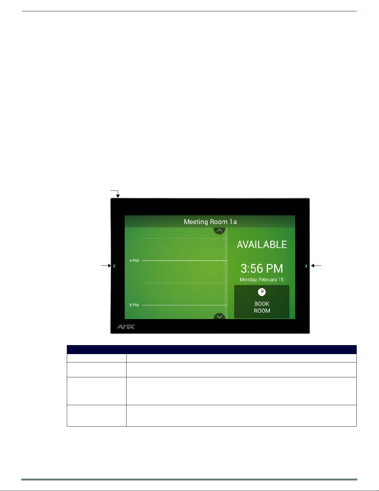
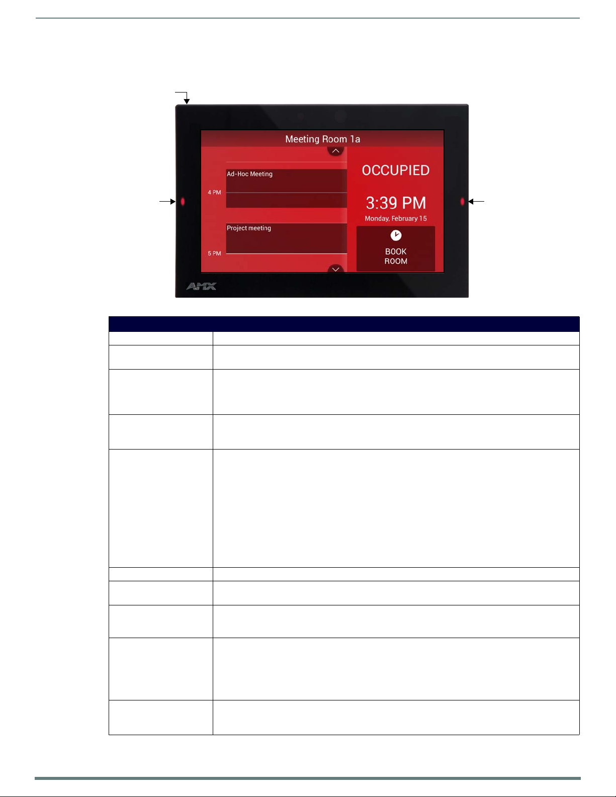
Room Status Room Status
LED LED
Pushbu tton
AMX RoomBook Scheduling Touch Panels
Overview
The RMBK-1001, 10.1” AMX RoomBook Scheduling Touch Panel (FG2265-40) and RMBK-701, 7” AMX RoomBook Scheduling
Touch Panel (FG2265-37) are standalone touch panels that integrate directly with popular room scheduling software like Microsoft
Exchange, Office 365 and Google Calendar without additional system hardware requirements. The user interface background color
and built-in room availability bars change between red and green to show room availability so users can easily locate and book an
available room directly from the panel and, if that room is currently booked, users can quickly locate the nearest available room or
the next available time with ease.
Leveraging the style and cost-efficiency of our award winning Modero S Series Touch Panel, AMX RoomBook Scheduling Touch
Panels include SmoothTouch™ Technology, a brilliant full-color high-resolution display, wide viewing angle of screen and availability
bar LEDs, and a low profile design for a subtle aesthetic. The RMBK-1001/701 can be mounted on any flat surface, including glass
or stone, inside or outside a conference room or classroom.
Acendo Book panels are easy to install using a one-time, panel-based configuration wizard, to get the panel operational in a matter
of minutes with minimal training.
NOTE: For end-user instructions on using the Acendo Book panels once they are installed and configured, refer to the Acendo Book
Scheduling Panels - User Guide section on page 65.
RMBK-1001
The RMBK-1001, 10.1” AMX RoomBook Scheduling Touch Panel is shown in FIG. 1:
FIG. 1
RMBK-1001, 10.1” AMX RoomBook Scheduling Touch Panel
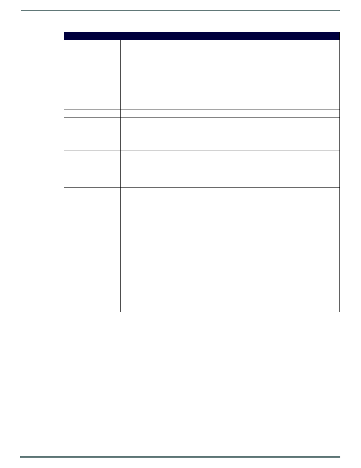
RMBK-1001 Product Specifications
DIMENSIONS (HWD): 6 13/16" x 10 1/16" x 2" (174 mm x 255 mm x 51 mm)
WEIGHT: • 1.95 lbs (.885 Kg), with back box
• 1.5 lbs (.680 Kg), without back box
POWER CONSUMPTION: • Full-On: 14.5 W (max)
•Typical: 7.5 W
•Standby: 4.7 W
• Shutdown: 0.8 W
EXTERNAL POWER SUPPLY
REQUIRED
Optimal performance requires use of one of the following AMX PoE power supplies (not included):
• PS-POE-AF-TC, PoE Injector, 802.3AF Compliant (FG423-83)
• NXA-ENET8-2POE, Gigabit PoE Ethernet Switch (FG2178-63)
AMX RoomBook Scheduling Touch Panels
10
AMX RoomBook Scheduling Touch Panels - Instruction Manual
RMBK-1001 Product Specifications (Cont.)
TOUCH SCREEN DISPLAY • Display Type: TFT Active Matrix Color LCD with Fringe Field Switching (FFS) - Wide Viewing Angle
VIEWING ANGLE 85°/85°/85°/85° (Up/Down/Left/Right)
MEMORY • SDRAM: 1 GB
COMMUNICATIONS Ethernet: 10/100 Mbits/s (full duplex) Auto MDI-X, RJ-45 connector. Supported IP and IP-Based Protocols:
FRONT PANEL
COMPONENTS
CONNECTIONS • Ethernet: 10/100 port, RJ-45 connector
SUPPORTED LANGUAGES •
CERTIFICATIONS • FCC Part 15 Class A
OPTIONAL ACCESSORIES • MXSA-REM-TL, Panel Removal Tool (FG5968-99)
Technology
• Display Size (WH): Landscape: 9.1" x 5.9" (230 mm x 149 mm), 10.8" (274 mm) diagonal
• Viewable Area (WH): Landscape: 8.5" x 5.4" (217 mm x 136 mm ), 10.0" (256 mm) diagonal
• Resolution: Landscape: 1280x800
• Aspect Ratio: Landscape: 16:9
• Brightness: 350 cd/m2
• Contrast Ratio: 800:1
• Color Depth: 16.7M colors
• Illumination: LED
•Touch Overlay: Resistive
•Flash: 16 GB
UCP, TCP, ICMP, DHCP, SSH (support the use of inbound SSH (Secure Shell) protocol communications when
the SSH feature is enabled).
• Room Status LEDs: 2 red/green LEDs on either side of the panel indicate the current room status
(green = available, red = occupied). Note that these LEDs can be disabled via options on the Room setup
page (see the Setup Wizard: Step 6 - ROOM section on page 31).
• Recessed Settings pushbu tton (located on the left top edge) provides access to the SETTINGS window. To
open the SETTINGS window, use a paper-clip or similar tool to press and hold the pushbutton for 5
seconds. See the Accessing the SETTINGS Window section on page 13 for details.
• USB: (1) USB host 2.0, type A port
• Power: PoE (Power over Ethernet), 802.3af, class 0
• C-Tick CISPR 22 Class A
• CE EN 55022 Class A and EN 55024
•IEC/EN-60950
•UL 60950-1
• RoHS/WEEE compliant
• MSA-AMK2-10, Any Mount Kit for 10.1" Modero S Series and Acendo Book Touch Panels (FG2265-36)
• MSA-MMK2-10, Multi Mount Kit, 10.1" Modero S Series and Acendo Book Touch Panels (FG2265-21)
• PS-POE-AF-TC, PoE Injector, 802.3AF Compliant (FG423-83)
• NXA-ENET8-2POE, Gigabit PoE Ethernet Switch (FG2178-63)
• CB-MSA-10, Rough-In Box and Cover Plate for 10.1" Modero S Series Wall Mount Touch Panel
(FG2265-08)
• MSA-RMK-10, Rack Mount Kit for 10" Modero S Series Wall Mount Touch Panel (FG2265-14)
• MXA-CLK, Modero X/S Series Cleaning Kit (FG5968-16)
11
AMX RoomBook Scheduling Touch Panels - Instruction Manual
RMBK-701
Room Status Room Status
LED LED
Pushbu tton
The RMBK-701, 7” AMX RoomBook Scheduling Touch Panel is shown in FIG. 2:
FIG. 2
RMBK-701, 7” AMX RoomBook Scheduling Touch Panel
AMX RoomBook Scheduling Touch Panels
RMBK-701 Product Specif ications
DIMENSIONS (HWD): 4 7/8" x 7 3/8" x 2 1/4" (123.9 mm x 187.5 mm x 58 mm)
WEIGHT: • 1.05 lbs (.680 Kg), with back box
• 0.8 lbs (.363 Kg), without back box
POWER CONSUMPTION: • Full-On: 11 W (max)
•Typical: 7.5 W
•Standby: 4.5 W
• Shutdown: 0.7 W
EXTERNAL POWER SUPPLY
REQUIRED
TOUCH SCREEN DISPLAY • Display Type: TFT Active Matrix Color LCD with Fringe Field Switching (FFS) - Wide Viewing Angle
VIEWING ANGLE 89°/89°/89°/89° (Up/Down/Left/Right)
MEMORY • SDRAM: 1 GB
COMMUNICATIONS Ethernet: 10/100 Mbits/s (full duplex) Auto MDI-X, RJ-45 connector. Supported IP and IP-Based
FRONT PANEL COMPONENTS • Room Status LEDs: 2 red/green LEDs on either side of the panel indicate the current room status
CONNECTIONS • Ethernet: 10/100 port, RJ-45 connector
Optimal performance requires use of one of the following AMX PoE power supplies (not included):
• PS-POE-AF-TC, PoE Injector, 802.3AF Compliant (FG423-83)
• NXA-ENET8-2POE, Gigabit PoE Ethernet Switch (FG2178-63)
Technology
• Display Size (WH): Landscape: 7.3" x 4.8" (186 mm x 122 mm), 8.8" (222 mm) diagonal
• Viewable Area (WH): Landscape: 6.05" x 3.54" (154 mm x 90 mm), 7.0" (178 mm) diagonal
• Resolution: Landscape: 1024x600
• Aspect Ratio: Landscape: 16:9
• Brightness: 400 cd/m2
• Contrast Ratio: 800:1
• Color Depth: 16.7M colors
• Illumination: LED
•Touch Overlay: Resistive
•Flash: 16 GB
Protocols: UCP, TCP, ICMP, DHCP, SSH (support the use of inbound SSH (Secure Shell) protocol
communications when the SSH feature is enabled)
(green = available, red = occupied). Note that these LEDs can be disabled via options on the Room setup
page (see the Setup Wizard: Step 6 - ROOM section on page 31).
• Recessed Settings pushbutton (located on the left top edge) provides access to the SETTINGS window.
To open the SETTINGS window, use a paper-clip or similar tool to press and hold the pushbutton for 5
seconds. See the Accessing the SETTINGS Window section on page 13 for details.
• USB: (1) USB host 2.0, type A port
• Power: PoE (Power over Ethernet), 802.3af, class 0
AMX RoomBook Scheduling Touch Panels
12
AMX RoomBook Scheduling Touch Panels - Instruction Manual
RMBK-701 Product Specif ications (Cont.)
CERTIFICATIONS • FCC Part 15 Class A
• C-Tick CISPR 22 Class A
• CE EN 55022 Class A and EN 55024
•IEC/EN-60950
•UL 60950-1
• RoHS/WEEE compliant
OPTIONAL ACCESSORIES • MXSA-REM-TL, Panel Removal Tool (FG5968-99)
• MSA-AMK2-07 Any Mount Kit for 7" Modero S Series and Acendo Book Touch Panels (FG2265-35)
• MSA-MMK2-07, Multi Mount Kit for 7" Modero S Series and Acendo Book Touch Panels (FG2265-22)
• PS-POE-AF-TC, PoE Injector, 802.3AF Compliant (FG423-83)
• NXA-ENET8-2POE, Gigabit PoE Ethernet Switch (FG2178-63)
• CB-MXSA-07, Rough-In Box and Cover Plate for the 7" Wall Mount Modero X/S Series Touch Panels
(FG039-18)
• MSA-RMK-07,Rack Mount Kit for Modero S Series Touch Panel, 7" (FG2265-15)
• MXA-CLK, Modero X/S Series Cleaning Kit (FG5968-16)
Supported Scheduling Systems
Acendo Book Scheduling Panels support the following scheduling systems: Microsoft Exchange, Off ice 365 and Google Calendar.
The following table indicates the specific versions of each scheduling system that was tested and verified:
Supported Scheduling Systems
Microsoft Exchange • Exchange 2010 SP3 (Microsoft Exchange Server 2010 Service Pack 3)
• Exchange 2013 CU11 (Cumulative Update 11 for Exchange Server 2013)
• Exchange 2016 RTM
Office 365 Office 365 Business Premium and Exchange Online (Plan 1)
Google Cale ndar Google Apps for Work
Conf iguring Acendo Book Touch Panels
Initial Panel Conf iguration (Scheduling Panel Setup Wizard)
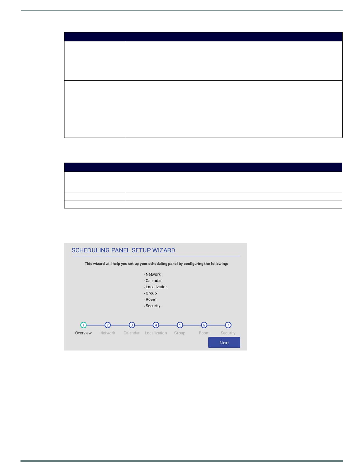
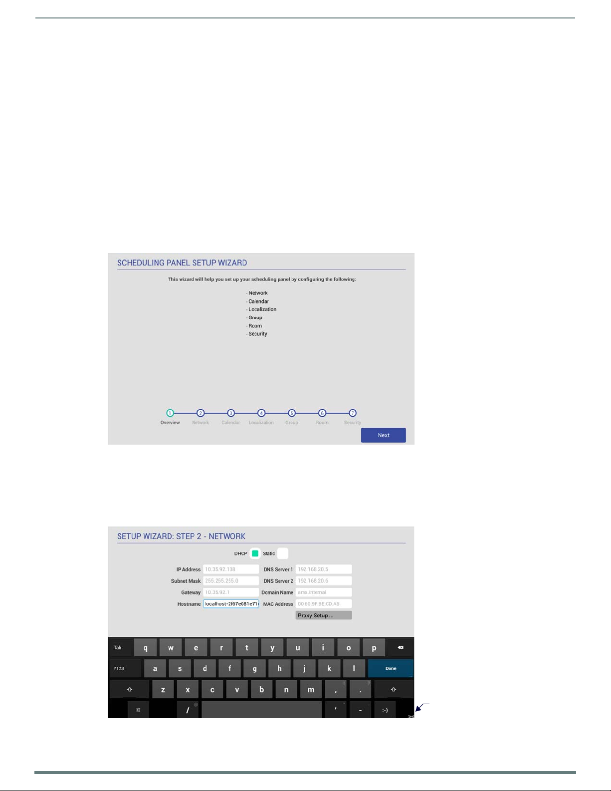
The initial conf iguration for Acendo Book panels is easily accomplished using the Scheduling Panel Setup Wizard (FIG. 3):
FIG. 3 Scheduling Panel Setup Wizard
The Scheduling Panel Setup Wizard is automatically launched the first time the Acendo Book panel is powered up. This wizard steps
you through the process of conf iguring network/communications settings for the touch panel, and presents required configuration
options for the selected calendar system. See the Using the Scheduling Panel Setup Wizard section on page 22 for details on initial
setup and configuration.
AMX RoomBook Scheduling Touch Panels
13
AMX RoomBook Scheduling Touch Panels - Instruction Manual
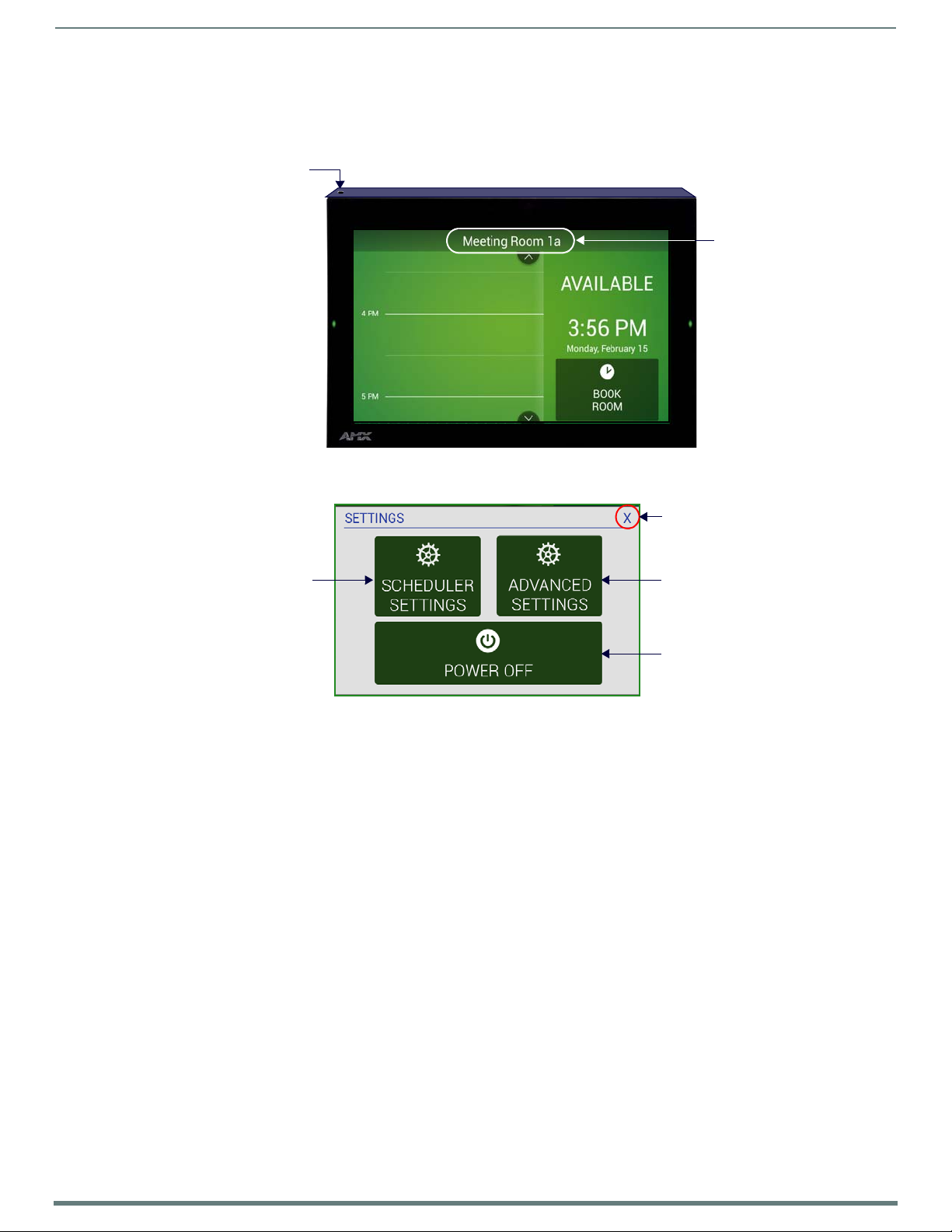
Recessed pushbutton
located here
Press and hold for
5 seconds to access
the SETTINGS window
press and hold the Room Name
title bar for 5 seconds to access
the SETTINGS window
Alternatively,
Press to close the SETTINGS window
Press to access the panel’s on-board
Settings menu (Administrator password
Press to access the
Scheduler Settings pages
Press to power the panel off
requ ired - default = 1988)
Accessing the SETTINGS Window
Scheduler Settings and Advanced Settings are both accessed via the SETTINGS window on the Acendo Book panel.
To invoke the SETTINGS window, use a paper-clip or similar tool to press and hold the recessed Settings pushbutton located on the
top edge of the panel (left side - see FIG. 4) for 5 seconds.
FIG. 4
Pushbutton - Located on the top edge of the panel (left side)
Alternatively, A long press of the room name (5 seconds minimum), will also invoke the SETTINGS window.
FIG. 5 SETTINGS window
Acendo Book touch panels have two sets of conf iguration options: Scheduler Settings, and Advanced Settings:
NOTE: Scheduler Settings and Advanced Settings are both password-protected. The default Administrator password is "1988". The
Administrator password can be changed via options in the Security Setup page - see Changing the Administrator Password on the
Panel on page 33 for details.
Conf iguring Scheduler Settings
While the initial configuration for Acendo Book panels is managed via the Scheduling Panel Setup Wizard (FIG. 3 on page 12), most
of the settings made in the Scheduling Panel Setup Wizard can be edited via the Scheduler Settings pages.
Press SCHEDULER SETTINGS in the SETTINGS window to open the Scheduler Settings pages. Refer to the Scheduler
Settings section on page 35 for details.
Conf iguring Touch Panel Settings
ADVANCED SETTINGS are used to configure settings for the touch panel itself. Touch panel-specif ic settings can be viewed and
edited via the ADVANCED SETTINGS option.
Press ADVANCED SETTINGS in the SETTINGS window, and enter the Administrator password to access the panel’s on-board
Settings menu. Refer to the Advanced Settings section on page 42 for information on viewing/edit touch panel-specific options.
Powering Off the Panel
Note that the SETTINGS window also provides the option to gracefully power down the touch panel.
Press POWER OFF to power down the panel.
Cleaning the Touch Panel
When cleaning th e device, do not directly spray th e device with cleaning fluid. Instead, spray the cloth and then apply the cloth to
the touch screen.
CAUTION:
finish.
Do NOT use abrasives of any type to clean the device, as abrasives may permanently damage or remove the device’s
14
AMX RoomBook Scheduling Touch Panels - Instruction Manual
Installation
AMX DEVICE
T2
T1
FILLED OR CLOSED
VOLUME, LIMITED OR
NO CONVECTION
T1, T2 < TOpMax
T1, T2 > TOpMin
T1
AMX DEVICE
T3
T4
T2
RACK MOUNTED DEVICES
T1, T2, T3, T4 < TOpMax
T1, T2, T3, T4 > TOpMin
Overview
Acendo Book Scheduling (wall mount) Touch Panels can be installed via several mounting options:
Use the included clear plastic Backbox to attach the panel to most standard wall materials.
Other optional AMX mounting solutions include the MSA-MMK-xx Multi Mount Kit, the MSA-AMK-xx Any Mount Kit, and the
CB-MXSA-xx Rough-In Box. Refer to the Quick Start Guide included with each mounting kit for instructions.
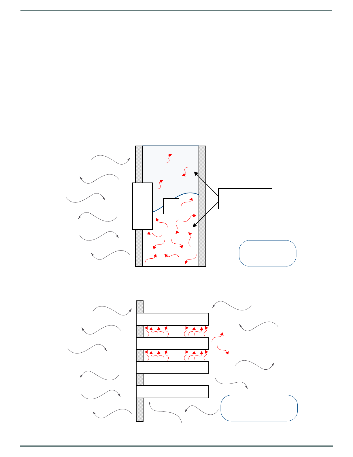
A Note About Wall and Rack Installation
Some products are installed in areas of differing temperature and cooling methodologies. These include products installed in walls,
racks, cabinets, etc. Those areas may have different temperatures and/or cooling approaches that must be taken into consideration
to maintain the product within the specif ied operating temperature.
FIG. 6 shows an AMX device installed in a wall with a filled volume (such as with insulation or concrete), as well as with a closed
volume (such as between studs in an otherwise f inished wall). The diagram shows how heat generated by the device or other
devices may have no way to escape, and may build up to levels that may affect device operation.
Acendo BookInstallation
FIG. 6
Heat convection in filled or closed volume, limited or no convection
In F IG. 7, the diagra m displays an AMX device in a typical rack mounting, with full air circulation around the front and back of the
device. In this case, the main concern is with heat building up between components, possibly to levels that may affect device
operation.
FIG. 7 Heat convection in rack-mounted devices
Acendo BookInstallation
15
AMX RoomBook Scheduling Touch Panels - Instruction Manual
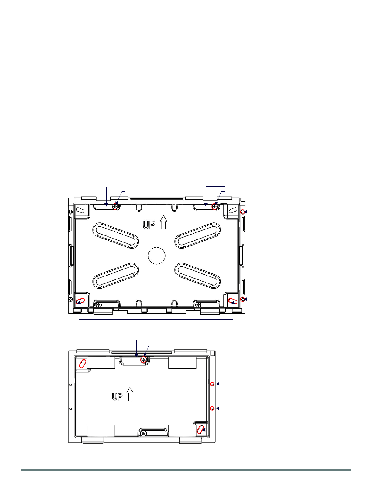
Locking Tab (X4)
Locking Tab screw (x4)
Mounting holes (X4) for installing the Backbox into a Rough-In Box (screws not included)
Mounting holes (X4) for use with
Use these mounting holes to install
Locking Tab (X4)
Locking Tab screw (x4)
mounting screws (not included)
the Backbox into thin walls (less
than 0.5” thick) or solid surfaces
Locking Tab (X2)
Locking Tab screw (x2)
Mounting holes (X4) for use with
Use these mounting holes to install
mounting screws (not included)
the Backbox into thin walls (less
than 0.5” thick) or solid surfaces
Mounting holes (X2) for installing the Backbox
into a Rough-In Box (screws not included)
Installation Recommendations
During any installation, a lack of ventilation may produce conditions that may adversely affect the device’s operation. In these
circumstances, special care must be made to make sure that temperatures within enclosed areas do not exceed the device’s
maximum rated temperature.
NOTE: While the outside temperature of the device may be at or below its maximum operating temperature, special care must be
taken before and during installation to ensure that the maximum operating temperature is not exceeded within wall or rack
installation spaces.
Mounting Options
AMX RoomBook Scheduling Touch Panels can be installed via several mounting options:
Use the included clear plastic Backbox to attach the panel to most standard wall materials.
Other optional AMX mounting solutions include the MSA-MMK2-07/10 Multi Mount Kits, and the MSA-AMK2-07/10 Any Mount
Kits, and CB-MXSA-07/10 Rough-In Boxes. Refer to the Quick Start Guide included with each mounting kit for instructions.
Power Over Ethernet
Power for AMX RoomBook Scheduling Touch Panels is supplied via Power Over Ethernet (PoE), utilizing an AMX-certified PoE
injector such as the PS-POE-AF-TC PoE Injector (FG423-83). The incoming Ethernet cable should be connected to the RJ-45 port
on the RMBK-701/1001.
Plastic Backbox
AMX RoomBook Scheduling Touch Panels come with a clear plastic Backbox. This Backbox can be used to mount the touch panel
into most standard wall materials. The Backbox can also used to mount the panel into other mounting options.
FIG. 8 RMBK-1001 Backbox (Front View)
FIG. 9 RMBK-701 Backbox (Front View)
Acendo BookInstallation
16
AMX RoomBook Scheduling Touch Panels - Instruction Manual
FOR REFERENCE ONLY
FOR REFERENCE ONLY
NOTE: For typical mounting surfaces, such as drywall, use the locking tabs as the primary method for securing the Backbox to the
surface. For thin walls or solid surfaces, use mounting screws (not included).
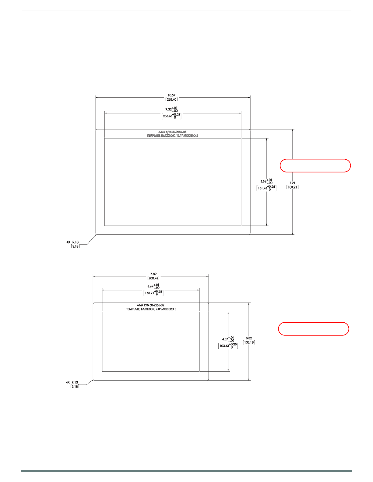
STEP 1: Install the Plastic Backbox
Use the included Installation Template to determine the placement of the Backbox in the mounting surface. The outside edges of
the template are the same dimensions as the touch panel, which allows you to troubleshoot possible conflicts with wall edges,
doors, and other potential obstacles.
NOTE: Prepare the area by removing any screws or nails from the drywall before beginning the cutout process.
MXD-1001-L - Template, Backbox, 10.1" Touch Panel, Modero S Series (68-2265-03)
FIG. 10
FIG. 11 S Series Installation Templates
1. After ensuring proper placement, cut an opening in the mounting surface for the Backbox, using the included Installation
S Series Installation Templates
MXD-701-L - Template, Backbox, 7.0" Touch Panel, Modero S Series (68-2265-02)
The templates are marked to ensure that the touch panel and Backbox are properly aligned.
Temp lat e as a g uid e.
NOTE: When installing the Backbox, make sure that the assembly is in the correct position and in the correct place. Once the
locking tabs are extended and locked into place, removing the Backbox may be difficult without having access to the back of the
wall or causing damage to the wall.
Acendo BookInstallation
17
AMX RoomBook Scheduling Touch Panels - Instruction Manual
Locking Tab screws (x4) -
Locking Tab
tighten to extend each of
the four Locking Tabs
(max torque = 5 IN-LB)
(front) (rear)
Locking Tab
Locking Tab
Locking Tab
(front)
Locking Tab screws (x4) -
tighten to extend each of
the four Locking Tabs
(max torque = 5 IN-LB)
Locking Tab
Locking Tab
(rear)
NOTE: Consider making the actual cutout opening slightly smaller than the provided dimensions. This provides a margin of error
if the opening needs to be expanded. Too little wall material removed is always better than too much.
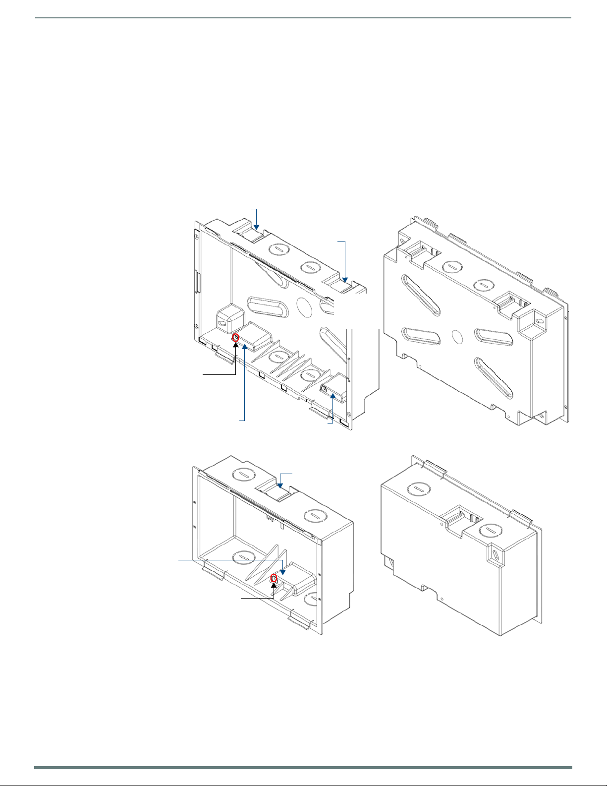
2. Thread the incoming cables (Ethernet and Micro-USB) from their terminal locations through the surface opening, leaving
enough slack in the wiring to accommodate any re-positioning of the panel.
3. Remove the Backbox knockouts and thread incoming cables through the knockout holes.
4. Gently push the Backbox into the mounting surface.
This Backbox uses two Locking Tabs to secure the Backbox to the wall. For typical mounting surfaces, such as drywall, the
locking tabs are the primary method for securing the Backbox to the wall.
To ensure a stable installation, the thickness of the wall material must be a minimum of .50 inches (1.27cm) and a
maximum of .875 inches (2.22cm). The mounting surface should also be smooth and flat. For thin walls or solid surfaces,
use mounting screws (not included) - see FIG. 8.
5. Extend the Locking Tabs by tightening the Locking Tab screws until snug.
FIG. 12 and FIG. 13 show the Locking Tabs on the RMBK-1001 and RMBK-701 Backboxes:
FIG. 12
RMBK-1001 Backbox - Locking tab and locking tab screws (X4)
FIG. 13 RMBK-701 Backbox - Locking tab and locking tab screws (X2)
CAUTION:
The maximum recommended torque to screw in the locking tabs on the plastic Backbox is 5 IN-LB [56 N-CM].
Excessive torque on the tab screws can strip out the locking tabs or damage the Backbox.
Extend the Locking Tabs only AFTER the Backbox is inserted into the wall.
When installing the Backbox, make sure that it is positioned correctly.
The Backbox is clear to allow visual conf irmation that the tabs have been extended and are gripping the wall, as well as in
assisting with removal if necessary.
Acendo BookInstallation
18
AMX RoomBook Scheduling Touch Panels - Instruction Manual
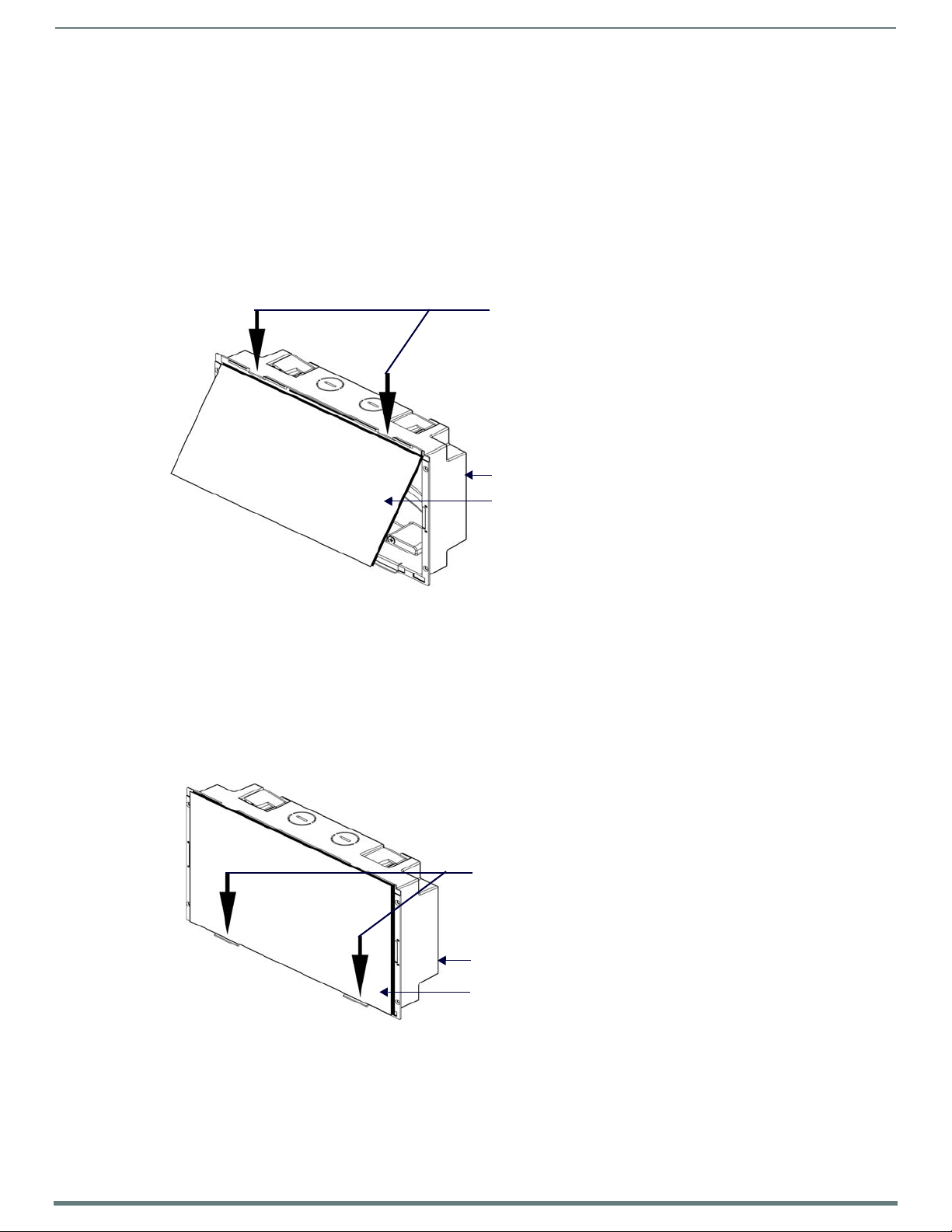
Use the top-hooks on the top edge of the
Plastic Backbox
RMBK-1001 Touch Panel
Backbox to latch the top of the touch
panel into place
Gently press the bottom edge of the
touch panel in these places (simultaneously)
to snap the bottom edge of the panel into
place and secure the panel in the Backbox
SEE NOTES BELOW
Observe the decal that is placed on the touch
panel (glass surface) to avoid pressing the glass
Plastic Backbox
RMBK-1001 Touch Panel
in the wrong places, which could result in
dama ge to the panel
STEP 2: Insert Connectors on the Touch Panel
1. Before installing the touch panel into the Backbox, connect the Ethernet and USB cables to the rear of the panel.
2. Remove power at the terminal end before continuing with the installation.
NOTE: Do not disconnect the connectors from the touch panel. The panel must be installed with the connectors attached before
being inserted into the mounting surface.
STEP 3: Secure the Touch Panel To the Backbox
The Backbox uses notches and tabs on the front edges (top and bottom) to secure the panel into place. Follow the steps below to
install the panel into the Backbox, starting the upper edge of the touch panel:
UPPER TABS FIRST
1. Center the top edge of the touch panel against the upper outside edge of the Backbox and latch the top of the panel onto the
Backbox top-hooks (FIG. 14):
FIG. 14
2. Gently press the top edge of the touch panel into place to engage the panel’s notches and the top-hooks on the Backbox.
Engaging the top edge of the panel with the top hooks on the Backbox
LOWER TABS - Gently Snap Into Place
1. Swing the bottom edge of the touch panel into position until it rests against the lower outside edge of the Backbox.
NOTE: If a gap is observed between the panel and the Backbox, or binding is felt while locking down the panel, stop and verify
there are no cables in the way. Do not force the panel into position, or the touch screen or the panel electronics may be
damaged.
2. Gently press the bottom edge of the panel gently but f irmly and ONLY IN THE PLACES INDICATED BELOW until the tabs click
into place to secure the panel (FIG. 15):
FIG. 15 SNAPPING THE BOTTOM EDGE OF THE PANEL INTO THE BACKBOX
3. Reconnect the terminal Ethernet and USB to their respective locations on either the Ethernet port.
Acendo BookInstallation
19
AMX RoomBook Scheduling Touch Panels - Instruction Manual
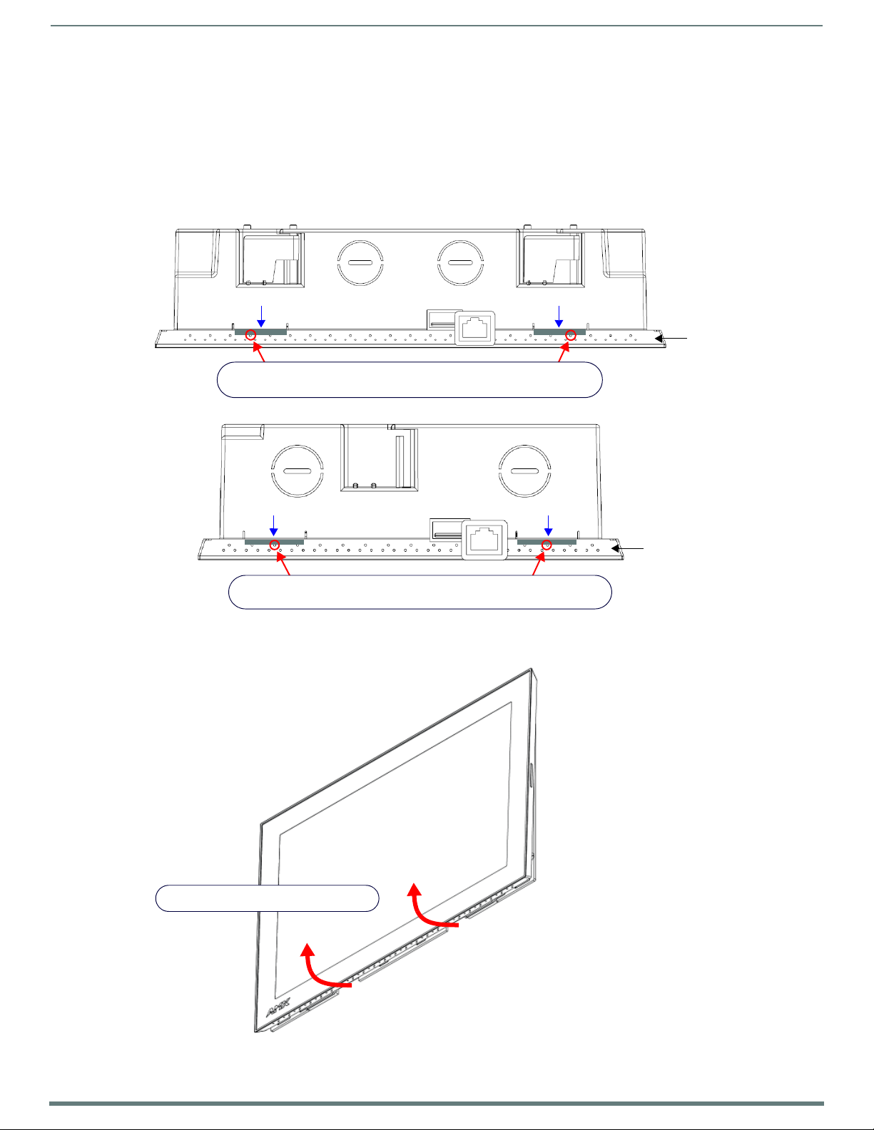
Bottom Clip Bottom Clip
Insert probe (or Bezel Removal Tool) straight into access holes to push
the bottom clips in and away from the panel to release the bottom edge
Bezel (bo ttom edge)
Bottom Clip Bottom Clip
Insert probe (or Bezel Removal Tool) straight into access holes to push
the bottom clips in and away from the panel to release the bottom edge
Bezel (bottom edge)
Lift the bottom edge of the panel by the plastic bezel
and gently rotate up and away from the Backbox
Note: To avoid damaging the panel, always pull on the plastic bezel - do not pull on the glass.
Note: Hold the panel to prevent it from falling once the bottom edge is free
Removing the RMBK-1001/701 Panel from the Backbox
The tabs on the bottom edge of the Backbox lock down the RMBK-1001 and must be unlatched in order to remove the touch panel
from the Backbox. To do this, you ll need a thin probe such as an straightened paper clip, or the (optional) MXSA-REM-TL Bezel
Removal Tool:
NOTE: The (optional) MXSA-REM-TL, Bezel Removal Tool (FG5968-99) provides a convenient method to release these clips. The Bezel
Removal Tool makes it easy to locate the appropriate release points for each panel size. Refer to the MXSA-REM-TL Quick Start Guide
for details.
1. With a thin probe, carefully press straight into the access holes on the bottom of the bezel (near the center of the bottom
tabs) to disconnect the two bottom clips (FIG. 16, FIG. 17) .
.
FIG. 16
RMBK-1001/Backbox assembly
FIG. 17 RMBK-701/BACKBOX ASSEMBLY - BOTTOM VIEW
2. Grasp the bottom of the panel and pull gently outward until the side of the panel is free of the snap. Use your other hand to
stabilize the front of the touch panel (FIG. 18):
FIG. 18 RMBK-1001/BACKBOX ASSEMBLY (RELEASING THE BOTTO M EDGE OF THE PANEL )
Acendo BookInstallation
20
AMX RoomBook Scheduling Touch Panels - Instruction Manual
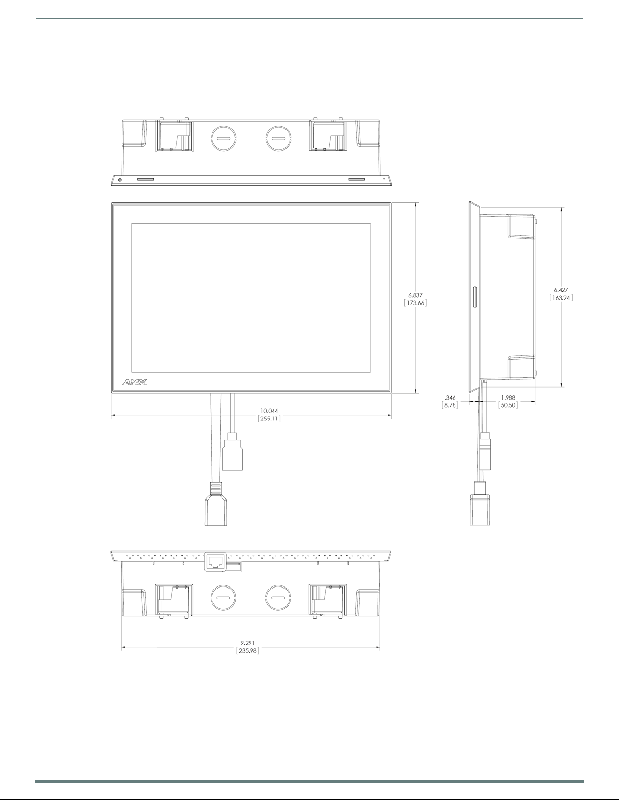
Notes:
Dimensions in parenthesis are in millimeters
Additional detailed installation and product drawings
are available to view/download at www.amx.com
USB port
Ethernet port
NOTE: Always pull on the frame of the touch panel. NEVER pull on the glass edge.
3. With the bottom edge of the panel free, carefully lift up and out to release the tabs on the top edge of the panel.
Installation Dimensions
RMBK-1001 Dimensions
FIG. 19
RMBK-1001
Detailed specifications d rawings for the RMBK-1001 are available to download from www.amx.com.
21
AMX RoomBook Scheduling Touch Panels - Instruction Manual
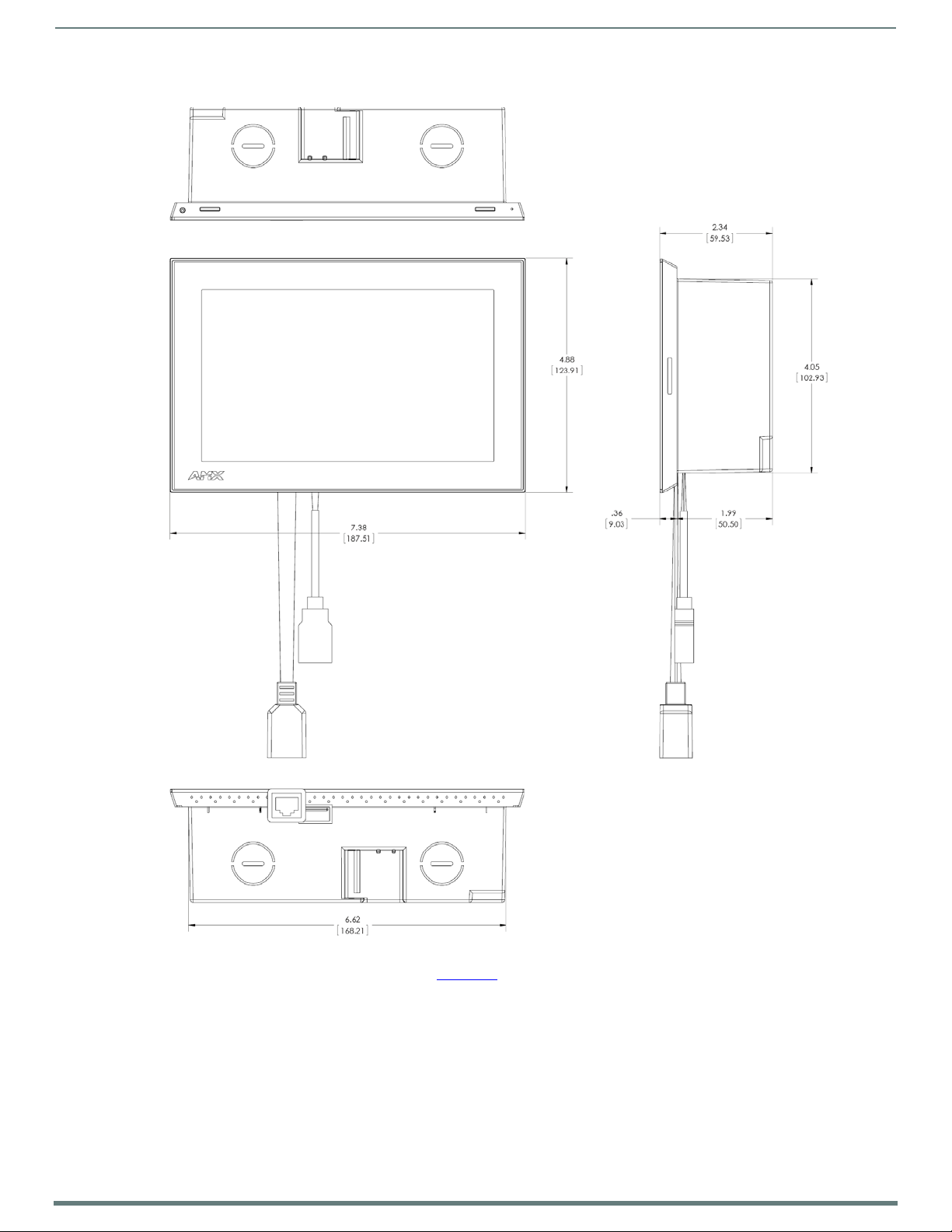
RMBK-701 Dimensions
Notes:
Dimensions in parenthesis are in millimeters
Addition al detai led installation and pro duct drawings
are available to view/download at www.amx.com
USB port
Ethernet port
Acendo BookInstallation
FIG. 20
RMBK-701
Detailed specifications d rawings for the RMBK-701 are available to download from www.amx.com.
Using the Scheduling Panel Setup Wizard
22
AMX RoomBook Scheduling Touch Panels - Instruction Manual
Press to close the on-screen keyboard
Using the Scheduling Panel Setup Wizard
Overview
Acendo Book Scheduling Panels are easy to set up using the Scheduling Panel Setup Wizard - a one-time, panel-based configuration
wizard to get the panels operational in a matter of minutes with minimal training. The Scheduling Panel Setup Wizard is
automatically launched the f irst time the Acendo Book panel is powered on. This section describes each of the screens presented in
the Scheduling Panel Setup Wizard.
NOTE: The Scheduling Panel Setup Wizard will be launched again if "Factory Data Reset" or "Reset Settings" is performed on the
panel (via Advanced Settings options; see SYSTEM - Reset and Update on page 60 for details).
Press the Next button in each Wizard page to save changes and proceed to the next page.
Note that these settings can be changed later via the Settings pages (see the Scheduler Settings section on page 35 for
details).
Setup Wizard: Step 1 - OVERVIEW
The Overview page presents a summary of the steps that entail the Scheduling Panel Setup Wizard (FIG. 21):
FIG. 21
Review this information and press Next to proceed (to the Network page).
Scheduling panel Setup Wizard - Overview page
Using the On-Screen Keyboard/Keypad
When each Setup Wizard page opens, the cursor is automatically placed in the first editable text field on the page and the onscreen keyboard or keypad is opened to allow editing of the active field. The example in FIG. 22 shows the NETWORK page with the
cursor in the Hostname field (the f irst and only editable field in this example) and the on-screen keyboard displayed:
FIG. 22 On-Board Keyboard (Network page)
Using the Scheduling Panel Setup Wizard
23
AMX RoomBook Scheduling Touch Panels - Instruction Manual
Press to close the on-screen keypad
Press move the cursor to
the next editable field
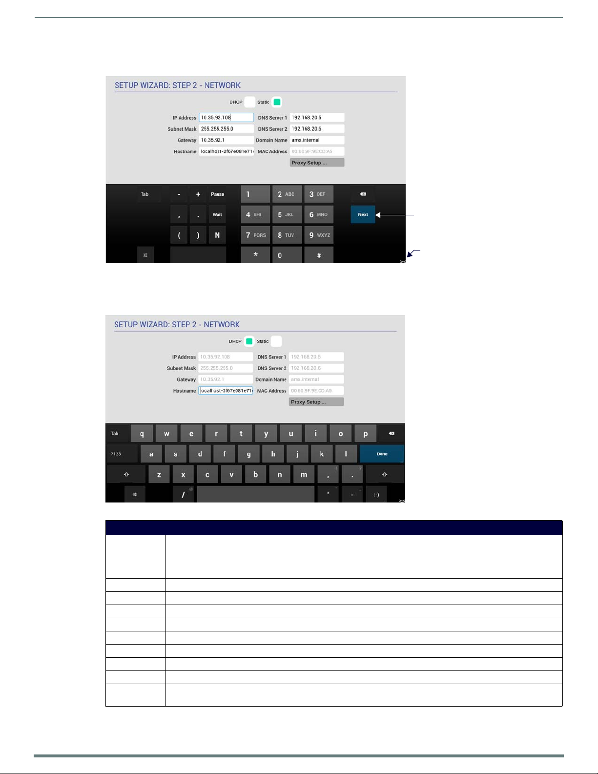
Note that if the selected field requires numeric entry, the on-screen keypad is opened instead. The example in FIG. 23 shows the
cursor in the IP Address field, and the on-screen keypad displayed:
FIG. 23
On-Board Keypad (Network page)
Setup Wizard: Step 2 - NETWORK
Use the options in the NETWORK page to configure the scheduling panel’s connection to the network (FIG. 24):
FIG. 24 Setup Wizard: Step 2 - NETWORK
Setup Wizard - NETWORK page options
DHCP/Static Select how to assign an IP Address to this panel:
• DHCP (default setting): Select this option to use DHCP to automatically assign an IP address to the panel. Note that
when DHCP is selected, the other f ields on this page are disabled.
• Stat ic: Select to manually configure the IP address for this panel using the f ields provided on this page.
IP Address Enter a valid IP Address for this panel.
Subnet Mask Enter a valid Subnet Mask address for this panel (as required).
Gateway Enter a valid Gateway address for this panel (as required).
Hostname Enter a valid Hostname for this panel (as required).
DNS Server 1 Enter a valid DNS Server #1 address for this panel (as required).
DNS Server 2 Enter a valid DNS Server #2 address for this panel (as required).
Domain Name Enter a valid Domain Name for this panel (as required).
MAC Address This read-only f ield provides the MAC Address associated with this panel.
Proxy Setup Press to conf igure this scheduling panel to connect to a proxy server (only if necessary), via options in the Proxy
Settings page. For information on Proxy Settings, refer to the Proxy Setup section on page 37.
Using the Scheduling Panel Setup Wizard
24
AMX RoomBook Scheduling Touch Panels - Instruction Manual
Fill in these fields and press Next to proceed (press Back to return to the OVERVIEW page).
NOTE: These settings can be changed later if necessary, via the NETWORK Settings page (see Viewing/Editing Network Settings on
page 36).
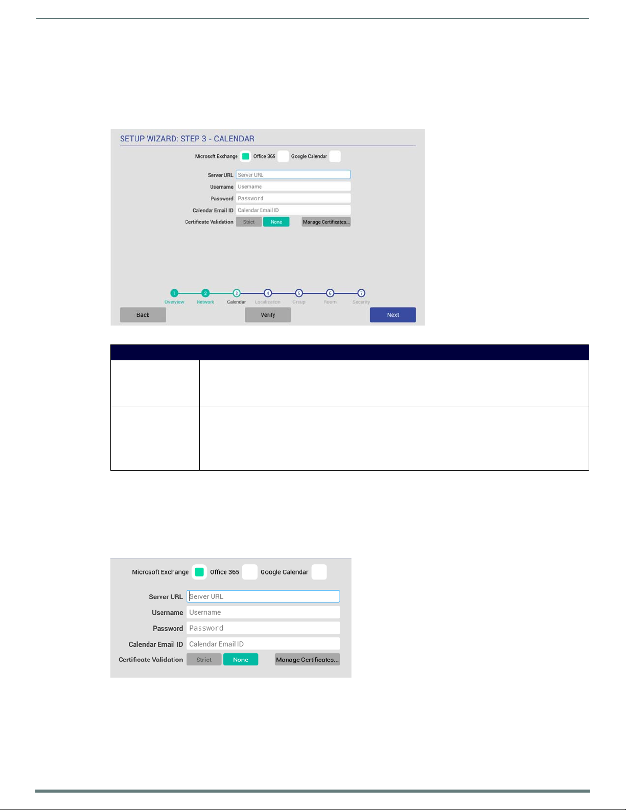
Setup Wizard: Step 3 - CALENDAR
Use the options in the CALENDAR page to configure the scheduling panel’s connection to the scheduling system (FIG. 25):
FIG. 25
Setup Wizard: Step 3 - CALENDAR (Microsoft Exchange options shown)
Setup Wizard - CALENDAR page options
Calender Type Selection Select the scheduling system that this panel will use:
• Microsoft Exchange (see page 24)
• Office 365 (see page 25)
• Google Calendar (see page 26)
Verify Press to verify that the scheduling panel can connect to the scheduling system using the information
currently entered on this page.
The system will indicate whether or not is is able to connect to the calendar system using the current settings
(see FIG. 27 on page 25). If the panel fails to connect, review all information entered on the Calendar page and
try again.
Note that the Next button remains disabled until the calendar settings have successfully been verified.
Calendar Types
Use the Calendar Type Selection options at the top of the CALENDAR page to specify the scheduling system that this panel will use.
This selection will invoke configuration settings specific to the selected Calendar type, as described below:
Microsoft Exchange
To conf igure the Acendo Book Panel for use with Microsoft Exchange:
1. In the Setup Wizard: Step 3 - Calendar page, select Microsoft Exchange to invoke the following options (FIG. 26) :
FIG. 26 Microsoft Exchange Calendar Configuration Settings
Using the Scheduling Panel Setup Wizard
25
AMX RoomBook Scheduling Touch Panels - Instruction Manual
Microsoft Exchange Calendar Configuration Settings
Server URL Enter the full URL for the scheduling server.
Example syntax:
https://<EXCHANGE_SERVER_HOSTNAME>/EWS/Exchange.asmx
Username Enter the Username (including domain) required to login to the scheduling server (as required).
Example: "JaneDoe@acme.onmicrosoft.com".
Password Enter the Password required to login to the scheduling server (as required).
Calendar Email ID Enter the Email ID (including domain) used by the scheduling service.
Example: "ConfRoom1@acme.onmicrosoft.com"
Certificate Validation • Select Stri ct to xxxxxx xxx xxx xxxxxxx.
• Select None to xxxxxx xxx xxx xxxxxxx.
• Select Manage Certif icates to open the Security (Advanced Settings) page (see FIG. 100 on page 56),
which provides access to Credential Storage options, as described in the Installing Certificates section on
page 59.
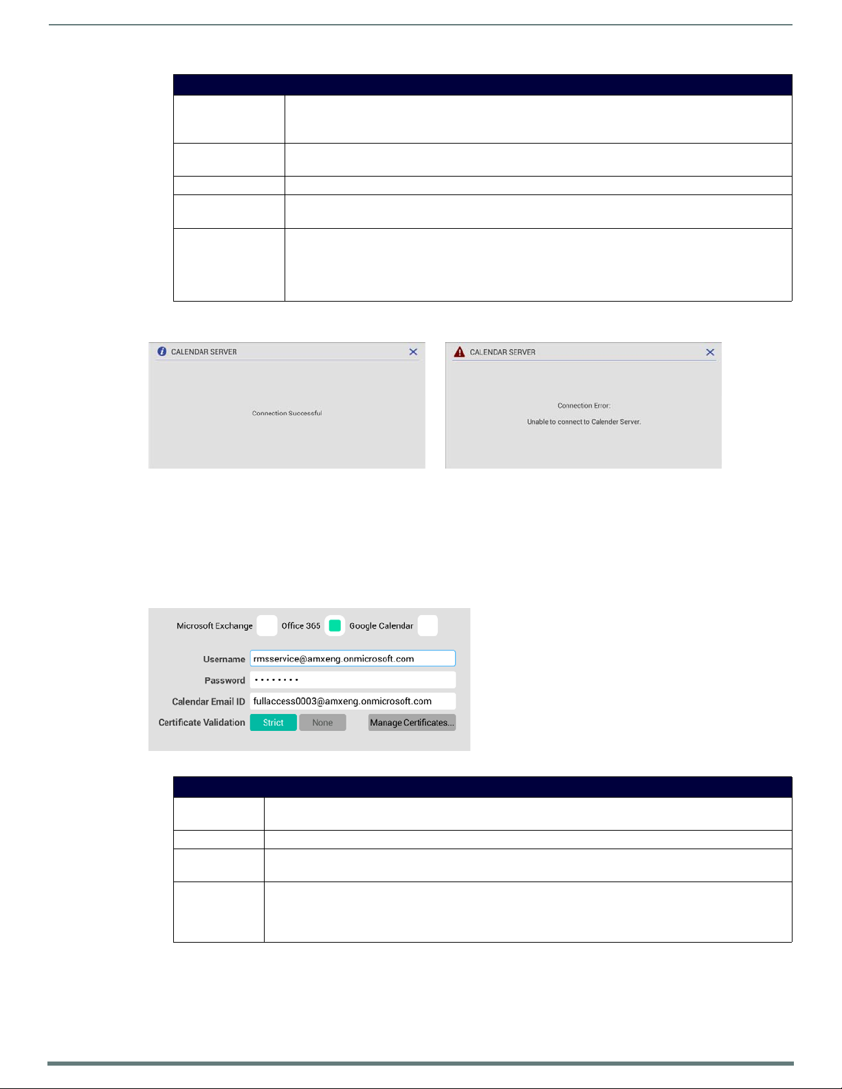
2. Fill in these f ields and press Verify to verify that the scheduling panel can connect to the scheduling system using the
information currently entered on this page. The panel will indicate if the connection attempt was successful (FIG. 27):
FIG. 27 CALENDAR SERVER (Verify) - Connection Successful/Connection Error
If the panel indicates that the connection attempt was unsuccessful, review all Calendar settings and retry.
3. Press Next to proceed (press Back to return to the NETWORK page).
NOTE: For more information, see Appendix A: Conf iguring RoomBook Panels for Microsoft Exchange & Off ice 365 on page 73.
Off ice 365
To conf igure the Acendo Book Panel for use with Off ice 365:
1. In the Setup Wizard: Step 3 - Calendar page, select Off ice 365 (FIG. 28) to invoke the following conf iguration settings:
FIG. 28 Office 365 Calendar Conf iguration Settings
Off ice 365 Calendar Configuration Settings
Username Enter the Username (including domain) required to login to the scheduling server (as required).
Example: "JaneDoe@acme.onmicrosoft.com".
Password Enter the Password required to login to the scheduling server (as required).
Calendar Email ID Enter the Email ID (including domain) used by the scheduling service.
Example: "ConfRoom1@acme.onmicrosoft.com"
Certificate
Validation
• Select Str ict to xxxxxx xxx xxx xxxxxxx.
• Select None to xxxxxx xxx xxx xxxxxxx.
• Select Manage Certif icates to open the Security (Advanced Settings) page (see FIG. 100 on page 56), which
provides access to Credential Storage options, as described in the Installing Certif icates section on page 59.
2. Fill in these f ields and press Verify to verify that the scheduling panel can connect to the scheduling system using the
information currently entered on this page.
3. Press Next to proceed (press Back to return to the NETWORK page).
NOTE: For more information, see Appendix A: Conf iguring RoomBook Panels for Microsoft Exchange & Off ice 365 on page 73.

Using the Scheduling Panel Setup Wizard
26
AMX RoomBook Scheduling Touch Panels - Instruction Manual
Google Calendar
To use Google calendar with Acendo Book, a Google Services account must be available. Refer to the Appendix C: Conf iguring
Google Resources on page 77 for details.
To conf igure the Acendo Book Panel for use with Google calendar:
1. In the Setup Wizard: Step 3 - Calendar page, Select Google Calendar (FIG. 29) to invoke the Add option:
FIG. 29
2. Press Add to invoke the Google sign-in page (FIG. 30):
FIG. 30 Google Sign-In Page
3. In the Google Sign-In Page, enter your Google Service account login information and press Next.
4. When prompted to allow Acendo Book to manage your calendars, review the terms described, and press Allow to proceed
Google Calendar Conf iguration Settings
(FIG. 31):
FIG. 31 Allow Acendo Book to manage Google calendars
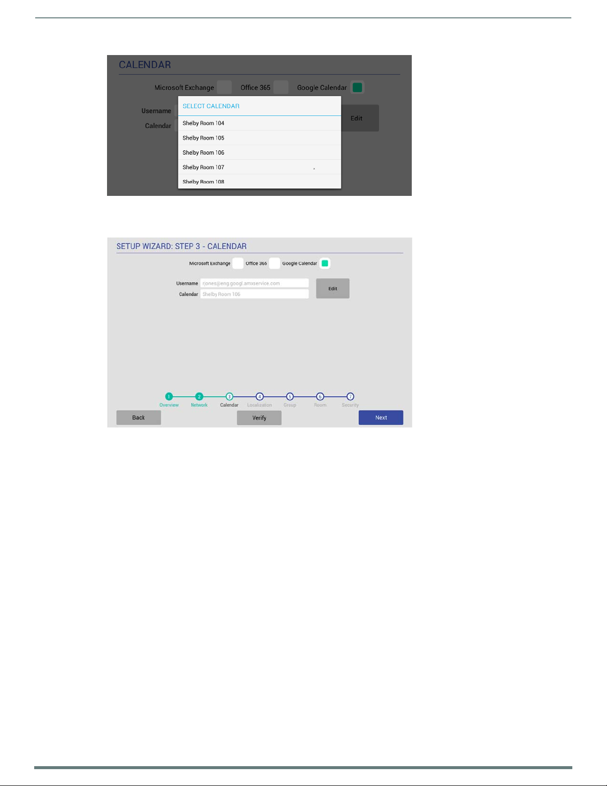
5. The SELECT CALENDAR window presents a listing of all Acendo Book panel-equipped rooms that are associated with Google
calendar. Press to select a Calendar/Room to use as the source of scheduling information for this panel (FIG. 32):
Using the Scheduling Panel Setup Wizard
27
AMX RoomBook Scheduling Touch Panels - Instruction Manual
FIG. 32
SELECT CALENDAR Window indicating a sample list of Calendars/Rooms
6. This selection closes the SELECT CALENDAR window, and displays an updated CALENDAR page, indicating the current Google
Username and the Calendar/Room associated with this panel (FIG. 33):
FIG. 33 CALENDAR Page i ndicating Go ogle Userna me and selected Calendar
7. Fill in these fields and press Verify to verify that the scheduling panel can connect to the scheduling system using the
information currently entered on this page.
8. Press Next to proceed (press Back to return to the NETWORK page).
NOTE: These settings can be changed later if necessary, via the CALENDAR Settings page (see Viewing/Editing Calendar Settings on
page 38).
 Loading...