

Page 1
Installation & Operating Manual
The Harman Advance Pellet Stove
“Ce manuel est disponible en Français sur demande”
R8
SAFETY NOTICE
PLEASE READ THIS ENTIRE MANUAL BEFORE YOU INSTALL AND USE YOUR NEW ROOM HEATER. FAILURE TO
FOLLOW INSTRUCTIONS MAY RESULT IN PROPERTY DAMAGE, BODILY INJURY, OR EVEN DEATH.
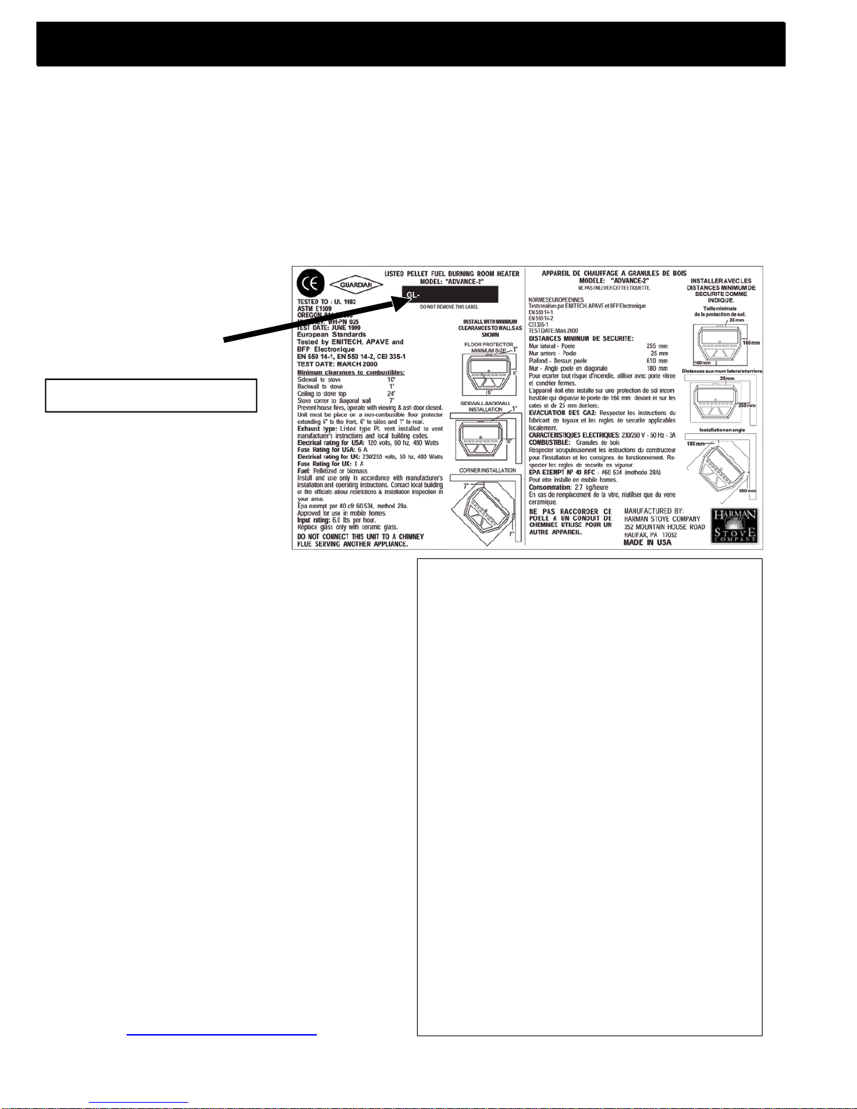
FOR USE IN THE U.S. AND CANADA. SUITABLE FOR INSTALLATION IN MOBILE HOMES
IF THIS HARMAN STOVE IS NOT PROPERLY INSTALLED, A HOUSEFIRE MAY RESULT. FOR YOUR SAFETY, FOLLOW
INSTALLATION DIRECTIONS.
CONTACT LOCAL BUILDING OR FIRE OFFICIALS ABOUT RESTRICTIONSAND INSTALLATION INSPECTION
REQUIREMENTS IN YOUR AREA.
CONTACT YOUR LOCAL AUTHORITY (SUCH AS MUNICIPAL BUILDING DEPARTMENT, FIRE DEPARTMENT, FIRE
PREVENTION BUREAU, ETC.) TO DETERMINE THE NEED FOR A PERMIT.
CETTE GUIDE D'UTILISATION EST DISPONIBLE EN FRANCAIS. CHEZ VOTRE CONCESSIONNAIRE DE HARMAN STOVE
COMPANY.
SAVE THESE INSTRUCTIONS.
Page 2
Introduction
The Advance Pellet Heater
This heating appliance does not just have automatic ignition, it has total automatic temperature control. The Advance
uses a small room sensor rather then a wall thermostat for a more accurate temperature control.
The Advance's control panel is designed for easy and efficient operation. It has 2 automatic modes of operation and 2
manual modes of operation. The Advance's specially designed burn pot and the "Advance Igniter" Automatic Ignition
System, allow the unit to burn a large variety of biomass fuels with varying ash content. The Advance feed system has a
maximum feed rate of 6 lbs. per hour and a minumum (maintenance) feed rate of 1.0 lbs. per hour.
This 0 to 48,000 BTU pellet stove has an accordian style heat exchanger system that allows maximum surface area for
the most efficient heat transfer in a smaller firebox.
The unit has an easy to clean combustion system with an ash pan that holds ash from 1 ton of burned premium pellets.
This unit is equipped with several different safety devices which will be explained later in this manual.
Please copy your serial
number from the label on your
stove to the box below.
SERIAL NUMBER
SAFETY NOTICE: IF THIS HARMAN ADVANCE PELLET
STOVE IS NOT PROPERLY INSTALLED. A HOUSE FIRE
MAY RESULT. FOR YOUR SAFETY, FOLLOW THE INSTALLATION DIRECTIONS. CONTACT LOCAL BUILDING OR
FIRE OFFICIALS ABOUT RESTRICTIONS AND INSTALLATION INSPECTION REQUIREMENTS IN YOUR AREA.
Harman Stove Company
352 Mountain House Road
Halifax, PA 17032
sales@harmanstoves.comsales@harmanstoves.com
Table of Contents
Automatic Operation 3
Manual Operation 5
ESP Control 7
Assembly & Installation 8
Venting 12
Maintenance 19
Trouble-Shooting 26
Specifications 27
Wiring Diagram 28
Feeder Parts 29
Parts List 30
Warranty 31
2
Page 3
Automatic Ignition/Operation
The Advance pellet stove is more than just automatic ignition, it is also automatic temperature
control. The automatic system will allow the fire size to be adjusted to match the heating
needs and even put the fire out if necessary. If heat is needed after the fire is out, the
Advance will automatically re-ignite and adjust the fire size to match the heating need. The
totally automatic room sensor mode is recommended because of its efficiency.
The unit can be switched between "AUTO" and "MANUAL" at any time during operation.
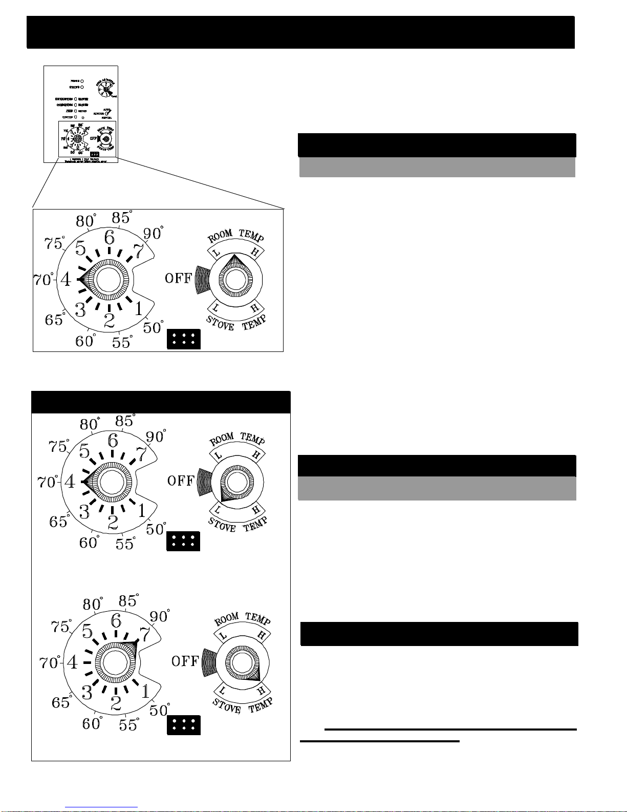
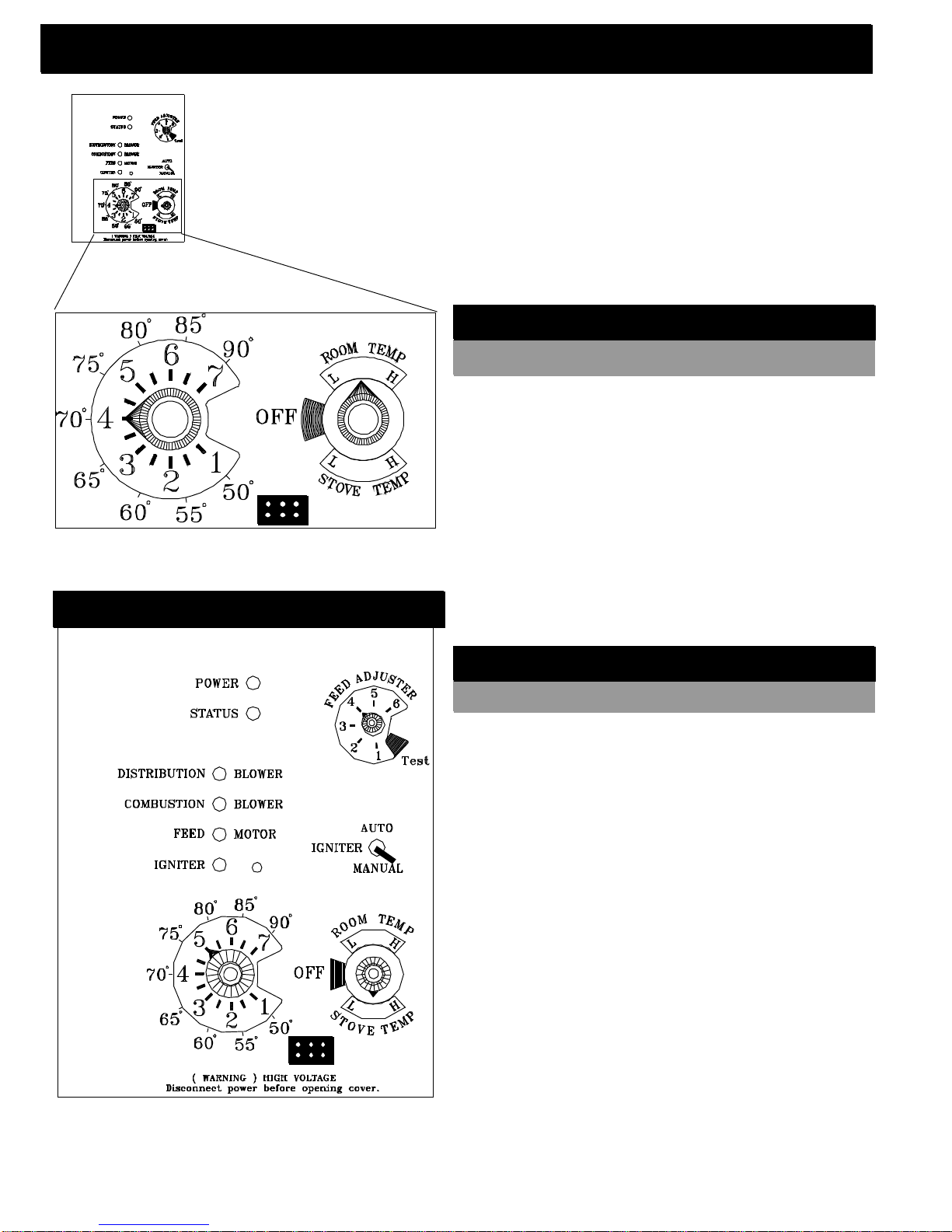
Room Temperature Mode: This setting will produce a room
temperature of 70 degrees with the distribution blower at
medium speed.
Stove Temperature Mode
Igniter switch to "AUTO"
Room Temperature Mode
In "Room Temp Mode" heat output is controlled automatically by the Room Sensing Probe. When the Room
Sensing Probe calls for heat, the stove will increase output. When the Room Sensing Probe is getting close to
the set temperature, the stove will begin to level off output and keep the fire burning at just the right temperature
to maintain that setting.
High output is determined by the feed rate setting. This setting, generally on #4, can be increased if
higher burn rates are necessary. The unit's maximum
burn rate should not create less than 1" of ash on the
burn pot front edge. See Fig.2, Page 4. Overfeeding is
not a safety concern, but fuel may be wasted if unburned
pellets fall into the ash pan.
In "Room Temp Mode" a constant fuel consumption
rate is sacrificed for exact room temperature. Therefore,
as it gets colder more pellets will be burned automatically.
The distribution blower speed will vary according to
the position of the mode selector pointer, and fire size.
This setting will produce medium heat with the
distribution blower on "low".
This setting will produce continuous maximum heat
output with the distribution blower at full speed.
Igniter switch to "AUTO"
Stove Temperature Mod
This allows for automatic ignition upon start-up only.
The unit can then be set at any desired setting. The heat
output and fuel consumption will remain constant regardless of room temperature. The unit's maximum feed rate
should not create less than 1" of ash on the burn pot front
adge. See Fig 2, Page 4.
The unit's low burn or maintenance setting is as
low as it will go. It will not go out unless it runs out of
fuel or is turned off.
Shut-Down Procedure
To kill the fire or stop burning the stove, turn the Mode Selector to
"OFF". This will cause the fire to diminish and burn out. When the fire burns
out and the stove cools down everything will stop.
If you pull the plug to shut down the stove, all motors will stop. This
may cause incomplete combustion and smoke in the firebox. If the load door
is opened the smoke may escape.
The best way to shut down the stove is simply let it run out of pellets,
then the stove will shut down automatically.
3
e
Page 4
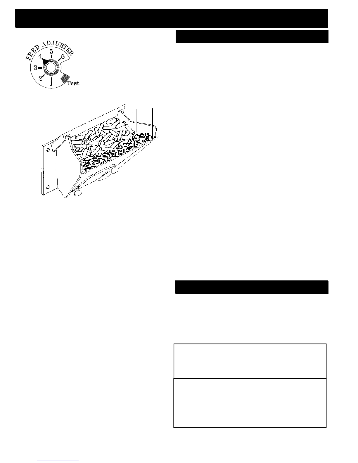
Fig. 1
Automatic Start Up
Igniter Switch to"AUTO"(up position)
60 HZ electrical source. The power light should be the
only light lit.
1. Turn Mode Selector to "OFF".
See Note 7.
1"
Fig. 2
2. Fill hopper with pellets.
3. Clean burn pot with scraper, if necessary.
4. If starting after an empty hopper, turn Feed
Adjuster to "TEST" (for one 60 second cycle).
will purge pellets into the auger tube and also allow
you to check the motors for operation. NOTE: The
auger motor will not operate with the view door or
ash pan door open.
5. Turn Feed Adjuster to #4.
Starting First Fire
Make sure the unit is plugged into a 120 VAC,
1
5
2
This
3
4
1. Fines are small pieces of broken pellets (sawdust). Fines do not
flow easily and often build up on the hopper funnel bottom angles.
These fines can be pushed into the feeder opening and then fill
the hopper with pellets. As the system works, they will be burned.
2. The "TEST" cycle will operate the feeder motor for exactly one
minute. Turning to "TEST" again and again may purge too much
fuel into the burn pot causing excessive smoke on start-up.
3. The firebox low pressure switch will not allow the auger motor or
the igniter element to operate if the view door or the ash pan door
are open.
4. Adjust Feed Rate. If this is your first fire or you are trying different
pellets, set the feed adjuster to #4, Fig. 1. This is a conservative
number and will probably need to be increased. After you know a
feed rate setting that works well, use that setting. Remember, if
your feed rate is too high you may waste fuel.
5. This is usually a weekly maintence procedure. Cleaning the
burn pot with the scraper with a small amount of new fuel in the
bottom is not a problem. First, scrape the ashes on the front of the
burn pot into the ash pan. Then scrape the holed surface downward
into the burn pot. When the stove is ignited these scrapings will be
pushed out by the feeder.
6. The ash pan can hold the ashes from approximately 1 ton of
premium fuel. This means the ashes will only need to be emptied
a few times a year.
7. Setting the feed adjuster # for maximum burn: With the unit
burning in "AUTO", turn to "Stove Mode" and put the fan on "H". Set
the Temperature Dial to #7. Allow the unit to burn for about 30
minutes and check ash on front of burn pot. Fig. 2. If the ash line is
larger than 1", turn the feed adjuster from #4 to #5. Allow another
30 minutes of burn time and check again. If , at #6 setting, a 1" or
less ash bed is not obtainable, it is not a problem. The 1" ash bed
is only a maximum burn rate and at most normal settings the ash
bed will be larger.
6. Flip the Igniter Switch up into the "AUTO" position.
7. Turn the Temperature Dial to desired room
temperature.
8. Turn Mode Selector to Room Temperature or Stove
Temperature.
9. Fill hopper with pellets and remove ashes as
required.
6
Battery Back Up
If a power outage is expected, switch the toggle switch
to Manual Mode. The Harman 502H Battery Back Up
is incapable of powering the igniter. If an automatic
ignition is attempted while the stove is being powered
by the battery back up, it may cause damage to both
the stove and the battery back up unit.
CAUTION
The stove is hot while in operation.
Keep children, clothing and furniture away.
Contact may cause skin burns.
Warning
"NEVER USE GASOLINE, GASOLINE-TYPE LANTERN
FUEL, KEROSENE, CHARCOAL LIGHTER FLUID, OR
SIMILAR LIQUIDS TO START OR "FRESHEN UP " A
FIRE IN THIS HEATER. KEEP ALL SUCH LIQUIDS
WELL AWAY FROM THE HEATER WHILE IN USE".
4
Page 5
Manual Ignition/Operation
The Advance Pellet Stove is capable of manual operation. This also allows the operator
to manually control operation during an emergency (i.e. igniter failure, when using a 502H
battery backup, or when using certain generators.)
The unit can be switched between "AUTO" and "MANUAL" at any time during operation.
Room Temperature Mode: This setting will produce a
room temperature of 70 degrees with the distribution blower
at medium speed.
Manual Stove Temperature Mode
NOTE: When starting the unit in the "AUTO"
mode and switching to "MANUAL", the fire must be
large enough to start the distribution blower. The
starting of the blower is a signal that the start cycle
is completed and the fire will not go out.
Igniter Switch to "MANUAL"
Room Temperature Mode
The fire will have to be lit with starting gel and a
match, or started automatically, see "Automatic Operation". Turn to "Manual" position when the fire is established.
The difference between "AUTO" Room Temperature Mode and "Manual" Room Temperature Mode is
that the fire will not go out as the room temperature goes
above the control board setting. The unit can only go to
low burn and will remain there until it runs out of fuel or
until more heat is needed and the feed rate increases.
Feed rate adjustments and dial settings are the same
as "AUTO" settings.
This setting will produce a large viewing fire without a
distribution blower operating.
Igniter Switch to "MANUAL"
Stove Temperature
The advantage of this mode is to allow the operator to have a large viewing fire without blowing extra heat
into the room.
During operation, with the temperature dial set at
#5 or less, the distribution fan will not operate. A #5 on
the temperature dial and a #5 on the feed adjuster is
approximately 80% output. It is not necessary to operate the distribution blower below this point. Therefore,
there can be a higher feed rate ( a larger viewing fire)
without an excess of hot air blowing into the room.
An example of when to use the Manual Stove Temperature Mode is if you want to watch a large fire and
the room is aleady up to temperature. The Stove Temperature Mode allows you to have a larger fire and a
lower sound level, without the distribution blower.
NOTE: During the use of this mode, if you keep
increasing the temperature dial setting to increase
the fire size, the distribution blower will automatically come on when the ESP Temperature reaches
350o F, or 81% output.
Mode
5
Page 6
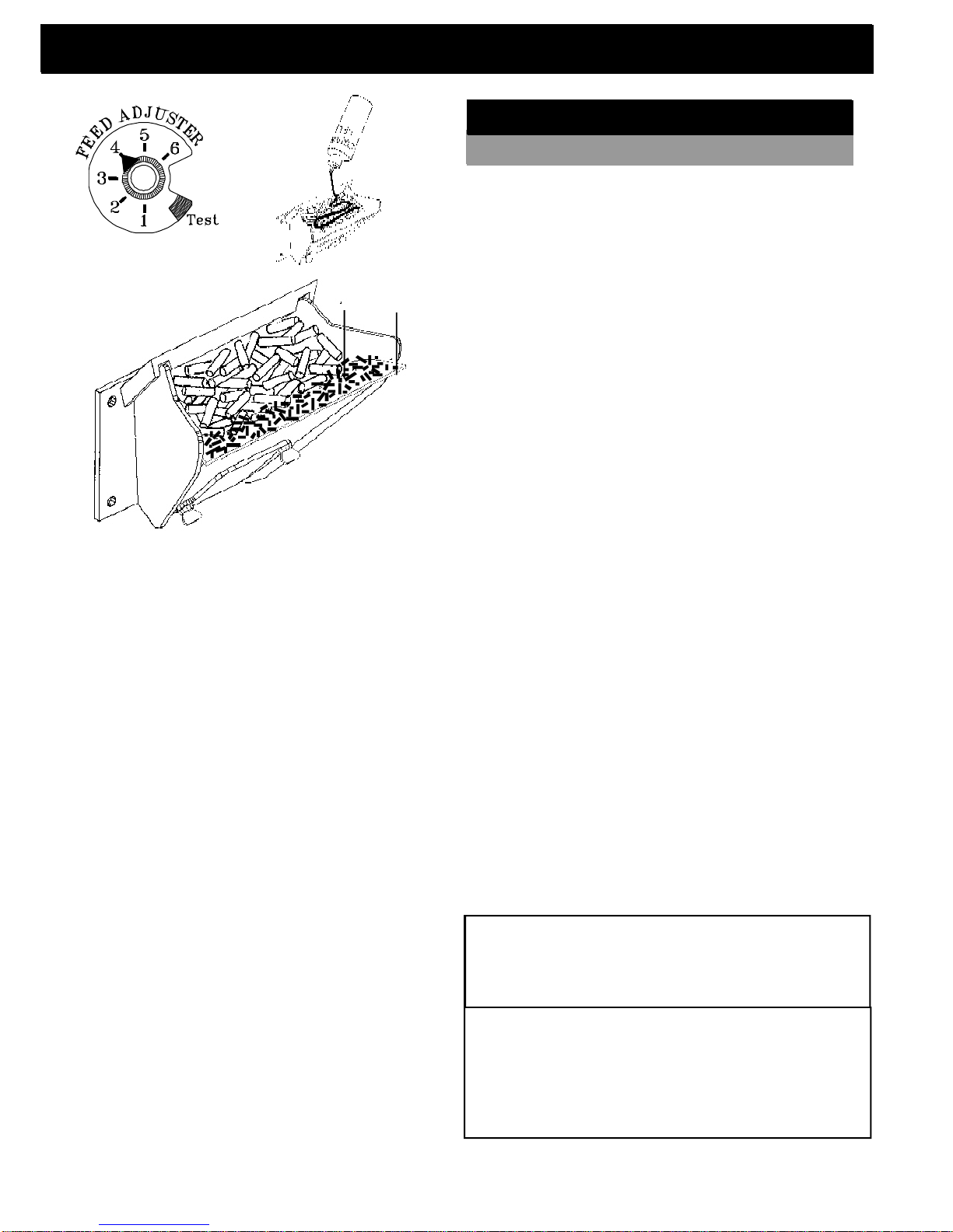
Fig. 3
Fig. 5
Manual Start Up
Fig. 4
Make sure the unit is plugged into a 120 VAC, 60 HZ
electrical source. The power light should be the only
light lit.
See Note
7.
1"
1. Turn FEED ADJUSTER to desired feed rate.
No. 4 is good for most pellets.
2. Turn the MODE SELECTOR to “OFF” and
then to the desired mode. This will reset con-
trol and start the combustion motor.
3. Turn the TEMPERATURE DIAL to the desired
setting.
4. Clean burn pot with scraper if necessary.
Starting First Fire
Igniter Switch to"MANUAL"
(down position)
4
5
1. Fines are small pieces of broken pellets (sawdust). Fines do not
flow easily and often build up on the hopper funnel bottom angles.
These fines can be pushed into the feeder opening and then fill
the hopper with pellets. As the system works, they will be burned.
2. The "TEST" cycle will operate the feeder motor for exactly one
minute. Turning to "TEST" again and again may purge too much
fuel into the burn pot causing excessive smoke on start-up.
3. The firebox low pressure switch will not allow the auger motor or
the igniter element to operate if the view door or the ash pan door
are open.
4. Adjust Feed Rate. If this is your first fire or you are trying different
pellets, set the feed adjuster to #4, Fig. 3. This is a conservative
number and will probably need to be increased. After you know a
feed rate setting that works well, use that setting. Remember, if
your feed rate is too high you may waste fuel.
5. This is usually a weekly maintence procedure. Cleaning the
burn pot with the scraper with a small amount of new fuel in the
bottom is not a problem. First, scrape the ashes on the front of the
burn pot into the ash pan. Then scrape the holed surface downward
into the burn pot. When the stove is ignited these scrapings will be
pushed out by the feeder.
6. The ash pan can hold the ashes from approximately 1 ton of
premium fuel. This means the ashes will only need to be emptied
a few times a year.
7. Setting the feed adjuster # for maximum burn: With the unit
burning in "AUTO", turn to "Stove Mode" and put the fan on "H". Set
the Temperature Dial to #7. Allow the unit to burn for about 30
minutes and check ash on front of burn pot. Fig. 5. If the ash line is
larger than 1", turn the feed adjuster from #4 to #5. Allow another
30 minutes of burn time and check again. If , at #6 setting, a 1" or
less ash bed is not obtainable, it is not a problem. The 1" ash bed
is only a maximum burn rate and at most normal settings the ash
bed will be larger.
5. Fill burn pot with pellets, only level with front
edge. (Do Not Over Fill).
6. Add starting gel on top of the pellets. Stir gel
into pellets for fast lighting.
7. Light starting gel with a match, and close the
door. Operation will begin when the fire reaches
the proper temperature.
3
8. Fill hopper with pellets and remove ashes as
required.
1, 6
CAUTION
The stove is hot while in operation.
Keep children, clothing and furniture away.
Contact may cause skin burns.
Warning
"NEVER USE GASOLINE, GASOLINE-TYPE LANTERN
FUEL, KEROSENE, CHARCOAL LIGHTER FLUID, OR
SIMILAR LIQUIDS TO START OR "FRESHEN UP " A
FIRE IN THIS HEATER. KEEP ALL SUCH LIQUIDS
WELL AWAY FROM THE HEATER WHILE IN USE".
6
Page 7
ESP Control
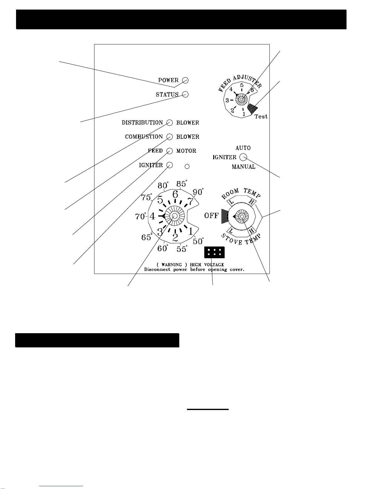
Power Light
Indicates power to the
control.
Status Light
Will be lit in either stove
or room temp mode when
pointer is not within off
position band except
after normal shut down.
Blinks to indicate errors
listed below.
Indicates power to
distribution blower.
Indicates power to
combustion blower
Indicates power to the
feed motor.
Indicates power to the
igniter.
Feed adjuster
Sets the maximum
feed rate
Test
Runs all motors at full
speed for one minute
to check operation.
After two minutes the
stove will go to
minimum burn and
the blowers will
alternate from high to
low every minute to
remind you that you
are still in "Test
Mode".
Igniter switch
Set to appropriate
Start-Up mode.
Distribution Blower
speed adjustment range.
L = low
H = high
Variable speed anywhere
between L and H;
although as the stove
temp. goes up , so does
the low end of the scale.
Temp dial
Allows you to adjust the room temperature in Room
Temp Mode using the outer scale marked in degrees
Fahrenheit. It also allows you to adjust the stove
temperature while in Stove Temp Mode using the
inner scale marked from 1 to 7.
Status light error messages:
1 Blink: Indicates control board self diagnostic failure.
This requires a manual reset*.
3 Blinks: Indicates ESP (Exhaust Sensing Probe) failure. This requires a manual reset*.
4 Blinks: Can occur only in Room Temp Mode and indicates Room Sensing Probe failed or not installed. If a
Room Sensing Probe is then installed, the status light
will automatically reset.
NOTE: Unit will not start in "AUTO" with this status error.
5 Blinks (In Igniter Auto. Mode Only): Indicates that the
unit has failed to light after 4 consecutive igniter cycles, 32
minutes total. To reset - Turn Mode Selector to "OFF", then
turn to either mode again.)
Dealer Diagnostic Port
For dealer maintenance only.
Requires special DDM monitor
supplied to Harman Dealers
exclusively.
Mode Selector
Allows you to choose between
Room Temp Mode, Stove Temp
Mode, or OFF. Also allows you
to vary the distribution blower
speed by turning the knob to
the high or low side of each
mode.
6 Blinks : Indicates that the control has calculated poor or
incomplete combustion occurring for more than 50 minutes. See Troubleshooting section for more details.
A six blink status may be set if the stove is allowed to run
out of pellets. To reset, turn mode selector to "OFF" then
back on to the desired mode. If the unit was not out of pellets, see Troubleshooting section for more details.
* Manual reset- disconnect power cord for a few seconds
and reconnect. If error still occurs call your Dealer.
NOTICE: When power is given to the stove, the control board
will blink a few times to indicate current version of control board.
This should not be confused with error messages.
7
Page 8
Installation
When installing and operating your Harman Advance
Pellet Stove, respect basic safety standards. Read these
instructions carefully before you attempt to install or operate the Advance. Failure to do so may result in damage to
property or personal injury and may void the product warranty.
Consult with your local building code agency and insurance representative before you begin your installation
to ensure compliance with local codes, including the need
for permits and follow-up inspections.
Several issues must be addressed when selecting
a suitable location for your Advance Pellet Stove. Observing required clearances to combustible materials, the proximity to a safe chimney or venting system, and the accessibility of electrical supply must all be considered. In addition, selecting a location that takes advantage of the
building's natural air flow is also desirable to maximize
the heating effectiveness of the heater. In many cases,
this is a central location within the building.
Adequate combustion and ventilation air must be provided.
Place the stove on a noncombustible floor or UL approved floor protector that extends 6 inches to the front, 6
inches to the sides and 1 inch to the rear of the stove. Fig.
8.
Place the stove away from combustible walls at least
as far as shown in figures 6, and 7.
Note that the clearances shown are minimum for
safety but do not leave much room for access when cleaning or servicing. Please take this into account when placing the stove.
7"
FLOOR PROTEC TOR
7"
Fig.6
1"
10"
FLOOR PROTECTOR
Fig.7
Mobile Home Installation
When installing this stove in a mobile home several
requirements must be followed:
1. The unit must be bolted to the floor. This can be
done with 1/4" lag screws throught the 2 holes in
the base plate shown in Fig. 13, Page 9.
2. The unit must also be connected for the outside
air. See page 12.
3. Floor protection and clearances must be followed
as shown above.
4. Unit must be grounded to the metal frame of the
mobile home.
CAUTION: This appliance must be vented to the
outside.
Due to high temperatures, the stove should be placed
out of traffic and away from furniture and draperies.
Children and adults should be alerted to the hazards
of high surface temperatures and should stay away to
avoid burn to skin and/or clothing.
Young children should be carefully supervised when
they are in the same room as the stove.
Clothing and other flammable materials should not
be placed on or near the stove.
1"
6" 6"
FLOOR
PROTECTOR
Installation and repair of this stove should be done by
a qualified service person. The appliance should be inspected before use and at least annually by a qualified
service person. More frequent cleaning will be required. It
is imperative that control compartments, burners, and circulating air passageways of the stove be kept clean.
AFTER THE INSTALLATION IS COMPLETED
Before the first fire is lit, check and record
the high and low draft reading numbers on page
10. Make adjustments to the low draft at this time,
if necessary. See page 10.
8
6"
Fig.8
Page 9
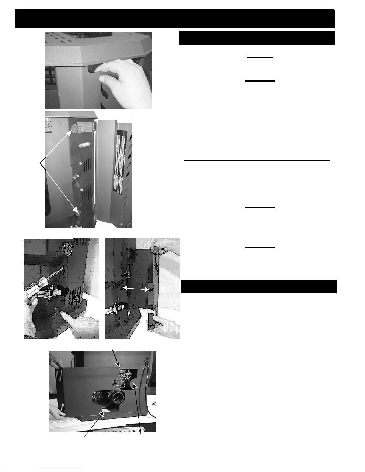
Removing Side Doors for Installation
Removing Side Doors
Use hand hole to swing open side doors to at least
90o.
Side
Door
Fig. 9
Remove side doors by lifting upward on the door until
the bottom pin is out of its hole. Move the bottom of
the door out and away from the pedestal base about
1/2". Allow the door to slide downward until the top
door pin is out of its top hole.
NOTE: Always remove the side doors and rear
shields to move the unit. This will keep them from
getting damaged.
Figure 9
Figure 10
Side Door
Magnets
Rear
Shield
Fig.11
Side Door
Fig.10
Rear
Shield
Fig.12
Rear Shield Retaining clip
Removing the Rear Motor Shield Sheet Metal.
NOTE: Disconnect power to the unit before
removing the motor shields. Danger of electrical
shock. Hot and moving parts could cause injury.
Figure 11
There are (2) #10 hex head screws holding each rear
shield. Using a 5/16" nut driver or socket, loosen the
(2) screws about 4 or 5 turns.
Figure 12
Slide the rear shields straight outward until the ends
come out of the rear retaining clips, as seen in Fig.13.
Placing Rear Shields Back on Unit
1. When replacing the shields, always insert the top
and bottom ends of the sheet metal into the retaining
clips first.
2. Slide the shields straight inward until the (2) hex
head screws are fully inserted into the stove slots.
3. Make sure the top edges of the shield are against
the hopper bottom and tighten screws.
Rear
Shield
Fig.13
Skid Hold Down
Screws
Outside Air
Flex Hole
Knockout
Rear Shields are split around the Flue Tail pipe and
outside Air Hole Knockout. This will allow removal and
installation of the rear shields with the unit completely
installed.
9
Page 10
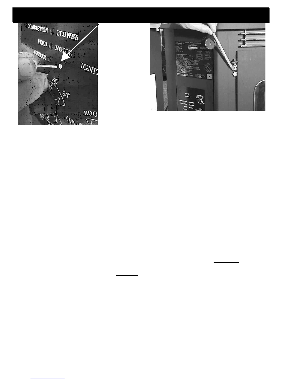
Fig.14
Low Draft Voltage Adjustment
Combustion
Motor Speed
Control
Low draft only
set point.
The small straight
screwdriver slot is
plastic; therefore,
the unit can be
adjusted while in
operation.
Fig.15
:
Draft Meter bolt hole location
These units are pre-tested at the factory with
exactly 120 Volts A.C., 60 Hz. They are checked and
adjusted for firebox tightness, gasket leakage, motor
operation and igniter operation. The Advance is then
factory set at a mid-point adjustment and in most cases
will not need any adjustments. NOTE: The factory low
draft setting may not be correct for the unit's
permanent installation conditions.
The control board on the Advance is equipped
with a low draft adjustment port. Located on the control
face just to the right of the igniter light. See Figure 14.
This voltage adjustment is provided to allow the unit to
be adjusted for the household voltage where the unit is
going to be in permanent operation. NOTE: The line
voltage varies from area to area and often home to
home.
The low draft voltage should be adjusted to
achieve the most efficient burn on low burn or
"maintenance". This voltage adjustment allows the
installer to change the low voltage set point approximately
15 volts. This adjustment should be done by the installer
during set up because a draft meter reading is required
to insure proper set up.
If the unit is not adjusted properly, it does not
cause a safety concern. If the unit is adjusted too high,
only effiency is lost. If the unit is adjusted too low, the low
draft pressure switch will not allow the feeder motor or
the igniter to operate.
Fig.1
A simple draft test should be performed after
completing the flue pipe installation. To record the
results for future reference:
1. Plug unit into a 120VAC, 60 HZ outlet.
2. Close the hopper lid, front view door, and the ash
pan. Neither pellets or a fire are required for this test.
3. With the mode selector in the "OFF" position, turn
the feed adjuster to "TEST".
4. Record the high draft_____in W.C. (Normal is -.50
to -.60) The control will be on the High Draft for a total
of 2 minutes.
5. After 2 minutes is up, the combustion motor will go
down to low draft and the distribution blower will go on
high. Allow approximately 15 seconds to pass for the
combustion motor to slow before checking the low
draft.
6. If the low draft is between .35 and .45, record the
reading _____ in W.C. If the reading is higher, slowly
turn the set screw counter-clockwise until the draft
lowers. If the reading is lower, very slowly turn the set
screw clockwise until the draft increases.
NOTE: The test mode alternates from high to low
draft every 60 seconds. If more time is needed
for draft adjustment, wait until the next low draft
cycle.
NOTE: In some cases, the draft may not go as low
as .35 even with the set screw completely counterclockwise.
MODIFICATIONS
High Altitude (7,000 - 10,000 ft.)A combustion
fan blade change can be made by an authorized
Harman Dealer. These changes must be done with
the use of a draft meter. These changes affect the low
and high burn rate air to fuel ratios.
10
Page 11

Room Sensor and Air Grill Installation
Room Sensor Installation
Fig. 16
The room sensor is a small temperature sensor
on the end of a 60" gray wire. This sensor is installed
much like a standard wall thermostat. Because it is so
small, it can be hidden along the trim of a doorway or
even up the leg of a coffee table. There is a remote
room sensor port on the rear of the unit for easy external connection. Use standard 18-2 thermostat wire to
extend the distance to the desired location (100' maximum). The room sensor should be installed in the location where you want to control the temperature.
NOTE: Distances of more than 25 feet from the
unit or in another room are not recommended. It is
recommended that the room sensor be installed, even
if only installed on the rear of the unit as a return air
sensor. The room sensor is essential for the Advance's
excellent efficiency.
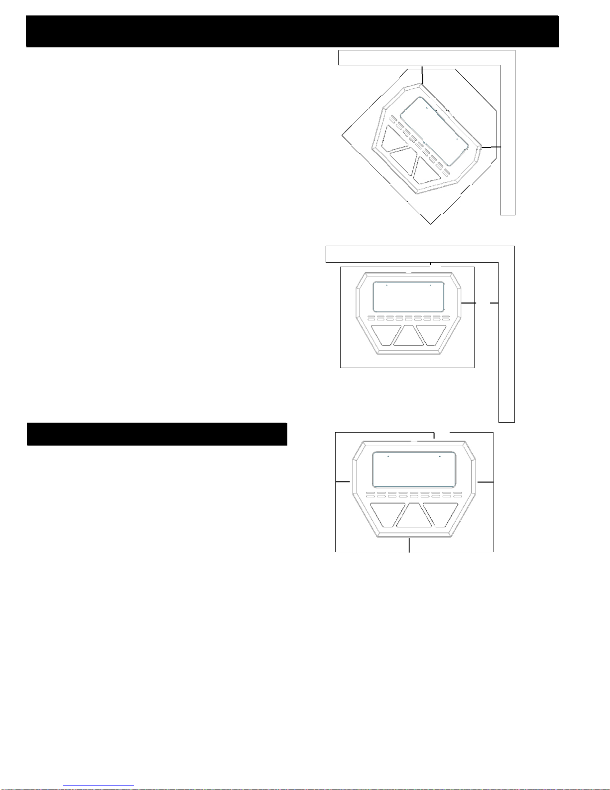
Gold Air Grill Installation
Fig. 17
Insert the two tail end hooks of the Air Grill Assembly
up under the stove top edge. Insert inward until the
two center hooks drop into the stove body slots in the
front of the unit.
REMINDERS
Hopper Lid
Foam Gaskets
Fig. 18
Do not allow pellets or sawdust to build up on the
hopper lid gasket.
Inspect the hopper lid gasket for damage. A good
hopper lid seal is very important for proper
operation.
11
Page 12

Fig.19
+ = Positive static pressure
= Negative static pressure
Venting
A combustion blower is used to extract the combustion gases from the firebox. This causes a negative pressure in the firebox and a positive pressure
in the venting system as shown in fig. 19. The longer
the vent pipe and more elbows used in the system,
the greater the flow resistance. Because of these
facts we recommend using as few elbows as possible and 15 feet or less of vent pipe. The maximum
horizontal run should not exceed 48". If more than
15 feet of pipe is needed, the diameter should be
increased from 3" to 4" because a larger pipe causes
less flow resistance. Be sure to use approved
pellet vent pipe wall and ceiling pass- through
fittings to go through combustible walls and
ceilings. Be sure to use a starting collar to attach
the venting system to the stove. The starting collar must be sealed to the stove with high temp
silicone caulking.
Vent Pipe
Pellet venting pipe ( also known as PL vent ) is
constructed of two layers with air space between
the layers. This air space acts as an insulator and
reduces the outside surface temperature to allow a
clearance to combustibles of only 3 inches. The
sections of pipe lock together to form an air tight
seal in most cases; however, in some cases a perfect seal is not achieved. For this reason and the
fact that the Advance operates with a positive vent
pressure, we specify that the joints also be
sealed with clear silicone.
Outside Air
Inlet Cover part#
1-10-08542
Room Sensor
Connection Ports
Outside air flex pipe
goes here
Flex pipe part#
2-00-08543
Outside air is optional except in mobile homes
and where building codes require. The benefit of
outside air is mainly noticed in small, very tight
houses.
To install outside air use 2 3/8" I.D. flex pipe
part number 2-00-08543. There is a break-away hole
on the rear panel which must be removed before
connecting the flex pipe. The pipe should be run outside and terminate to the side or below the vent pipe
outlet so the flue outlet is more than 12" from the
inlet cover. The maximum length run of this pipe is
15 feet. If a longer run is needed, the size must be
increased to 3". Inlet cover part number 1-10-08542
should be used to keep birds, rodents, etc. out of
pipe.
HRV
When installing in a house with a Heat Reclaiming Ventilation System (HRV) be sure the system is
balanced and is not creating a negative pressure in
the house.
12
Page 13

Venting
mal operation and allows the stove to be installed closest to the wall. One inch from the wall is safe; however, two or three inches allows better access to remove the rear panel. The vertical portion of the vent
should be three to five feet high. This vertical section
will provide natural draft in the event of a power failure.
#1 Preferred method
This method provides excellent venting for nor-
Fig.20
3 ft.
to
combustibles
#2 Preferred method
This method also provides excellent venting for
normal operation but requires the stove to be installed
farther from the wall. The vertical portion of the vent
should be three to five feet high and at least three inches
from a combustible wall. This vertical section will provide natural draft in the event of a power failure.
Fig.21
3 ft.
to
combustibles
CAUTION
KEEP COMBUSTIBLES (SUCH AS
GRASS, LEAVES, ETC.) AT LEAST 3
FEET AWAY FROM THE FLUE OUTLET
ON THE OUTSIDE OF THE BUILDING.
13
Page 14

Venting
This method also provides natural draft in the event
of a power failure. If the chimney condition is questionable you may want to install a liner as in method
#6.
#3 Installing into an existing
chimney ( US only )
This method can be used for normal operation.
Fig.22
#4 Installing into an existing
fireplace chimney ( US only )
This method can be used for normal operation.
This method also provides natural draft in the event
of a power failure.
The damper area must be sealed with a steel
plate or fiberglass. A cap should be installed on the
chimney to keep out rain. If the chimney condition is
questionable you may want to install a liner all the
way to the top as in Method #5.
Fig.23
14
Page 15

Venting
#5 Installing into an existing fireplace
mal operation. This method also provides natural draft
in the event of a power failure.
quired that the vent pipe extend all the way to the top
of the chimney.
the chimney to keep out rain. Be sure to use approved
pellet vent pipe fittings. Seal pipe joints with silicone in
addition to the sealing system used by the manufacturer. Pipe size should be increased to 4" using this
method.
chimney ( US and Canada)
This method provides excellent venting for nor-
In Canada and some places in the US it is re-
In this method a cap should also be installed on
Fig.24
#6 Installing into an existing
chimney ( US and Canada )
This method provides excellent venting for normal operation. This method also provides natural
draft in the event of a power failure.
In Canada and some places in the US it is required that the vent pipe extend all the way to the top
of the chimney. The pipe or liner inside the chimney
should be 4"diameter.
In this method a cap should also be installed
on the chimney to keep out rain.
Fig.25
15
Page 16

Venting
12" min.
3" min.
3" min.
PL vent manufacturer's
firestop spacer and
support.
Storm collar
Flashing
3" min.
No insulation or other
combustible materials
are allowed within 3" of
the PL vent pipe.
Fig. 26
18"
Fig. 27
#7 Installing through the ceiling vent
Through the ceiling vent, follow PL vent
manufacturer's recommendations when using wall
and ceiling pass through.
Minimum flue vent configuration
It is recommended that outside air be installed with
this venting configuration.
Fig. 28
16
Page 17

Venting
Requirements for Terminating the
Venting
WARNING: Venting terminals must not be re-
cessed into a wall or siding.
NOTE: Only PL vent pipe wall pass-throughs and
fire stops should be used when venting through combustible materials.
NOTE: Always take into consideration the effect
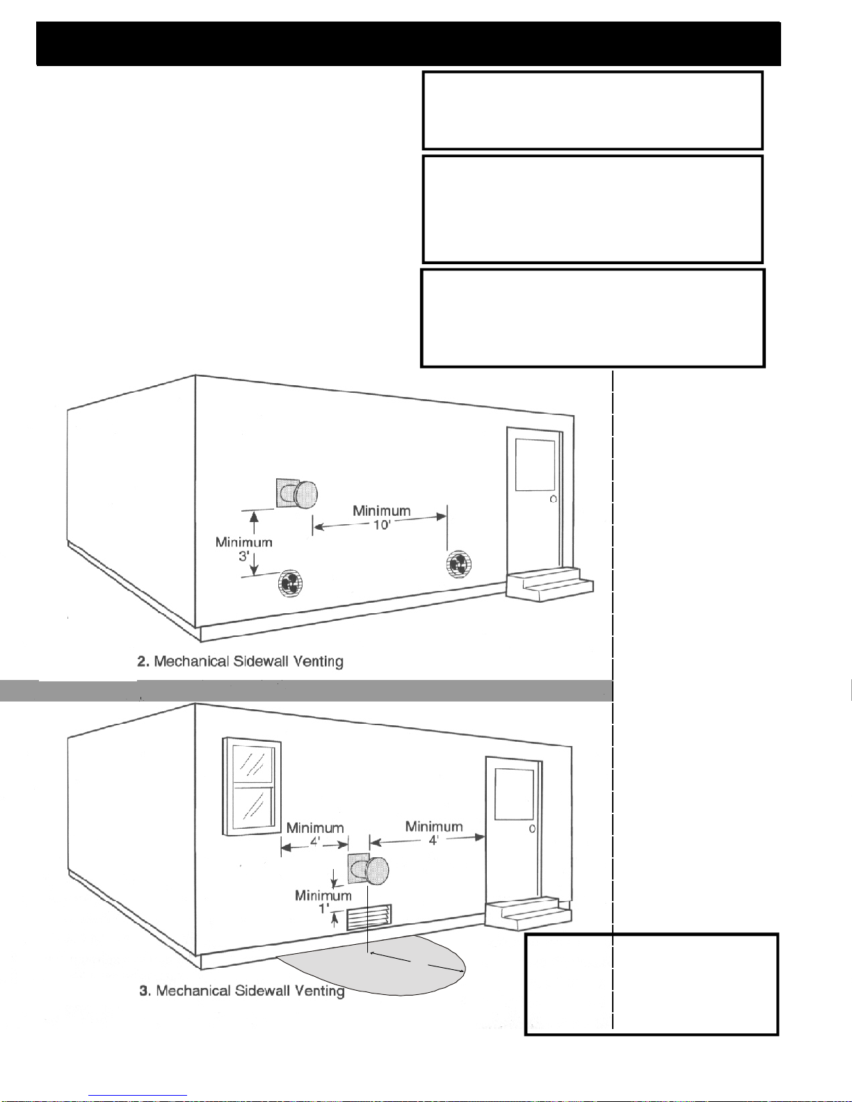
the prevailing wind direction or other wind currents will
cause with flyash and /or smoke when placing the termination.
In addition, the following must be observed:
A. The clearance above grade must be a minimum of 18".
B. The clearance to a window or door that may
be opened must be a minimum of 48" to the side, 48"
below the window/door, and 12" above the window/
1
door.
( with outside air installed, 18” )
C. A 12" clearance to a permanently closed window is recommended to prevent condensation on
the window.
D. The vertical clearance to a ventilated soffit located above the terminal within a horizontal distance
of 2 feet (60 cm) from the center-line of the terminal
must be a minimum of 18".
E. The clearance to an unventilated soffit must
be a minimum of 12".
F. The clearance to an outside corner is 11" from
center of pipe.
G. The clearance to an inside corner is 12".
H. A vent must not be installed within 3 feet (90
cm) above a gas meter/regulator assembly when measured from the horizontal center-line of the regulator.
1
I. The clearance to service regulator vent outlet
must be a minimum of 6 feet.
1
J. The clearance to a non-mechanical air sup-
ply inlet to the building or the combustion air inlet to
any other appliance must be a minimum of 48”.
K. The clearance to a mechanical air supply
inlet must be a minimum of 10 feet.
1
(with outside air installed, 6 feet )
L. The clearance above a paved sidewalk or a
paved driveway located on public property must be
a minimum of 7 feet.
M. The clearance under a veranda, porch, deck
1,2
or balcony must be a minimum of 12 inches.
NOTE: The clearance to vegetation and other
exterior combustibles such as mulch is 36” as measured from the center of the outlet or cap. This 36”
radius continues to grade or a minimum of 7 feet
below the outlet.
1
Certain Canadian and or Local codes or regu-
lations may require different clearances.
2
A vent shall not terminate directly above a sidewalk or paved driveway which is located between
two single family dwellings and serves both dwellings.
3
Only permitted if veranda, porch, deck, or balcony is fully open on a minimum of 2 sides beneath
the floor.
NOTE: Where passage through a wall, or
partition of combustible construction is desired,
the installation shall conform to CAN/CSA-B365.
(if in Canada)
1
Insid e
Corn er
Detail
1
1,3
Fixed
Closed
Openable
= Vent terminal = Air supply inlet
V
A
Openable
17
Fixed
Closed
= Area where terminal is not permitted
Page 18
Venting
DO NOT INSTALL A FLUE DAMPER IN THE
EXHAUST VENTING SYSTEM OF THIS UNIT.
DO NOT CONNECT THIS UNIT TO A
CHIMNEY FLUE SERVING ANOTHER
APPLIANCE.
INSTALL VENT AT CLEARANCES
SPECIFIED BY THE MANUFACTURER
Mobile home installation should be done in
accordance with the Manufactured Home
and Safety Standard (HUD), CFR 3280,
Part 24.
WARNING
DO NOT INSTALL IN SLEEPING ROOM
CAUTION
THE STRUCTURAL INTEGRITY OF THE
MOBILE HOME FLOOR, WALL, AND
CEILING/ROOF MUST BE MAINTAINED.
CAUTION
KEEP COMBUSTIBLES AWAY
FROM FLUE OUTLET.
18
3'
Keep combustible materials such as
grass, leaves, etc. at least 3 feet away
from the point directly under the vent
termination.
WARNING
Page 19

Maintenance - Emptying Ashes
Ash Pan Removal and Reattachment
Fig. 29
Fig. 30
Release spring latches on the right and left side of the ash
Slide ash pan forward enough to lift with center handle.
Empty ashes and reinstall ash pan.
Ashes should be placed in a metal container with a
tight fitting lid. The closed container of ashes should
be placed on a noncombustible floor or on the ground,
well away from all combustible materials, pending final
disposal. If ashes are disposed of by burial in soil or
otherwise locally dispersed, they should be retained in
the closed container until all cinders have thoroughly
cooled.
Inspect the gasket rope for damage. Replace if necessary.
Figure 29
Open side doors.
Figure 30
pan.
Figure 31
Figure 32
Fig. 31
Fig. 32
Fig. 33
Figure 33
Insert spring latch front hooks into the ash pan side slots.
Push both latches to the rear at the same time to latch.
Soot and Fly Ash
The products of combustion will contain small particles
of fly ash. The fly ash will collect in the exhaust venting system and restrict the flow of the flue gases. Incomplete combustion, such as occurs during startup, shutdown, or incorrect operation of the room heater, will lead to some soot formation which will collect in the exhaust venting system. The
exhaust venting system should be inspected at least once
each year to determine if cleaning is necessary.
When removing the ash pan to empty ashes, you will
note a build up of ash fines behind the ash pan. This space
behind the ash pan was designed to allow the fines to fall out
of the vertical heat exchangers and collect where they are
easily cleaned out, rather than going into the flue pipe where
it would be difficult to clean. These fines should not be allowed to build up. They may not allow the ash pan to be
seated into its gasket properly. NOTE: If an extreme amount
of force is required to snap the latch on one or both
sides of the ash pan, the area behind the ash pan should
be checked for ash fine build up.
19
Page 20

Maintenance - Cleaning Glass on View Door
Fig. 34
WARNING
Door latch may
be hot!
Receiving Bolt
Opening and Closing the View Door
Opening:
The view door must be opened for cleaning of
the glass and scraping of the burn pot. This should be
done with the unit off and cool, in most cases. Although
the glass can be cleaned and burn pot scraped while
the unit is at low burn.
1. Using scraper as shown in Fig. 34and 35, lift the
door latch forward and up.
2. Swing the door open to the left, stopping the swing
when resistance is felt. Forcing the door open further
then was designed may cause damage to the door or
it's hinges.
CAUTION
Do not put excessive downward pressure on the
latch end of the door while in the open position.
If the door is going to be opened for an extended period
of time, it is suggested that it be removed (see Fig. 36)
and set safely aside.
3. Inspect the door gasket and glass gaskets for worn
or missing pieces. Replace if necessary. (Fig. 37)
Fig. 35
Fig. 36
Closing:
When closing the door, always hold the door
latch all the way up until it has caught the receiving
bolt. Then push the latch downward and back until the
door is fully seated. See Fig. 35.
Removing View Door:
To remove the view door from the stove, hold
the door by the bottom and lift upward off of the hinge
pins.See Fig. 36.
Inspect the door gasket.See Fig. 37.
REPLACE GLASS WITH
CERAMIC GLASS ONLY.
Fig. 37
20
Page 21

Fig. 38
Fig. 39
Maintenance - Burn Pot
Burn Pot Cleaning and
Maintenance
1. Scrape the top holed surface and sides of the
burn pot.(Fig 38) It is not necessary to completely
remove all material from the burn pot. The excess
will be pushed out during the next use.
2. Loosen the (2) wing thumb screws on the lower
front angle of the burn pot. (Fig. 38)
3. Lift off the clean-out cover (Fig.39) to open the
bottom clean-out chamber. (Fig.40)
Disconnect the power to the unit before
removing cover.
4. Clean ash buildup from inside the chamber while
cover is off. Use the scraper to tap on the top front
edge of the burn pot. This will help knock pieces of
ash, loosened by the scraping process, down
through the holes. It also helps knock scale off of
the igniter element.
Figure 40
The igniter is made to be removable for
service by insulated male/female wire connectors.
These connections between the hot leads (the
wires inside the burn pot) and the cold leads (the
wires from the control board) are always pulled to
the rear of the feeder body. (Not coiled inside the
burn pot.)
It is very important that these connections
are to the inside rear of the feeder body. Also, the
extra wire of the igniter wire service loop must be
pulled out through the rear of the feeder and tied
up so that it will not be damaged by any moving
Burn pot igniter
parts. See page 25.
Disconnect the power to the unit before
removing cover.
DANGER
DANGER
Fig. 40
Viewed from below through the ash pan
opening.
Warning
Use caution when cleaning burn pot clean-
out chamber. Do not damage the high
temperature igniter wires.
Igniter hot lead wires
(high temperature)
Note: The hot lead/cold lead connection
must always be pulled to the rear of the
feeder body before operation.
21
Page 22

Maintenance - Flame Guide and Brick Panel
Firebox Brick Panel
Fig. 41
Fig. 42
Flame Guide/
Brick panel
holder
Burn pot
Flame Guide and Brick Panel
Removal for Cleaning
Figure 42
Slide brick panel straight upward with both hands.
Figure 43
While holding the brick panel up with one hand,
remove the flame guide from the top of the burn
pot.
Fig. 43
Fig. 44
Fig. 45
Figure 44
Slide the brick panel into the left corner of the
firebox with the panel resting on the top edges of
the burn pot. Rotate the right side of the brick panel
through the door opening.
Reverse this operation to reinstall the brick panel
after cleaning.
22
Page 23

Maintenance - Combustion Intake Cover
Cover Retainer Handle
Fig. 46
Cleaning and Maintenance for the
Combustion Intake Cover
You will need to remove the combustion
intake cover to clean the fan blades and rear flue
tube.
Figure 46
Rotate the retainer cover handle counter-clockwise
upward as far as it will go (approximately 90o).
These surfaces must be even to
close retainer handle.
Fig. 47
Intake Cover Handle
ESP Probe
(in rear of flue
tube)
Right Side Tab
Combustion
Intake Cover
Right Side Retaining Slot
Figure 47
Hold the intake cover handle and pull until the side
of the cover at the retainer handle end comes away
from the stove body, approximately 15-20o, slide
the right side tab out of the retaining slot.
Figure 48
Clean and inspect the fully exposed combustion
fan blade and flue tube.
Reinstall the combustion intake cover by
first sliding the right side tab into the retainer slot
seen in Figure 47.
Rotate the cover inward until the cover fits
into its hole.
Make sure the two faces (Fig.46) of the
cover and retainer spacer are even and rotate the
retainer handle clockwise until it stops.
Fig.48
Combustion Fan Blade
CAUTION
Excessive cleaning force could bend the
small stainless steel ESP Probe, causing
damage.
23
Page 24

Fig. 49
Fig. 50
Fig. 51
Maintenance - Heat Exchanger
Cleaning the Heat Exchanger
System
Slot
1. Remove brick panel and flame guide. See Pg 22.
2. Remove the ash pan. See Page 19.
Tab
Hook Tab
Center Lock
3. Remove flue baffles located on each side of
the burnpot, see Fig. 49 & 50. The baffle is held in
place by inserting the tab into the slot (located
toward the outside of the firebox) and resting it on
the hook tab located beside the burnpot.
4. Pull the pointed end of the baffle slightly front
with one hand while pushing up from below with
the other hand. See Fig. 50.
5. With the baffle released from the tabs, rotate
the pointed end toward the door opening. Lift
baffle up and out.
The right and left baffle are interchangeable.
6. Now remove the heat exchanger baffle plates.
See Fig. 51 & 52. To remove the left plate, slide
the center lock to the right. To remove the right
plate, slide the center lock to the left. (The right
and left plates are interchangeable.)
This will allow access to all of the rear vertical heat
exchanger surfaces.
7. With all four baffle plates removed, cleaning can
be performed with the arrow end of the scraper.
See Fig. 53.
8. Scrape all of the heat exchanger surfaces. (Be
sure to clean any internal ledges where fly ash
could have collected.)
Fig. 52
Fig. 53
Center Lock
Top Accordian
Heat Exchangers
Rear Firewall
Heat Exchanger
24
Page 25

Low Draft
Pressure
Switch
Combustion Air
Intake Backdraft
Damper
The Low Draft Pressure Switch is a differential pres-
sure switch that senses the pressure between the firebox
and the room. If the pressure becomes too low for proper
combustion, the switch opens, cuttin power to the feeder mo-
tor and the igniter element. This switch is connected into the AC
(high voltage) wires; therefore, the control may show the feeder
motor and igniter lights "on" but they are not operating.
Igniter Wire Loop (Cold Leads)
Distribution Blower
Advance Motor & Component Locations
ESP Probe
Igniter Wire - Feeder Entry Location
The Control Board/ESP combination is responsible for
all high limit safety control. There are 2 high limits, one normal
operation high limit and one backup high limit. The control has
an automatic diagnostic circuit that continuously monitors the
ESP and Room Sensor for faults. If a fault should occur, the
control sends a status alert and at the same time the unit goes
down to minimum feed/minimum burn as a safety condition.
Advance Pellet Stove Safety Devices
Feeder Chain
Feeder Gear motor
Combustion Motor
The Combustion Motor Fuse is a thermal overload
25
25
one-time fuse link within the motor windings. Should the distri-
bution motor fail with the unit operating over 80%, this fuse will
protect the other components by melting off at a set tempera-
ture. With the fuse blown, the combustion motor will stop.In
turn, the feeder motor will not operate and the stove will go out.
This may only happen when the unit is on Maximum (#7 on the
Temperature Dial, #6 on the Feed Adjuster and Distribution blower
not operating). If this fuse does blow, the unit will need service.
Page 26

Trouble-Shooting
FEEDER DOES NOT FEED
1. No pellets in hopper.
2. Firebox draft may be too low for low draft pressure switch in feeder circuit to operate. Check for
closed doors, loose or missing gasket on doors
or hopper lid, faulty pressure switch.
3. Feed motor will not run until ESP
senses 165 deg. F. Maybe you did not put
enough pellets in the burn pot before lighting the
fire.
4. Something is restricting flow in the hopper or
causing the slide plate to stick.
5. Feed motor has failed.
4. Feed motor or draft motor has failed.
5. Power failure or blown fuse.
SMOKE IS VISIBLE COMING OUT OF VENT
1. Air-fuel ratio is too rich.
A. Feed rate too high.
B. Draft too low caused by a gasket leak.
LOW HEAT OUTPUT
1. Feed rate too low
2. Draft too low because of gasket leak.
3. Poor quality or damp pellets
4. Combination of 1. and 2.
PARTIALLY BURNED PELLETS
1. Feed rate too high.
2. Draft too low. (Check burn pot clean out slide
and door gasket).
3. Burn pot or heat exchanger may need to be
cleaned.
4. Combination of all the above.
5. #6 status blink: A 6 blink control board status
indication is caused by poor or incomplete combustion. The Advance Automatic Ignition circuit
board has the ability to track the combustion through
feed settings and ESP temperatures. When the
control board has calculated poor or incomplete
combustion it will shut down the unit as a safety
feature. (Poor or incomplete combustion is a contributor of creosote which may cause a chimney
fire)
A 6 blink status may be caused by several things:
1. Blocked or partially blocked flue.
2. Blocked or partially blocked inlet air.
a. backdraft damper on the inlet pipe may be
stuck closed.
b. if outside air is installed the inlet cover may be
blocked.
3. The air chamber under the burnpot may be filled
with fines and small bits of ash.
4. The holes in the burnpot may be getting filled
with ash or carbon buildup.
5. Combustion blower fan blades may need
cleaned.
6. No fuel in hopper.
SMOKE SMELL
Seal the vent pipe joints and connection to stove
with silicone.
FIRE HAS GONE OUT
1. No pellets in hopper.
2. Draft setting is too low.
3. Something is restricting fuel flow.
Helpful Hints
Cleaning Burn Pot
Whenever your stove is not burning, take the opportunity to scrape the burn pot to remove carbon
buildup. A vacuum cleaner is handy to remove the residue. Be sure the stove is cold if you use a vacuum.
Carbon buildup can be scraped loose with the fire
burning using the special tool provided with your stove.
Scrape the floor and sides of the burn pot. The carbon
will be pushed out by the incoming fuel. Always wear
gloves to do this.
Removing Ashes
Turn the Temp Dial to number 1 approximately 30
minutes before removing ashes. This will result in a
cooler stove and ash pan.
Maximum Feed Adjuster settings are not needed
in most cases. Operating in the normal range (#4) is
recommended when maximum heat output is not required. The ESP probe prevents the stove from being
over-fired.
Keep the stove free of dust and dirt.
Fuel
Pellet fuels are put into 3 categories in terms of ash
content. Premium at 1% or less, Standard at 3% or less
and all others at 3% or more.
The Advance is capable of burning all 3 categories of
pellets due to a patented feeder and burn pot system.
It should be noted, however, that higher ash content
will require more frequent ash removal and may provide
less BTU's per pound. Normally, standard and high ash
pellets cost less than premium pellets and can be cost
effective when burned in the Advance.
The moisture content must not exceed 8%. Higher
moisture will rob BTU's and may not burn properly.
Higher moisture content in the fuel may show as con-
densation on hopper lid and possibly form rust inside the
hopper.
26
Page 27

Specifications
20.5"
7.750"
5.250"
26.625"
32.5"
11.250"
C
L
7.750"
Weight 250 lbs.
Blower 135 cfm
Hopper Capacity 60 lbs.
Fuel Wood Pellets
Outside Air Size 2 3/8 inches
Fuse Rating 6 amp
BTU Range 0 to 48,000
Feed Rate 1.0 lbs./hr. on minimum
Flue Size 3 inch Pellet Vent Pipe
Maximum Wattage 480 Watts (Start cycle and test)
Start Cycle Wattage 340 Watts
Normal Run Wattage 275 Watts
6 lbs./ hr. on maximum
27
Page 28

Advance Wiring Diagram
28
Page 29

Advance Feeder Assembly
29
Page 30

Advance Parts List
Description
Hopper Gasket (6') 3-44-375501
Left Side Door Assembly 2-00-06610-1
Right Side Door Assembly 2-00-06610-2
Igniter Element Assembly 1-10-06620
Wiring Harness Assembly 3-20-08727
Burn Pot Weldment 1-10-08736
Right Rear Shield 2-00-06616
Left Rear Shield 2-00-06617
Flue Baffle (2) 2-00-06632
Arrow Scraper 2-00-773850
Flame Guide 3-00-06644
Thermister Probe 3-20-00744
Room Sensor 3-20-00906
Circuit Board 3-20-05374
3" White CCW Fan Blade 3-20-08789
Differential Switch 3-20-9301
4-3/4" Single Fan Blade 3-21-00661
Combustion Blower 3-21-08639
Distribution Blower 3-21-22647
Spring Latches (2) 3-31-00927
White/Black Control Knob 3-31-605
Control Knob Shaft 3-31-015
Round Magnet (4) 3-31-08569
Brick Panel 3-00-06641
Front Glass 3-40-08728
Side Glass (2) 3-40-08729
Hopper Lid Knob 3-43-02000
View Door Frame 3-43-06613 (Gold -4, Black Nickel -5)
Grill 3-43-06642 (Gold -4, Black Nickel -5)
Glass Divider Trim - Black only (2) 3-43-08754
Burn Pot Gasket 3-44-00409
3/8" Rope for Ash Pan Assembly (5') 3-44-00888
Tailpipe Gasket 3-44-06179
Black Glass Gasket (6') 3-44-2312
Tadpole Rope for View Door (1) 2-00-71611
Wiring Diagram 3-89-06653
Control Panel Sticker 3-90-06655A
Owner's Manual 3-90-09730
Hopper Lid Label 3-90-09416
Combustion Intake Weldment 1-10-07574
Ash Pan Assembly 1-10-07581
Ball Plunger 3-31-5500
Hopper Lid Glass 3-40-06693
Top Gasket (5') 3-44-375501
Combustion Blower Studs (3) 3-31-54383208
Part Number
Options:
Outside Air Assembly 1-10-08542
3' Flex Pipe 2-00-08543
5" Single Fan Blade for High Altitude 3-20-40985
3 Piece Ceramic Top Inserts 3-43-03000
45o Tailpipe Weldment 1-10-247129
30
See page 29 for
Feeder Part Numbers
Page 31

Harman Gold Warranty
HARMAN GOLD WARRANTY
6 YEAR TRANSFERABLE LIMITED WARRANTY
(Residential)
1 YEAR LIMITED WARRANTY (Commercial)
Harman Stove Company warrants its products to be free from defects in material or workmanship, in normal use and
service, for a period of 6 years from the date of sales invoice and for mechanical and electrical failures, in normal use and
service, for a period of 3 years from the date of sales invoice.
If defective in material or workmanship, during the warranty period, Harman Stove Company will, at its option, repair
or replace the product as described below.
The warranty above constitutes the entire warranty with respect to Harman Stove Company products. HARMAN
STOVE COMPANY MAKES NO OTHER WARRANTY, EXPRESSED OR IMPLIED, INCLUDING “ANY” WAR-
RANTY OF MERCHANTABILITY, OR WARRANTY OF FITNESS FOR A PARTICULAR PURPOSE. No employee,
agent, dealer, or other person is authorized to give any warranty on behalf of Harman Stove Company. This warranty does
not apply if the product has been altered in any way after leaving the factory. Harman Stove Company and its agents assume
no liability for “resultant damages of any kind” arising from the use of its products. In addition, the manufacturer and its
warranty administrator shall be held free and harmless from liability from damage to property related to the operation, proper
or improper, of the equipment.
THERE ARE NO WARRANTIES WHICH EXTEND BEYOND THE DESCRIPTION ON THE FACE HEREOF.
THESE WARRANTIES APPLY only if the device is installed and operated as recommended in the user’s manual.
THESE WARRANTIES WILL NOT APPLY if abuse, accident, improper installation, negligence, or use beyond rated
capacity causes damage.
HOW TO MAKE A CLAIM - Any claim under this warranty should be made to the dealer from whom this appliance
was purchased. Then contact is made with manufacturer, giving the model and serial numbers, the date of purchase, your
dealer’s name and address, plus a simple explanation of the nature of the defect. Extra costs such as mileage and overtime
are not covered. Nuisance calls are not covered by these warranties.
THIS WARRANTY IS LIMITED TO DEFECTIVE PARTS - REPAIR AND/OR REPLACEMENT AT
HARMAN STOVE COMPANY’S OPTION AND EXCLUDES ANY INCIDENTAL AND CONSEQUENTIAL
DAMAGES CONNECTED THEREWITH.
WARRANTY EXCLUSIONS: Failure due, but not limited to, fire, lightning, acts of God, power failures and/or surges,
rust, corrosion and venting problems are not covered. Damage and/or repairs including but not limited to; remote controls,
filters, fuses, knobs, glass, ceramic brick panels, ceramic fiber afterburners, door packing, tile, ceramic log sets, paint,
batteries or battery back-up and related duct work are not covered. Also excluded from this warranty are consumable or
normal wear items including but not limited to; flame guides, grates, coal bars, afterburner hoods, fire brick, gaskets.
Additional exclusions for corn stoves are burnpot housing weldment, burnpot grate weldment (pellet or corn), burnpot front
plate (pellet or corn), burnpot front plate lock, corn auger extension, ceramic insert, and ceramic insert plate. Additional or
unusual utility bills incurred due to any malfunction or defect in equipment and the labor cost of gaining access to or removal
of a unit that requires special tools or equipment are not covered. Maintenance needed to keep the stove in “good operating
condition” is not covered. This includes, but is not limited to, cleaning, adjustment of customer controls and customer
education. Labor, materials, expenses and/or equipment needed to comply with law and/or regulations set forth by any
governmental agencies are not covered.
This Warranty provides specific legal rights and the consumer may have other rights that vary from state to state.
In the event of change in ownership, the remaining portion of this warranty may be transferred to the new owner by
sending the new owner information and a transfer fee of $25.00 US to the Harman Stove Company.
PLEASE READ THE LITERATURE BY THE MANUFACTURER FOR THE VARIOUS ACCESSORY DEVICES.
THE MANUFACTURER WARRANTS THESE ACCESSORY DEVICES, NOT HARMAN STOVE COMPANY OR
THEIR WARRANTY ADMINISTRATOR. FURTHERMORE, THESE ACCESSORY DEVICES MUST BE INSTALLED
AND USED ACCORDING TO THE RECOMMENDATIONS OF THE MANUFACTURER.
REMEDIES - The remedies set forth herein are exclusive and the liability of seller with respect to any contract or sale
or anything done in connection therewith, whether in Contract, in tort, under any warranty, or otherwise, shall not, except
as herein expressly provided, exceed the price of the equipment or part of which such liability is based.
CLARIFY - The above represents the complete warranty, which is given in connection with stoves, manufactured by
Harman Stove Company. No other commitments, verbal or otherwise, shall apply except by a written addendum to this
warranty.
31
 Loading...