

Page 1
ADMINISTRATORS GUIDE
ACR-5100
ACENDOTM CORETM
MEETING COLLABORATION SYSTEM
AV FOR AN IT WORLD
®
Page 2

AMX Limited Warranty and Disclaimer
This Limited Warranty and Disclaimer extends only to products purchased directly from AMX or an AMX Authorized Partner which include AMX Dealers,
Distributors, VIP’s or other AMX authorized entity.
AMX warrants its products to be free of defects in material and workmanship under normal use for three (3) years from the date of purchase, with the
following exceptions:
• Electroluminescent and LCD Control Panels are warranted for three (3) years, except for the display and touch overlay components are warranted
for a period of one (1) year.
• Disk drive mechanisms, pan/tilt heads, power supplies, and MX Series products are warranted for a period of one (1) year.
• AMX lighting products are guaranteed to switch on and o any load that is properly connected to our lighting products, as long as the AMX
lighting products are under warranty. AMX also guarantees the control of dimmable loads that are properly connected to our lighting prod- ucts.
The dimming performance or quality there of is not guaranteed, impart due to the random combinations of dimmers, lamps and bal- lasts or
transformers.
• AMX software is warranted for a period of ninety (90) days.
• Batteries and incandescent lamps are not covered under the warranty.
• AMX AutoPatch Epica, Modula, Modula Series4, Modula CatPro Series and 8Y-3000 product models will be free of defects in materials and
manufacture at the time of sale and will remain in good working order for a period of three (3) years following the date of the original sales
invoice from AMX. The three-year warranty period will be extended to the life of the product (Limited Lifetime Warranty) if the war- ranty card
is lled out by the dealer and/or end user and returned to AMX so that AMX receives it within thirty (30) days of the installation of equipment
but no later than six (6) months from original AMX sales invoice date. The life of the product extends until ve (5) years after AMX ceases
manufacturing the product model. The Limited Lifetime Warranty applies to products in their original installation only. If a product is moved to
a dierent installation, the Limited Lifetime Warranty will no longer apply, and the product warranty will instead be the three (3) year Limited
Warranty.
All products returned to AMX require a Return Material Authorization (RMA) number. The RMA number is obtained from the AMX RMA Depart- ment.
The RMA number must be clearly marked on the outside of each box. The RMA is valid for a 30-day period. After the 30-day period the RMA will be
canceled. Any shipments received not consistent with the RMA, or after the RMA is canceled, will be refused. AMX is not responsi- ble for products
returned without a valid RMA number.
AMX is not liable for any damages caused by its products or for the failure of its products to perform. This includes any lost prots, lost savings,
incidental damages, or consequential damages. AMX is not liable for any claim made by a third party or by an AMX Authorized Partner for a
third party.
This Limited Warranty does not apply to (a) any AMX product that has been modied, altered or repaired by an unauthorized agent or improp- erly
transported, stored, installed, used, or maintained; (b) damage caused by acts of nature, including ood, erosion, or earthquake; (c) dam- age caused
by a sustained low or high voltage situation or by a low or high voltage disturbance, including brownouts, sags, spikes, or power outages; or (d)
damage caused by war, vandalism, theft, depletion, or obsolescence.
This limitation of liability applies whether damages are sought, or a claim is made, under this warranty or as a tort claim (including negligence and
strict product liability), a contract claim, or any other claim. This limitation of liability cannot be waived or amended by any person. This lim- itation of
liability will be eective even if AMX or an authorized representative of AMX has been advised of the possibility of any such damages. This limitation of
liability, however, will not apply to claims for personal injury.
Some states do not allow a limitation of how long an implied warranty last. Some states do not allow the limitation or exclusion of incidental or
consequential damages for consumer products. In such states, the limitation or exclusion of the Limited Warranty may not apply. This Limited
Warranty gives the owner specic legal rights. The owner may also have other rights that vary from state to state. The owner is advised to con- sult
applicable state laws for full determination of rights.
EXCEPT AS EXPRESSLY SET FORTH IN THIS WARRANTY, AMX MAKES NO OTHER WARRANTIES, EXPRESSED OR IMPLIED, INCLUDING ANY IMPLIED
WARRANTIES OF MERCHANTABILITY OR FITNESS FOR A PARTICULAR PURPOSE. AMX EXPRESSLY DIS- CLAIMS ALL WARRANTIES NOT STATED IN
THIS LIMITED WARRANTY. ANY IMPLIED WARRANTIES THAT MAY BE IMPOSED BY LAW ARE LIMITED TO THE TERMS OF THIS LIMITED WARRANTY.
EXCEPT AS OTHERWISE LIMITED BY APPLICABLE LAW, AMX RESERVES THE RIGHT TO MODIFY OR DISCONTINUE DESIGNS, SPECIFICATIONS,
WARRANTIES, PRICES, AND POLICIES WITH- OUT NOTICE.
Page 3

Table of Contents
Table of Contents
Overview ................................................................................................................................ 1
Features ............................................................................................................................1
Enclosure ..................................................................................................................... 1
Front Panel Features ................................................................................................... 1
Power Button ............................................................................................................... 2
USB .............................................................................................................................. 2
Rear Panel Features .....................................................................................................2
Power ........................................................................................................................... 2
USB .............................................................................................................................. 2
Dual Network Connections .......................................................................................... 2
Dual HDMI Outputs ...................................................................................................... 3
Stereo Audio Line Output ............................................................................................ 3
Microphone Audio Input .............................................................................................. 4
Specications .................................................................................................................... 4
Acendo Core Welcome Screen ..........................................................................................7
User Login .................................................................................................................... 7
Admin Login ................................................................................................................. 7
Acendo Core Home Screen ............................................................................................... 8
Window Service Plan Information .................................................................................... 10
Installation ................................................................................................................................ 11
Overview ............................................................................................................................ 11
Installation ........................................................................................................................ 11
What’s in the Box? ............................................................................................................ 11
Physical Installation .................................................................................................................... 11
Attach Mounting Plate ...................................................................................................... 11
Attaching to Mounting Plate ............................................................................................. 11
Connections ...................................................................................................................... 12
Acendo Core Power Up ..................................................................................................... 13
Connecting a Keyboard and Mouse ............................................................................ 14
Connecting Power ....................................................................................................... 14
Disconnecting Power ................................................................................................... 14
Acendo Core System Settings ..................................................................................................... 15
Login ................................................................................................................................ 15
Experience ......................................................................................................................... 16
About ........................................................................................................................... 17
Documents ................................................................................................................... 17
Applications ................................................................................................................. 17
Applications Listed ...................................................................................................... 19
ACR-5100 Acendo Core Administrators Guide
Page 4

Table of Contents
Web Apps Listed ..........................................................................................................19
Application Favorites ................................................................................................... 20
Background .................................................................................................................. 21
Room Booking ................................................................................................................... 21
Skype for Business ............................................................................................................ 29
Unexpected Behaviors ...................................................................................................... 30
Microsoft Teams ................................................................................................................ 31
Zoom Meeting ................................................................................................................... 31
Email ................................................................................................................................ 33
User Proles ...................................................................................................................... 34
System Settings ........................................................................................................................... 34
Device - Options ................................................................................................................ 35
Display Scale ..................................................................................................................... 36
Screen Sharing .................................................................................................................. 42
Share Internet Connection ............................................................................................... 43
Language ........................................................................................................................... 45
NetLinx .............................................................................................................................. 45
Content Sharing ................................................................................................................ 46
System - Acendo Core Updates ........................................................................................ 47
Automatic Updates ........................................................................................................... 47
Import/Export ................................................................................................................... 48
System Recovery and Backup ...........................................................................................50
Exchange/Oce 365 Set Up ....................................................................................................... 51
Introduction ...................................................................................................................... 51
Acendo Core Service Account .......................................................................................... 51
Microsoft Exchange / Oce 365: Username and Calendar Email IDs ....................... 51
Requirements............................................................................................................... 52
Microsoft Documentation ............................................................................................ 52
Why Impersonation is Recommended for Exchange/Oce 365 ............................... 52
Creating Room Mailboxes ............................................................................................................ 53
Overview ............................................................................................................................ 53
Creating a New Room Mailbox: Exchange 2013 and Exchange 2016 ............................. 53
Additional Documentation ........................................................................................... 53
Creating a New Room Mailbox: Oce 365 ....................................................................... 53
Additional Documentation ........................................................................................... 53
Domain Group Policy Denition Requirements ........................................................................... 54
Screen Sharing ............................................................................................................................ 56
Wireless Presentation (AirServer) .................................................................................... 58
Disabling USB Drives and WPD Devices ...................................................................................... 59
Disabling USB Removable Drives and WPD Devices using Group Policies ...................... 59
ACR-5100 Acendo Core Administrators Guide
Page 5

Table of Contents
Implementing the Group Policy to Disable Removable Storage Devices ................... 60
NetLinx Programming .................................................................................................................. 61
Overview ............................................................................................................................ 61
Device Ports: ................................................................................................................ 61
NetLinx Commands ...................................................................................................... 61
Acendo Core System Responses ................................................................................. 64
Troubleshooting ........................................................................................................................... 65
Room Booking Issues ....................................................................................................... 65
Wireless Presentation Issues. ..................................................................................... 65
ACR-5100 Acendo Core Administrators Guide
Page 6

Overview
Delivering a awless start to any meeting, Acendo Core Meeting Collaboration System (FG4051-00) includes wide support
for Web Conferencing Platforms including one-click Skype for Business meeting launch, document sharing, web browsing,
room scheduling, and more, directly from the meeting space touch display or keyboard and mouse. This chapter provides a
brief overview of the functional capabilities, details about connections and wiring, and product specications of the Acendo
Core System.
Features
Wide support for Web Conferencing Platforms, including one-click Skype for Business – Users can quickly and easily join a
scheduled Skype for Business meeting without having to nd a link or meeting invite, enhancing productivity by reducing
wait time.
• Built-inDocumentViewers–Userscanpresentcontentwithoutbringinganydevicestotheroom.Userssimplywalkinto the room, start
• NetworkDriveSupport–Manyenterpriseschoosetohavealltheirdocumentsstoredonnetworkdrives.Ifauser authenticates into a
• ActiveDirectoryAuthentication–BynativelyintegratingwithActiveDirectory,userscanauthenticateintoAcendoCore and access
• SimpleandIntuitiveOn-screenScheduling–Ataglanceuserscanseethestatusofthemeetingroom.Fromthestart screen, users
Overview
a session, navigate to their document (USB drive, network drive, or the web), and start their presentation.
meeting, they will have access to content stored on those drives. As Core is always on, there is no waiting for boot up time
allowing users to access their network content quickly enhancing workforce productivity.
network drives. Furthermore, administrators have the option to require authentication in order to use Core for secure
document and network access.
can book the room if it is available, start their meeting, or book a nearby room quickly, therefore minimizing wait time and
improving productivity
• End-of-MeetingNotications–Meetingsstartontimebecausethepreviousmeetingendedontime.Meetingshavean opportunity
to wrap up cleanly and capture actions eectively because users are provided with a calender icon changing to amber 5
minutes prior to the end of the scheduled meeting time.
The following table highlights Acendo Core’s primary functions.
Functional Capabilities
Management Interface: On-screen conguration for Administrative users
Supported Documents: • Word documents, View, print and copy even without Word installed (.doc, .docx, .rtf, .txt.
.wpd, .wps).
• Excel, Open, view, copy, and print workbooks, even without Excel installed (.xls, .xlsx).
• PowerPoint, View and print presentations but not edit them (.ppt, .pptx).
• Adobe Acrobat Files (.pdf)
Supported Document Sourc • Local Downloads
• Remote Shared Drives
NOTE: Document sources can be disabled.
Supported Images: • Portable Network Graphic (.png)
• Joint Photographic Experts Group (.jpg)
• BitMap Images (.bmp)
• Graphics Interchange Format (.gif)
Supported Videos: • .mp4 with H.264 video and AAC audio
• Max video playback resolution is 1080p
Dual Display • Supported dual setups: 4k + 4k OR 1080p + 1080p OR 720p + 720p. Acendo Core does
Email: • SMTP with SSL or TLS encryption
Supported Web Browser: • Microsoft Edge web browser that supports HTML5. Plug-ins, including Flash, are not
Wallpaper: • Supported Formats: .png
not support dual displays with dierent resolutions.
NOTE: Email can be disabled.
supported.
NOTE: Web browsing can be disabled.
• Resolutions: any
• Customizable: A single wallpaper applied to all screens
Enclosure
The Acendo Core (ACR-5100) is passive cooled without the need for fans and constructed of silver powder-coated
sheet metal. Its dimensions are 1.37” x 7.06” x 7.937” (34.8mm x179 mm x 201.6 mm) H x W x D and requires 1RU
slot when mounted in a 19” rack. The device is equipped with feet for tabletop usage. See Installation on page 11 for
mounting instructions.
Front Panel Features
ACR-5100 Acendo Core Administrators Guide
1
Page 7
Overview
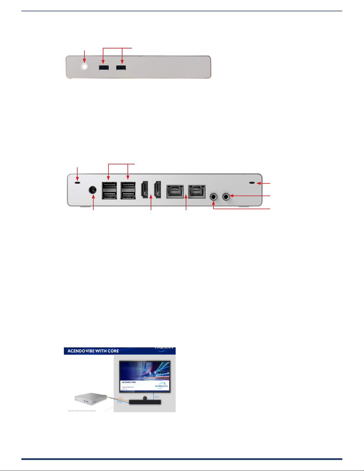
The Acendo Core front panel is intended to only be used for quick access for USB for document access and storage. The following
section lists the features on the front panel of the ACR-5100.
Power Button USB Thumb Drives
FIG. 1 ACR-5100 Acendo Core Front Panel
Power Button
When power is applied, the power button on the front panel lights up white. The device usually takes about 30 seconds to boot.
USB
The front panel features two Type-A USB 2.0 connectors for serial communication, touch screens, mouse and keyboard
functionality, USB cameras, microphones, speakers, or reading from and writing to a mass storage device, such as USB hard drive
or ash drive. (USB external hard drives may require their own power sources. The maximum current is 900mA per port).
Rear Panel Features
The following section lists the components on the rear panel of the Acendo Core.
Antenna Port
Power HDMI Output
USB 3.0 Peripherals (camera, microphone, speakers, mouse, keyboard, etc.)
Antenna Port
Stereo Audio Line Out
3.5 mm Mini-phone Jacks
Micorphone In
(to 1-2 Displays)
Dual Network Connectors
FIG. 2 ACR-5100 Acendo Core (Rear Panel)
Power
The Acendo Core power input requires +12VDC 5A from a barrel connector on an AC-DC power brick (100-240VAC) and cable
that is included with the device.
USB
The rear panel features four Type-A USB 3.0 connectors (Two double-stacked USB connectors) for mouse and keyboard
functionality, reading from and writing to a mass storage device such as USB hard drives or ash drives, microphone, speakers,
AMX’s Acendo Vibe or USB cameras such as AMX’s Sereno Video Conferencing Camera.
NOTE: USB external hard drives may require their own power sources. The maximum current allowed across all USB ports is 4W.
NOTE: The USB connectors support USB mass storage devices using either FAT, FAT32, exFAT, or NTFS le system format.
NOTE: Once a USB drive is connected and Acendo Core mounts the drive, the les on it may be accessed. If a message stating the USB drive is mounted is not
received, Acendo Core did not recognize the drive.
AMX Acendo Vibe
One of the USB ports can be connected to an AMX Acendo Vibe Conferencing Sound Bar to provide video conferencing
capabilities. The USB connection from Acendo Vibe passes microphone audio and camera video. The HDMI connection from
Acendo Core provides audio signal to Acendo Vibe while the video is passed through by Acendo Vibe to the display.
FIG. 3 ACR-5100 Acendo Core (With Vibe Connected to Rear Panel)
Dual Network Connections
ACR-5100 Acendo Core Administrators Guide
2
Page 8
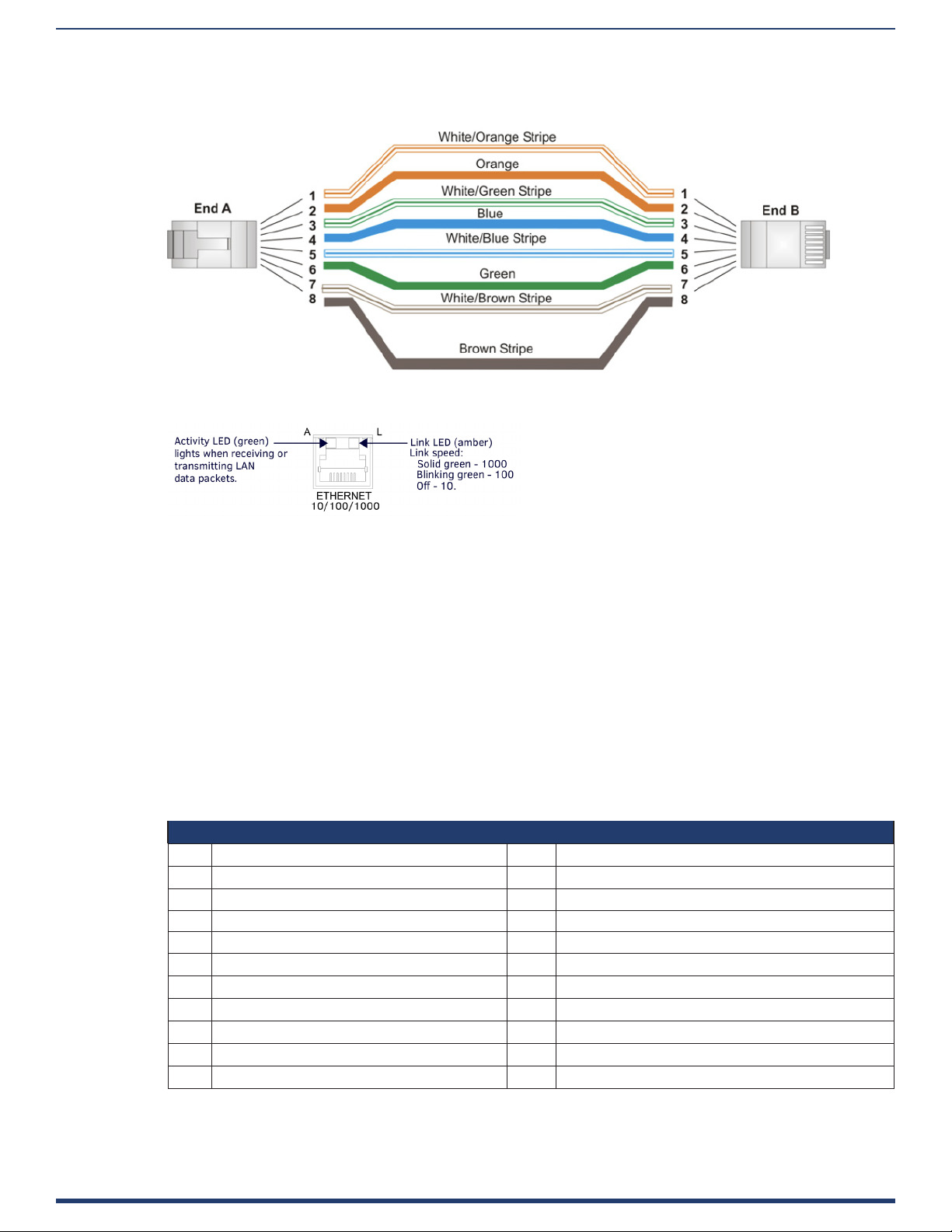
The rear panel features two 10/100/1000 Base-T RJ-45 (8P8C) LAN ports for network connection via Cat5 cable. Port2 is
disabled by default. FIG. 4 provides the pin outs and signals for the LAN connector and cable.
FIG. 4 RJ-45 Wiring Diagram
FIG. 5 describes the blink activity for the LAN connector and cable.
Overview
FIG. 5 LAN Connector / LEDs
Dual HDMI Outputs
The rear panel features dual HDMI 2.0 video outputs that can be used for dual display or extended desktop as congured by the
system administrator in the Windows Display settings. These ports support the following:
• CEC protocol for high-level control functions
• Reading the E-EDID and rst CEA Extension to determine the capabilities supported by the attached display device
• Chooses a default minimal resolution if no E-EDID is received
• Supports the following digital video output resolutions:
NOTE: Does not support dual displays with dierent resolutions. Both displays must use only one of these listed resolutions.
• 720p @ 60Hz
• 1080p @ 60Hz
• 4K @ 60Hz
• Support an audio/video interface for transferring uncompressed video data and compressed or uncompressed audio data
from the HDMI source device to a display
The following table describes the pin-out conguration of the HDMI OUT connector:
HDMI OUT Connector Pin-outs and Functions
Pin Signal Pin Signal
1 TMDS Data 2+ 11 TMDS Clock Shield
2 TMDS Data 2 Shield 12 TMDS Clock-
3 TMDS Data 2- 13 CEC
4 TMDS Data 1+ 14 Reserved, HEC Data
5 TMDS Data 1 Shield 15 SCL
6 TMDS Data 1- 16 SDA
7 TMDS Data 0+ 17 DDC/CEC/HEC Ground
8 TMDS Data 0 Shield 18 +5V Power (max 50mA)
9 TMDS Data 0- 19 Hot Plug Detect, HEC Data+
10 TMDS Clock+
FIG. 6 displays the pin locations for the HDMI connector:
Stereo Audio Line Output
ACR-5100 Acendo Core Administrators Guide
3
Page 9

Overview
FIG. 6 HDMI Pin-outs
The rear panel features one 3.5mm mini-phono connector for stereo audio output jack with the right channel on the ring and the
left channel on the tip.
Microphone Audio Input
The rear panel features one 3.5mm mini-phono connector for audio Input jack with the right channel on the ring and the left
channel on the tip. This can be used to connect to AMX’s Alero 8-channel microphone mixer for conference room meetings.
Wireless
Included in the Acendo Core device is a built-in IEEE 802.11 a/b/g/n/ac plus Bluetooth 4.0 wireless network card.
The wireless card also supports Miracast communications for screen and content sharing. MiracastTM is a groundbreaking
solution for seamlessly displaying multimedia between devices, without cables or a network connection. Users can do things like
view pictures from a SmartPhone on a big screen television, share a laptop screen with the conference room projector in real-time,
and watch live programs from a home cable box on a tablet.
Specications
The following table lists the specications for Acendo Core:
ACR-5100 Specif ications
Dimensions: 1.37” x 7.06” x 7.937” (34.8mm x179 mm x 201.6 mm) H x W x D
Weight: 1.1 lbs. (1.1 kg) TBA
Mounting Options • Surface Mount: Wall-Mount racket included
• Rack Mount Adapter: NMX-MM-RKA, Acendo Core Rack Mount Adapter (FG3211-60), not
included. The rack mount adapter is designed for use with V Style Rack Mounting Tray (FG1010720/721) and V Style Rack Mounting Shelf (FG3201-60), also not included
Regulatory Compliance: • FCC - 47 CFR Part 15, Subpart B, Class B/IEEE ANSI C63.4-2014
• IC
• CE EN 55022 Class A
• CE EN 55022 Class B
• CE EN 55024
• CE EN 60950-1
• UL 60950-1
• IEC 60950-1
• IEC 61000-4-2-2008
• C-Tick
• VCCI
• RoHS
• REACH
• WEEE
Power Requirements: • Power Consumption: 60W (Max)
• Input voltage: 100 – 240Vac
• Rated Output current: 5.417A
• Rated Output Voltage: +12 VDC
• Connector: 5.5mm barrel connector
• External universal power supply with AC-DC converter brick, 100/240 VAC, 50/60 Hz, included.
• Power Indicator: (1) LED (red/green), solid red at start of boot, blinking green during boot, solid
green after boot is complete
Environmental: • Operating Temperature: 32° to 104° F (0° to 40° C)
• Storage Temperature: –4o to 158o F (–20o to 70o C)
• Rated Altitude: 5000 Meters
• Operating Humidity: 5% to 85%, non-condensing
• Storage Humidity: 5% to 90%, non-condensing
• S/N (Signal-to-Noise) ratio, input to output, 90dB (weighted)
• Audio Total Harmonic Distortion plus Noise (THD+N), input to output, 0.01%.
ACR-5100 Acendo Core Administrators Guide
4
Page 10

ACR-5100 Specif ications
Control NetLinx:
• Master Code: URL, Auto, Listen
• ICSP Security: Yes
RS-232:
• Supported through USB using USB-DB9 adapter cable
Operation Button:
• Quick press: Sleep
• Press-and-hold: System Settings
Port Usage • 8888 TCP Group Manager
• 1319 TCP Remote Logging
• 23 TCP Telnet logging
• 80 TCP Default port for AmxShare
• 1319 UDP NetLinx
• 587 Email Port
Processor: • a quad core Intel Celeron SoC
• x64 architecture and instruction set of 1.6 GHz which contains a burst option to 2.24 GHz
Operating System: • Windows 10 IoT Enterprise
Memory: • 4GBRAM
• 120GB solid state drive (SSD) as the primary internal storage media
Supported Calendar
Systems:
• Microsoft Exchange 2013 SP1 or higher
• Microsoft Exchange 2016
• Exchange Online (Oce 365)
Bluetooth: • 802.11a/b/g/n/ac standard protocol and frequency bands
• Bluetooth 4.0
• Meets Bluetooth SIG standards
• Bluetooth range (Min): 10 meters
HDMI Out: Two HDMI 2.0 Type A connectors for video output:
• Supports CEC protocol for display control
• HDCP specication 1.4
Analog Audio: One 3.5mm mini-phono connector for stereo output:
• Supports two channels (left/right)
• Output Connection: 3.5 mm stereo audio jack
• Output Level (Max): 0 dBV (1 Vrms)
• Output Impedance: 100 Ohms
• Frequency Response: 20-20 kHz
• Dynamic Range: 90 dB
One 3.5mm mini-phono connector for single sided balanced audio input:
• Supports two channels (left/Right)
• Input Level (Max): 0 dBV (1 Vrms)
• Sampling frequencies: 32 kHz, 44.1 kHz, 48 kHz at both 16 bits and 24 bits
• Input impedance: 10k Ohms
Ethernet: Two 10/100/1000 Base T LAN ports for network connection via Cat5 cable.
• Connection: (2) RJ-45, Auto MDI/MDI-X
• Link/Act Indicator: (1) LED (green),
a. on when link is up
b. blink o for packet activity
c. o when link is down
• Speed Indicator: (1) LED
d. solid green when the speed on the link is 1000 Mbps
e. solid amber at 100 Mbps
f. o when the speed is 10 Mbps
• Support half and full-duplex
• Support IEEE 802.1X port-based Network Access Control (PNAC)
• Support WoL (Wake-on-LAN) feature (system awakens by a network message)
Overview
ACR-5100 Acendo Core Administrators Guide
5
Page 11

Overview
ACR-5100 Specif ications
USB: USB connectors support connecting peripheral devices such as a USB keyboard or mouse, a mass
storage device such as a USB hard drive or ash drive, touch screens, or USB Cameras (UVC1.4).
Connection:
• Two USB 2.0 Type A, 500mA, 480 Mbps
• Four USB 3.0 Type A, 900mA, 4.8 Gbps
• +5V Current Output (Max): 4 W total across all USB connections
Wireless Keyboard & Mouse:
• Supports 2.4 GHz RF wireless keyboard and mouse using wireless dongle (not included)
Applications: • Viewers for PowerPoint, Word, Excel, and PDF document
• Viewers for images and videos
• Microsoft Edge web browser
• Skype for Business Client (note: customers will need to supply a Skype for Business user account
for each Acendo Core)
• Microsoft Teams
• Zoom Meeting
Optional Accessories: • Acendo Vibe:
ACV-5100 FG4151-00 GR/BL
ACV-5100 FG4121-00 GR/BL
• CBL-HDMI-FL, HDMI High Speed Flat Cable with RedMere® Technology (FG10-2180-16)
• CBL-USB2-FL-16 (FG10-2220-16) 16ft USB 3.0 Flat Cable
• CBL-USB2-FL-33 (FG10-2220-33) 33ft USB 2.0 Flat Cable
• CBL-USB-FL2 (FG10-2197-16) 16ft USB 3.0 My Turn Ready Flat Cable
• CBL-ETH-FL2-16 (FG10-2194-16) 16ft CAT6 Ethernet Cable
• CBL-HDMI-FL2-16 (FG10-2192-16) 16ft HDMI My Turn Ready Flat Cable
• AVB-VSTYLE-RMK-1U V-Style Box Tray (FG1010-720)
• AVB-VSTYLE-RMK-FILL-1U,V-Style Box Tray with Fill Plates (FG1010-721)
• NMX-VRK V-Style Rack Shelf (FG3201-60)
• NMX-MM-RKA (FG3211-60)
ACR-5100 Acendo Core Administrators Guide
6
Page 12
Overview
Acendo Core Welcome Screen
The Acendo Core Welcome screen provides users with room booking abilities, a 48 hour scheduler view, Admin sign on feature.
The Admin username and password must be entered to view or change any of the system settings.
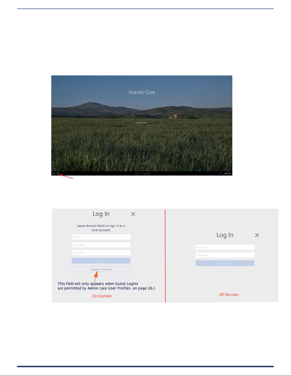
User Login
Users can access the user Home screen by clicking on the blue Use Room Now button at the center of the welcome screen (FIG. 7).
Admin Login
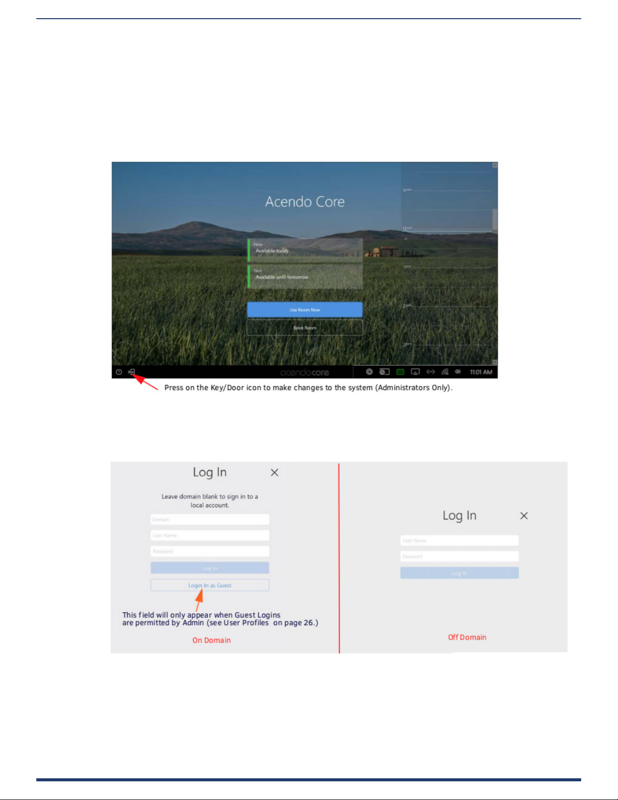
1. Administrators can login by clicking on the Key/Door icon in the bottom left of the screen (FIG. 7).
Administrators press on the Key/Door icon to make changes to the system).
FIG. 7 Acendo Core Main Screen
2. The login screen appears (FIG. 8).
NOTE: The Domain eld will not be visible if unit is o domain. Additionally, Log In and Login In as Guest will not be visible if o
domain.
FIG. 8 Login Screen - On Domain (left) and O Domain (right)
3. Log into the session on the Acendo Core using Admin credentials:
• Username -coreadmin
• Password - c0r3@dmiN (c “zero” r3@dmiN)
NOTE: Remote access into Rome (RDP) is not supported. You can use the RDP client on Rome to remotely login and access other
non- Rome PCs. Due to Rome’s ecosystem only local single sign-on is allowed.
ACR-5100 Acendo Core Administrators Guide
7
Page 13
Overview
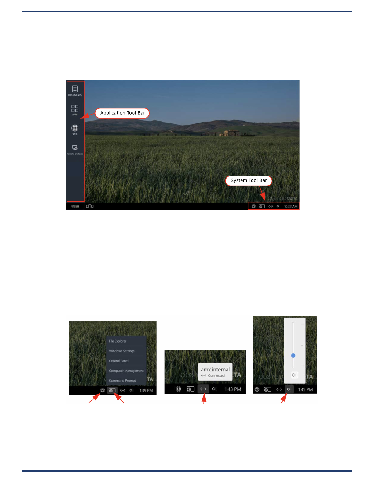
Acendo Core Home Screen
The Acendo Core Home screen provides users with access to default applications and up to four additional Admin assigned App
Favorites in the Applications tool bar (FIG. 9). Some features in the System Tool Bar are not available to non Admin users such as
System Settings and the Windows control panel dened later in this chapter.
1. After an Admin user Login, the system displays the following screen with an app tool bar down the left side and additional
settings lower right.
FIG. 9 Administrator Session Screen
System Tool Bar
The System Tool bar provides at-a-glance system statuses and for Administrators, access to system settings (see Acendo Core
System Settings section on page 15) and System Shortcuts (FIG. 10). The System Shortcuts are standard Windows locations used
to make system-wide changes. Shortcuts are as follows:
• File Explorer - Opens a view of le folders and network locations.
NOTE: Both guest and domain users are able to view Program les (though they are not able to edit these les), create folders on
the C drive and write to the C drive. Files and folders written to the root of the C drive that were not there at the beginning of a
session will, in fact, be purged upon logout.
• Windows Settings - Opens Windows Settings to make system changes to privacy, accounts, network, devices, etc.
• Control Panel - Opens the Windows system Control Panel to make changes to network locations, hardware changes, etc.
• Computer Management opens the Windows system Computer Management screen to view performance, folders, etc.
• Command Prompt - opens a Command Prompt window for DOS users/
System Settings System Shortcuts Wired Network Status System Volume Options
FIG. 10 System Toolbar
ACR-5100 Acendo Core Administrators Guide
8
Page 14
Overview
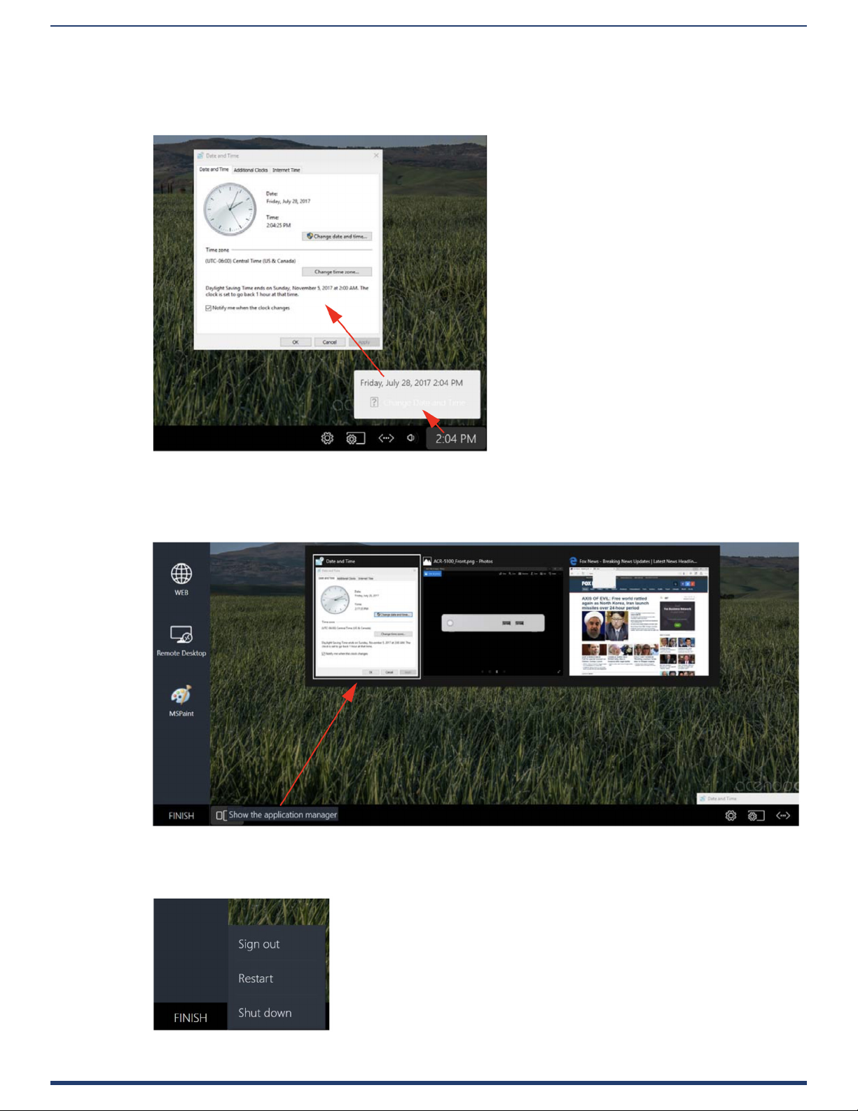
System Clock
Clicking on the System time will bring up the Day of the Week, Date and Time view as shown in FIG. 11. Furthermore, click on the
Change Date and Time link to bring up the Windows System clock to make changes.
Click on Change Date and Time to bring
up the Windows clock.
Click on the time to bring up this view.
FIG. 11 System Clock
Application Manager
The Application Manager is used to show the current applications that have open windows FIG. 12. Users can then select one of
the apps to reopen, or close each window by selecting the “X” in the top right corner or each app.
FIG. 12 System Clock
Finish - Log O
To exit a session, users should select the Finish button in the bottom right of the screen and select from the options shown (FIG. 13).
FIG. 13 Finish Session Options
ACR-5100 Acendo Core Administrators Guide
9
Page 15

Overview
When users and guests logo the system the following user folders are deleted for ALL users:
• CD Burning
• Cookies
• Desktop
• Documents
• Downloads
• Music
• Pictures
• Public Desktop
• Public Documents
• Public Downloads
• Public Music
• Public Pictures
• Public Ringtones
• Public Videos
• Ringtones
• Videos
And the following for the Core Guest account only:
• Application Shortcuts
• Favorites
• History
• Internet Cache
• Links
• Recent
• Saved Searches
• Search History
In addition, for all accounts but Core Admin, les or folders created in the root of the C:\ drive will be deleted. This only applies to
the root and does not track into any sub-folders of C:\.
Window Service Plan Information
The following link provides Microsoft’s overview of Windows as a service:
https://docs.microsoft.com/en-us/windows/deployment/update/waas-overview#servicing-channels
Acendo Core Release 1 service plan:
1. Acendo Core is aligned with the Microsoft’s Semi-Annual Channel.
2. Acendo Core will utilize a group Policy enabling the full 365 day deferment period of all feature updates (from the date they
are released) in order to support feature update integration.
ACR-5100 Acendo Core Administrators Guide
10
Page 16
Installation
Overview
The Acendo Core (ACR-5100) is passive cooled without the need for fans and constructed of silver powder-coated sheet
metal. Its dimensions are 1.37” x 7.06” x 7.937” (34.8mm x179 mm x 201.6 mm) H x W x D and requires 1RU slot when
mounted in a 19” rack. The device is equipped with feet for tabletop usage. See Installation on page 11 for mounting
instructions. The recommended installation locations are:
• Wall mounted behind a display
• Mounted underneath a table
• Inside credenza
• Out on top of the credenza
• In a rack shelf.
Installing Acendo Core is a quick and simple process. Before connecting the ACR-5100 to its peripheral devices and powering the
device, be sure to mount the device using the desired method detailed below.
Installation
What’s in the Box?
The Acendo Core Meeting Collaboration System includes the following accessories:
• Power supply/cord
• 1 Mounting Plate and 2 Stand-o Screws
• Safety Instructions and a Quick Start Guide
Installation
Physical Installation
To install Acendo Core, the following items are needed:
• 1 HDMI cable (Type A male)
• thernet cable
• 1 HDMI touch screen or HDMI monitor with USB keyboard and/or mouse
• Mounting screws are needed for wall or under desk mounting options
Acendo Core can be mounted using the included mounting plate for wall or under desk mount or can be used as a table-top
device.
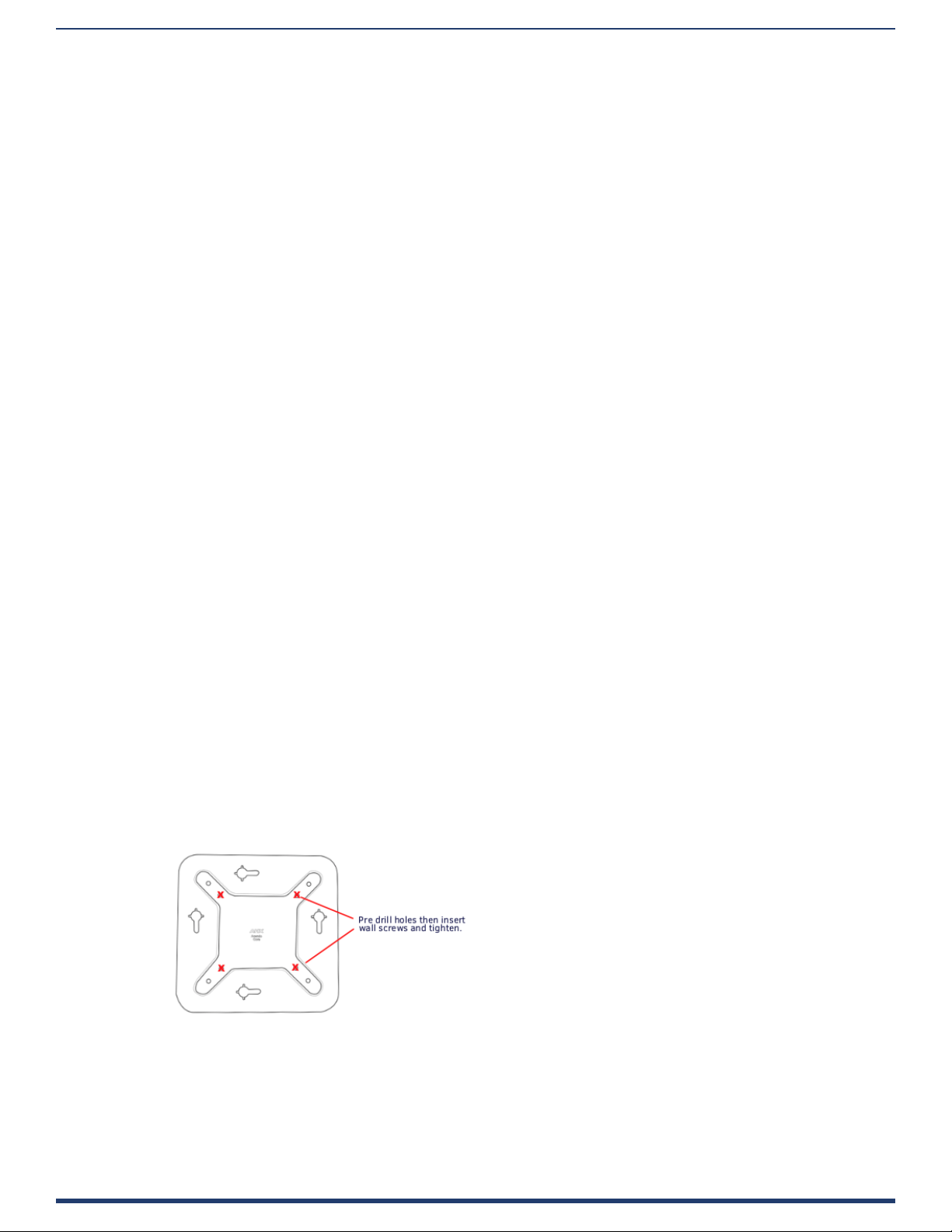
Attach Mounting Plate
1. Using the mounting plate as a template, place it into the desired position and mark four of the wall screw holes with a pencil.
Note: If mounting on a wall, a level can be used to set the plate level for aesthetics.
2. Pre drill the holes for your wall screws.
Note: Use a drill bit smaller in diameter than your wall screws.
3. Place the plate back onto the mounting surface, insert wall screws and tighten.
FIG. 14 BACKPLATE - INSERT SCREWS AND TIGHTEN
Attaching to Mounting Plate
1. Insert the included stand-o screws into two adjacent holes on the bottom. Align the stand-o screws on the Acendo Core
unit with the slotted holes in the plate and push through. Slide to lock.
ACR-5100 Acendo Core Administrators Guide
11
Page 17
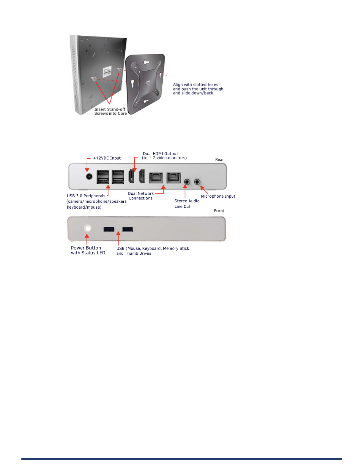
FIG. 15 ATTACH STAND-OFF SCREWS, INSERT THROUGH BACKPLATE
Connections
FIG. 16 displays the ports provided on Acendo Core.
Physical Installation
FIG. 16 ACENDO CORE CONNECTIONS
ACR-5100 Acendo Core Administrators Guide
12
Page 18
Physical Installation
Acendo Core Power Up
This section describes the required steps to successfully power up the Acendo Core ACR-5100. FIG. 17 provides references
to the Acendo Core rear access ports that will have connections made to peripheral devices, monitors, and power.
FIG. 17 ACR-5100 Acendo Core (Rear Panel)
Connecting to a Video Output
The ACR-5100 uses standard HDMI cabling to connect to a monitor/projector.
1. Use an HDMI cable to connect the HDMI Port1 on the Acendo Core rear panel to the display monitor.
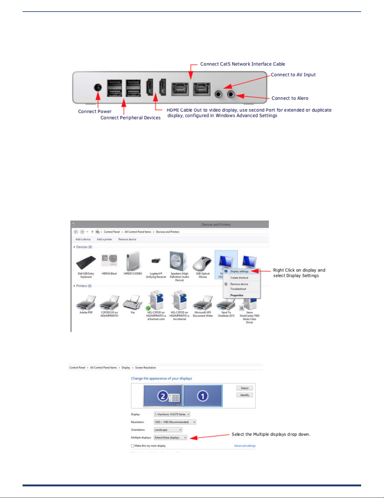
2. To use Dual displays, use an HDMI cable to connect a second monitor to the additional HDMI Port on the rear panel. Some
conguration will be required in Windows to set up the dual displays. Go to the Windows Control Panel as shown in FIG. 18.
Note: Does not support dual displays with dierent resolutions. Both displays much use only one of these listed resolutions:
– 720p @ 60Hz
– 1080p @ 60Hz
– 4K @ 60Hz
FIG. 18 Windows Control Panel - Devices and Printers
3. Right click on the display to select Display Settings. FIG. 18 appears. Select the Extend these displays options to combine
two displays to create a larger desktop.
FIG. 19 Windows Control Panel - Display Settings
ACR-5100 Acendo Core Administrators Guide
13
Page 19
Physical Installation
Connecting a Keyboard and Mouse
Acendo Core front and rear panels each feature Type-A USB ports for mouse and keyboard functionality, two on the
front and four on the rear. The ports may also be used for reading from a mass storage device, such as a USB hard drive
or flash drive. (USB external hard drives may require their own power sources. The maximum power allowed across all
USB ports is 4W.)
NOTE: In addition to a directly connected USB keyboard and mouse, the ACR-5100 also supports using a 2.4 GHz RF wireless
keyboard and mouse using a wireless dongle. Bluetooth devices are NOT supported.
NOTE: The USB connectors support USB mass storage devices using either FAT FAT32, exFAT, or NTFS le system format.
NOTE: Once connected to a USB drive and Acendo Core mounts the drive, the les on it may be accessed. If a message stating the
USB drive is mounted is not received, Acendo Core did not recognize the drive. A storage device’s contents are not accessible if the
device is connected while another storage device occupies a USB port. If a rst USB drive is connected, mounted, and unmounted, a
second USB drive will still not be recognized unless the rst USB drive is removed from the Acendo Core device.
Connecting Power
Connecting power to the ACR-5100 requires the AC-DC power brick and cable provided with the device.
1. Insert the barrel plug into the ACR-5100 power input marked +12VDC 5A.
2. Connect the power brick to an AC outlet (100-240VAC) using a standard power cord.
3. Verify that the front panel led lights up. When power is applied, the POWER LED on the front panel lights up white. The device
usually takes 20-30 seconds to boot. When booting is complete, the ACR-5100 opens to the Acendo Core desktop (FIG. 20
FIG. 20 Acendo Core Desktop
Disconnecting Power
To disconnect power from the AcendoCore unit, follow these steps:
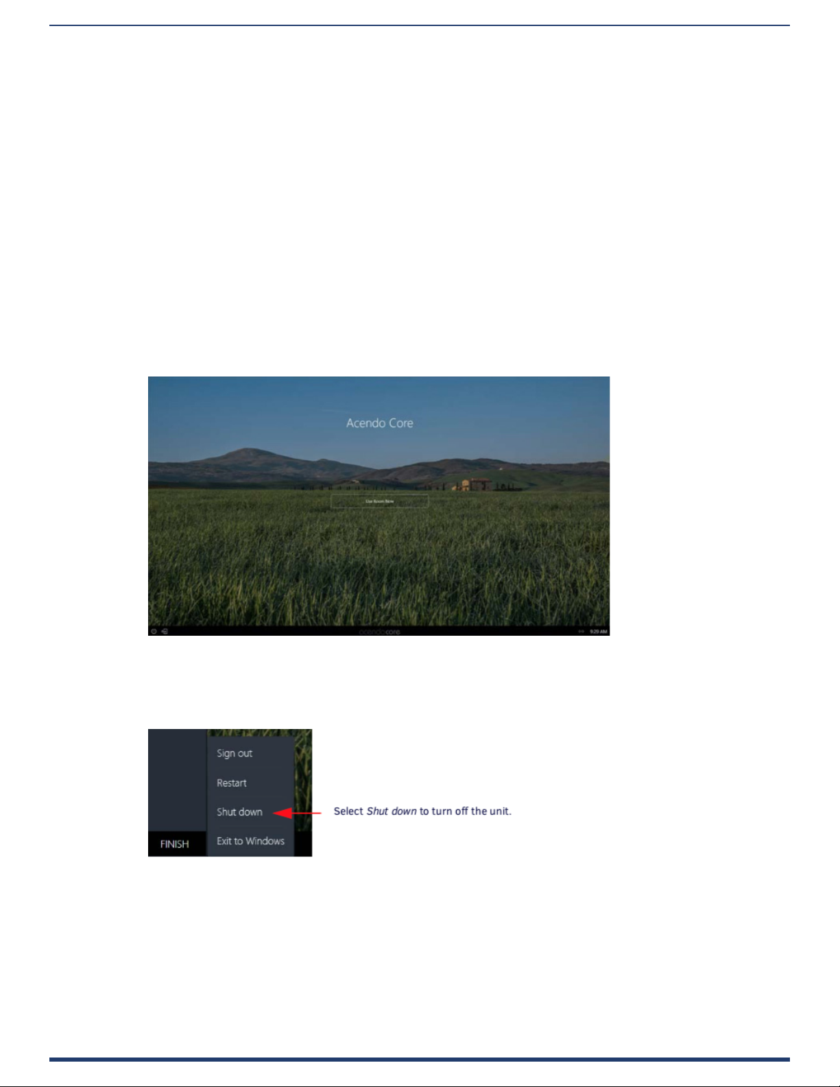
1. Click on FINISH in the lower right-hand corner to bring up the menu (FIG. 20).
FIG. 21 Acendo Core Finish Menu
2. Select Shut down to allow the unit to close its apps and turn o.
3. Remove the wall plug from the AC outlet.
4. Unplug the barrel plug from the rear of the units input marked +12VDC 5A.
ACR-5100 Acendo Core Administrators Guide
14
Page 20
Acendo Core System Settings
Login
The Acendo Core System Settings are only available to system Administrators. The Admin username and password must
be entered to view or change any of the system settings.
1. Press the Key/Door icon in the bottom left of the screen next to the Power Icon to bring up the login screen.
Acendo Core System Settings
FIG. 22 Acendo Core Main Screen
2. The login screen appears (FIG. 23).
NOTE: The Domain eld will not be visible if unit is o domain. Additionally, Log In and Login In as Guest will not be visible if
o domain
FIG. 23 Login Screen - On Domain (left) and O Domain (right)
3. Log into the session on the Acendo Core using Admin credentials:
• Username -coreadmin
• Password - c0r3@dmiN (c zero r 3@dmiN)
ACR-5100 Acendo Core Administrators Guide
15
Page 21
Acendo Core System Settings
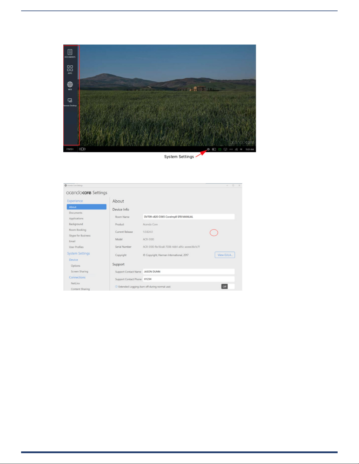
4. After an Admin user Login, the system displays the following screen with an app toolbar down the left side and
additional settings lower right.
FIG. 24 Acendo Core Main Screen
Experience
1. Clicking on the Acendo Core Settings button brings the user to the About Acendo Core screen.
FIG. 25 Acendo Core Settings - About
Refer to a section listed below for complete details on specic settings:
• About on page 17
• Documents on page 17
• Applications on page 17
• Background on page 21
• Room Booking on page 21
• Skype for Business on page 29
• Microsoft Teams on page 31
• Email on page 31
• Zoom Meeting on page 32
• User Proles on page 32
• Device - Options on page 33
• Screen Sharing on page 40
• Share Internet Connection on page 41
• NetLinx on page 42
• Language on page 43’
• Content Sharing on page 43
ACR-5100 Acendo Core Administrators Guide
16
Page 22
Acendo Core System Settings
• System - Acendo Core Updates on page 45
• Import/Export on page 46
• System Recovery and Backup on page 48
About
Selecting About (FIG. 25 above) will display this specic Acendo Core unit’s conguration such as:
• Room Name - Assign a room name to this unit so it can be uniquely identied.
• Product - Static information dening this unit as an Acendo Core
• Model - Static information dening this model as ACR-5100
• Serial Number - Serial number of this unit. Each Core unit will have a unique number assigned from the factory.
• Copyright - AMX copyright protecting interests of the company.
• Support Contact Name and Contact Number - Add an AMX or Dealer contact information for easy access to this
information should issues arise.
• Export Diagnostics - Selects a folder to save diagnostics to on your local system.
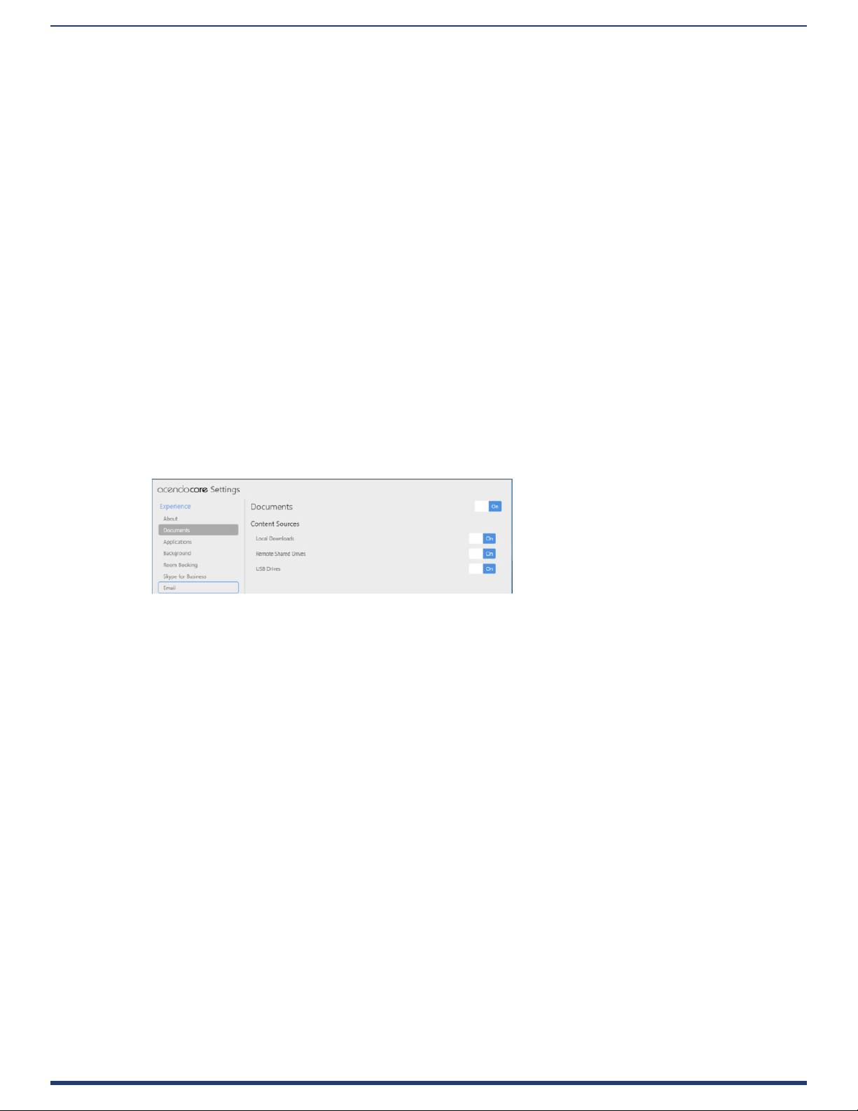
Documents
Select Documents to bring up the following options:
• Documents - Enable or disable users ability to access documents for display from Local Downloads, Remote Shared
Drives or USB Drives. Disabling documents will remove the document icon from the left tool panel.
NOTE: The most straightforward method for an Admin to disable USB devices is using group policies. See Wireless Presentation
Issues section on page 63
• Local Downloads - Enable or Disable access to this source.
• Remote Shared Drives - Enable or Disable access to this source.
• USB Drives - Enable or Disable access to this source.
FIG. 26 Acendo Core Settings - Documents
Applications
1. The Applications section enables Admins to turn access to Applications on or o, add more apps to the device, or
specify default Favorites (up to four) that will be displayed on the Home screen.
ACR-5100 Acendo Core Administrators Guide
17
Page 23

FIG. 27 Acendo Core Settings - Applications
Acendo Core System Settings
ACR-5100 Acendo Core Administrators Guide
18
Page 24

Acendo Core System Settings
Applications Listed
Applications Listed shows all of the applications that have been added to this device. Default apps are:
• Skype for Business
• Web Browser
• Media Player
• Remote Desktop
• Calculator
• Microsoft Teams
• Zoom Meeting
Follow these instructions to add additional applications to this device.
1. Hovering over the Add Application button will highlight it, Select it to add an application. The following dialog pops up.
FIG. 28 Acendo Core Settings - Applications - Add Application
2. Enter a name for the Application.
3. Click Browse to locate the executable le (.exe) to add the app.
4. This eld is for application command line arguments so it’s application dependent. If the application supports
arguments the user can use this eld to pass them at execution startup (i.e., open a document when launching Word).
Web Apps Listed
Web Apps Listed will display any Web Applications that were added to this device which could consist of corporate programs
on local servers.
1. To add an application from the Internet, Click on the Add Web App button. The pop up shown in FIG. 29 shows a Web
App dialog,
2. Enter a Name and the URL address of the app and click OK.
FIG. 29 Acendo Core Settings - Applications - Add a Web App
3. The Web App will now be displayed in the list.
ACR-5100 Acendo Core Administrators Guide
19
Page 25

Acendo Core System Settings
Application Favorites
Up to four favorite apps may be added here that will display their icons on the Home screen left banner (FIG. 32).
NOTE: When changing the Applications Favorites, the tool bar may not reect the current changes until the Admin user ends
session and comes back in.
FIG. 30 Application Favorites
1. Click on the Drop Down menu for each of the four favorites and select an application from the installed apps in the list
(FIG. 31).
FIG. 31 Acendo Core Settings - Applications - Add a Favorite App
2. The Favorite Application icons are then arranged on the home page as shown in (FIG. 32).
FIG. 32 Acendo Core Settings - Applications - Favorites Icons
NOTE: If a Favorite is skipped, the next Favorite will show in its place on the home screen so no blank spaces are left in between.
ACR-5100 Acendo Core Administrators Guide
20
Page 26

Acendo Core System Settings
Background
The Background tab enables administrators to assign a dierent image to the Welcome/Home screen.
1. Either drag-and drop and image to the center of the dotted lines, or browse to select an image that has been saved locally.
FIG. 33 Acendo Core Settings - Background
Room Booking
The Room Booking tab is where the Administrator will provide vital data to congure the corporate calendar, group this
device with other rooms, and set the default scheduling settings. In FIG. 34, Room Booking is switched O (note that
Calendar Provider and Room Grouping are grayed out.)
FIG. 34 Acendo Core Settings - Room Booking - O
ACR-5100 Acendo Core Administrators Guide
21
Page 27

Acendo Core System Settings
2. With the Room Booking turned O, the Home screen appears as shown (FIG. 35). Note the lack of a calendar icon.
FIG. 35 Home Screen with Room Booking Turned OFF
3. Click on the Room Booking switch to toggle it to On. This will take several seconds to complete and new options will appear.
FIG. 36 Acendo Core Settings - Room Booking On Options
Calendar Provider
Enter the following information to congure each Acendo Core user and room for use with Microsoft Exchange / Oce 365:
• Calendar Provider - Choose from the drop-down list: Microsoft Exchange or Oce 365
• Server URL - enter the secure URL of the Exchange server
NOTE: The Exchange Server URL should appear as: https://SERVERNAME/EWS/Exchange.asmx
NOTE: The default Oce 365 Server URL should appear as: https://outlook.oce365.com/EWS/Exchange.asmx
• Username - Enter a valid name for a user with access rights that are appropriate for the room specied in the Calendar
Email ID eld (see below). The Username must include the fully qualied domain name.
– Example: JaneDoe@acme.onmicrosoft.com
NOTE: The Username and Calendar Email ID should always be the Full SMTP email address associated with a mailbox: USERNAME@
DOMAIN and RESOURCE@DOMAIN.
• Password - This is the password to access the Exchanger server.
• Calendar Email ID - Enter the email address for a valid room. The Calendar Email ID must include the fully qualied
domain name.
– Example: ConfRoom1@acme.onmicrosoft.com
ACR-5100 Acendo Core Administrators Guide
22
Page 28

Acendo Core System Settings
NOTE: The Calendar Email ID eld is the only eld that is unique to each room: “Provider”, “Server URL”, “Username”, and
“Password” are the same across all rooms in the system.
• Connection Status - Current status of the Acendo Core connection to the calendar server.
• Debug Diagnostics - Used to provide Engineering logging capabilities. Turn the diagnostics O during normal use.
Room Grouping
Room Grouping is optional. Creating a group can alleviate congestion when one device is deemed room grouping a Master and
other devices are Members of its group. The Master will poll the server for updates and members will poll the master device which
enables them to browse schedules of all rooms in a Group. When a room is occupied, users can browse other rooms and schedule
a meeting in any of the rooms in the group.
NOTE: Core devices must have port 8888 open for in-bound grouping communication to succeed. Otherwise requests will be blocked
by the rewall.
There is a third option for room grouping, None. This option would only be used if the unit isn’t part of a group, typically this
would be a boardroom.
NOTE: Acendo Core and Acendo Book can be in the same room group, and if they are, they should be part of the same group.
Conf igure Master
1. Making the device a Master enables the options shown (FIG. 37).
FIG. 37 Acendo Core Settings - Room Booking Group Master
2. If desired, enter a new Master Username and/or Password. To change the Password, click on the Edit button.
Congure Master
1. Click on the View Members button to view the other room members for this group. If needed, congure this or other rooms
as a Member using the options shown below.
2. Enter the Master device IP address or Hostname.
3. The Connection Status will change to Connected in green once the credentials are entered properly.
ACR-5100 Acendo Core Administrators Guide
23
Page 29

Acendo Core System Settings
Settings
The Settings section allows Administrators to customize the defaults for the room booking on the main screen.
Default Meeting Length
Clicking on the Default Meeting Length will bring up the following options:
• 15 minutes
• 30 minutes
• 1 hour
FIG. 38 Acendo Core Settings - Room Booking Page 2
4. Select a default meeting length from the drop-down list. When a user books the room, the system will block out that period of
time (FIG. 39).
NOTE: If booking a meeting now within the rst 5 minutes of the current period, the system will book the remaining time of that
period. If booking a room now after the rst 5 minutes in this period, the system will book through the current period and an
additional 15 minutes interval if the room is available.
Default Meeting Increment
1. Select a Default Meeting Increment from the drop-down to bring up the following options:
• 15 minutes
• 30 minutes
• 1 hour
This will aect the “Book For” time when booking a room. If the default Meeting Length is 15 minutes and the Default Increment is
1 hour, the booking will increase an hour each time the user increases the meeting time using the arrow button.
FIG. 39 Acendo Core - Book Room
Default Meeting Subject
1. Enter a subject for meetings booked in this room. This can be changed by the user when they book a room as along as
Privacy mode is turned OFF. Users may also leave comments if this condition is met.
ACR-5100 Acendo Core Administrators Guide
24
Page 30

Acendo Core System Settings
Require Meeting Pin Code
If a conference room needs to be set aside for certain users, a Pin Code can be set that requires users to enter it before they can
book a meeting.
1. To require a Pin Code for this room, click on the switch to toggle it to ON. The system provides a 10-key for entering the Pin
Code (FIG. 40).
FIG. 40 Admin Settings - Room Booking - Set a Pin Code
2. Enter a 4-digit Pin Code for the room and click Submit.
3. Now when a user tries to book the room, they can go through the normal process until they hit Reserve. Now the ten key will
reappear requiring the code to reserve the room (FIG. 41).
FIG. 41 Acendo Core - Book Room - Pin Required
Read Only Mode
Read only mode is for oces that do not want to book the rooms from the Acendo Core. Users can only use their Outlook interface
to book rooms.
1. To make the room Read Only Mode, click on the switch to toggle it to ON (FIG. 42).
FIG. 42 Admin Settings - Room Booking - Read Only Mode
ACR-5100 Acendo Core Administrators Guide
25
Page 31

Acendo Core System Settings
2. Now when users enter a room they will no longer see the Book Room options. They may however still Use Room Now as
shown in (FIG. 43).
FIG. 43 Book Room in Read Only Mode
Force Booking
In some instances, Administrators may wish to force users to book a room as opposed to using the room without booking it.
Reasons to use Force Booking might be for logistics, to determine how often rooms are being booked, etc.
1. To enable Force Booking, click on the switch to toggle it to ON (FIG. 44).
FIG. 44 Force Booking a Room
2. The users will see the same screen when they walk into a room, but when they select Use Room Now, they will be shown the
Book Room Now pop-up requiring them to book the room (FIG. 45).
FIG. 45 Book Room in Force Booking Mode
ACR-5100 Acendo Core Administrators Guide
26
Page 32

Acendo Core System Settings
Privacy Mode
Privacy Mode eliminates the users ability to enter a meeting subject or comments, leaving a Privacy Meeting Subject that the
Administrator assigns.
1. To make the meetings Private only, click on the switch to toggle it ON (FIG. 46).
FIG. 46 Privacy Mode
2. A new eld Private Meeting Subject appears. Enter a subject that all meetings will use, such as Private Meeting (default).
3. Now when users Book a Room, the Subject and Comments are grayed out. (FIG. 47).
FIG. 47 Book Room in Private Mode
4. Likewise, the main view others will see will just refer to a Private Meeting (FIG. 48).
FIG. 48 Main Screen with a Private Mode Meeting
ACR-5100 Acendo Core Administrators Guide
27
Page 33

Acendo Core System Settings
Show Day Calendar
The Day Calendar provides up to a 48hr view of today and tomorrow. It is on a slider on the right side of the main screen (FIG.
49). It can be disabled using Show Day Calendar.
FIG. 49 Day Calendar View
5. To disable the Day Calendar, click on the switch to toggle it OFF (FIG. 50).
FIG. 50 Room Booking - Day Calendar Enable/Disable
6. Now the main screen is clear of the calendar (FIG. 51). Calendar can also be toggled on/o by clicking on the icon shown.
FIG. 51 Main Screen without Day Calendar
ACR-5100 Acendo Core Administrators Guide
28
Page 34

Acendo Core System Settings
Skype for Business
Use the Skype for Business settings to congure how the meeting room handles Skype calls. Acendo Core supports One-Click
Meeting Start for the following web conferencing systems:
• Skype for Business (on-premise where the server is maintained locally by the company using it)
• Skype for Business (Oce 365, o-premise where the server is maintained o-site by someone the company has
contracted with)
• For a list of ports Skype For Business uses, refer to the “client” section of :
https://technet.microsoft.com/en-us/library/gg398833.aspx?f=255&MSPPError=-2147217396
Prerequisites
This procedure assumes that existing Skype account logins exist for the room. Currently the administrator must enter the full
username@domain for Skype for Business to auto discover the SIP address through DNS. It is up to the IT’s installation of Skype
for Business for what needs to be entered in these elds. Ensure the accounts are in place as follows:
Oce365
• Username: [username]@[servername].onmicrosoft.com
• Password: [admin dened]
Exchange
• Username: username@domain
• Password: [admin dened]
FIG. 52 Skype for Business Settings
1. Select the On/O switch to toggle the Skype feature On.
One-Click Meeting Join
2. Select Auto-Start Meeting to toggle it to On so the booked Skype meeting starts the conference automatically.
Sign-in Address
3. Enter the account email address for this room.
Password
4. Enter the account password for this room.
Test Connection
The Skype for Business “Test” button helps Administrators verify entered settings work in our environment. If the Skype for
Business client is already running in the background, the button’s results may not be completely accurate.
NOTE: Be sure to delete all “Sign In Info” from the Skype for Business Client for the test to be accurate.
5. Click on the settings Icon shown circled in FIG. 53 and select File – Sign Out to sign out from Skype for Business.
FIG. 53 Skype for Business Test Login Progression
ACR-5100 Acendo Core Administrators Guide
29
Page 35

Acendo Core System Settings
6. Click on Delete my sign-in info to delete the user information from the Skype for Business Client (FIG. 54).
FIG. 54 Skype for Business Test Login Progression
7. Click on Test to launch Skype for Business to check the validity of the credentials. The system will go through a progression
of windows until it fails and asks for proper credentials or succeeds as shown in FIG. 55.
FIG. 55 Skype for Business Test Login Progression
Unexpected Behaviors
• Visually Seeing Wrong Username - Scenario: If the Admin has recently updated the Skype for Business Sign-
in Address, or a domain user logged in as an account other than the Acendo Core’s settings in their previous
session, the Sign-in address seen in the client will be different than the actual account being signed in. On each
new session start, Acendo Core will use it’s settings to override the previous state of the client, ensuring that the
Admin experience is preserved.
Fix - Although a user may be confused, nothing is actually wrong with the system and no ill side eects will result from
visually seeing a dierent sign-in address than the account being signed in.
• Being Prompted To Enter Password To Log-in - Scenario: At session start, if connection to the Skype for Business
server is unavailable, the client will show the password eld as blank and awaiting user input.
Fix/Workaround - If the session has a scheduled Skype for Business meeting as it’s context, a “Start Web Conference”
button will be available in the Meeting Status Dialog accessible from the system task bar. Clicking this button when the
server becomes available will restart the process of logging in and entering the scheduled meeting.
If there is no Skype for Business meeting for the session, the user must exit session and re-enter when the server
becomes available again.
• Being Prompted For Credentials To Access Address Book - Scenario: The Skype for Business client has successfully
logged in, however when attempting to search for other accounts the user is prompted to re-enter credentials.
Fix: Please search the latest Microsoft documentation to ensure all forwarding addresses have been correctly congured
on the domain controller, exchange server, and/or Skype for Business server.
• Early Start to SFB Meeting Can Put User in Wrong Meeting - In a default Skype for Business installation, the client
application attempts login with the Windows profile prior to any other requests. This means domain users who sign
ACR-5100 Acendo Core Administrators Guide
30
Page 36

Acendo Core System Settings
into Acendo Core, will be logged into the Skype for Business client under their own account. AMX recommends
enforcing Skype for Business’s GPO (Group Policy) setting “Require Logon Credentials” to allow Acendo Core
to handle login for all users on the unit. This will unify the experience and have the unit always sign in as the
configured credentials provided in the Acendo Core Settings.
• Domain User SFB Sign-in Overrides Core SFB Sign-in On Log-in - In some versions of Skype for Business, user
accounts are set up with an undesirable default setting for their meeting entry Id. If the option is set to “My
dedicated meeting space”, every meeting booked by that user will share the same Id, and unintended behavior
can occur. We recommended making the default option for all users be “A new meeting space” so that each Skype
meeting has a unique meeting entry Id. Follow this (https://support.office.com/en-us/article/Set-options-for-
Lync-Meetings-f628a0fe-6b94-469b-975c- 8852a19bddad) link and reference the section “Where do you want to
meet online?” for more information.
Microsoft Teams
• Acendo Core supports One-Click Meeting Start for Microsoft Teams meetings.
• Use the Room Booking settings to congure how Acendo Core connects to Microsoft Teams meetings
• Microsoft Teams application is installed by default and is listed under Applications in the Acendo Core Settings, and
under APPS on the menu bar when in a session.
• There are no specic Microsoft Teams settings in the Acendo Core settings, connections to Microsoft Teams meetings
are made when scheduling the meeting.
FIG. 56 Core Teams Invite
Zoom Meeting
Use the Zoom Meeting settings to congure how Acendo Core connects to Zoom meetings.
Zoom Meeting supports the following settings:
• Sign-in Address
• Web Domain
• SDK Key
• SDK Secret
After completing the settings click Test to test the connection to Zoom Meetings
ACR-5100 Acendo Core Administrators Guide
31
Page 37

Acendo Core System Settings
FIG. 57 Zoom Meetings
Email
Account Settings
Acendo Core can send notication messages to subscribed users via a SMTP server. Use the options on this page to congure
your SMTP server and dene access credentials (FIG. 58):
FIG. 58 Settings - Email Options
ACR-5100 Acendo Core Administrators Guide
32
Page 38

Acendo Core System Settings
Email Server Page Options
Email Click to enable (On) or disable (O) the SMTP notication provider in the system. Default = Disabled
• If Disabled, Acendo Core will not send any emails.
• If Disabled, the UI will disable all user interface input elds
Server Host Address/Port: Specify the SMTP server’s host name or IP Address / Port assignment. Address and Port
are both required to send email notications:
• Address - Specify the SMTP server’s host name or IP address (default = “email-smtp.us-east-1.
amazonaws.com”).
Port Specify the SMTP server’s IP port. The .Net SMTP client used in Core only supports Explicit SSL.
• Enter port 587 (default)
From Specify the Email address for this device that the emails will be from.
Encryption Specify if the SMTP server requires secure communication to send email messages. If no encryption
method is required, this option should remain disabled.
• No Encryption (default port: 25)
• SSL the (default port: 465)
• TLS (default port: 587), default setting
Authentication Specify if the SMTP server requires user authentication (Username/Password) to send email
messages.
• On/O - Enable or Disable Authentication. default = enabled
• Username - If SMTP communication requires user authentication, this eld is used to store
the username for accessing the SMTP server. All email communication will be sent using this
username account.
• Password - If SMTP communication requires user authentication, this eld is used to store the
user’s password for accessing the SMTP server.
Note: If no user authentication credentials are required, this option should remain disabled.
Test Conguration Click Send Email Test to send a SMTP test message to a specic e-mail address, to test the congured
SMTP server settings. See Sending a Test SMTP Email Message on page 32.
Email Server Page Options
Settings • Default Subject - If desired, enter a subject for the title of messages sent from this device.
• Default Message - If desired, enter a text string that will show up in each message sent from this device.
• Max Attachment Size - If needed, use the drop down options to set a limit on the size of the les
that may be sent over the network. Choose from 1 MB, 2 MB, 5 MB, 8 MB, 10 MB, 25 MB, 50 MB,
100 MB to Unlimited
Enabling/Disabling Email Messaging
1. Select Email under System Settings to open the Email settings (FIG. 58).
2. Under Email, select O to disable Email Messaging.
By default, Email option is On (disabled).
Note that when this option is turned O, all elds in this page are disabled.
Conguring an Email Server
1. Select Email under System Settings to open the Email settings (FIG. 58).
2. Verify that the Email option is On.
3. For Server Host, enter the Address of the SMTP server in the text eld and specify the port used for SMTP messaging
• This setting is required to send email notications.
• Default = 25
4. For From eld, enter the email address for this device in the text eld
5. For Encryption, select either No Encryption or SSL/TTS (default = No Encryption).
6. Under Authentication, click in the On box to require user authentication in order to send SMTP Email messages.
• If this option is checked, the Username and Password text elds are enabled. Enter the username and password that will
be required to send SMTP Email in these elds.
• Default = disabled.
7. Enter any default subject, message and set the maximum le size as approved my the network administrator.
Sending a Test SMTP Email Message
The options under Email on this page allow you to send a test SMTP Email message to a specied set of recipients
1. Select Email under System Settings (FIG. 58).
2. Verify that Email is enabled, and that the Names & Addresses are congured correctly.
3. Under Test Conf iguration, click Send Email Test to open the Test Message dialog (FIG. 60).
ACR-5100 Acendo Core Administrators Guide
33
Page 39

Acendo Core System Settings
FIG. 60 SMTP Test Message dialog
4. Enter a valid email address for the recipient, and enter the message text.
5. Click Send to send the message.
User Proles
User Proles (FIG. 61) is used to set up the default apps and appearance for guest users that log into the device, and reset or
remove user proles.
FIG. 61 Acendo Core Settings - User Proles
Enter Special Mode to Edit the Base Prole
This action will sign the admin user out and automatically sign in to a special base prole session. This session will either start
with the default base prole or with the base prole snapshot created from a previous ‘Setup Base Prole’ session. From within
this session, the admin user can launch applications and congure their settings as desired. Upon exit, they will be prompted to
take a snapshot of the prole. If conrmed, the current state of the base prole session will be saved and will become the new
initial state for guest sessions and future rst login domain user sessions.
6. Click on Edit to set up the guest user account view and accessibility. The system will prompt to end the current session. Click
Yes (FIG. 62).
FIG. 62 Acendo Core Settings - Edit User Proles
7. The system logs out the current session and returns to the Base Prole editing screen. Make changes and add apps that will
be accessible to guest users of this device.
Reset the Base Prole Back to Factory Defaults
This action will delete any previously created base prole snapshot, thereby returning the guest prole and any future rst login
domain sessions to their default state.
1. Click on Reset to return the guest user accounts back to defaults.
Remove Domain User Proles
This action will delete all non-guest and non-Admin proles, thereby causing them to return to a rst login state. Upon login, the
account will be initialized with either the current base prole snapshot, if it exists, or the default base prole.
1. Click on Remove to clear all user proles that have logged into the system.
System Settings
System Settings menu is used to set specic Device Options, Access Point conguration options, user and programmer
ACR-5100 Acendo Core Administrators Guide
34
Page 40

connections, and software update options. Refer to the following subsections for each task.
Device - Options
Use the Options page to change operational behavior for this device (FIG. 63).
Acendo Core System Settings
FIG. 63 Device Options - Display Scale
ACR-5100 Acendo Core Administrators Guide
35
Page 41

Acendo Core System Settings
Display Scale
Use the Display Scale to adjust the size of the text and icons on the screen. Let the Windows OS choose the display resolution
and scaling so these options contain the text “(Recommended)” in their selection (FIG. 61). Windows Scaling is actually called:
“Change the size of text, apps and other items”. Then make further adjustments using the following steps.
NOTE: AMX recommends using ONLY 720p or 1080p displays to connect to Core.
FIG. 64 Windows Recommended Settings
2. Click on the drop down box (FIG. 64) to select larger or smaller scale on the display.
3. To view the changes are appropriate, log out of the current session and log back in.
4. Adjust again as needed until all screen options are comfortably visible on the display.
Display Timeout
The Display Timeout option enables Administrators to determine when the Acendo Core terminates the session/turns o the signal
to its display after a specied amount of inactivity.
1. Click on the drop down (FIG. 64) to select the period of inactivity before the device terminates the session/turns o the
signal to its display. Choose from 5 Minutes up to 2 Hours or None.
FIG. 65 Device Options - Display Timeout
Default Volume Level
Adjust the percentage of volume level from 0-100% as needed for the space.
ACR-5100 Acendo Core Administrators Guide
36
Page 42

Acendo Core System Settings
Date and Time Settings
Date and Time Settings functions the same as Windows PCs. This link provides a short cut to the Windows conguration.
2. Click Open to launch the Windows date and time window (FIG. 65).
FIG. 65 Device Options - Date and Time Settings
3. To change the date or time, click on the Change date and time... button circled above.
FIG. 66 Device Options - Change Date and Time Settings
4. Adjust the time using the up and down arrows.
5. Adjust the date by selecting the current day on the calendar view.
6. Select OK to save the new date and time.
7. Select OK to exit the Date and Time Settings popup.
Initial Time Format Steps (12 hour and 24 Hour setup)
1. Sign in as Admin and click on the system time displayed in the lower right corner of the screen (FIG. 67) to bring up the
Windows Time settings. Select Change Date and Time.
FIG. 67 Access Window Clock Settings
ACR-5100 Acendo Core Administrators Guide
37
Page 43

Acendo Core System Settings
2. The Windows system Date and Time option appears (FIG. 68). Select the Change date and time button.
FIG. 68 Change System Date and Time
3. The Date and Time Settings window appears (FIG. 68). Select the Change calendar settings button.
FIG. 69 Date and Time Settings - Change Calendar Settings
ACR-5100 Acendo Core Administrators Guide
38
Page 44

Acendo Core System Settings
4. The Customize Format window appears. Select the Time tab and change both the Short & Long time formats to the desired
formats (12 or 24 Hours).
NOTE: Uppercase H for the hour is used for 24 hour format. Refer to the denitions provided on screen.
FIG. 70 Change System Date and Time Formats
5. Select OK to save the changes.
6. The Region window is now shown. Select the Administrative tab and then “Copy Settings”.
FIG. 71 Change System Date and Time
ACR-5100 Acendo Core Administrators Guide
39
Page 45

Acendo Core System Settings
7. On the next window, make sure to check “Welcome screen and system accounts” as well as “New user accounts” to get the settings
visible on login panel & new domain users.
FIG. 72 Change System Date and Time
8. Select OK to copy the settings to both account types.
9. Edit the base prole for Guest to set the same time format settings. Refer to Reset the Base Prole Back to Factory Defaults on page 33.
NOTE: This step is necessary as the guest prole is already created prior to the Admin logging in to CoreAdmin
10. Repeat Steps 1-4 from this procedure in the Base Prole Setup and save the results.
Now CoreAdmin, CoreGuest, and any future users will have the same time format settings for this Acendo Core unit
11. To force current domain users to get these new changes, “Remove” domain user proles so they get the new Base Prole
Snapshot and the new settings. Refer to Remove Domain User Proles on page 33.
Computer Name and Domain Settings
This provides a shortcut link to the Windows system Properties Computer Name window for custom dening the AcendoCore name (FIG.
74). Congure as needed.
FIG. 73 Device Options - Computer Name and Domain Settings
ACR-5100 Acendo Core Administrators Guide
40
Page 46

Acendo Core System Settings
Network Settings
Network Settings enables Administrators to view and organize device network connections using standard Windows based tools.
1. Click on the Open button to launch the Network Connections window (FIG. 74).
FIG. 74 Device Options - Wireless Settings
Wireless Settings
This link provides a shortcut to the Windows Wireless Settings screen.
1. Click Open to launch the Windows WiFi conguration screen (FIG. 75).
FIG. 75 Device Options - Network Settings
2. Congure as needed.
Allow Shut Down from Welcome Screen
This option enables a system shutdown from the welcome screen when enabled.
1. Click on the switch to toggle it from O (default) to On if needed.
FIG. 76 Device Options - Allow Shut Down from Welcome Screen
Allow Guest Logins
This option will only show on the settings screen when the system is on Domain. It enables Guests to the building to login and use
a limited (admin specied) amount of the apps on this device.
• On = Guests users may login and use the device
• O = No Guests are allowed to login and use the device.
1. Click on the switch to toggle the On to O if no guests are allowed to login and use this device.
FIG. 77 Device Options - Network Settings
ACR-5100 Acendo Core Administrators Guide
41
Page 47

Acendo Core System Settings
Screen Sharing
The Screen Sharing options turns the Acendo Core into a wireless presentation platform from user devices such as laptops,
tablets and cellphones.
FIG. 78 Device Options - Screen Sharing
1. Click on the Screen Sharing switch to toggle it to On to make Acendo Core a wireless presentation platform (FIG. 78).
2. Administrators may change the SSID to a custom name that denes the location or room name. Use 32 characters or less.
3. Click in the Password eld to change the system generated password that will be displayed on screen for users to enter on
their devices to connect. If setting a password, it must be at least 8 characters long.
NOTE: To enable Screen Sharing Presenters to access the Internet during their session, Windows must be congured to allow the
Active Port (being used for Screen Sharing) to share the Inactive port. This is done through Windows Share Internet Connection
settings outlined in the Share Internet Connection procedure below.
QR Code Pairing
1. Click on the QR Code Pairing switch to toggle it on. This will enable a QR code to be generated for users to scan for
connection between their device and Acendo Core during Screen Mirroring sessions.
NOTE: Using the QR Code Pairing requires users to download the AirServer Connect app to scan the QR code and start presenting.
Video presentation will only be supported on Android devices.
2. When Users click on the Screen Sharing Icon in the System Tools menu, a QR Code Pairing option will now be visible (FIG.
79). Follow the instructions to connect to the network device.
FIG. 79 Screen Sharing and QR Pairing
3. When Users click on the QR Code Pairing option, the following screen appears (FIG. 80).
FIG. 80 Screen Sharing - QR Pairing
ACR-5100 Acendo Core Administrators Guide
42
Page 48

Acendo Core System Settings
Passcode
1. Click on the Passcode switch to toggle it on. This will require users to enter an on-screen 4-digit Passcode into their
device when connection to Acendo Core during Screen Mirroring sessions. This feature is supported by both AirServer
and Mirrorcast.
Share Internet Connection
To enable Screen Sharing Presenters to access the Internet during their session, Windows must be congured to allow the Active
Port (being used for Screen Sharing) to share the Inactive port.
1. Click on the System Shortcut icon at the bottom right tool bar (FIG. 79) and select Windows Settings.
FIG. 81 Acendo Core System Shortcut
2. The Windows Settings screen appears. Select Network & Internet (FIG. 81).
FIG. 80 Windows Settings - Network & Internet
3. The Network Status screen appears. Select Ethernet from the left menu panel (FIG. 82).
FIG. 82 Network Status Window - Select Ethernet
ACR-5100 Acendo Core Administrators Guide
43
Page 49

Acendo Core System Settings
4. The Ethernet screen appears displaying the available ports and their status (FIG. 82). The Active Ethernet Port will show
“Connected”. Select the Change Adapter Options from the right side menu.
FIG. 83 Ethernet - Change Adapter Settings
5. A list of available Network Adapters in the Control Panel will display (FIG. 84). Select the Ethernet connection that has active
status, and choose Change settings of this connection as shown.
FIG. 84 Acendo Core Network Connections
6. Select the Sharing tab and click on the check-box to enable sharing (FIG. 84).
FIG. 85 Ethernet 3 Properties
7. Select the inactive Ethernet port from the drop down menu. This will enable the Active port to share the Inactive Port
for Internet access.
a. If a “Network Connections (null)” Error is encountered (FIG. 85), select another entry in the drop down.
FIG. 86 Network Connections Null Popup
b. Hit OK to save and get a successful change.
c. Reopen Sharing and select the Access Point again. You may need to check/uncheck the box to see the home
network connection drop down again.
For a complete process on using Wireless Presentation with Android or Apple devices, refer to Wireless Presentation (AirServer)
on page 56.
ACR-5100 Acendo Core Administrators Guide
44
Page 50

Acendo Core System Settings
Language
The Language tab is where Administrators can select a default language for the Acendo Core. The Current Settings section is
read-only and displays the language settings that are applied to the Acendo Core. Clicking Apply will cause a restart and apply the
newly selected language.
• English (United States)
• German (Germany)
• French (Canada)
• French (France)
• Dutch (Netherlands)
• English (United Kingdom)
• Korean (Korea)
• Japanese (Japan)
• Chinese (Simplied, China)
• Chinese (Traditional, Taiwan)
• Spanish (Spain, International)
• Spanish (Mexico)
• Italian (Italy)
• Portuguese (Brazil)
• Swedish (Sweden)
• Finnish (Finland)
• Danish (Denmark)
• Czech (Czechia)
• Polish (Poland)
• Vietnamese (Vietnam)
FIG. 86 NetLinx Settings
NetLinx
The NetLinx screen (FIG. 86) displays the network information needed to connect to the NetLinx Master.
FIG. 87 NetLinx Settings
The following table lists the options on the NetLinx screen:
ACR-5100 Acendo Core Administrators Guide
45
Page 51

Acendo Core System Settings
NetLinx Options
NetLinx Click on the switch to toggle (On) or (O) the need for a NetLinx Master. If enabled, this component
Scan for Masters This option scans the network for available Masters. Choose from the list of located Masters.
Congure Connection If any changes are made, this option will become available. Click on Save Conguration to save the
Mode Click to select from the drop-down list. Choose from URL, Listen or Auto.
System Number Enter the system number of the target Master. This option is only available when Mode is set to Auto.
Master IP/URL Enter the IP address or URL of the target Master. This option is only available when Mode is set to URL.
Master Port Number Enter the port number of the target Master. This option is only available when Mode is set to URL.
Username Enter the user name required to log on to the target Master.
Password Enter the password required to log on to the target Master.
Device Number Enter the device number of the Acendo Core as dened the Master’s code.
Core Device Name This displays the device name of the Acendo Core.
Connection Status Indicates the units Ethernet connectivity status as Connected, Disconnected, Unknown or Listening.
uses a Java-based ICSP stack (via jni4net Java/.NET bridge, http://jni4net.com/) to maintain a
connection with a NetLinx Master. This allows commands, channels, and levels to be sent to the device
via NetLinx code, and for feedback from the device to be sent back to the NetLinx Master.
new changes.
Content Sharing
Content Sharing is an AMX app that enables sharing content from AMX Modero X G5 touch panels to display on Acendo Core
meeting room presentation systems. With Content Sharing enabled, G5 touch panel users can enter the Acendo Core IP address
and connect to Acendo Core and share content from USB or other downloads. Refer to the Modero X G5 Touch Panel Instruction
Manuals for details on sharing content with Acendo Core.
The following table details the Content Sharing options:
FIG. 88 Content Sharing
Display Options
Content Sharing This option enables Content Sharing so users can connect and share content from Modero X G5 panels.
Username Specify a Username for the Acendo Core that users will also need to enter into the Modero X G5 touch
panel as a receiver to connect and share content.
Password Specify a Password for the Acendo Core that users will also need to enter into the Modero X G5 touch
panel as a receiver to connect and share content. .
Port Specify a port on the network to use for data transfer between the Acendo Core and the content
sending device.
Conf irmation Dialog Enable (On) to make Acendo Core launch a conrmation window whenever a remote panel tries to
share content on Core’s display. Click OK to allow or Cancel to deny the content. If left O, the content
will automatically start playing on Core’s display.
ACR-5100 Acendo Core Administrators Guide
46
Page 52

Acendo Core System Settings
System - Acendo Core Updates
Use the Acendo Core Updates screen (FIG. 88) to update the software version of this device, read the current version or release
notes, and set the device up for automatic updates.
FIG. 89 Updates
Current Release
1. The current release is shown circled in FIG. 88. Click on View Release Notes for information on this load (FIG. 89).
FIG. 90 Release Notes
Manual Updates
1. Under Manual updates, Administrators can see the latest version available and read the release notes prior to loading the
update.
2. Click on Install update to start loading the new software. FIG. 90 pops up.
FIG. 91 Update Conrmation
3. Click Update to load the new software onto the device.
Automatic Updates
1. Click on the Automatic updates switch to toggle it On or O.
• On - System will automatically update software when it is available at the time specied by the administrator using the new
daily update time eld displayed when “On” was selected (FIG. 91).
ACR-5100 Acendo Core Administrators Guide
47
Page 53

Acendo Core System Settings
FIG. 92 Setting Automatic Updates
• O - Admin will need to periodically check for new versions and upload to keep the device current.
NOTE: Harman (AMX) software updates take place at the scheduled time if no session is currently active. If a session is active, the
upgrade will be deferred to after the session logout/expiry. Software updates will be applied silently in the background and a reboot
will take place after the software update installation is complete.
Import/Export
Use the Import/Export screen to return the device to factory settings, and import or export the current settings as a data le (.dat).
FIG. 93 Import/Export Settings
Reset Settings to Factory Defaults
1. Click on the Reset button to return this device back to its factory settings.
2. The system responds with the following conrmation (FIG. 97):
FIG. 94 Reset Settings Conrmation
3. Click Yes to reset the device or No to return to the Import/Export screen options.
ACR-5100 Acendo Core Administrators Guide
48
Page 54

Export Settings to File
1. Click Export to save the system settings to your local drive as a data le (.dat).
2. The system requires a user dened password (FIG. 94). Enter a password and click OK.
FIG. 95 Export Password Conrmation
3. The system prompts for a File Name and Location (FIG. 95). Enter those and click Save.
Acendo Core System Settings
FIG. 96 Export File Location and Name
4. Once the le is saved the system responds with a conrmation (FIG. 96).
FIG. 97 Export Completion Conrmation
Import Settings From File
1. Click on the Import button to select a data (.dat) le to import.
2. The system requires a user dened password. Enter a password and click OK.
FIG. 98 Import Password Conrmation
ACR-5100 Acendo Core Administrators Guide
49
Page 55

3. The system prompts for a File Name and Location (FIG. 98). Enter those and click Open.
FIG. 99 Export File Location and Name
4. Once the le is imported the system responds with a conrmation.
5. Click OK to conrm.
Acendo Core System Settings
System Recovery and Backup
There are several options for recovery solutions. To be the most exible, we recommend Administrators follow their own
company’s guidelines for backups and recovery. Once a unit is fully congured, create a backup and store it in an external source.
ACR-5100 Acendo Core Administrators Guide
50
Page 56

Exchange/Oce 365 Set Up
Introduction
The following document provides a recommended path for resources to communicate with Exchange 2013/2016 or Oce
365 servers. Although other congurations are supported, we recommend Impersonation for all accounts associated with
Acendo Core communication. See ‘Why Impersonation is recommended for Exchange/Oce 365’ for more details.
Acendo Core Service Account
The Acendo Core Service Account on the Exchange or Oce 365 server must meet the following requirements:
• The account must have an associated Exchange Mailbox.
• The account information entered here must match the account information for the Acendo Core Service Account (as entered
in the Admin Settings (see page 17).
• The account must have rights to add, modify, and cancel/delete appointments in each Exchange Room Mailbox with which
Acendo Core will synchronize. This may be accomplished via any of the following three methods:
- Delegate access to the mailbox
- Impersonate the mailbox owner using Exchange Impersonation
- Assign full-access permissions to the mailbox
Microsoft Exchange / Oce 365: Username and Calendar Email IDs
The Exchange 2103/2016 or Oce 365 Server requires a unique Calender Email ID for each room. Provider, Server URL,
Username, and Password will be the same for all Acendo Core units at an installation. The calendar Provider, Username, Password
and Calendar Email ID is entered for each room in the Acendo Core settings Room Booking page (FIG. 100).
Exchange/Oce 365 Set Up
FIG. 100 SETTINGS > Calendar page (showing sample Calendar information - Exchange/Oce 365)
Calendar Provider
Enter the following information to congure each Acendo Core user and room for use with Microsoft Exchange / Oce 365:
• Calendar Provider - Choose from the drop-down list: Microsoft Exchange or Oce 365
• Server URL - enter the secure URL of the Exchange server
NOTE: The Exchange Server URL should appear as: https://SERVERNAME/EWS/Exchange.asmx
NOTE: The default Oce 365 Server URL should appear as: https://outlook.oce365.com/EWS/Exchange.asmx
• Username - Enter a valid name for a user with access rights that are appropriate for the room specied in the Calendar Email
ID eld (see below). The Username must include the fully qualied domain name.
– Example: JaneDoe@acme.onmicrosoft.com
NOTE: The Username and Calendar Email ID should always be the Full SMTP email address associated with a mailbox:
USERNAME@DOMAIN and RESOURCE@DOMAIN.
• Password - This is the password to access the Exchanger server.
• Calendar Email ID - Enter the email address for a valid room. The Calendar Email ID must include the fully qualied domain
name.
– Example: ConfRoom1@acme.onmicrosoft.com
NOTE: The Calendar Email ID eld is the only eld that is unique to each room: “Provider”, “Server URL”, “Username”, and
“Password” are the same across all rooms in the system.
• Connection Status - Current status of the Acendo Core connection to the calendar server.
• Debug Diagnostics - Turn the diagnostics On
For other Acendo Core set up options, refer to Acendo Core System Settings on page 15.
ACR-5100 Acendo Core Administrators Guide
51
Page 57

Exchange/Oce 365 Set Up
Requirements
• Exchange 2013 ServicePack1 or higher
Microsoft Documentation
The following links provide access to online Microsoft documentation regarding each of these methods for each supported
Server OS:
Microsoft Exchange / Oce 365: Username and Calendar Email IDs
The Exchange 2103/2016 or Oce 365 Server requires a unique Calender Email ID for each room. Provider, Server URL,
Username, and Password will be the same for all Acendo Core units at an installation. The calendar Provider, Username, Password
and Calendar Email ID is entered for each room in the Acendo Core settings Room Booking page (FIG. 100).
Exchange 2013, Oce 365
Exchange 2016, O ice 365
Delegating Permissions:
http://technet.microsoft.com/en-us/library/jj215781%28v=exchg.150%29.aspx
(go to Create a room mailbox > Use the EAC to create a room mailbox)
Note: If you selected the option requiring that booking requests are sent to delegates, use
this section to select delegates.
• To add a delegate, click Add. On the Select Delegates page, select a user, click Add, and
then click OK to return to the New room mailbox page.
• To remove a delegate, select the user and then click Remove.
Assigning Full-Access Permissions:
http://technet.microsoft.com/en-us/library/jj919240%28v=exchg.150%29.aspx
Conguring Impersonation:
https://msdn.microsoft.com/en-us/library/o ice/dn722376(v=exchg.150).aspx
Conguring Exchange Room Mailboxes
The following ags attached to a Room’s conguration control how meetings will appear on the Acendo Core. These ags
can be modied using the Exchange cmdlet Set-CalendarProcessing in an Exchange Management Powershell interface.
These choices are applied when a room is invited to a meeting from outside the Acendo Core unit.
Set-CalendarProcessing parameters of particular signicance:
• AddOrganizerToSubject - Controls whether the Acendo Core Service Account’s First & Last name get added to
meeting’s subject.
• DeleteComments - Controls whether the original Body is preserved.
• DeleteSubject - Controls whether the original Subject is preserved.
• RemovePrivateProperty - Controls whether a meeting’s “Sensitivity” is preserved. This meeting property applies the
same functionality as “Privacy Mode” within Acendo Core (Please see page X).
Why Impersonation is Recommended for Exchange/Oce 365
For Acendo Core, AMX recommends using a single user account, also known as credentials, with permissions to impersonate
all resources (rooms) that will be accessed by Core units. Acendo Core uses Microsoft’s “streaming notications”
to subscribe to a resource’s calendar, and stay up to date with the calendar’s status. This removes the need to poll
continuously and is Microsoft’s own recommendation for applications such as this. For Exchange and Oce 365, the
server enforces limitations of access to help prevent intentional and unintentional high trac scenarios. This limitation is
governed by tickets associated with each Mailbox or Email Address. For example, Oce 365 may only allow 10 tickets to
be allocated per credentials, so only 10 end points can subscribe to an accounts calendar at a time, making the 11th ticket
receive reduced or no access. Impersonation allows us to move which Mailbox a connection gets charged against, ultimately
giving us more exibility and less maintenance. With Impersonation, the connection ticket is charged against the resource’s
allotment instead of the credential’s. This allows all Rome units installed at a site to use the same set of credentials, connect
to a larger amount of resources, and not conict with Microsoft’s throttling limitations.
Other congurations for credential to resource access include Full Access and Delegation. Full Access is the most common
conguration but each connection is charged against the credential’s Mailbox, meaning every unit past the allotment
will put unnecessary strain on the server. Although Rome will do its best to communicate and stay up to date with a
calendar’s status, using these congurations at any site greater than 10 units will result in Acendo Core reporting errors in
communication. An installer may choose other routes to get around these limitations such as credentials per group set, but
we’ve found our recommendation is the easiest to maintain when topology of a site changes.
ACR-5100 Acendo Core Administrators Guide
52
Page 58

Creating Room Mailboxes
Overview
Exchange 2013, 2016 and Oce 365 use Room Mailboxes to manage meeting room schedules. Each location (meeting room) that
will synchronize with the Microsoft scheduling application (Exchange / Oce 365) must be represented by a Room Mailbox.
NOTE: Appropriate administrator access is required to perform these tasks.
Creating a New Room Mailbox: Exchange 2013 and Exchange 2016
1. Log in to the exchange Admin Center (EAC):
https://<ip address of Exchange server>/ecp
- or -
https://<host name of Exchange server>/ecp
a. Provide your credentials to log into Exchange.
b. The Exchange Admin Center opens in your browser window.
2. Under Recipients, select Resources.
3. In the Resources page toolbar, click the Add (+) button then select Room mailbox to open the New Room Mailbox
dialog.
4. Fill in the elds, and click Save to create the new mailbox and close the New Room Mailbox dialog.
NOTE: The only required elds in this dialog are Room name and Email address.
The new room should now be included in the list of Resources (on the Resources page).
5. Select the new mailbox and click Edit to open the Room Mailbox dialog. Use the options in this dialog to congure the
new room mailbox.
6. Select Booking Delegates.
7. Under Booking requests, verify that Accept or decline booking automatically is selected (the default setting).
8. Click Save to save changes and close the New Room Mailbox dialog.
Repeat this process for each RMS Location that will synchronize with RMS.
Additional Documentation
For more detailed information on creating a room mailbox, creating a room list and changing room mailbox properties in
Exchange 2013, refer to the Microsoft® article “Create and manage room mailboxes”:
Creating Room Mailboxes
http://technet.microsoft.com/en-us/library/jj215781%28v=exchg.150%29.aspx
For more detailed information on creating a room mailbox, creating a room list and changing room mailbox properties in
Exchange 2016, refer to the Microsoft® article “Create and manage room mailboxes”:
https://technet.microsoft.com/en-us/library/jj215781(v=exchg.160).aspx
NOTE: These articles also provide instructions on using the Exchange Management Shell to create room mailboxes and room lists.
Creating a New Room Mailbox: Oce 365
1. Log in to the Exchange Admin Center (EAC):
https://outlook.off ice365.com/ecp/
a. Provide your credentials to log into Oce 365.
b. The Exchange Admin Center opens in your browser window.
2. Under Recipients, select Resources.
3. In the Resources page toolbar, click the Add (+) button to open the New Room Mailbox dialog.
4. Fill in the elds, and click Save to create the new mailbox and close the New Room Mailbox dialog.
NOTE: The only required elds in this dialog are Room name and Email address.
The new room should now be included in the list of Resources (on the Resources page).
5. Select the new mailbox and click Edit to open the Room Mailbox dialog. Use the options in this dialog to congure the
new room mailbox.
6. Select Booking Delegates.
7. Under Booking requests, verify that Accept or decline booking automatically is selected (the default setting).
8. Click Save to save changes and close the New Room Mailbox dialog.
Repeat this process for each RMS Location that will synchronize with RMS.
Additional Documentation
For more detailed information on creating a room mailbox, creating a room list and changing room mailbox properties in
Oce 365, refer to the Microsoft® article “Create and manage room mailboxes”:
http://technet.microsoft.com/en-us/library/jj215781%28v=exchg.150%29.aspx
Note that this article also provides instructions on using the Exchange Management Shell to create room mailboxes and room lists.
ACR-5100 Acendo Core Administrators Guide
53
Page 59

Domain Group Policy Denition Requirements
Domain Group Policy Denition Requirements
When an Acendo Core unit is enrolled on a domain, it’s local policy denitions that are congured via the image we deploy
on the unit are replaced with domain policy denitions and some of our policy rules are wiped out. These policies are used
to lock down the system, such as hiding the C drive. The policy denitions being used for the Acendo Core experience are
provided below so that they can be incorporated with customers exiting policy denitions.
Now that you have added the policy objects, navigate to and dene the following policy denitions:
1. Local Computer Policy->Computer Conguration->Administrative Templates
a. Control Panel->Personalization
• Force a specic background and accent color
- Enabled
- Start Background Color #000000 (black)
- Accent color #666666 (grey)
• Prevent changing lock screen image
- Enabled
b. Microsoft Lync 2013
• Disable automatic upload of signin failure logs
- Enabled
c. Microsoft Oce 2013 (Machine)
• Enable Automatic Updates
- Disabled
• Enable Automatic Upgrade
- Disabled
• Hide option to enable or disable updates
- Enabled
• Hide Update Notications
- Enabled
d. Microsoft Oce 2016 (Machine)
• Enable Automatic Updates
- Disabled
• Hide option to enable or disable updates
- Enabled
• Hide Update Notications
- Enabled
e. System->Power Management->Sleep Settings
• Allow automatic sleep with open network les (plugged in)
- Disabled
• Allow standy states (S1-S3) when sleepin (plugged in)
- Disabled
• Require a password when a computer wakes (plugged in)
- Disabled
• Specify the system sleep timeout (plugged in)
- Enabled; value = 0; (never)
• Specify the system hibernate timeout (plugged in)
- Enabled; value = 0; (never)
• Specify the unattended sleep timeout (plugged in)
- Enabled; value = 0; (never)
f. Classic Administrative Templates (ADM)->Win 8.1 File Explorer Navigation Items
• Hide Favorites
- Enabled
2. Local Computer Policy->User Conguration->Administrative Templates
a. Control Panel->Personalization
• Enable screen saver
- Disabled
ACR-5100 Acendo Core Administrators Guide
54
Page 60

Domain Group Policy Denition Requirements
3. Local Computer\Non-Administrators Policy->User Conguration->Administrative Templates
a. Control Panel->Personalization
• Enable Screen Saver
- Disabled
b. Windows Components->File Explorer
• Do not allow Folder Options to be opened from the Options button on the View tab of the ribbon
- Enabled
• Do not move deleted items to the recycle bin
- Enabled
• Hide these specied drives in My Computer
- Enabled
- Restrict C drive only
• Prevent users from adding les to the root of their Users Files folder.
- Enabled
• Remove File Explorer’s default context menu
- Enabled
• Remove File menu from File Explorer
- Enabled
c. Windows Components->File Explorer->Common Open File Dialog
• Hide the common dialog back button
- Enabled
• Hide the dropdown list of recent les
- Enabled
• Hide the common dialog places bar
Enabled
4. Finally, click File->SaveAs, enter the name c:\Enzo\Rome.msc, and click Save.
Going forward, to edit the group policies, use the following process:
1. Open MMC: click Start
2. Click in the Start Search box, type mmc, and then press ENTER.)
3. Click File->Open and select Rome.msc.
4. After making changes, make sure you save the new changes.
ACR-5100 Acendo Core Administrators Guide
55
Page 61

Screen Sharing
To enable Wireless Presentation, some manual conguration must be performed. Use the following processes to congure
the units as an Access Point for wireless screen casting.
1. From main login screen, click the Key/Door icon in the bottom left (FIG. 101).
Screen Sharing
FIG. 101 Acendo Core Main Screen
2. The login screen appears (FIG. 102).
FIG. 102 Login Screen
• Enter Username: coreadmin
• Enter Password: c0r3@dmiN (c zero r 3@dmiN)
ACR-5100 Acendo Core Administrators Guide
56
Page 62

Screen Sharing
3. Open Acendo Core Settings by clicking the Settings icon (FIG. 103). Continue with Screen Sharing conguration in the
Admin Settings section and return to this procedure. Refer to Screen Sharing on page 40.
FIG. 103 Administrator Session Screen - Settings Icon
4. Close all windows and select Finish at the bottom left corner of the screen (FIG. 104) and Signout of the Admin session.
FIG. 104 Administrator Session Screen - Finish-Signout
5. Click on Use Room Now to verify access point starts and has Internet connection.
FIG. 105 Acendo Core Main Screen - Use Room Now
ACR-5100 Acendo Core Administrators Guide
57
Page 63

Screen Sharing
6. You will see the Screen Sharing icon on the bottom tool bar (FIG. 106). Click on it to bring up the connection
information.
FIG. 106 User Session - Screen Sharing Enabled
Wireless Presentation (AirServer)
Verify the on-board AirServer app is running and you can present by connecting an Android or iOS device to Acendo Core.
1. Click on Use Room Now to verify the Access Point starts and has Internet connection (FIG. 106).
2. On your device, go to your settings and select your WiFi list.
3. Look for the Acendo Core SSID shown on the screen and select it.
4. Provide the password displayed on screen.
5. Use the Home App for Android devices or Airplay Mirroring for iOS devices to screen share.
Android
a. From the Home Screen, click on the Google Home app on your device.
b. Go to the Menu (three lines top left of screen) and select Cast Screen / Audio
c. Select the Core device from the list.
d. The device should now be casting onto the Core display.
Apple iOS
a. Swipe up from your home screen and click on AirPlay Monitoring.
b. Select the Core device listed that matches this rooms device.
c. The device should now be casting onto the Core display.
ACR-5100 Acendo Core Administrators Guide
58
Page 64

Disabling USB Drives and WPD Devices
Disabling USB Removable Drives and WPD Devices using Group Policies
It is likely that some sites where Rome devices will be deployed will enforce security policies with regard to the use of USB
removable drives and similar devices and will require these devices to be eectively disabled on the Rome device. The most
straightforward method for an administrator to disable USB devices is using Group Policies.
In addition to traditional mass-storage devices such as ash-drives and removable hard-drives, smart phones, tablets,
cameras, and other devices with a USB interface can appear as mass-storage devices when connected to a Windows system.
These devices fall under varying group policies, either Removable Disks, WPD devices, or optical devices. For this reason,
Rome administrators are advised to enable the All Removable Storage classes: Deny all access policy in order to eectively
disable all devices that could potentially be used to provide unauthorized access via USB, without disabling USB for use with
HID devices.
1. This policy resides in the Group Policy Editor under User Conguration > Administrative Templates > System >
Removable Storage Access (FIG. 107).
Disabling USB Drives and WPD Devices
FIG. 107 Locating All Removable Storage Classes: Deny All Access Policy
2. Double-click on All Removable Storage classes:Deny all access to open the following window (FIG. 107).
FIG. 108 All Removable Storage Classes: Deny All Access Policy
ACR-5100 Acendo Core Administrators Guide
59
Page 65

Disabling USB Drives and WPD Devices
Implementing the Group Policy to Disable Removable Storage Devices
For the Acendo Core device itself, this can be accomplished by a user with administrator rights using the Local Group Policy
editor (gpedit.msc). A similar process can be used to create a domain policy for users, groups, or workstations on the domain
using the GPO Management Console (gpmc.msc).
The following table denes devices that were successfully disabled on Acendo Core and provides special notes to consider.
Device Manufacturer Device
Results Notes
Type
16G Flash Drive PNY Removable
StoreJet USB 3.0
Portable Hard Disk
iPod Touch (iOS 9.3.1) Apple Media Device Can be disabled using one
OnePlus Three
(Android)
iPad 2nd Gen. (iOS
10.3.1)
Slim Portable DVD
Writable
CoolPix S800C
(Android)
Galaxy S4 (Android) Samsung Smart Phone Can be disabled using one
Transcend Removable
OnePlus Smart Phone Can be disabled using one
Apple Tablet Can be disabled using one
LG DVD RW Can be disabled using one
Nikon Camera Can be disabled using:
Drive
Drive
Can be disabled using one
or both of:
• Removable Disks: Deny
read/write access
• All Removable Storage
classes: Deny all access
Can be disabled using one
or both of:
• Removable Disks: Deny
read/write access
• All Removable Storage
classes: Deny all access
or both of:
• WPD Devices: Deny
read/write access
• All Removable Storage
classes: Deny all access
or both of:
• WPD Devices: Deny
read/write access
• All Removable Storage
classes: Deny all access
or both of:
• WPD Devices: Deny
read/write access
• All Removable Storage
classes: Deny all access
or both of:
• CD and DVD Devices:
Deny read/write access
• All Removable Storage
classes: Deny all access
• All Removable Storage
classes: Deny all access
or both of:
• WPD Devices: Deny
read/write access
• All Removable Storage
classes: Deny all access
Identies as a xed drive in Windows Explorer.
If connected with a disabling policy enabled, the
device will remain deactivated when the policy is
disabled, until the device is physically disconnected
and reconnected to the system.
If connected with a disabling policy enabled, the
device will remain deactivated when the policy is
disabled, until the device is physically disconnected
and reconnected to the system.
If connected with a disabling policy enabled, the
device will remain deactivated when the policy is
disabled, until the device is physically disconnected
and reconnected to the system.
Using the Removable Disks: Deny read/write access
policies blocked access to the camera’s le system
but still provided access to the SD card (if equipped).
The WPD Devices: Deny read/write access did not
aect access to this device.
ACR-5100 Acendo Core Administrators Guide
60
Page 66

NetLinx Programming
Overview
This chapter denes all programming commands and system responses available for the ACR-5100 Acendo Core Meeting
Collaboration System.
Device Ports:
The following table details the device ports on an Acendo Core system:
Port Name Description
1 Acendo Core API exposed on this device port controls the core Acendo Core platform, settings, and Acendo Core
operating environment.
2 Virtual Keypad API exposed on this device port controls/interacts with the Virtual Keypad implementation built into
Acendo Core’s user interface.
3 Serial (RS-232) API exposed on this device port controls/interacts with the serial port (RS-232) on the rear panel of
the Acendo Core hardware. Port 3 of the Acendo Core ICSP device is used for communication and
conguration of Acendo Core’s serial port from a connected NetLinx master.
Note: As a best practice the baud rate for the serial port should be set when Acendo Core comes online.
NetLinx Commands
The following list of commands may all be executed using the NetLinx SEND_COMMAND command. Commands with AUTOSTART
in the description elds will execute whether Acendo is in an active session or not. Issuing this command will automatically start a
session and launch the command.
NetLinx Programming
NetLinx Commands Description
ALERT Displays an alert message. Of the arguments to pass with this command, only message is required. All other
ALERT.CLOSE Closes any active alert message prompt or alert that is typically opened via the ALERT command. Syntax:
APP.LAUNCH Launches supported applications included with Acendo Core (auto-starts a session). AUTOSTART
BROWSER Opens the web browser starting at the default home page. Same as APP.LAUNCH-BROWSERAUTOSTART
EXIT Exits the current session.
arguments are optional.
Syntax:
SEND_COMMAND <DEV>, “’ALERT-<message>’”
SEND_COMMAND <DEV>, “’ALERT-<message>,<type>’”
SEND_COMMAND <DEV>, “’ALERT-<message>,<type>,<title>’”
SEND_COMMAND <DEV>, “’ALERT-<message>,<type>,<title>,<modal>’” SEND_COMMAND <DEV>, “’ALERT-<mess
age>,<type>,<title>,<modal>,<timeout>’”
Variables:
message = The message to send (required)
type = The type of alert (optional). Accepted values are ’information’, ’warning’, ’question’,’security’, and ’critical’.
title = The title of the alert (optional). Suggested length is 60 characters or less, no hard limit is set. modal = The
modal status for the alert (true or false), (optional). Default is false.
timeout = The timeout in seconds for the alert message (optional). Default is 0.
Example:
SEND_COMMAND 10005:1:0, “’ALERT-Exit Building Now, critical,, true’”
SEND_COMMAND <DEV>, “’ALERT.CLOSE’”
Syntax:
SEND_COMMAND <DEV>, “’APP.LAUNCH-<application>’”
Variables:
BROWSER, and SKYPE are currently the only supported applications.
Note: On browser launch, you may get a notication “Older version of chrome is detected” and an oer to update to
stay secure. Please ignore this response since the browser is embedded on Acendo Core and cannot be upgraded
through the browser app.
Example:
SEND_COMMAND 10005:1:0, “’APP.LAUNCH-BROWSER’”
Response:
None.
Variables
• url - the URI to display
Syntax:
SEND_COMMAND <dev>,’BROWSER-url’
Syntax:
SEND_COMMAND <DEV>, “’EXIT’”
ACR-5100 Acendo Core Administrators Guide
61
Page 67

NetLinx Programming
NetLinx Commands Description
FFWD Moves playback forward 30 seconds on the currently open media player instance. Syntax:
MEETING.ADD If room scheduling is enabled, attempts to schedule a meeting with the given parameters. Syntax:
MEETING.EDIT If room scheduling is enabled, attempts to edit an existing meeting with the given parameters. Syntax:
SEND_COMMAND <DEV>, “’FFWD’”
MEETING.ADD-startTime,endTime,subject,body
Variables:
startTime - the meeting start date/time (see allowable date/time formats below) (required)
endTime - the meeting end date/time (see allowable date/time formats below) (required)
subject - the short meeting subject (required)
body - the longer meeting comments (optional, defaults to empty)
Supported date/time formats for MEETING commands:
M/d/yy H:mm
MM/dd/yy HH:mm M/d/
yyyy H:mm MM/dd/yyyy
HH:mm
Responds with:
MEETING.RESPONSE-ADD,meetingId,result,error
Result Variables:
meetingId - if successful, a string indicating the unique meeting id context, or empty
result - the result of the add meeting command: true, false
error - if result is false, a string indicating the error that occurred, otherwise empty
MEETING.EDIT-meetingId,startTime,endTime,subject,body
Variables:
meetingId - the unique meeting id returned in the response to MEETING.ADD (required)
startTime - the meeting start date/time (see allowable date/time formats below) (required)
endTime - the meeting end date/time (see allowable date/time formats below) (required)
subject - the short meeting subject (required)
body - the longer meeting comments (optional, defaults to empty)
Supported date/time formats for MEETING commands:
M/d/yy h:mm tt
MM/dd/yy hh:mm tt M/d/
yyyy h:mm tt
MM/dd/yyyy hh:mm tt
M/d/yy H:mm:ss
MM/dd/yy HH:mm:ss M/d/
yyyy H:mm:ss
MM/dd/yyyy HH:mm:ss
M/d/yy h:mm:ss tt
MM/dd/yy hh:mm:ss tt
M/d/yyyy h:mm:ss tt MM/
dd/yyyy hh:mm:ss tt
M/d/yy H:mm
MM/dd/yy HH:mm M/d/
yyyy H:mm MM/dd/yyyy
HH:mm
Responds with:
MEETING.RESPONSE-EDIT,meetingId,result,error
Result Vaiables:
meetingId - a string indicating the unique meeting id context
result - the result of the edit meeting command: true, false
error - if result is false, a string indicating the error that occurred, or empty
M/d/yy h:mm tt
MM/dd/yy hh:mm tt M/d/
yyyy h:mm tt
MM/dd/yyyy hh:mm tt
M/d/yy H:mm:ss
MM/dd/yy HH:mm:ss M/d/
yyyy H:mm:ss
MM/dd/yyyy HH:mm:ss
M/d/yy h:mm:ss tt
MM/dd/yy hh:mm:ss tt
M/d/yyyy h:mm:ss tt MM/
dd/yyyy hh:mm:ss tt
MEETING.DELETE If room scheduling is enabled, attempts to delete an existing meeting with the given id Syntax:
MEETING.DELETE-meetingId
Variables:
meetingId - the unique meeting id returned in the response to MEETING.ADD (required)
Responds with:
MEETING.RESPONSE-DELETE,meetingId,result,error
Result Variables:
meetingId - a string indicating the unique meeting id context
result - the result of the delete meeting command: true, false
error - if result is false, a string indicating the error that occurred, or empty
MEETING.WEBCONF If room scheduling is enabled and a session has been started with a meeting context containing a web
conferencing link (i.e., Skype For Busniess), will start the web conference
Syntax:
MEETING.WEBCONF
NEXT If available, skips to the next item in the playlist of the currently open media player instance. Syntax:
SEND_COMMAND <DEV>, “’NEXT’”
PAUSE Pauses playback on the currently open media player instance. Syntax:
SEND_COMMAND <DEV>, “’PAUSE’”
PLAY Resumes playback on the currently open media player instance. Syntax:
SEND_COMMAND <DEV>, “’PLAY’”
PREVIOUS If available, skips to the previous item in the playlist of the currently open media player instance.
Syntax:
SEND_COMMAND <DEV>, “’PREVIOUS’”
ACR-5100 Acendo Core Administrators Guide
62
Page 68

NetLinx Programming
NetLinx Commands Description
REWIND Moves playback backward 30 seconds on the currently open media player instance. Syntax:
?SESSION Query for the current session state; responds with:
STA RT Starts a new session and responds with AUTOSTART
START.NEXT If dened, starts a session using the context of the meeting currently in the ‘Now’ AUTOSTART
START.NOW If dened, starts a session using the context of the meeting currently in the ‘Now’ AUTOSTART
STOP Stops playback on the currently open media player instance. Syntax:
VIEW Launches the media player and starts playing the supplied URL. AUTOSTART
?VIEW Queries the current media player playback state; responds with each of the following:
VIEW.CLOSE Stops the media and closes the Media Player. Syntax:
SEND_COMMAND <DEV>, “’REWIND’”
SESSION-username
Variables:
username - ‘NONE’ if not in session
‘ADMIN’ if in the admin session
‘GUEST’ if in the guest session,
or the username signed in if in a domain user session
Syntax:
SEND_COMMAND <dev>,’?SESSION’
START.RESPONSE-result,error
Variables:
result - the result of the session start command: true, false
error - if result is false, a string indicating the error that occurred, otherwise empty
Syntax:
SEND_COMMAND <DEV>, “’START’”
calendar slot; responds with:
START.RESPONSE-result,error
Variables:
result - the result of the session start command: true, false
error - if result is false, a string indicating the error that occurred, otherwise empty
Syntax:
SEND_COMMAND <DEV>, “’START.NOW’”
calendar slot; responds with:
START.RESPONSE-result,error
Variables:
result - the result of the session start command: true, false
error - if result is false, a string indicating the error that occurred, otherwise empty
Syntax:
SEND_COMMAND <DEV>, “’START.NOW’”
SEND_COMMAND <DEV>, “’STOP’”
Variables:
url - the full URL of the media to play; may be a le or a streaming URL (required)
Syntax:
SEND_COMMAND <DEV>,”’VIEW-<url>’”
Example:
SEND_COMMAND <DEV>,”’VIEW-<https://youtu.be/6LuMTmyDNwY>’”
VIEW.STATE - (string) Indicates the current playstate (UNKNOWN, CLOSED, PLAYING, PAUSED)
VIEW.URL - (string) Indicates the media being played (currently loaded media, or empty
VIEW.RESPONSE - (string) Indicates the beginning of a set of response commands
VIEW.RESOLUTION - (string) Species the width and height (e.g., 1920x1080) of the media being
played, or empty)
VIEW.VIDEOCODEC Indicates the video codec type of the media being played or empty
VIEW.DURATION (string) Indicates the total duration of the media being played, specifying the total
play time as HH:MM:SS
VIEW.CURRENTTIME (string) Indicates the current playback time of the media being played,
specifying the current play time as HH:MM:SS
VIEW.CURRENTPERCENT (integer) Indicates the current playback position of the media being
played as a percentage between 0 and 100
Syntax:
SEND_COMMAND <DEV>, “?VIEW”
SEND_COMMAND <DEV>, “VIEW.CLOSE”
ACR-5100 Acendo Core Administrators Guide
63
Page 69

NetLinx Programming
NetLinx Commands Description
VOLUME Sets the system volume to the given level
VOLUME.MUTE Mutes or unmutes the system volume.
WEB Opens a full-screen web view of the given URL (auto-starts a session). AUTOSTART
Variables:
level - the volume level specied as a whole number between 0 and 255 (required)
Syntax:
SEND_COMMAND <dev>,’VOLUME-<level>’
Example:
SEND_COMMAND 1001:1:0,’VOLUME-128’
Variables:
state true/on/1 = muted
false/o/0 = unmuted (req
Syntax:
SEND_COMMAND <dev>,’VOLUME.MUTE-<mute>’
Example
SEND_COMMAND 1001:1:0,’VOLUME.MUTE-o’
Variables:
url - the full URL of the web page to display (required)
Syntax:
SEND_COMMAND <DEV>, “’WEB-<uri>’”
Example:
SEND_COMMAND <DEV>,WEB-”http://www.foxnews.com”
Acendo Core System Responses
The following table lists status events generated by Acendo Core, some generated as command responses and some as
unsolicited responses.
NetLinx Commands Description
SESSION Asynchronous event
Possible states sent to the NetLinx programmer for Streaming Content:
ACTIVITY.STATE
ALERT.CLOSED
A new session is started
‘SESSION-TRUE’
A session is ended
‘SESSION-FALSE’
Automatically sent out when apps are started.
ACTIVITY.STATE-ONSTARTING,<simple app name>
Variables” simple app name = Home, Browser or Skype
IMPORTANT: Only a few applications have a simple application name. So don’t expect this response for
all activities.
Example Responses:
ACTIVITY.STATE-ONSTARTING,HOME
ACTIVITY.STATE-ONSTARTING,BROWSER
If using “AlertActivity” a response is sent when the alert closes. It will include yes, no, ok, and
command base on how it is closed.
Example responses:
ALERT.CLOSED-yes
ALERT.CLOSED-no
ALERT.CLOSED-ok
ACR-5100 Acendo Core Administrators Guide
64
Page 70

Troubleshooting
This section provides a list of error dialog pop-ups that may appear during an Admin or User session and possible remedies for
each of them.
Room Booking Issues
Error Remedy
An invalid URL has been entered. • Malformed URL was entered as the server’s address.
Bad credentials have been entered. • Server has returned a “500” error suggesting server or account conguration is incorrect.
Connected • This is a “green” state where the credentials, resource, and connection to the server has been
Connecting • The unit is in the process of validating credentials, resource, and overall connection status.
Disabled • Room Booking feature has been disabled.
Invalid Resource • Unable to look up the resource’s SMTP address, please verify information is correct and resource
Not congured • Unit is missing information in the connection details (URL, Username, Password, Resource).
Resource calend ar is not congured for
the username provided.
Server has timed out, please check
host/IP address.
Server is busy and cannot service this
request right now.
Server responded with: Login Timeout • Most common cause of this error is a partially formed URL. End of URL should be similar to “ews/
Server throttled - You have exceeded
the available concurrent connections
for your account.
Server throttled - You have exceeded
the available subscriptions for your
account.
Server unavailable - check your Server
URL.
Unauthorized access • Server reports “401” or “unauthorized”, please check credentials and permissions.
Unknown error • Something truly unexpected has occurred, Please contact Tech Support for further instructions.
URL may be incorrect or Server may
be busy.
Version Not Supported • The unit only supports Exchange/Oce 365 servers 2013 SP1 or higher.
Troubleshooting
• Network reports “404” or “403” and unit cannot reach server.
veried.
exists in Service.
• The credentials provided do not have adequate permissions for the resource provided.
• Network has reported the unit’s operation has timed out or it is unable to reach the remote
server.
• Credentials and resource conguration could be resulting in the server unable to complete all
types of requests. For more details see
• Server request capacity has been reached and is unable to respond to all requests.
exchange.asmx” or resolve to a DNS entry similar to string.
• Too many active connections to credentials or resource. For more details see “Why Impersonation
is Recommended for Exchange/Oce 365” on page 50.
• Please check your credentials to resource conguration. For more details see “Why
Impersonation is Recommended for Exchange/Oce 365 on page 50.
• Server reports “503” or connection with the server was intentionally closed.
• A server has responded, but with invalid XML, meaning it isn’t an Exchange/Oce 365 server or
network load balancing is occurring.
Wireless Presentation Issues.
Error Remedy
Problems Reconnecting to Core It depends on the phone’s implementation. Some phones complain and prompt the user
ACR-5100 Acendo Core Administrators Guide
for the password. Most other phones quietly fail to connect. On these devices users must
go in and make it “forget” the network and then reconnect using the new password.
65
Page 71

© 2019 Harman. All rights reserved. Metreau, NetLinx, AMX, AV FOR AN IT WORLD, HARMAN, and their respective logos are registered trademarks
of HARMAN. Oracle, Java and any other company or brand name referenced may be trademarks/registered trademarks of their respective
companies. AMX does not assume responsibility for errors or omissions. AMX also reserves the right to alter specications without prior notice at
any time. The AMX Warranty and Return Policy and related documents can be viewed/downloaded at www.amx.com.
3000 RESEARCH DRIVE, RICHARDSON, TX 75082 AMX.com | 800.222.0193 | 469.624.8000 | +1.469.624.7400 | fax 469.624.7153
AMX (UK) LTD, AMX by HARMAN - Unit C, Auster Road, Clifton Moor, York, YO30 4GD United Kingdom • +44 1904-343-100 • www.amx.com/eu/
LAST REVISED
08/29/2019
 Loading...