

Page 1

2008 Softail Models Service
Manual
©2008 H-D.
ALL RIGHTS RESERVED
99482-08A
Printed in the U.S.A.
VISIT THE HARLEY-DAVIDSON WEB SITE
http://www.harley-davidson.com
Page 2

ABOUT THIS MANUAL
GENERAL
This Service Manual has been prepared with two purposes in
mind. First, it will acquaint the user with the construction of the
Harley-Davidson product and assist in the performance of basic
maintenance and repair. Secondly, it will introduce to the professional Harley-Davidson Technician the latest field-tested
and factory-approved major repair methods. We sincerely
believe that this Service Manual will make your association
with Harley-Davidson products more pleasant and profitable.
HOW TO USE YOUR SERVICE MANUAL
Refer to the table below for the content layout of this manual.
CHAPTERNO.
Maintenance1
Chassis2
Engine3
Fuel System4
Starter5
Drive6
Transmission7
Electrical8
Appendix A Connector RepairA
Appendix B WiringB
Appendix C ConversionsC
Appendix D GlossaryD
Use the TABLE OF CONTENTS (which follows this FOREWORD) and the INDEX (at the back of this manual) to quickly
locate subjects. Sections and topics in this manual are
sequentially numbered for easy navigation.
For example, a cross-reference shown as 2.1 SPECIFICA-
TIONS refers to chapter 2 CHASSIS, heading 2.1 SPECIFICATIONS.
For quick and easy reference, all pages contain a section
number followed by a page number. For example, page 3-5
refers to page 5 in section 3.
A number of acronyms and abbreviations are used in this
document. See the D.1 GLOSSARY for a list of acronyms,
abbreviations and definitions.
gathered before work is started. Interrupting a job to locate
tools or parts is a distraction and causes needless delay.
NOTES
• To avoid unnecessary disassembly, carefully read all relative service information before repair work is started.
• In figure legends, the number which follows the name of
a part indicates the quantity necessary for one complete
assembly.
• When servicing a vehicle equipped with the HarleyDavidson Smart Security System (H-DSSS), you must
first disarm the security system. Either keep the fob in
close proximity to the vehicle, or use Digital Technician to
disable the security system while the vehicle is being serviced and re-enable the system after service is completed.
SERVICE BULLETINS
In addition to the information presented in this Service Manual,
Harley-Davidson Motor Company will periodically issue Service
Bulletins to Harley-Davidson dealers. Service Bulletins cover
interim engineering changes and supplementary information.
Consult the Service Bulletins to keep your product knowledge
current and complete.
USE GENUINE REPLACEMENT PARTS
Do not use aftermarket parts and custom made front forks
which can adversely affect performance and handling.
Removing or altering factory installed parts can adversely
affect performance and could result in death or serious
injury. (00001a)
To ensure satisfactory and lasting repairs, carefully follow the
Service Manual instructions and use only genuine HarleyDavidson replacement parts. Behind the emblem bearing the
words GENUINE HARLEY-DAVIDSON stand more than 100
years of design, research, manufacturing, testing and inspecting
experience.This is your assurance that the parts you are using
will fit right, operate properly and last longer.
WARNINGS AND CAUTIONS
Statements in this service manual preceded by the following
words are of special significance.
FOREWORD
PREPARATION FOR SERVICE
Stop the engine when refueling or servicing the fuel
system. Do not smoke or allow open flame or sparks near
gasoline. Gasoline is extremely flammable and highly
explosive, which could result in death or serious injury.
(00002a)
Good preparation is very important for efficient service work.
A clean work area at the start of each job will allow you to
perform the repair as easily and quickly as possible, and will
reduce the incidence of misplaced tools and parts. A motorcycle
that is excessively dirty should be cleaned before work starts.
Cleaning will occasionally uncover sources of trouble. Tools,
instruments and any parts needed for the job should be
WARNING indicates a potentially hazardous situation
which, if not avoided, could result in death or serious
injury. (00119a)
CAUTION indicates a potentially hazardous situation
which, if not avoided, may result in minor or moderate
injury. (00139a)
CAUTION used without the safety alert symbol indicates
a potentially hazardous situation which, if not avoided,
may result in property damage. (00140a)
I
Page 3

NOTE
Refers to important information, and is placed in italic type. It
is recommended that you take special notice of these items.
Proper service and repair is important for the safe, reliable
operation of all mechanical products.The service procedures
recommended and described in this service manual are
effective methods for performing service operations.
information or product returns, warranty or otherwise, visit
www.spx.com.
Loctite Sealing and Threadlocking Pr oducts
Some procedures in this manual call for the use of Loctite
products. If you have any questions regarding Loctite product
usage or retailer/wholesaler locations, please contact Loctite
Corp. at www.loctite.com.
PRODUCT REGISTERED MARKS
Always wear proper ey e protection when using hammer s,
arbor or hydraulic presses, gear pullers, spring compressors, slide hammers and similar tools. Flying parts
could result in death or serious injury. (00496b)
Some of these service operations require the use of tools
specially designed for the purpose.These special tools should
be used when and as recommended. It is important to note
that some warnings against the use of specific service methods,
which could damage the motorcycle or render it unsafe, are
stated in this service manual. Howe v er, please remember that
these warnings are not all-inclusive. Inadequate safety precautions could result in death or serious injury.
Since Harley-Davidson could not possibly know, evaluate or
advise the service trade of all possible ways in which service
might be performed, or of the possible hazardous consequences of each method, we have not undertaken any such
broad evaluation. Accordingly, anyone who uses a service
procedure or tool which is not recommended by HarleyDavidson must first thoroughly satisfy himself that neither his
nor the operator's safety will be jeopardized as a result. F ailure
to do so could result in death or serious injury.
PRODUCT REFERENCES
Allen, Amp Multilock, Bluetooth, Brembo, Delphi, Deutsch,
Dunlop, Dynojet, Fluke, G.E. Versilube, Gunk, Hydroseal,
Hylomar, Kevlar, Lexan, Loctite, Lubriplate, Keps, K&N, Magnaflux, Marson Thread-Setter Tool Kit, MAXI fuse, Molex, MPZ,
Mulitilock, Novus, Packard, Pirelli, Permatex, Philips, PJ1,
Pozidriv , Robinair , S100, Sems, Snap-on, Teflon, Threadlocker ,
Torca, Torco, TORX, Tufoil, Tyco, Ultratorch, Velcro, X-Acto,
and XM Satellite Radio are among the trademarks of their
respective owners.
H-D MICHIGAN, INC.TRADEMARK
INFORMATION
Harley, Harley-Davidson, H-D, Bar & Shield, Digital Tech,
Digital Technician, Destroyer, Deuce, Dyna, Electra Glide,
Evolution, F at Boy, Glaze, Gloss, H-D, H-Dnet.com, HD , Harley,
Heritage Softail, Heritage Springer, Low Rider, Night Rod, Night
Train, Profile, Revolution, Road Glide, Road King, Rocker,
Softail, Sportster, Sun Ray, Sunwash, Tech Link, Twin Cam
88, Twin Cam 88B, Twin Cam 96, Twin Cam 96B, Twin Cam
103, Twin Cam 103B, Twin Cam 110, Twin Cam 110B, TourPak, Screamin' Eagle, Softail, Super Guide, Super Premium,
SYN3, Ultra Glide, V-Rod, VRSC, Wide Glide, and HarleyDavidson Genuine Motor Parts and Genuine Motor Accessories
are among the trademarks of H-D Michigan, Inc.
CONTENTS
Read and follow warnings and directions on all products.
Failure to follow warnings and directions can result in
death or serious injury. (00470b)
When reference is made in this manual to a specific brand
name product, tool or instrument, an equivalent product, tool
or instrument may be substituted.
Kent-Moore Products
All tools mentioned in this manual with an "HD", "J" or "B"
preface must be ordered through SPX K ent-Moore. For ordering
All photographs, illustrations and procedures may not necessarily depict the most current model or component, but are
based on the latest production information available at the time
of publication.
Since product improvement is our continual goal, HarleyDavidson reserves the right to change specifications, equipment
or designs at any time without notice and without incurring
obligation.
II FOREWORD
Page 4

MAINTENANCE
Pedal Lubrication.......................................................1-14
Pedal Pad..................................................................1-14
1.1 GENERAL
Servicing a New Motorcycle...............................................1-1
Safe Operating Maintenance..............................................1-1
Shop Practices...................................................................1-1
Repair Notes...............................................................1-1
Safety..........................................................................1-1
Removing Parts...........................................................1-1
Cleaning......................................................................1-1
Disassembly and Assembly........................................1-2
Checking Torques on Fasteners with Lock Patches.....1-2
Magnetic Parts Trays...................................................1-2
Repair and Replacement Procedures................................1-2
Hardware and Threaded Parts....................................1-2
Threadlocking Agents..................................................1-2
Wiring, Hoses and Lines.............................................1-2
Instruments and Gauges.............................................1-2
Bearings......................................................................1-2
Bushings.....................................................................1-2
Gaskets.......................................................................1-2
Lip Type Seals.............................................................1-2
O-Rings (Preformed Packings)....................................1-3
Gears..........................................................................1-3
Shafts..........................................................................1-3
Part Replacement........................................................1-3
Exhaust System Leakage............................................1-3
Cleaning.............................................................................1-3
Part Protection............................................................1-3
Cleaning Process........................................................1-3
Rust or Corrosion Removal.........................................1-3
Bearings......................................................................1-3
Tool Safety..........................................................................1-3
Air Tools.......................................................................1-3
Wrenches....................................................................1-3
Pliers/Cutters/Pry bars................................................1-3
Hammers.....................................................................1-4
Punches/Chisels..........................................................1-4
Screwdrivers................................................................1-4
Ratchets and Handles.................................................1-4
Sockets........................................................................1-4
Storage Units...............................................................1-4
1.2 MAINTENANCE SCHEDULE
General...............................................................................1-5
1.3 FUEL AND OIL
Fuel....................................................................................1-9
Gasoline Blends.................................................................1-9
Engine Lubrication..............................................................1-9
Winter Lubrication............................................................1-10
1.4 BULB REQUIREMENTS
General.............................................................................1-11
1.5 ENGINE OIL AND FILTER
Checking and Adding Oil..................................................1-12
Type of Oil.................................................................1-12
Checking Oil Level.....................................................1-12
Changing Oil and Filter.....................................................1-12
1.6 BRAKES
Fluid Inspection................................................................1-14
Rear Brake Pedal.............................................................1-14
Pedal Height..............................................................1-14
1.7 AIR CLEANER AND EXHAUST SYSTEM
Removal...........................................................................1-16
Installation........................................................................1-17
Exhaust System Leak Check............................................1-18
1.8 TIRES AND WHEELS
Tires.................................................................................1-19
Tire Replacement.............................................................1-19
Inspection..................................................................1-19
When To Replace Tires.............................................1-19
Wheel Bearings................................................................1-20
Wheel Spokes..................................................................1-20
1.9 PRIMARY CHAIN
General.............................................................................1-21
Changing Primary Chaincase Lubricant...........................1-21
1.10 TRANSMISSION LUBRICANT
Changing Transmission Lubricant.....................................1-23
1.11 CLUTCH
Adjustment.......................................................................1-25
1.12 REAR BELT AND SPROCKETS
General.............................................................................1-27
Cleaning...........................................................................1-27
Inspection.........................................................................1-27
Sprockets..................................................................1-27
Rear Belt...................................................................1-27
1.13 REAR BELT DEFLECTION
Inspection.........................................................................1-29
Adjustment.......................................................................1-29
1.14 THROTTLE CABLES
Cable Inspection, Lubrication and Adjustment.................1-31
Inspection and Lubrication........................................1-31
Adjustment................................................................1-31
1.15 BLEEDING BRAKES
General.............................................................................1-32
Procedure.........................................................................1-32
1.16 BRAKE PADS AND DISCS
Inspection.........................................................................1-33
Brake Pads................................................................1-33
Brake Disc.................................................................1-33
Brake Pad Replacement...................................................1-33
Rear Brake Caliper....................................................1-33
Front Brake Caliper...................................................1-35
1.17 BATTERY MAINTENANCE
General.............................................................................1-37
Cleaning and Inspection...................................................1-38
Voltmeter Test...................................................................1-38
Voltmeter Test............................................................1-38
Charging Battery..............................................................1-38
Safety Precautions....................................................1-38
Using a Battery Charger............................................1-38
Disconnection and Removal.............................................1-39
Storage.............................................................................1-40
Installation and Connection..............................................1-41
TABLE OF CONTENTS
III
Page 5

TABLE OF CONTENTS
1.18 SUSPENSION ADJUSTMENTS
Shock Absorbers: Softail Models......................................1-43
Adjustment................................................................1-43
1.19 SPARK PLUGS
Inspection.........................................................................1-44
Spark Plug Cable Inspection............................................1-44
1.20 STEERING HEAD BEARINGS: ALL BUT
FLSTSB
Adjustment: FLST, FLSTC, FLSTF, FLSTN......................1-46
Bearing Adjustment (Fall-away)................................1-46
Adjustment: FXST, FXSTB, FXSTC, FXCW/C..................1-47
Bearing Adjustment (Fall-away)................................1-47
Lubrication........................................................................1-48
1.21 STEERING HEAD BEARINGS: FLSTSB
General.............................................................................1-49
Lubrication.................................................................1-49
Adjustment: FLSTSB........................................................1-49
Bearing Adjustment (Fall-away)................................1-49
1.22 ROCKER BEARINGS: FLSTSB
Inspection.........................................................................1-51
1.23 FRONT FORK OIL
Replacing Fork Oil............................................................1-53
1.24 CABLE AND CHASSIS LUBRICATION
General.............................................................................1-54
Cables and Hand Levers..................................................1-54
Jiffy Stand.........................................................................1-54
Steering Head Bearings...................................................1-54
1.25 HEADLAMP ALIGNMENT
Inspection.........................................................................1-55
Adjustment.......................................................................1-56
1.26 CRITICAL FASTENERS
Inspection.........................................................................1-57
1.27 ENGINE MOUNTS
Inspection.........................................................................1-58
1.28 STORAGE
General.............................................................................1-59
Placing in Storage............................................................1-59
Removal from Storage......................................................1-59
1.29 TROUBLESHOOTING
General.............................................................................1-61
Engine..............................................................................1-61
Starter Motor Does Not Operate or Does Not Turn Engine
Over ..........................................................................1-61
Engine Turns Over But Does Not Start .....................1-61
Starts Hard................................................................1-61
Starts But Runs Irregularly or Misses .......................1-61
A Spark Plug Fouls Repeatedly................................1-62
Pre-Ignition or Detonation (Knocks or Pings)............1-62
Overheating...............................................................1-62
Valve Train Noise.......................................................1-62
Excessive Vibration...................................................1-62
Check Engine Light Illuminates During Operation.....1-62
Lubrication System...........................................................1-62
Oil Does Not Return To Oil Tank................................1-62
Engine Uses Too Much Oil Or Smokes Excessively...1-62
Engine Leaks Oil From Cases, Push Rods, Hoses,
Etc.............................................................................1-62
Low Oil Pressure.......................................................1-63
High Oil Pressure......................................................1-63
Electrical System..............................................................1-63
Alternator Does Not Charge......................................1-63
Alternator Charge Rate Is Below Normal..................1-63
Speedometer Operates Erratically............................1-63
Transmission.....................................................................1-63
Shifts Hard................................................................1-63
Jumps Out Of Gear...................................................1-63
Clutch Slips...............................................................1-63
Clutch Drags Or Does Not Release..........................1-63
Clutch Chatters..........................................................1-63
Handling...........................................................................1-63
Irregularities..............................................................1-63
Brakes..............................................................................1-63
Brake Does Not Hold Normally.................................1-63
CHASSIS
2.1 SPECIFICATIONS
Specifications.....................................................................2-1
Chassis Specifications................................................2-1
Tire Specifications.......................................................2-2
2.2 VEHICLE IDENTIFICATION NUMBER
(V.I.N.)
Vehicle Identification Number.............................................2-4
2.3 FRONT WHEEL: ALL BUT FLSTSB
Removal.............................................................................2-6
Disassembly.......................................................................2-6
Disc Wheel..................................................................2-6
Laced Wheel...............................................................2-6
Cleaning and Inspection.....................................................2-8
Assembly............................................................................2-8
Disc Wheel..................................................................2-8
Laced Wheel...............................................................2-8
Installation..........................................................................2-9
2.4 FRONT WHEEL: FLSTSB
Removal...........................................................................2-10
Disassembly.....................................................................2-10
Cleaning and Inspection...................................................2-10
Assembly..........................................................................2-10
Installation........................................................................2-11
2.5 REAR WHEEL
Removal...........................................................................2-12
Disassembly.....................................................................2-12
Cleaning and Inspection...................................................2-13
Assembly..........................................................................2-13
Installation........................................................................2-14
IV TABLE OF CONTENTS
Page 6

TABLE OF CONTENTS
2.6 SEALED WHEEL BEARINGS
Inspection.........................................................................2-15
Removal...........................................................................2-15
Installation........................................................................2-16
2.7 WHEEL LACING: 16 INCH RIM
General.............................................................................2-18
Procedure.........................................................................2-18
2.8 WHEEL LACING: 17 INCH RIM
General.............................................................................2-21
Procedure.........................................................................2-21
2.9 WHEEL LACING: 21 INCH RIM
General.............................................................................2-24
Procedure.........................................................................2-24
2.10 TRUING LACED WHEELS
General.............................................................................2-27
Lateral Truing....................................................................2-27
Radial Truing.....................................................................2-28
2.11 CHECKING CAST WHEEL RUNOUT
General.............................................................................2-30
Lateral Runout..................................................................2-30
Radial Runout...................................................................2-30
2.12 VEHICLE ALIGNMENT
Inspection.........................................................................2-31
2.13 FRONT BRAKE MASTER CYLINDER
General.............................................................................2-32
Removal and Disassembly...............................................2-32
Cleaning and Inspection...................................................2-34
Assembly and Installation.................................................2-34
2.14 FRONT BRAKE CALIPER: ALL BUT
FLSTSB
Removal...........................................................................2-36
Disassembly.....................................................................2-36
Cleaning, Inspection and Repair......................................2-38
Assembly..........................................................................2-39
Installation........................................................................2-39
2.15 FRONT BRAKE CALIPER: FLSTSB
Removal...........................................................................2-41
Disassembly.....................................................................2-42
Cleaning and Inspection...................................................2-43
Assembly..........................................................................2-44
Installation........................................................................2-45
2.16 REAR BRAKE MASTER CYLINDER
General.............................................................................2-47
Removal...........................................................................2-47
Installation........................................................................2-47
Disassembly.....................................................................2-49
Cleaning and Inspection...................................................2-50
Assembly..........................................................................2-50
2.17 REAR BRAKE CALIPER
Removal...........................................................................2-52
Disassembly.....................................................................2-52
Cleaning, Inspection and Repair......................................2-54
Assembly..........................................................................2-55
Installation........................................................................2-55
2.18 TIRES
General.............................................................................2-57
Removal...........................................................................2-57
Cleaning, Inspection and Repair......................................2-58
Installation........................................................................2-58
Tube Type Tires.........................................................2-58
Tubeless Tires...........................................................2-59
2.19 FRONT FORK:TELESCOPIC
General.............................................................................2-60
Removal...........................................................................2-60
Disassembly.....................................................................2-60
Cleaning and Inspection...................................................2-60
Assembly..........................................................................2-64
Installation........................................................................2-64
2.20 FRONT FORK: SPRINGER
General.............................................................................2-65
Front Shock Absorber.......................................................2-65
Removal....................................................................2-65
Installation.................................................................2-65
Rigid Fork.........................................................................2-65
Removal....................................................................2-65
Installation.................................................................2-66
Spring Fork.......................................................................2-66
Disassembly..............................................................2-66
Assembly...................................................................2-68
Fork Rockers....................................................................2-70
Removal....................................................................2-70
Installation.................................................................2-70
Fork Stem Bearings..........................................................2-71
Removal and Installation...........................................2-71
2.21 STEERING HEAD
Removal...........................................................................2-72
FLST, FLSTC, FLSTF, FLSTN Models......................2-72
FXST, FXSTC, FXSTB Models..................................2-72
FXCW/C Models........................................................2-72
FLSTSB Models........................................................2-73
Inspection.........................................................................2-73
All Models..................................................................2-73
Disassembly.....................................................................2-73
Removing Lower Bearings From Fork Stem.............2-73
Steering Head Bearing Race Removal.....................2-74
Assembly..........................................................................2-74
Installation........................................................................2-75
FLST, FLSTC, FLSTF, FLSTN Models......................2-75
FXST, FXSTC, FXSTB Models..................................2-75
FXCW/C Models........................................................2-75
FLSTSB Models........................................................2-75
2.22 BELT GUARD AND DEBRIS
DEFLECTOR
Removal...........................................................................2-76
TABLE OF CONTENTS V
Page 7

TABLE OF CONTENTS
Belt Guard.................................................................2-76
Debris Deflector........................................................2-76
Installation........................................................................2-76
Belt Guard.................................................................2-76
Debris Deflector........................................................2-76
2.23 REAR SHOCK ABSORBERS
General.............................................................................2-77
Removal...........................................................................2-77
Installation........................................................................2-77
2.24 REAR FORK
Removal...........................................................................2-79
Cleaning and Inspection...................................................2-80
Installation........................................................................2-80
2.25 THROTTLE CONTROL
Removal/Disassembly......................................................2-82
Cleaning and Inspection...................................................2-82
Assembly/Installation........................................................2-82
Cable Routing...................................................................2-83
2.26 CLUTCH CONTROL
Removal...........................................................................2-84
Installation........................................................................2-84
2.27 HANDLEBARS: ALL BUT
FLSTF/FLSTSB/FXCW/FXCWC
Removal...........................................................................2-86
Installation........................................................................2-87
2.28 HANDLEBARS: FLSTF
Removal...........................................................................2-88
Installation........................................................................2-89
2.29 HANDLEBARS: FLSTSB
Removal...........................................................................2-91
Installation........................................................................2-91
2.30 HANDLEBARS: FXCW/FXCWC
Removal...........................................................................2-93
Installation........................................................................2-94
2.31 FRONT FENDER: ALL BUT FLSTSB
Removal...........................................................................2-97
Installation........................................................................2-97
2.32 FRONT FENDER: FLSTSB
Removal...........................................................................2-98
Installation........................................................................2-99
2.33 REAR FENDER: FLST/FLSTC
Removal.........................................................................2-100
Installation......................................................................2-100
2.34 REAR FENDER: FLSTF
Removal.........................................................................2-102
Installation......................................................................2-102
2.35 REAR FENDER:
FXST/FXSTB/FXSTC/FLSTSB
Removal.........................................................................2-104
Installation......................................................................2-104
2.36 REAR FENDER: FXCW/FXCWC
Removal.........................................................................2-106
Installation......................................................................2-106
2.37 REAR FENDER: FLSTN
Removal.........................................................................2-108
Disassembly...................................................................2-108
Assembly........................................................................2-110
Installation......................................................................2-110
2.38 REAR FENDER WIRE CONDUIT
Installation......................................................................2-111
2.39 JIFFY STAND
Cleaning.........................................................................2-113
Sensor (HDI Models)......................................................2-113
Removal.........................................................................2-114
Installation......................................................................2-114
2.40 FORK LOCK
Removal.........................................................................2-115
Installation......................................................................2-115
2.41 SEAT AND STRAP RETENTION NUT
Replacement..................................................................2-116
2.42 SEAT: FXST/FXSTB
Removal and Installation................................................2-117
Seat Strap...............................................................2-117
Seat.........................................................................2-117
2.43 SEAT: FXSTC
Removal and Installation................................................2-118
Seat Strap...............................................................2-118
Seat.........................................................................2-118
2.44 SEAT: FXCW/FXCWC
Removal and Installation................................................2-119
Solo Seat: FXCW....................................................2-119
Rider Seat: FXCWC................................................2-119
Passenger Seat Support: FXCWC..........................2-119
2.45 SEAT: FLSTN/FLSTF/FLST/FLSTC
Removal and Installation................................................2-121
2.46 SEAT: FLSTSB
Seat: FLSTSB.................................................................2-122
Removal..................................................................2-122
Installation...............................................................2-122
Adjusting Seat Position...........................................2-122
2.47 LUGGAGE RACK: FLSTN
Removal and Installation................................................2-124
VI TABLE OF CONTENTS
Page 8

TABLE OF CONTENTS
2.48 SADDLEBAGS: FLSTC
Removal.........................................................................2-125
Installation......................................................................2-125
2.49 WINDSHIELD: FLSTC
Removal.........................................................................2-126
Installation......................................................................2-126
ENGINE
3.1 SPECIFICATIONS
Specifications.....................................................................3-1
3.2 SERVICE WEAR LIMITS
General...............................................................................3-3
3.3 ENGINE OIL FLOW
Oil Feed..............................................................................3-5
Top End..............................................................................3-6
Bottom End.........................................................................3-7
Chain Guide Bracket..........................................................3-9
Oil Return...........................................................................3-9
3.4 OIL PUMP OPERATION
General.............................................................................3-10
Operation..........................................................................3-10
3.5 BREATHER OPERATION
General.............................................................................3-12
3.6 OIL PRESSURE
Oil Pressure Indicator Lamp.............................................3-13
Checking Oil Pressure......................................................3-13
3.7 TROUBLESHOOTING
Diagnosing Valve Train Noise...........................................3-14
Compression Test.............................................................3-14
Cylinder Leakdown Test....................................................3-14
Diagnosing Smoking Engine or High Oil Consumption.....3-15
Check Prior To Cylinder Head Removal....................3-15
Check After Cylinder Head Removal.........................3-15
3.8 HOW TO USE THIS SECTION
Top End Repair.................................................................3-16
Bottom End Repair...........................................................3-16
Typical Symptoms.............................................................3-16
3.9 TOP END SERVICE
Engine in Chassis.............................................................3-17
Engine Removed from Chassis........................................3-18
3.10 BOTTOM END SERVICE
Engine in Chassis.............................................................3-19
Engine Removed From Chassis.......................................3-20
3.11 STRIPPING MOTORCYCLE FOR
SERVICE
Procedure.........................................................................3-21
3.12 ASSEMBLING MOTORCYCLE AFTER
SERVICE
Procedure.........................................................................3-22
3.13 REMOVING ENGINE FROM CHASSIS
Procedure.........................................................................3-23
3.14 INSTALLING ENGINE IN CHASSIS
Procedure.........................................................................3-24
3.15 TOP END OVERHAUL: DISASSEMBLY
General.............................................................................3-26
Rocker Covers..................................................................3-26
Rocker Arm Support Plate................................................3-26
Push Rods, Lifters and Covers.........................................3-28
Cylinder Head...................................................................3-29
Cylinder............................................................................3-30
Piston...............................................................................3-30
3.16 TOP END OVERHAUL: ASSEMBLY
General.............................................................................3-32
Piston...............................................................................3-32
Cylinder............................................................................3-33
Cylinder Head...................................................................3-35
Push Rods, Lifters and Covers.........................................3-38
Rocker Arm Support Plate................................................3-39
Breather Assembly...........................................................3-40
3.17 BOTTOM END OVERHAUL:
DISASSEMBLY
General.............................................................................3-42
Cover and Cam Support Plate..........................................3-42
Prepare Engine.........................................................3-42
Cam Chain and Sprockets........................................3-42
Cam Support Plate....................................................3-43
Crankcase........................................................................3-44
Counterbalancer Assembly..............................................3-45
3.18 BOTT OM END OVERHA UL: ASSEMBL Y
General.............................................................................3-48
Counterbalancer Assembly..............................................3-48
Crankcase........................................................................3-51
Cover and Cam Support Plate..........................................3-55
3.19 BREATHER ASSEMBLY
Removal Overview............................................................3-59
Disassembly.....................................................................3-59
Cleaning and Inspection...................................................3-59
Assembly..........................................................................3-59
Installation Overview........................................................3-59
3.20 ROCKER ARM SUPPORT PLATE
Removal Overview............................................................3-60
Disassembly.....................................................................3-60
Cleaning and Inspection...................................................3-60
Inspection..................................................................3-60
Rocker Shaft Fit.........................................................3-60
Rocker Arm Shaft to Bushing....................................3-61
Replace Rocker Arm Bushings.................................3-61
Assembly..........................................................................3-62
TABLE OF CONTENTS VII
Page 9

TABLE OF CONTENTS
Installation Overview........................................................3-62
3.21 PUSH RODS, LIFTERS AND COVERS
Removal Overview............................................................3-64
Disassembly.....................................................................3-64
Cleaning and Inspection...................................................3-64
Lifter Inspection................................................................3-65
Assembly..........................................................................3-65
Installation Overview........................................................3-66
3.22 CYLINDER HEAD
Removal Overview............................................................3-67
Disassembly.....................................................................3-67
Cleaning...........................................................................3-68
Inspection.........................................................................3-69
Cylinder Head............................................................3-69
Valve Guides.............................................................3-69
Valves........................................................................3-69
Valve Springs............................................................3-69
Tapered Keepers.......................................................3-70
Valve Seats...............................................................3-70
Valve Guide Replacement................................................3-70
Removal....................................................................3-70
Installation.................................................................3-71
Valve and Seat Refacing..................................................3-74
Assembly..........................................................................3-76
Installation Overview........................................................3-77
3.23 CYLINDER
Removal Overview............................................................3-78
Cleaning...........................................................................3-78
Inspection.........................................................................3-79
Deglazing Cylinder...........................................................3-80
Boring and Honing Cylinder.............................................3-81
Installation Overview........................................................3-81
3.24 PISTON
Removal Overview............................................................3-82
Disassembly.....................................................................3-82
Piston Rings..............................................................3-82
Cleaning...........................................................................3-82
Inspection.........................................................................3-83
Assembly..........................................................................3-84
Checking Piston Ring Gap........................................3-84
Installing Piston Rings...............................................3-85
Installation Overview........................................................3-86
3.25 COVER AND CAM SUPPORT PLATE
Removal Overview............................................................3-87
Camshafts........................................................................3-87
Removal....................................................................3-87
Assembly...................................................................3-87
Oil Pressure Relief Valve..................................................3-89
Removal....................................................................3-89
Installation.................................................................3-89
Inspection..................................................................3-89
Cam Needle Bearings......................................................3-89
Removal....................................................................3-89
Installation.................................................................3-91
Cleaning and Inspection...................................................3-92
Oil Pressure Valve.....................................................3-92
Cam Support Plate....................................................3-93
Installation Overview........................................................3-93
3.26 OIL PUMP
Removal Overview............................................................3-94
Cleaning and Inspection...................................................3-94
Installation Overview........................................................3-94
3.27 CRANKCASE
Removal Overview............................................................3-95
Right Crankcase Half........................................................3-95
Chain Guide Screen..................................................3-95
Crankshaft (Roller) Bearing Removal........................3-95
Crankshaft (Roller) Bearing Installation.....................3-96
Piston Jets Removal..................................................3-96
Piston Jets Installation...............................................3-96
Left Crankcase Half..........................................................3-97
Main Bearing Removal..............................................3-97
Main Bearing Installation...........................................3-98
Sprocket Shaft Bearing Inner Race..................................3-99
Removal....................................................................3-99
Installation...............................................................3-100
Cylinder Studs................................................................3-101
Removal..................................................................3-101
Installation...............................................................3-101
Pipe Plugs and Oil Fittings.............................................3-101
Removal/Installation................................................3-101
Cleaning and Inspection.................................................3-102
Installation Overview......................................................3-102
3.28 FLYWHEEL AND CONNECTING RODS
Removal Overview..........................................................3-103
Inspection.......................................................................3-103
Installation Overview......................................................3-103
3.29 COUNTERBALANCER ASSEMBLY
Removal Overview..........................................................3-104
Cleaning, Inspection, and Repair...................................3-104
General....................................................................3-104
Balance Shaft Removal...........................................3-104
Balance Shaft Installation........................................3-105
Balance Shaft Support Bearings Removal..............3-105
Balance Shaft Support Bearings Installation...........3-105
Front and Rear Balance Sprockets.........................3-106
Hydraulic Tensioners...............................................3-106
Chain Tensioner Guides..........................................3-107
Chain Guide Bracket...............................................3-107
Balance Chain.........................................................3-107
Installation Overview......................................................3-107
3.30 OIL TANK: ALL BUT FXCW/C
Removal and Disassembly.............................................3-108
Oil Tank....................................................................3-108
Oil Line Fittings/Retainers.......................................3-110
Installation......................................................................3-111
3.31 OIL TANK: FXCW/C
Removal and Disassembly.............................................3-112
Oil Tank....................................................................3-112
Oil Line Fittings/Retainers.......................................3-114
Installation......................................................................3-115
VIII TABLE OF CONTENTS
Page 10

TABLE OF CONTENTS
FUEL SYSTEM
4.1 SPECIFICATIONS: FUEL SYSTEM
Specifications.....................................................................4-1
4.2 ELECTRONIC FUEL INJECTION (EFI)
Troubleshooting..................................................................4-2
4.3 IDLE SPEED
General...............................................................................4-3
4.4 AIR CLEANER ASSEMBLY
Removal.............................................................................4-4
Installation..........................................................................4-4
Backplate Assembly: HDI Models.......................................4-5
4.5 FUEL TANK
General...............................................................................4-6
Removal.............................................................................4-6
Cleaning and Inspection...................................................4-10
Installation........................................................................4-10
All But FXCW/C.........................................................4-10
FXCW/C....................................................................4-10
4.6 THROTTLE POSITION SENSOR (TPS)
General.............................................................................4-12
Removal...........................................................................4-12
Installation........................................................................4-12
4.7 INTAKE AIR TEMPERATURE SENSOR
(IAT)
General.............................................................................4-13
Removal...........................................................................4-13
Installation........................................................................4-13
4.8 ENGINE TEMPERATURE SENSOR (ET)
General.............................................................................4-14
Removal...........................................................................4-14
Installation........................................................................4-14
4.9 INDUCTION MODULE
Removal...........................................................................4-16
Installation........................................................................4-17
4.10 IDLE AIR CONTROL (IAC)
General.............................................................................4-18
Removal...........................................................................4-18
Installation........................................................................4-18
4.11 MANIFOLD ABSOLUTE PRESSURE
SENSOR (MAP)
General.............................................................................4-19
Removal...........................................................................4-19
Installation........................................................................4-19
Installation........................................................................4-20
4.13 FUEL INJECTORS
General.............................................................................4-22
Removal...........................................................................4-22
Installation........................................................................4-22
4.14 FUEL PUMP AND FUEL GAUGE
SENDING UNIT
General.............................................................................4-24
Removal...........................................................................4-24
Disassembly/Assembly.....................................................4-26
Fuel Filter..................................................................4-26
Regulator...................................................................4-26
Inlet sock...................................................................4-27
Fuel Pump.................................................................4-28
Installation........................................................................4-28
4.15 FUEL PRESSURE TEST
General.............................................................................4-30
Testing..............................................................................4-30
4.16 EXHAUST SYSTEM: ALL BUT
FLSTF/FLSTN/FLSTSB
Mufflers.............................................................................4-33
Removal....................................................................4-33
Assembly...................................................................4-33
System.............................................................................4-33
Removal....................................................................4-33
Installation.................................................................4-33
4.17 EXHAUST SYSTEM:
FLSTF/FLSTN/FLSTSB
Mufflers.............................................................................4-35
Removal....................................................................4-35
Assembly...................................................................4-35
System.............................................................................4-35
Removal....................................................................4-35
Installation.................................................................4-35
4.18 INTAKE LEAK TEST
General.............................................................................4-37
Leak Tester.......................................................................4-37
Parts List...................................................................4-37
Tester Assembly........................................................4-37
Tester Adjustment......................................................4-37
Procedure.........................................................................4-37
4.19 EVAPORATIVE EMISSIONS CONTROL
(CA MODELS)
General.............................................................................4-39
Charcoal Canister.............................................................4-39
Removal....................................................................4-39
Installation.................................................................4-40
Hose Routing/Replacement..............................................4-40
4.12 OXYGEN SENSOR
General.............................................................................4-20
Removal...........................................................................4-20
TABLE OF CONTENTS IX
Page 11

TABLE OF CONTENTS
STARTER
5.1 SPECIFICATIONS: STARTER
Specifications.....................................................................5-1
5.2 STARTER
General...............................................................................5-3
Wiring Diagrams..........................................................5-3
Removal.............................................................................5-3
Installation..........................................................................5-3
Testing................................................................................5-3
Armature.....................................................................5-3
Brushes and Brush Holder..........................................5-5
Field Coil Assembly............................................................5-6
Disassembly................................................................5-6
Inspection....................................................................5-6
Assembly.....................................................................5-6
Drive Assembly...................................................................5-7
Disassembly................................................................5-7
Inspection....................................................................5-7
Assembly.....................................................................5-7
5.3 STARTER SOLENOID
Solenoid Assembly.............................................................5-8
Disassembly................................................................5-8
Assembly.....................................................................5-8
Solenoid Plunger................................................................5-8
Disassembly................................................................5-8
Assembly.....................................................................5-8
Solenoid Contacts..............................................................5-8
Disassembly................................................................5-8
Assembly.....................................................................5-9
DRIVE
6.1 SPECIFICATIONS: DRIVE
Specifications.....................................................................6-1
6.2 PRIMARY CHAINCASE COVER
General...............................................................................6-2
Removal.............................................................................6-2
Installation..........................................................................6-2
6.3 DRIVE COMPONENTS
Removal.............................................................................6-3
Installation..........................................................................6-5
6.4 PRIMARY CHAINCASE HOUSING
Removal.............................................................................6-9
Inspection...........................................................................6-9
Mainshaft Bearing and Lip Seal.........................................6-9
Removal......................................................................6-9
Installation...................................................................6-9
Mainshaft Bearing Inner Race..........................................6-10
Removal....................................................................6-10
Installation.................................................................6-10
Installation........................................................................6-11
6.5 CLUTCH
Removal and Installation..................................................6-13
Clutch Pack Only..............................................................6-13
Partial Disassembly...................................................6-13
Cleaning And Inspection...........................................6-13
Assembly...................................................................6-14
Clutch Pack and Bearing..................................................6-15
Complete Disassembly..............................................6-15
Assembly...................................................................6-16
6.6 TRANSMISSION SPROCKET
Removal...........................................................................6-18
Cleaning and Inspection...................................................6-19
Installation........................................................................6-19
6.7 DRIVE BELT
Removal...........................................................................6-21
Inspection.........................................................................6-21
Installation........................................................................6-21
TRANSMISSION
7.1 SPECIFICATIONS:TRANSMISSION
Specifications.....................................................................7-1
Service Wear Limits............................................................7-1
7.2 TRANSMISSION
Power Flow.........................................................................7-2
Neutral.........................................................................7-2
1st Gear......................................................................7-2
2nd Gear.....................................................................7-2
3rd Gear......................................................................7-2
4th Gear......................................................................7-2
5th Gear......................................................................7-2
6th Gear......................................................................7-2
7.3 SHIFTER LINKAGE
Adjustment.........................................................................7-4
Shifter Rod.........................................................................7-4
7.4 CLUTCH RELEASE COVER
Removal and Disassembly.................................................7-5
Cleaning and Inspection.....................................................7-5
Assembly and Installation...................................................7-6
7.5 TRANSMISSION ASSEMBLY
Removal.............................................................................7-7
Disassembly.......................................................................7-8
Shifter Cam/Shifter Forks............................................7-8
Mainshaft...................................................................7-10
Countershaft..............................................................7-13
Replacing Side Door Bearings..................................7-14
Cleaning and Inspection...................................................7-15
Assembly..........................................................................7-15
Installing Side Door Bearings....................................7-15
Countershaft..............................................................7-15
Mainshaft...................................................................7-16
Shifter Cam/Shifter Forks..........................................7-16
Installation........................................................................7-18
7.6 MAIN DRIVE GEAR AND BEARING
Removal...........................................................................7-20
X TABLE OF CONTENTS
Page 12

TABLE OF CONTENTS
Cleaning and Inspection...................................................7-21
Needle Bearing Replacement...................................7-22
Installation........................................................................7-23
Installing Main Drive Gear Bearing...........................7-23
Installing Main Drive Gear.........................................7-24
Installing Main Drive Gear Large Seal.......................7-24
7.7 TRANSMISSION CASE
Removal...........................................................................7-27
Installation........................................................................7-27
Disassembly.....................................................................7-28
Shifter Arm Assembly................................................7-28
Cleaning and Inspection...................................................7-28
Assembly..........................................................................7-29
Countershaft Needle Bearing Replacement..............7-29
Shifter Pawl Lever Assembly.....................................7-29
ELECTRICAL
8.1 SPECIFICATIONS: ELECTRICAL
Specifications.....................................................................8-1
8.2 ELECTRICAL PANEL
General...............................................................................8-2
Removal: All But FXCW/C..................................................8-2
Installation: All But FXCW/C...............................................8-2
Removal: FXCW/C.............................................................8-2
Installation: FXCW/C..........................................................8-3
8.3 ELECTRONIC CONTROL MODULE (ECM)
General...............................................................................8-4
Removal: All But FXCW/C..................................................8-4
Installation: All But FXCW/C...............................................8-4
Removal: FXCW/FXCWC...................................................8-4
Installation: FXCW/FXCWC................................................8-5
8.4 VOLTAGE REGULATOR
General...............................................................................8-6
8.5 FRONT ELECTRICAL CADDY
General...............................................................................8-7
Disassembly.......................................................................8-7
Assembly............................................................................8-7
8.6 FUSES
General...............................................................................8-8
Removal.............................................................................8-8
Installation..........................................................................8-8
8.7 RELAYS
General...............................................................................8-9
Removal.............................................................................8-9
Installation..........................................................................8-9
8.8 MAIN FUSE
Removal...........................................................................8-10
Installation........................................................................8-10
Removal and Installation: All But FXCW/C.......................8-11
Removal and Installation: FXCW/C..................................8-12
8.10 BATTERY CABLES
Routing Procedure...........................................................8-13
8.11 HEADLAMP
General.............................................................................8-15
Removal and Installation..................................................8-15
FXSTC Models..........................................................8-15
FXCW/C Models........................................................8-15
FXST, FXSTB, and FLSTSB Models.........................8-15
FLST, FLSTC, FLSTF, and FLSTN Models...............8-15
8.12 TAIL LAMP: ALL BUT FLSTN
General.............................................................................8-19
Bulb Replacement............................................................8-19
Base Replacement...........................................................8-19
8.13 TAIL LAMP: FLSTN
Bulb Replacement............................................................8-21
Tail Lamp Replacement....................................................8-21
8.14 AUXILIARY LAMPS:
FLST/FLSTC/FLSTN
Auxiliary Lamp Bulb..........................................................8-23
Removal....................................................................8-23
Installation.................................................................8-23
FLST and FLSTC Models.................................................8-23
Auxiliary Lamp Bracket Removal...............................8-23
Auxiliary Lamp Bracket Installation...........................8-24
Auxiliary Lamp Housing Removal.............................8-24
Auxiliary Lamp Housing Installation..........................8-24
FLSTN Models.................................................................8-26
Auxiliary Lamp Bracket Removal...............................8-26
Auxiliary Lamp Bracket Installation...........................8-26
Auxiliary Lamp Housing Removal.............................8-27
Auxiliary Lamp Housing Installation..........................8-27
Adjustment: FLST/FLSTC/FLSTN Models.......................8-28
8.15 TURN SIGNALS AND RUNNING LIGHTS
Bulb Replacement: Bullet Style........................................8-30
Bulb Replacement: Flat Lens Style..................................8-30
Lamp Replacement..........................................................8-30
All Models..................................................................8-30
Front Turn Signals: All But FLST, FLSTC, FLSTN.....8-31
Front Turn Signals: FLST, FLSTC, FLSTN.................8-32
Rear Turn Signals: All But FXCW/C, FLSTN.............8-32
Rear Turn Signals: FXCW/C......................................8-32
Rear Turn Signals: FLSTN.........................................8-34
8.16 TURN SIGNAL AND SECURITY
MODULE (TSM/TSSM/HFSM)
General.............................................................................8-35
TSM/HFSM/TSSM Configuration.....................................8-35
Removal...........................................................................8-35
Installation........................................................................8-35
8.9 IGNITION AND LIGHT SWITCH
General.............................................................................8-11
8.17 CRANK POSITION SENSOR (CKP)
General.............................................................................8-36
TABLE OF CONTENTS XI
Page 13

TABLE OF CONTENTS
Removal...........................................................................8-36
Installation........................................................................8-36
8.18 IGNITION COIL
Removal...........................................................................8-37
All Except FXCW/C...................................................8-37
FXCW/C Only............................................................8-37
Installation........................................................................8-37
All Except FXCW/C...................................................8-37
FXCW/C Only............................................................8-37
8.19 SPARK PLUG CABLES
General.............................................................................8-39
Removal...........................................................................8-39
Installation........................................................................8-39
8.20 ALTERNATOR
Removal...........................................................................8-40
Cleaning and Inspection...................................................8-40
Installation........................................................................8-40
8.21 FUEL GAUGE
General.............................................................................8-42
Removal...........................................................................8-42
Installation........................................................................8-42
Installation........................................................................8-52
8.30 REAR STOPLIGHT SWITCH
General.............................................................................8-53
Removal...........................................................................8-53
Installation........................................................................8-53
8.31 HORN
Inspection.........................................................................8-54
Removal and Installation: All But FXCW/C.......................8-54
Removal and Installation: FXCW/C..................................8-55
8.32 ACTIVE EXHAUST
General.............................................................................8-56
Removal...........................................................................8-56
Repair...............................................................................8-56
Installation........................................................................8-56
8.33 MAIN WIRING HARNESS
Removal...........................................................................8-57
Installation........................................................................8-58
8.34 HANDLEBAR SWITCH ASSEMBLIES
General.............................................................................8-60
Repair Procedures...........................................................8-60
8.22 INSTRUMENT CONSOLE: FXCW/C
Removal...........................................................................8-44
Installation........................................................................8-44
8.23 SPEEDOMETER: ALL BUT FXCW/C
Removal...........................................................................8-45
Installation........................................................................8-45
8.24 SPEEDOMETER: FXCW/C
Removal...........................................................................8-46
Installation........................................................................8-46
8.25 VEHICLE SPEED SENSOR (VSS)
General.............................................................................8-47
Removal...........................................................................8-47
Installation........................................................................8-47
8.26 INDICA T OR LAMPS: ALL BUT FXCW/C
General.............................................................................8-48
Removal...........................................................................8-48
Installation........................................................................8-48
8.27 INDICATOR LAMPS: FXCW/C
Removal...........................................................................8-50
Installation........................................................................8-50
8.28 NEUTRAL SWITCH
General.............................................................................8-51
Removal...........................................................................8-51
Installation........................................................................8-51
8.29 OIL PRESSURE SWITCH
General.............................................................................8-52
Removal...........................................................................8-52
8.35 RIGHT HANDLEBAR SWITCH
Removal...........................................................................8-61
Installation........................................................................8-61
Switch Repair/Replacement.............................................8-63
Upper Housing Repair...............................................8-63
Lower Housing Repair...............................................8-64
Turn-Right Signal Switch...........................................8-64
Front Stoplight Switch...............................................8-64
Assembly..........................................................................8-65
8.36 LEFT HANDLEBAR SWITCH
Removal...........................................................................8-67
Installation........................................................................8-67
Switch Repair/Replacement.............................................8-68
Upper Housing Repair...............................................8-68
Lower Housing Repair...............................................8-69
Turn-Left Signal Switch.............................................8-69
Clutch Interlock Switch..............................................8-69
Assembly..........................................................................8-69
APPENDIX A CONNECTOR REPAIR
A.1 AMP 1-PLACE CONNECTORS
AMP 1-Place Connector Repair.........................................A-1
General.......................................................................A-1
Separating Pin and Socket Housings.........................A-1
Mating Pin and Socket Housings................................A-1
Removing Socket Terminals........................................A-1
Installing Socket Terminal...........................................A-1
Removing Pin Terminal...............................................A-1
Installing Pin Terminal.................................................A-2
A.2 AMP MULTILOCK CONNECTORS
AMP Multilock Connector Repair.......................................A-3
XII TABLE OF CONTENTS
Page 14

TABLE OF CONTENTS
General.......................................................................A-3
Separating Pin and Socket Housings.........................A-3
Mating Pin and Socket Housings................................A-3
Removing Terminals from Housing.............................A-3
Inserting Terminals into Housing.................................A-4
Preparing Wire Leads for Crimping.............................A-4
Crimping Terminals to Leads......................................A-5
Inspecting Crimped Terminals.....................................A-6
A.3 AUTOFUSE ELECTRICAL
CONNECTORS
Autofuse Connector Repair................................................A-7
General.......................................................................A-7
Disassembly................................................................A-7
Assembly....................................................................A-7
A.4 DELPHI CONNECTORS
Delphi Connector Repair....................................................A-8
General.......................................................................A-8
Separating Pin and Socket Housings.........................A-8
Mating Pin and Socket Housings................................A-8
Removing Socket Terminals........................................A-8
Installing Socket Terminals..........................................A-8
A.5 DELPHI MAXI FUSE HOUSING
Delphi Maxi-Fuse Housing Repair...................................A-10
General.....................................................................A-10
Removing Maxi-Fuse................................................A-10
Installing Maxi-Fuse..................................................A-10
Removing Socket Terminals......................................A-10
Installing Socket Terminals........................................A-10
A.6 DEUTSCH ELECTRICAL CONNECTORS
Deutsch Connector Repair...............................................A-12
General.....................................................................A-12
Separating Pin and Socket Housings.......................A-12
Mating Pin and Socket Housings..............................A-12
Removing Socket Terminals......................................A-12
Installing Socket Terminals........................................A-12
Removing Pin Terminals...........................................A-14
Installing Pin Terminals.............................................A-14
Crimping Terminals...................................................A-15
A.7 DEUTSCH STANDARD TERMINAL
REPAIR
Deutsch Standard Terminal Crimps.................................A-16
Preparing Wire Leads for Crimping...........................A-16
Crimping Terminal to Lead........................................A-16
Inspecting Crimps.....................................................A-16
A.8 DEUTSCH SOLID BARREL MINI
TERMINAL REPAIR
Deutsch Solid Barrel Terminal Crimps.............................A-17
Preparing Wire Leads For Crimping.........................A-17
Adjusting Crimper Tool..............................................A-17
Crimping a Barrel Contact To Wire Lead...................A-17
Inspecting Crimps.....................................................A-17
A.9 DEUTSCH MINI TERMINAL REPAIR
Deutsch Mini Terminal Crimps.........................................A-19
Preparing Wire Leads for Crimping...........................A-19
Crimping a Mini Terminal to Wire Lead.....................A-19
Inspecting Crimps.....................................................A-19
A.10 MOLEX CONNECTORS
Molex Connector Repair..................................................A-20
Separating Pin and Socket Housings.......................A-20
Mating Pin and Socket Housings..............................A-20
Removing Terminals.................................................A-20
Installing Terminals...................................................A-20
Crimp Terminal to Lead....................................................A-21
Prepare Lead............................................................A-21
Prepare Tool..............................................................A-21
Position Terminal in the Punch/Die...........................A-22
Insert Stripped Lead.................................................A-22
Crimp Terminal to Lead.............................................A-22
Inspect Crimp............................................................A-23
A.11 PACKARD 150 METRI-PACK
CONNECTORS
150 Metri-Pack Connector Repair....................................A-24
General.....................................................................A-24
Separating Pin and Socket Housings.......................A-24
Mating Pin and Socket Housings..............................A-24
Removing Socket Terminal.......................................A-24
Inserting Socket Terminal..........................................A-24
A.12 PACKARD 280 METRI-PACK RELAY
AND FUSE BLOCK CONNECTORS
Fuse Block Repair............................................................A-26
Removing Socket Terminals......................................A-26
Installing Socket Terminals........................................A-26
Crimping Terminals...................................................A-26
A.13 PACKARD 480 METRI-PACK
CONNECTORS
480 Metri-Pack Connector Repair....................................A-27
General.....................................................................A-27
Separating Pin and Socket Housings.......................A-27
Mating Pin and Socket Housings..............................A-27
Removing Socket Terminals......................................A-27
Installing Socket Terminals........................................A-27
A.14 PACKARD 630 METRI-PACK
CONNECTORS
630 Metri-Pack Connector Repair....................................A-28
General.....................................................................A-28
Separating Pin and Socket Housings.......................A-28
Mating Pin and Socket Housings..............................A-28
Removing Socket Terminal.......................................A-28
Installing Socket Terminal.........................................A-28
A.15 PACKARD METRI-PACK TERMINALS
Metri-Pack Terminal Crimps.............................................A-29
Matching Terminal To Crimper..................................A-29
Preparing Wire Lead.................................................A-29
Crimping Wire Core..................................................A-29
Crimping Insulation/Seal...........................................A-29
Inspecting Crimps.....................................................A-30
TABLE OF CONTENTS XIII
Page 15

TABLE OF CONTENTS
A.16 PACKARD ECM CONNECTOR
Packard 100W Connector Repair.....................................A-31
General.....................................................................A-31
Separating Socket Housing From ECM....................A-31
Mating Socket Housing To ECM...............................A-31
Removing Socket Terminal.......................................A-31
Installing Socket Terminal.........................................A-31
Crimping Terminals...................................................A-31
A.17 PACKARD MICRO-64 CONNECTORS
Packard Micro-64 Connector Repair................................A-33
General.....................................................................A-33
Separating Pin and Socket Housings.......................A-33
Mating Pin and Socket Housings..............................A-33
Removing Terminal...................................................A-33
Installing Terminal.....................................................A-33
Preparing Wire Leads for Crimping...........................A-34
Crimping Terminals...................................................A-34
Inspecting Crimps.....................................................A-34
A.18 SEALED SPLICE CONNECTORS
Sealed Splice Connector Repair......................................A-36
General.....................................................................A-36
Preparing Wire Leads...............................................A-36
Splicing Wire Leads..................................................A-36
Inspecting Seals.......................................................A-36
APPENDIX B WIRING
B.2 WIRING DIAGRAMS
Wiring Diagram Information...............................................B-3
Wire Color Codes........................................................B-3
Wiring Diagram Symbols............................................B-3
2008 Softail Wiring Diagrams.............................................B-4
APPENDIX C CONVERSIONS
C.1 METRIC CONVERSION
Conversion Table................................................................C-1
C.2 FLUID CONVERSIONS
United States System........................................................C-2
Metric System....................................................................C-2
British Imperial System......................................................C-2
C.3 TORQUE CONVERSIONS
United States System........................................................C-3
Metric System....................................................................C-3
APPENDIX D GLOSSARY
D.1 GLOSSARY
Acronyms and Abbreviations.............................................D-1
REFERENCE MATERIAL
B.1 CONNECTORS
Connector Locations..........................................................B-1
Function/Location.......................................................B-1
Place and Color..........................................................B-1
Connector Number......................................................B-1
Repair Instructions......................................................B-1
TOOLS...........................................................I
TORQUE VALUES......................................VII
INDEX........................................................XIX
XIV TABLE OF CONTENTS
Page 16

SUBJECT............................................................................................................................PAGE NO.
1.1 GENERAL.................................................................................................................................1-1
1.2 MAINTENANCE SCHEDULE....................................................................................................1-5
1.3 FUEL AND OIL..........................................................................................................................1-9
1.4 BULB REQUIREMENTS.........................................................................................................1-11
1.5 ENGINE OIL AND FILTER......................................................................................................1-12
1.6 BRAKES..................................................................................................................................1-14
1.7 AIR CLEANER AND EXHAUST SYSTEM..............................................................................1-16
1.8 TIRES AND WHEELS..............................................................................................................1-19
1.9 PRIMARY CHAIN....................................................................................................................1-21
1.10 TRANSMISSION LUBRICANT..............................................................................................1-23
1.11 CLUTCH................................................................................................................................1-25
1.12 REAR BELT AND SPROCKETS...........................................................................................1-27
1.13 REAR BELT DEFLECTION...................................................................................................1-29
1.14 THROTTLE CABLES.............................................................................................................1-31
1.15 BLEEDING BRAKES.............................................................................................................1-32
1.16 BRAKE PADS AND DISCS...................................................................................................1-33
1.17 BATTERY MAINTENANCE...................................................................................................1-37
1.18 SUSPENSION ADJUSTMENTS...........................................................................................1-43
1.19 SPARK PLUGS......................................................................................................................1-44
1.20 STEERING HEAD BEARINGS: ALL BUT FLSTSB...............................................................1-46
1.21 STEERING HEAD BEARINGS: FLSTSB..............................................................................1-49
1.22 ROCKER BEARINGS: FLSTSB............................................................................................1-51
1.23 FRONT FORK OIL................................................................................................................1-53
1.24 CABLE AND CHASSIS LUBRICATION.................................................................................1-54
1.25 HEADLAMP ALIGNMENT.....................................................................................................1-55
1.26 CRITICAL FASTENERS........................................................................................................1-57
1.27 ENGINE MOUNTS................................................................................................................1-58
1.28 STORAGE.............................................................................................................................1-59
1.29 TROUBLESHOOTING...........................................................................................................1-61
MAINTENANCE
Page 17

NOTES
Page 18
1.1GENERAL
SERVICING A NEW MOTORCYCLE
Perform the service and maintenance operations as
indicated in the regular service interval table. Lack of
regular maintenance at the recommended intervals can
affect the safe operation of your motorc ycle, which could
result in death or serious injury. (00010a)
Service operations to be performed before customer delivery
are specified in the applicable model year PREDELIVER Y AND
SET-UP MANUAL.
The performance of new motorcycle initial service is required
to keep warranty in f orce and to ensure proper emissions systems operation. See 1.2 MAINTENANCE SCHEDULE.
SAFE OPERATING MAINTENANCE
NOTES
• Do not attempt to retighten engine head bolts. Retightening
can cause engine damage.
• During the initial break-in period, use only Harley-Davidson
20W50 engine oil. F ailure to use the recommended oil will
result in improper break-in of the engine cylinders and
piston rings.
A careful check of certain equipment is necessary after periods
of storage, and frequently between regular service intervals,
to determine if additional maintenance is required.
Check:
1. Tires for abrasions, cuts and correct pressure.
2. Secondary drive belt for proper tension and condition.
3. Brakes, steering and throttle for responsiveness.
4. Brake fluid lev el and condition. Hydraulic lines and fittings
for leaks. Also, check brake pads and rotors for wear.
5. Cables for fraying, crimping and free operation.
6. Engine oil and transmission fluid levels.
7. Headlamp, auxiliary lamp, tail lamp , brake lamp , horn and
turn signal operation.
SHOP PRACTICES
Repair Notes
General maintenance practices are given in this section.
NOTES
• Repair = Disassembly/Assembly.
• Replacement = Substitute a new part for existing com-
ponent.
All special tools and torque values are noted at the point of
use.
All required parts or materials can be found in the appropriate
PARTS CATALOG.
Safety
Safety is always the most important consideration when performing any job. Be sure you have a complete understanding
of the task to be performed. Use common sense. Use the
proper tools. Protect yourself and bystanders with approved
eye protection. Don't just do the job - do the job safely.
Removing Parts
Always consider the weight of a part when lifting. Use a hoist
whenever necessary. Do not lift heavy parts by hand. A hoist
and adjustable lifting beam or sling are needed to remove some
parts.The lengths of chains or cables from the hoist to the part
should be equal and parallel and should be positioned directly
over the center of the part. Be sure that no obstructions will
interfere with the lifting operation. Nev er leav e a part suspended
in mid-air.
Be sure to check capacity rating and condition of hoists,
slings, chains and cables bef ore use. Exceeding capacity
ratings or using lifting devices that are in poor condition
can lead to an accident, which could result in death or
serious injury. (00466c)
Always use blocking or proper stands to support the part that
has been hoisted. If a part cannot be removed, verify that all
bolts and attaching hardware have been removed. Check to
see if any parts are in the way of the part being removed.
When removing hoses, wiring or tubes, always tag each part
to ensure proper installation.
Cleaning
If you intend to reuse parts, follow good shop practice and
thoroughly clean the parts before assembly. Keep all dirt out
of parts; the unit will perform better and last longer. Seals , filters
and covers are used in this vehicle to keep out environmental
dirt and dust. These items must be kept in good condition to
ensure satisfactory operation.
When you are instructed in a step to clean fastener threads or
threaded holes, proceed as follows: Clean all LOCTITE material
from fastener threads and threaded holes. Use a wire brush
to clean fastener threads. Use a thread chaser or other suitable
tool to clean threaded holes. Use PJ-1 cleaner or equivalent
to remove all traces of oil and contaminants from threads. Blo w
out all threaded holes with low pressure compressed air.
Clean and inspect all parts as they are removed. Be sure all
holes and passages are clean and open. After cleaning, co ver
all parts with clean lint-free cloth, paper or other material. Be
sure the part is clean when it is installed.
Always clean around lines or cov ers bef ore the y are remo v ed.
Plug, tape or cap holes and openings to keep out dirt, dust and
debris.
Always verify cleanliness of blind holes before assembly.
Tightening a screw with dirt, water or oil in the hole can cause
castings to crack or break.
2008 Softail Service: Maintenance 1-1
Page 19

Disassembly and Assembly
Always assemble or disassemble one part at a time. Do not
work on two assemblies simultaneously. Be sure to make all
necessary adjustments. Recheck y our work when finished. Be
sure that everything is done.
Operate the vehicle to perform any final chec k or adjustments.
If all is correct, the vehicle is ready to go back to the customer .
Checking Torques on Fasteners with Lock
Patches
To check the torque on a fastener that has a lock patch:
1. Set the torque wrench for the lowest setting in the specified
torque range.
2. Attempt to tighten fastener to set torque. If fastener does
not move and lowest setting is satisfied (torque wrench
clicks), then the proper torque has been maintained.
Magnetic Parts Trays
Magnetic parts trays are becoming common in the service
facility because they are convenient and can keep parts from
becoming lost during a repair procedure.
Howev er , hardened steel parts can become magnetized when
held in magnetic parts trays. Metal fragments that would
ordinarily be washed away in the oil and tr apped in the oil filter
or magnetic drain plug during vehicle operation could be captured by magnetized parts in the engine, potentially causing
accelerated engine wear and damage.
Parts that will be returned to service inside the vehicle's
powertrain such as gears, thrust washers and especially
bearings should never be kept in magnetic parts trays.
REPAIR AND REPLACEMENT
PROCEDURES
Hardware and Threaded Parts
Install helical thread inserts when inside threads in castings
are stripped, damaged or not capable of withstanding specified
torque.
Replace bolts, nuts, studs, washers, spacers and small
common hardware if missing or in any way damaged. Clean
up or repair minor thread damage with a suitable tap or die.
Replace all damaged or missing lubrication fittings.
Use Teflon pipe sealant or LOCTITE 565 THREAD SEALANT
on pipe fitting threads.
Threadlocking Agents
Always f ollow specific service manual procedures when working
with fasteners containing preapplied threadlocking agents when
fastener replacement is recommended. When re-using
fasteners containing threadlocking agents, be sure to completely remove all existing threadlocking agent from fastener
threads with a wire brush or wire wheel. Also, be sure to
remove residual threadlocking agent from fastener hole using
an appropriate thread chasing device and compressed air when
using new or existing f asteners. Alwa ys use the recommended
threadlocking agent for your specific procedure.
Wiring, Hoses and Lines
Hoses, clamps, electrical wiring, electrical switches or fuel lines
if they do not meet specifications.
Instruments and Gauges
Replace broken or defectiv e instruments and gauges. Replace
dials and glass that are so scratched or discolored that reading
is difficult.
Bearings
Anti-friction bearings must be handled in a special way. To
keep out dirt and abrasives, cover the bearings as soon as
they are removed from the package.
Wash bearings in a non-flammable cleaning solution. Knock
out packed lubricant inside by tapping the bearing against a
wooden block.Wash bearings again. Cover bearings with clean
material after setting them down to dry. Ne ver use compressed
air to dry bearings.
Coat bearings with clean oil.Wrap bearings in clean paper.
When bearings are installed against shoulders, be sure that
the chamfered side of the bearing always faces the shoulder.
Lubricate bearings and all metal contact surfaces before
pressing into place. Only apply pressure on the part of the
bearing that makes direct contact with the mating part. Install
bearings with numbered side facing out.
Always use the proper tools and fixtures for removing and
installing bearings.
Bearings do not usually need to be removed. Only remove
bearings if necessary.
Bushings
Do not remove a bushing unless damaged, excessively worn
or loose in its bore. Press out bushings that m ust be replaced.
When pressing or driving bushings, be sure to apply pressure
in line with the bushing bore. Use a bearing/bushing driver or
a bar with a smooth, flat end. Never use a hammer to drive
bushings.
Inspect the bushing and the mated part for oil holes. Be sure
all oil holes are properly aligned.
Gaskets
Always discard gaskets after removal. Replace with new gas-
kets. Never use the same gasket twice. Be sure that gasket
holes match up with holes in the mating part. But be aware
that sections of a gasket may be used to seal passages.
If a gasket must be made, be sure to cut holes that match up
with the mating part. Serious damage can occur if any flange
holes are blocked by the gasket. Use material that is the right
type and thickness.
Lip Type Seals
Lip seals are used to seal oil or grease and are usually installed
with the sealing lip facing the contained lubricant. Seal orientation, however, may vary under different applications.
Seals should not be removed unless necessary. Only remove
seals if required to gain access to other parts or if seal damage
or wear dictates replacement.
Leaking oil or grease usually means that a seal is damaged.
Replace leaking seals to prevent overheated bearings.
1-2 2008 Softail Service: Maintenance
Page 20

Always discard seals after remov al. Do not use the same seal
twice.
O-Rings (Preformed Packings)
Always discard o-rings after removal. Replace with ne w o-rings.
T o pre vent leaks , lubricate the o-rings before installation. Apply
the same type of lubricant as that being sealed. Be sure that
all gasket, o-ring and seal mating surfaces are thoroughly clean
before installation.
Gears
Always check gears for damaged or worn teeth.
Remove burrs and rough spots with a honing stone or crocus
cloth before installation.
Lubricate mating surfaces before pressing gears on shafts.
Bearings
Remove shields and seals from bearings before cleaning.
Clean bearings with permanent shields and seals in solution.
Using compressed air to "spin dry" bearings can cause
bearing to fly apart, which could result in death or serious
injury. (00505b)
Clean open bearings by soaking them in a petroleum cleaning
solution. Never use a solution that contains chlorine.
Let bearings stand and dry. Do not dry with compressed air.
Do not spin bearings while they are drying.
TOOL SAFETY
Shafts
If a shaft does not come out easily, check that all nuts, bolts
or retaining rings have been removed. Check to see if other
parts are in the way before using force.
Shafts fitted to tapered splines should be very tight. If shafts
are not tight, disassemble and inspect tapered splines. Discard
parts that are worn. Be sure tapered splines are clean, dry and
free of burrs before putting them in place. Press mating parts
together tightly.
Clean all rust from the machined surfaces of new parts.
Part Replacement
Always replace worn or damaged parts with new parts.
Exhaust System Leakage
In the event of an exhaust system leak at a muffler or header
pipe connection location, disassemble and clean all mating
surfaces. Replace any damaged components. If leak still e xists,
disassemble and repair the leak by applying a bead of HarleyDavidson High-Performance Sealant (Part No. 99650-02) (or
an equivalent 02 Sensor/Catalyst-safe alternative). Reassemble
components, wipe off any excess sealant and allo w adequate
curing time following sealant product instructions before operating vehicle.
CLEANING
Part Protection
Before cleaning, protect rubber parts (such as hoses, boots
and electrical insulation) from cleaning solutions. Use a greaseproof barrier material. Remove the rubber part if it cannot be
properly protected.
Cleaning Process
Any cleaning method may be used as long as it does not result
in parts damage. Thorough cleaning is necessary for proper
parts inspection. Strip rusted paint areas to bare metal before
priming and repainting.
Air Tools
• Always use approved eye protection equipment when
performing any task using air-operated tools.
• On all power tools, use only recommended accessories
with proper capacity ratings.
• Do not exceed air pressure ratings of any power tools.
• Bits should be placed against work surface before air
hammers are operated.
• Disconnect the air supply line to an air hammer before
attaching a bit.
• Never point an air tool at yourself or another person.
• Protect bystanders with approved eye protection.
Wrenches
• Never use an extension on a wrench handle.
• If possible, always pull on a wrench handle and adjust
your stance to prevent a fall if something lets go.
• Never cock a wrench.
• Never use a hammer on any wrench other than a
STRIKING FACE wrench.
• Discard any wrench with broken or battered points.
• Never use a pipe wrench to bend, raise or lift a pipe.
Pliers/Cutters/Pry bars
• Plastic- or vinyl-covered pliers handles are not intended
to act as insulation. Do not use on live electrical circuits.
• Do not use pliers or cutters for cutting hardened wire
unless they were designed for that purpose.
• Always cut at right angles.
• Do not use any pry bar as a chisel, punch or hammer.
Rust or Corrosion Removal
Remove rust and corrosion with a wire brush, abrasive cloth,
sand blasting, vapor blasting or rust remover. Use buffing
crocus cloth on highly polished parts that are rusted.
2008 Softail Service: Maintenance 1-3
Page 21

Hammers
• Never strike a hammer against a hardened object, such
as another hammer.
• Always grasp a hammer handle firmly, close to the end.
• Strike the object with the full face of the hammer.
• Never work with a hammer which has a loose head.
• Discard hammer if face is chipped or mushroomed.
• Wear approved eye protection when using striking tools.
• Protect bystanders with approved eye protection.
Punches/Chisels
• Never use a punch or chisel with a chipped or mushroomed end; dress mushroomed chisels and punches with
a file.
• Hold a chisel or a punch with a tool holder if possible.
• When using a chisel on a small piece, clamp the piece
firmly in a vise and chip toward the stationary jaw.
• Wear approved eye protection when using these tools.
• Protect bystanders with approved eye protection.
Screwdrivers
• Do not use a screwdriver for prying, punching, chiseling,
scoring or scraping.
• Use the right type of screwdriver for the job; match the tip
to the fastener.
• Do not interchange POZIDRIV, PHILLIPS or REED AND
PRINCE screwdrivers.
• Screwdriver handles are not intended to act as insulation.
Do not use on live electrical circuits.
• Do not use a screwdriver with rounded edges because it
will slip. Redress with a file.
Ratchets and Handles
• Periodically clean and lubricate ratchet mechanisms with
a light grade oil. Do not replace parts individually; ratchets
should be rebuilt with the entire contents of service kit.
• Never hammer or put a pipe extension on a ratchet or
handle for added leverage.
• Always support the ratchet head when using socket
extensions, but do not put your hand on the head or you
may interfere with the action of its reversing mechanism.
• When breaking loose a fastener , apply a small amount of
pressure as a test to be sure the ratchet's gear wheel is
engaged with the pawl.
Sockets
• Never use hand sockets on power or impact wrenches.
• Select the right size socket for the job.
• Never cock any wrench or socket.
• Select only impact sockets for use with air or electric
impact wrenches.
• Replace sockets showing cracks or wear.
• Keep sockets clean.
• Always use approved eye protection when using power
or impact sockets.
Storage Units
• Do not open more than one loaded drawer at a time. Close
each drawer before opening up another.
• Close lids and lock drawers and doors before moving
storage units.
• Do not pull on a tool cabinet; push it in front of you.
• Set the brakes on the locking casters after the cabinet has
been rolled to your workspace.
1-4 2008 Softail Service: Maintenance
Page 22

1.2MAINTENANCE SCHEDULE
GENERAL
The table below lists the periodic maintenance requirements
for Softail model motorcycles. If you are familiar with the procedures, just refer to the table for the recommended service
interval. If necessary, see the quick ref erence table (Table 1-2)
for the required specifications.
Table 1-1. Regular Service Intervals: 2008 Softail Models
PROCEDUREITEM SERVICED
(Softail models)
(Springer models)
Exhaust system
Road test
NOTES:
or missing fasteners or heat shields
tions
1. Should be performed by an authorized Harley-Davidson dealer, unless you have the proper tools, service data and are
mechanically qualified.
2. Disassemble, lubricate and inspect every 30,000 miles (48,000 kilometers).
3. Perform annually.
4. Not all vehicles are equipped with spoke wheels. Consult appropriate topic in service manual.
5. Disassemble, lubricate and inspect every 20,000 miles (32,000 kilometers).
6. Change D.O.T. 4 fluid and flush brake system every two years.
7. Adjust at 500 miles (800 kilometers).
If more detailed information is needed, turn to the sections
which follow for step-by-step instructions.
Also, throughout this manual, you will be instructed to use
various lubricants, greases and sealants. Refer to Table 1-3.
for the correct part numbers of these items.
1000 MI.
1600 KM
5000 MI.
8000 KM
10,000 MI.
16,000 KM
15,000 MI.
24,000 KM
20,000 MI.
32,000 KM
XXXReplacePrimary chaincase lubricant
XXReplaceTransmission lubricant
XReplace
40,000 KM
XXXXXXReplaceEngine oil and filter
XXXXXXInspect, service as requiredAir cleaner
XXXXXXCheck pressure, inspect treadTires
XXXXXXInspect for wearBrake pads and discs
XXXXXXInspectSpark plugs
XXXXXXCheck operationElectrical equipment and switches
XXXXXXVerify component and system func-
NOTES25,000 MI.
1XXXXXXInspect for leaksOil lines and brake system
1, 4XXXCheck tightnessWheel spokes
1XXXXXXCheck adjustmentClutch
1XXXXXXInspect, adjust beltRear belt and sprockets
1XXXXXXCheck, adjust and lubricateThrottle, brake, and clutch controls
1XXXInspect and lubricateJiffy stand
1XXXXXXInspect for leaksFuel lines and fittings
1XReplaceFuel filter in fuel tank
6XXXXXXCheck levels and conditionBrake fluid
1XXXXXXCheck adjustmentEngine idle speed
1Replace at 50,000 miles (80,000 kilometers).ReplaceFront fork oil
1XXXAdjustSteering head bearings
2XXLubricate
1, 5Adjust and lubricate every 2500 miles (4000 kilometers).AdjustSteering head bearings
1XXInspectWindshield bushings
1, 7XXXAdjustSpringer rocker bearings
1XXXCheck tightnessCritical fasteners
3Check battery and clean connectionsBattery
3XXXXXXInspect for leaks, cracks, and loose
2008 Softail Service: Maintenance 1-5
Page 23

Table 1-2. Softail Quick Reference Maintenance Chart
DATASPECIFICATIONITEM SERVICED
14-21 ft-lbs (19-28 Nm)Drain plug torqueEngine oil and filter
3.0 qt (2.85 L)Oil capacity
Hand tighten 1/2-3/4 turn after gasket contactFilter
63798-99Chrome filter part number
63731-99Black filter part number
32 oz (0.95 L) wetLubricant capacityPrimary chain lubricant
40 oz (1.18 L) dry
14-21 ft-lbs (19-28 Nm)Primary chaincase drain plug torque
1/2-1 turnFree play at adjuster screwClutch adjustment
72-120 in-lbs (8-14 Nm)Adjuster screw locknut torque
1/16-1/8 in. (1.6-3.2 mm)Free play at hand lever
84-108 in-lbs (10-12 Nm)Clutch inspection cover torque
Lubricant levelTransmission lubricant
Dipstick at FULL with motorcycle on jiffy stand and
filler plug resting on threads
32 oz (0.95 L)Lubricant capacity
14-21 ft-lbs (19-28 Nm)Transmission drain plug torque
25-75 in-lbs (3-9 Nm)Filler plug torque
HD-6R12TypeSpark plugs
0.038-0.043 in. (0.97-1.09 mm)Gap
12-18 ft-lbs (16-24 Nm)Torque
950-1050 RPMIdle speedEngine idle speed
HYDRAULIC FORK OIL (TYPE E)TypeFront fork oil
Part No. 99884-80 (16 oz)
ELECTRICAL CONTACT LUBRICANTLubricantBattery
Part No. 99861-02 (1 oz)
60-72 in-lbs (6.8-8.1 Nm)Battery terminal torque
1-6 2008 Softail Service: Maintenance
Page 24

Table 1-2. Softail Quick Reference Maintenance Chart
FLST, FLSTC, FLSTN Models:Pressure for solo riderTire condition and pres-
sure Front: 36 psi (248 kPa)
Rear: 36 psi (248 kPa)
FXST, FXSTC, FXSTB Models:
Front: 30 psi (207 kPa)
Rear: 38 psi (262 kPa)
FLSTF, FLSTSB Models:
Front: 36 psi (248 kPa)
Rear: 38 psi (262 kPa)
FXCW/C Models:
Front: 30 psi (207 kPa)
Rear: 38 psi (262 kPa)
FLST, FLSTC, FLSTN Models:Pressure for rider and passenger
Front: 36 psi (248 kPa)
Rear: 40 psi (276 kPa)
FXST, FXSTC, FXSTB Models:
Front: 30 psi (207 kPa)
Rear: 42 psi (290 kPa)
FLSTF Models:
Front: 36 psi (248 kPa)
Rear: 42 psi (290 kPa)
FXCWC Models:
Front: 30 psi (207 kPa)
Rear: 42 psi (290 kPa)
Wear
discs
Drive belt
bottom off belt strand
luggage FXST, FLST, FLSTC, FLSTF, FXSTB,
Replace tire if 1/32 in. (0.8 mm) or less of tread
pattern remains
Steel laced wheel:Spoke nipple torqueWheel spokes
55 in-lbs (6.2 Nm)
Chrome aluminum laced wheel:
55 in-lbs (6.2 Nm)
SPECIAL PURPOSE GREASELubricant for neck fittingSteering head bearings
Part No. 99857-97 (14oz cartridge)
99953-99A (12 oz)DOT 4 hydraulic brake fluid part numberBrake fluid reservoir level
1/4 ± 1/8 in. (6.35 ± 3.18 mm) from topProper fluid level
6-8 in-lbs (0.7-0.9 Nm)Master cylinder reservoir cover torque
0.04 in. (1.02 mm)Minimum brake pad thicknessBrake pad linings and
See stamp on side of discMinimum brake disc thickness
10 lb (4.5 kg)Upward measurement force applied at midpoint of
FLSTN, FXCW/C: 1/4-5/16 in. (6.4-7.9 mm)With motorcycle on Jiffy Stand without rider or
FXSTC: 9/16-5/8 in. (14.3-15.9 mm)
FLSTN, FXCW/C: 5/16-3/8 in. (7.9-9.5 mm)Vehicle upright with rear wheel in air
FXST, FLST, FLSTC, FLSTF, FXSTB,
FXSTC: 11/16-3/4 in. (17.5-19.1 mm)
40-60 in-lbs (4.5-6.8 Nm)Air cleaner cover bracket screw torqueAir cleaner
36-60 in-lbs (4.1-6.8 Nm)Air cleaner cover screw torque
LOCTITE THREADLOCKER 243Adhesive for air cleaner cover screw
Part No. 99642-97 (6 ml)
DATASPECIFICATIONITEM SERVICED
2008 Softail Service: Maintenance 1-7
Page 25

Table 1-2. Softail Quick Reference Maintenance Chart
DATASPECIFICATIONITEM SERVICED
SUPER OILLubricantClutch and throttle
cables Part No. 94968-85TV (1/4 fl oz)
12-15 ft-lbs (16.3-20.3 Nm)Handlebar clamp screw torque
35-45 in-lbs (4-5 Nm)Handlebar switch housing screw torque
Table 1-3. Lubricants, Greases, Sealants
PACKAGEPART NUMBERITEM
1 oz squeeze tube98960-97Anti-Seize Lubricant
CCI #20 Brake Grease
rebuild kit)
Transmission and Primary Chaincase
Lubricant
Loctite Prism Primer (770)
Loctite Prism Superbonder (411)
Loctite Superbonder 420 Adhesive
squeeze packet42830-05 (included in master cylinder
12 oz. bottle99953-99AD.O.T. 4 Brake Fluid
1 oz squeeze tube99861-02Electrical Contact Lubricant
1 qt bottle99851-05Genuine Harley-Davidson Formula+
squeeze packet42820-04G40M Brake Grease
1.9 oz squeeze tube99650-02Gray High Performance Sealant
3.5 oz tube99653-85HYLOMAR Gasket and Thread Sealant
6 ml squeeze tube99818-97Loctite Pipe Sealant With Teflon 565
6 ml squeeze tube99642-97Loctite Threadlocker 243 (blue)
6 ml squeeze tube94759-99Loctite Threadlocker 262 (red)
10 ml bottle98618-03Loctite Threadlocker 272
14 oz. cartridge99857-97Special Purpose Grease
1/4 fl. oz94968-85TVSuper Oil
16 oz bottle99884-80Type "E" Hydraulic Fork Oil
1-8 2008 Softail Service: Maintenance
Page 26
1.3FUEL AND OIL
FUEL
Refer to Table 1-4. Always use a good quality unleaded gas-
oline. Octane ratings are usually found on the pump.
Avoid spills. Slowly remove filler cap. Do not fill above
bottom of filler neck insert, leaving air space for fuel
expansion. Secure filler cap after refueling. Gasoline is
extremely flammable and highly explosive, which could
result in death or serious injury. (00028a)
Use care when refueling. Pressurized air in fuel tank can
force gasoline to escape through filler tube. Gasoline is
extremely flammable and highly explosive, which could
result in death or serious injury. (00029a)
Modern service station pumps dispense a high flow of gasoline
into a motorcycle fuel tank making air entrapment and pressurization a possibility.
Table 1-4. Octane Ratings
RATINGSPECIFICATION
91 (95 RON)Pump Octane (R+M)/2
and as much as 15% MTBE. Gasoline/MTBE blends can
be used in your motorcycle.
• ETHANOL is a mixture of 10% ethanol (Grain alcohol) and
90% unleaded gasoline. Gasoline/ethanol blends can be
used in your motorcycle if the ethanol content does not
exceed 10%.
• REFORMULATED OR OXYGENATED GASOLINES
(RFG): Reformulated gasoline is a term used to describe
gasoline blends that are specifically designed to burn
cleaner than other types of gasoline, leaving fe wer tailpipe
emissions. They are also formulated to evaporate less
when you are filling your tank. Reformulated gasolines
use additives to oxygenate the gas. Your motorcycle will
run normally using this type of gas and Harley-Davidson
recommends you use it when possible, as an aid to cleaner
air in our environment.
• Do not use race gas or octane boosters. Use of these fuels
will damage the fuel system.
Some gasoline blends might adversely affect the starting,
driveability or fuel efficiency of the motorcycle. If any of these
problems are experienced, try a different brand of gasoline or
gasoline with a higher octane blend.
ENGINE LUBRICATION
GASOLINE BLENDS
Your motorcycle was designed to get the best performance
and efficiency using unleaded gasoline. Most gasoline is
blended with alcohol and/or ether to create oxygenated blends .
The type and amount of alcohol or ether added to the fuel is
important.
Do not use gasoline that contains methanol. Doing so can
result in fuel system component failure, engine damage
and/or equipment malfunction. (00148a)
• Gasoline containing METHYL TER TIARY BUTYL ETHER
(MTBE): Gasoline/MTBE blends are a mixture of gasoline
Table 1-5. Recommended Engine Oils
H-D RATINGVISCOSITYH-D TYPE
Do not switch lubricant brands indiscriminately because
some lubricants interact chemically when mixed. Use of
inferior lubricants can damage the engine. (00184a)
Engine oil is a major factor in the performance and service life
of the engine. Alwa ys use the proper grade of oil f or the low est
temperature expected before the next scheduled oil change.
Refer to Table 1-5. Your authorized dealer has the proper oil
to suit your requirements.
If it is necessary to add oil and Harley-Davidson oil is not
available, use an oil certified for diesel engines. Acceptable
diesel engine oil designations include: CF-4, CG-4, CH-4 and
CI-4.
The preferred viscosities for the diesel engine oils in descending order are: 20W50, 15W40 and 10W40.
At the first opportunity, see an authorized dealer to change
back to 100 percent Harley-Davidson oil.
LOWEST AMBIENT
TEMPERATURE
COLD WEATHER
STARTS BELOW 50° F
(10° C)
ExcellentBelow 40° F (4° C)HD 360SAE 10W40H-D Multi-grade
GoodAbove 40° F (4° C)HD 360SAE 20W50H-D Multi-grade
PoorAbove 60° F (16° C)HD 360SAE 50H-D Regular Heavy
PoorAbove 80° F (27° C)HD 360SAE 60H-D Extra Heavy
2008 Softail Service: Maintenance 1-9
Page 27

WINTER LUBRICATION
In colder climates, the engine oil should be changed often. If
motorcycle is used frequently for short trips, less than 15
miles (24 kilometers), in ambient temperatures below 60°
F (16° C), oil change intervals should be reduced to 1500
miles (2400 kilometers). Motorcycles used only for short runs
must have a thorough tank flush-out before new oil is put in.
The tank flush-out should be performed by an authorized dealer
or qualified technician.
NOTE
The further below freezing the temperature drops, the shorter
the oil change interval should be.
Water vapor is a normal by-product of combustion in any
engine. During cold weather operation, some of the water vapor
condenses to liquid form on the cool metal surfaces inside the
engine. In freezing weather this water will become slush or ice
and, if allowed to accumulate too long, may block the oil lines
and cause damage to the engine.
If the engine is run frequently and allowed to thoroughly warm
up, most of this water will become vapor again and will be
blown out through the crankcase breather.
If the engine is not run frequently and allowed to thoroughly
warm up, this water will accumulate, mix with the engine oil
and form a sludge that is harmful to the engine.
1-10 2008 Softail Service: Maintenance
Page 28
1.4BULB REQUIREMENTS
GENERAL
Refer to Table 1-6. This table gives the location and bulb
requirements for all Harley-Davidson Softail motorcycles.
Table 1-6. Bulb Chart: 2008 Softail Models
LAMP
(all models except FLSTN,
FXCW, FXCWC)
(FLSTN)
lamp (FXCW, FXCWC)
except rear lamps on
FXCW, FXCWC)
DESCRIPTION
(ALL LAMPS 12 VOLT)
Illuminated with LEDs. Replace entire assembly upon failure.Rear turn signal, tail/stop
Illuminated with LEDs. Replace entire assembly upon failure.Instrument panel lamps
REQUIRED
NOTES
• See Softail models parts catalog for part numbers.
• All Softail model speedometers, tachometers indicator
lamps and odometers are illuminated with LEDs.
• All FXCW/C model rear turn signal lamps are illuminated
with LEDs.
• LEDs are non-repairable. Entire assembly must be
replaced if LED fails.
BULBS
CURRENT DRAW
(AMPERAGE)
FL
MODELS
FX
MODELS
HARLEY-DAVIDSON
PART NUMBER
FL
MODELS
53436-970.321position lamp international
68167-040.591tail lampTail and stop lamp
68167-042.101stop lamp
68167-040.591tail lamp international
68167-042.101stop lamp international
68168-89A0.591tail lampTail and stop lamp
68168-89A2.101stop lamp
68169-90A0.591tail lamp international
68169-90A2.101stop lamp international
68168-89A0.592.252front/runningT urn signal lamp (all models
68163-841.752front international
68572-64B2.252rear
68163-841.752rear international
68351-052.502FLST/FLSTC/FLSTNAuxiliary lamps
68847-982.922Fog lamp international
68193-950.102FLST/FLSTCFender tip lamp
FX
MODELS
68329-0368329-034.34.71high beam/low beamHeadlamp
2008 Softail Service: Maintenance 1-11
Page 29
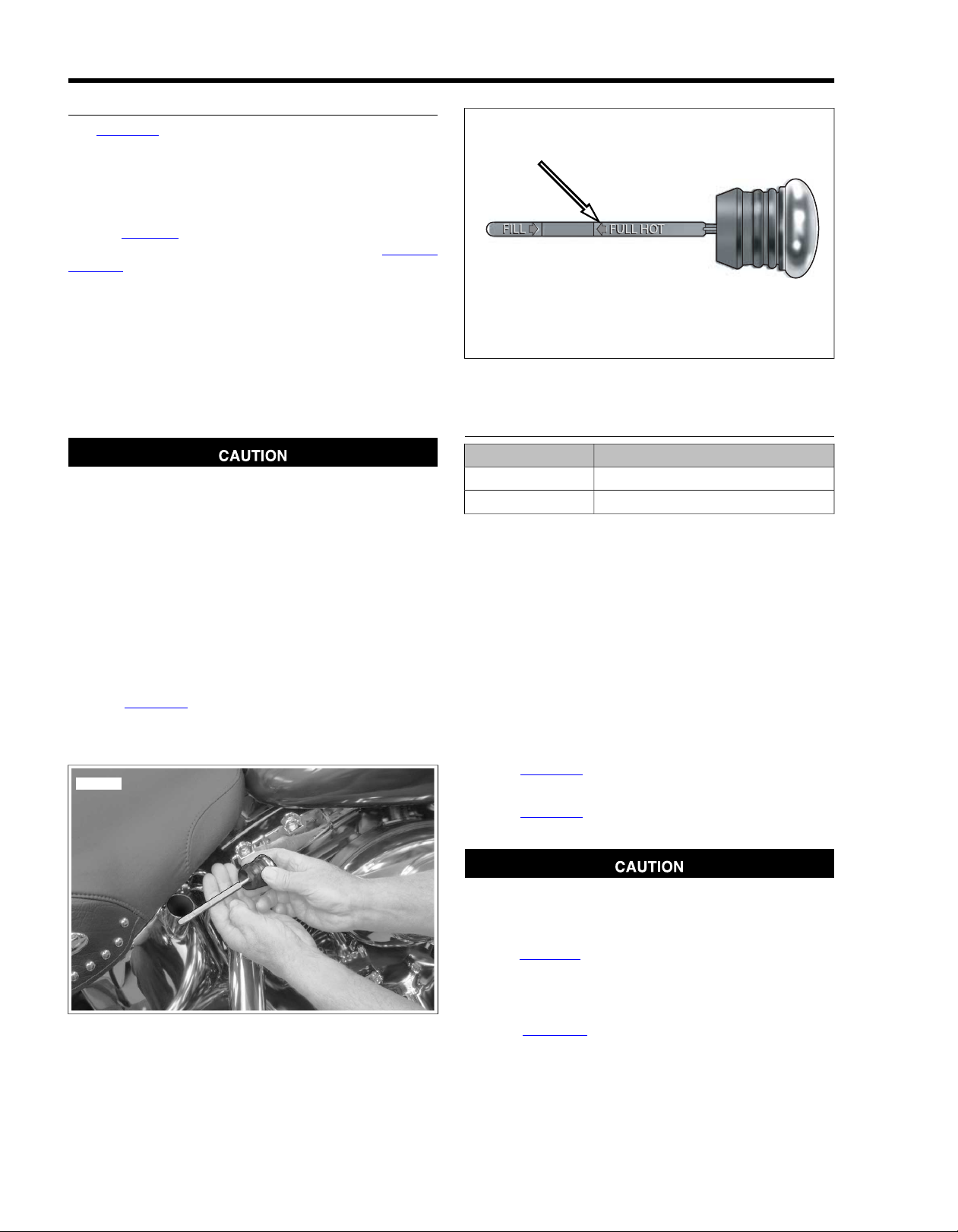
CHECKING AND ADDING OIL
sm03037
sm03039
See Figure 1-1. Checking engine oil level:
• As part of the pre-ride inspection.
• At every scheduled service interval.
Type of Oil
Refer to Table 1-5. Use the proper grade of oil for the lowest
temperature expected before the ne xt oil change. See 1.3 FUEL
AND OIL for specific information regarding winter needs.
If it is necessary to add oil and Harley-Davidson oil is not
available, use an oil certified for diesel engines. Acceptable
diesel engine oil designations include CF-4, CG-4, CH-4, and
CI-4. The preferred viscosities for the diesel engine oils, in
descending order, are 20W-50, 15W-40 and 10W-40. At the
first opportunity, see a Harley-Da vidson dealer to change back
to 100 percent Harley-Davidson oil.
1.5ENGINE OIL AND FILTER
Figure 1-2. Oil Tank Dipstick Upper Groove
Checking Oil Level
Oil level cannot be accurately measured on a cold engine.
For pre-ride inspection, with motorcycle leaning on jiffy
stand on level ground, oil should register on dipstick
between arrows when engine is cold. Do not add oil to
bring the level to the FULL mark on a COLD engine.
(00185a)
Ride motorcycle until engine is warmed up to operating temperature, then do the following.
1. Idle motorcycle on jiffy stand for 1-2 minutes.
2. Shut motorcycle off and leave motorcycle resting on jiffy
stand.
3. See Figure 1-2. Check oil level on dipstick. If necessary,
add oil until oil registers at upper groove on dipstick. Do
not overfill oil tank.
CHANGING OIL AND FILTER
TOOL NAMEPART NUMBER
OIL FILTER WRENCHHD-42311
OIL FILTER WRENCHHD-44067
NOTES
• If the motorcycle is ridden hard, under dusty conditions,
or in cold weather, the oil and filter should be changed
more often.
• All Softail models are shipped from the factory with SAE
20W50 Harley-Davidson 360 Motor Oil.
• All Softail models come equipped from the factory with a
premium 5 micron synthetic media oil filter, Part No.
63798-99 (Chrome) or 63731-99 (Black). These are the
only recommended replacement filters.
1. Ride motorcycle until engine is warmed up to normal
operating temperature.
2. See Figure 1-1. Remove the engine oil filler plug/dipstick
by pulling steadily while moving plug back and forth.
3. See Figure 1-3. Remove the engine oil drain plug with oring (2). Allow oil to drain into a suitable container.
Figure 1-1. Checking Oil Tank Level
1-12 2008 Softail Service: Maintenance
Use Harley-Davidson oil filter wrench for filter removal.
This tool can prevent damage to crankshaft position
sensor and/or sensor cable. (00192b)
4. See Figure 1-4. Remo ve the oil filter using the OIL FILTER
WRENCH (Part No. HD-42311) or OIL FILTER
WRENCH (Part No. HD-44067). Clean the oil filter
mounting surface of any old gasket material.
5. See Figure 1-5. Lube the gasket on new oil filter with
engine oil and install new filter. Hand tighten oil filter 1/2
to 3/4 turn after gasket contacts filter mounting surface.
DO NOT use oil filter wrench for oil filter installation.
Page 30

6. See Figure 1-3. Install oil tank drain plug (2).
sm03041
sm01673
sm01414
a. Inspect o-ring for tears or damage. Replace if
required.Wipe any foreign material from plug.
b. Install o-ring and drain plug. Tighten to 14-21 ft-
lbs (19.0-28.5 Nm).
7. Fill oil tank with the correct amount of oil. Use the proper
grade of oil for the lowest temperature expected before
next oil change. Refer to Table 1-5.
a. Use 2.5 quarts (2.4 liters) of engine oil for a wet
capacity refill.
b. Use 3.0 quarts (2.7 liters) for a dry capacity refill.
NOTE
Use wet capacity values for engines that have just had
the oil drained. Use dry capacity values for engines that
have been disassembled, cleaned in solvent and dried.
8. Check engine oil level using cold check procedure.
9. Start engine and carefully check for oil leaks around drain
plug and oil filter.
10. Check engine oil level using hot check procedure.
Figure 1-4. Oil Filter Wrenches
Figure 1-5. Lubricating New Oil Filter Gasket
1. Frame connection for oil tank drain hose
2. Oil tank drain plug and O-ring
Figure 1-3. Oil Tank Drain Plug
2008 Softail Service: Maintenance 1-13
Page 31

FLUID INSPECTION
1
sm02490
1
sm02491
Direct contact of D.O.T. 4 brake fluid with eyes can cause
irritation. Avoid eye contact. In case of eye contact flush
with large amounts of water and get medical attention.
Swallowing large amounts of D.O .T . 4 brake fluid can cause
digestive discomfort. If swallowed, obtain medical attention. Use in well ventilated area. KEEP OUT OF REACH OF
CHILDREN. (00240a)
D.O.T. 4 brake fluid will damage painted and body panel
surfaces it comes in contact with. Alwa ys use caution and
protect surfaces from spills whenever brake work is performed. F ailure to comply can result in cosmetic damage.
(00239b)
1. See Figure 1-6. Chec k level in rear brake master cylinder
reservoir. Level should be 1/4 ± 1/8 in. (6.35 ± 3.18 mm)
below the gasket surface.
1.6BRAKES
1. Fluid level should be 1/8-1/4 in. (3.2-6.4 mm)
below gasket surface
Figure 1-6. Rear Brake Master Cylinder Reservoir
Do not allow dirt or debris to enter the master cylinder
reservoir . Dirt or debris in the reservoir can cause improper
operation and equipment damage. (00205c)
2. See Figure 1-7. Chec k lev el in front brak e master cylinder
reservoir. Level should be 1/4 ± 1/8 in. (6.35 ± 3.18 mm)
below the gasket surface.
3. Install gaskets and covers .Tighten reservoir cover screws
to 6-8 in-lbs (0.7-0.9 Nm).
After repairing the brake system, test brakes at low speed.
If brakes are not operating properly , testing at high speeds
can cause loss of control, which could result in death or
serious injury. (00289a)
4. Front brake hand lever and rear brake foot pedal must
have a firm feel when applied. If not, bleed system using
only D.O.T. 4 BRAKE FLUID. See 1.15 BLEEDING
BRAKES.
1. Fluid level should be 1/8-1/4 in. (3.2-6.4 mm)
below gasket surface
Figure 1-7. Front Brake Master Cylinder Reservoir
REAR BRAKE PEDAL
Pedal Height
The rear brake pedal is nonadjustable. When brake system
components are properly assembled, brake pedal is correctly
adjusted.
Pedal Lubrication
See Figure 1-8. Rear brak e pedal contains greaseless bushings
(4, 5). Replace bushings if worn.
Pedal Pad
If replacing brake pedal pad (8), slide old pad off brake pedal
(7) then slide new pad on pedal.
1-14 2008 Softail Service: Maintenance
Page 32

1
2
3
4
5
6
12
11
10
9
8
7
sm03054
1. Screw @ 12 - 16 ft lbs (16.3-21.7 Nm)
2. Washer
3. O-ring
4. Bushing
5. Bushing
6. O-ring
7. Brake pedal
8. Pad
9. Cotter pin
10. Washer
11. Master cylinder push rod
12. Clevis pin
Figure 1-8. Rear Brake Pedal (typical)
2008 Softail Service: Maintenance 1-15
Page 33

1.7AIR CLEANER AND EXHAUST SYSTEM
REMOVAL
1. See Figure 1-9. Remove screw (1) and air cleaner cover
(2).
2. Remove three T ORX screws (4) and brac ket (5) from filter
element (6).
3. Gently pull both rubber breather hoses (9) from the element. Remove filter element (6) and gasket (7).
4. Replace the filter element if damaged or if filter media
cannot be adequately cleaned.
Do not use gasoline or solvents to clean filter element.
Flammable cleaning agents can cause an intake system
fire, which could result in death or serious injury . (00101a)
5. Gently pull the breather hoses from the breather bolts on
the backplate (8).
Compressed air can pierce the skin and flying debris from
compressed air could cause serious eye injury. Wear
safety glasses when working with compressed air. Never
use your hand to check for air leaks or to determine air
flow rates. (00061a)
6. Clean filter element.
a. Wash the paper/wire mesh air filter element and
breather hoses in lukewarm water with a mild detergent. Do not strike filter element on a hard surface to
dislodge dirt.
b. Allow filter to either air dry or blow it dry, from the
inside, with low pressure air. Do not use air cleaner
filter oil on the Harley-Davidson paper/wire mesh air
filter element.
c. Hold the filter element up to a strong light source. If
light is uniformly visible through the element, it is
sufficiently clean.
7. Inspect seal ring (3) on cover for cracks or tears. Verify
that it seals tightly to backplate. Replace as required.
8. Inspect breather hoses for tears, cuts, holes or other
damage. Replace as necessary.
NOTE
The breather hoses allow crankcase vapors to be directed into
the air filter element. By providing effective recirculation of
crankcase vapor, the hoses serve to eliminate the pollutants
normally discharged from the crankcase. Air cleaner mounting
without installation of the breather hoses, or with breather hoses
that are not air tight, allows crankcase vapors to be v ented into
the atmosphere in violation of legal emissions standards.This
will also negatively affect the engine's breather system as it
will cause the umbrella valve to flutter.
9. Wipe inside of air cleaner cover and backplate with damp
cloth to remove dust.
1-16 2008 Softail Service: Maintenance
Page 34

9
8
7
6
5
4
3
2
10
11
1
9
8
7
6
5
4
3
2
1
sm03096
7.1. GasketScrew
2. 8.Air cleaner cover Backplate
4. 10.T27 TORX screw (3) Air cleaner assembly: oval
6. Filter element
Figure 1-9. Air Cleaner Assembly
9.3. Breather hose (2)Seal ring
11.5. Air cleaner assembly: roundBracket
INSTALLATION
1. See Figure 1-10. Position new gasket on backplate.
2. Oval air cleaner: see Figure 1-11. Insert two breather
hoses into the holes in back of the filter element and place
the element back into position. Attach breather hoses to
breather screws on backplate.
3. Round air cleaner: place filter element back into position
on backplate and then insert two breather hoses into the
holes on front of the filter element. Place breather hoses
on breather screws on backplate.
4. See Figure 1-9. Install air filter element and bracket.
a. Make sure gasket holes are aligned with backplate
holes.
b. Use three TORX screws (4) to secure bracket and
filter element.Tighten to 40-60 in-lbs (4.5-6.8 Nm).
5. Install air filter cover (2).
a. Apply a drop of LOCTITE THREADLOCKER 243
(blue) to threads of air cleaner cover screw (1).
b. Install air cleaner cover using screw .Tighten to 36-60
in-lbs (4.1-6.8 Nm).
2008 Softail Service: Maintenance 1-17
Page 35

sm02454
Figure 1-10. Gasket (Typical)
sm02455
Figure 1-11. Breather Tubes on Backside of Filter: All But
FLSTSB Domestic
EXHAUST SYSTEM LEAK CHECK
Check the exhaust system f or leaks at every scheduled service
interval as follows:
1. Check entire exhaust system for loose or missing
fasteners, broken pipe clamps or brackets, and obvious
signs of leakage (carbon tracks at pipe joints, etc.).
2. Check for loose or broken heat shields . Repair or replace
as necessary.
3. Start engine, cover muffler ends with clean, dry shop
towels and listen for audible signs of exhaust leakage.
4. Correct any leaks detected. See 4.16 EXHAUST SYSTEM:
ALL BUT FLSTF/FLSTN/FLSTSB or 4.17 EXHAUST
SYSTEM: FLSTF/FLSTN/FLSTSB for exhaust system
removal and installation procedures.
1-18 2008 Softail Service: Maintenance
Page 36

1.8TIRES AND WHEELS
TIRES
Match tires, tubes, air valves and caps to the correct wheel
rim. Contact a Harley-Davidson dealer. Mismatching can
result in damage to the tire bead, allow tire slippage on
the rim or cause tire failure, which could result in death
or serious injury. (00023a)
Use only Harley-Davidson approved tires. See a HarleyDavidson dealer . Using non-approved tires can adversely
affect stability, which could result in death or serious
injury. (00024a)
Use inner tubes on laced (wire spoked) wheels. Using
tubeless tires on laced wheels can cause air leaks, which
could result in death or serious injury. (00025a)
Table 1-7.Tire Pressures: 2008 Softail Models
NOTES
• Tubeless tires are used on all Harley-Davidson cast and
disc wheels.
• Tire sizes are molded on the tire sidewall. Inner tube sizes
are printed on the tube.
• New tires should be stored on a horizontal tire rack. Avoid
stacking new tires in a vertical stack. The weight of the
stack compresses the tires and closes down the beads.
Check tire pressure and tread:
• As part of the pre-ride inspection.
• At every scheduled service interval.
1. Inspect each tire for punctures, cuts and breaks.
2. Inspect each tire for wear . Replace tires bef ore they reach
the tread wear indicator bars.
NOTE
Missing indicator wear bars represent less than 1/32 in. (0.8
mm) tread pattern depth remaining.
3. Check for proper front and rear tire pressures when tires
are cold. Compare results against Table 1-7.
TIRE REPLACEMENT
Inspection
Harley-Davidson tires are equipped with wear bars that
run horizontally across the tread.When wear bars become
visible and only 1/32 in. (0.8 mm) tread depth remains,
replace tire immediately. Using a worn tire can adversely
affect stability and handling, which could result in death
or serious injury. Use only Harley-Davidson approved
replacement tires. (00090b)
See Figure 1-12. Arrows on tire sidewalls pinpoint location of
wear bar indicators.
TIRE PRESSURE (COLD)LOADMODEL
REARFRONT
kPaPSIkPaPSI
2483624836solo riderFLST, FLSTC, FLSTN
2764024836rider and passenger
2623824836solo riderFLSTF, FLSTSB
2904224836rider and passenger
2623820730solo riderFXSTC, FXSTB, FXST
2904220730rider and passenger
2623820730solo riderFXCW, FXCWC
2904220730rider and passenger
Tread wear indicator bars will appear on tire tread surfaces
when 1/32 in. (0.8 mm) or less of tire tread remains. See
Figure 1-13. Always replace tires before the tread wear indic-
ator bars appear.
When To Replace Tires
New tires are needed if any of the following conditions exist:
1. Tread wear indicator bars become visible on the tread
surfaces.
2. Tire cords or fabric become visible through cracked sidewalls, snags or deep cuts.
3. A bump, bulge or split in the tire.
4. Puncture, cut or other damage to the tire that cannot be
repaired.
2008 Softail Service: Maintenance 1-19
Page 37

om00846
Figure 1-12.Tire Sidewall Wear Bar Locator
om00845
2. Inspect any time the wheels are removed.
a. Inspect the play of the wheel bearings by finger while
they are in the wheel.
b. Rotate the inner bearing race and check for abnormal
noise.
c. Make sure bearing rotates smoothly.
3. Check wheel bearings and axle spacers for wear and
corrosion. Excessive play or roughness indicates worn
bearings. Replace bearings in sets only. See 2.6 SEALED
WHEEL BEARINGS, Inspection.
WHEEL SPOKES
Spokes that are too tight can draw nipples through the rim
or distort hub flanges. Spokes that are too loose can
continue to loosen when put in service. Either condition
can adversely affect stability and handling, which could
result in death or serious injury. (00286a)
If nipples require more than one full turn to tighten spoke,
remove tire to check that spoke protrusion has not damaged tube. (00526b)
Figure 1-13.Wear Bar Appearance
WHEEL BEARINGS
1. Replace when bearings exceed end play service wear
limit of 0.002 in. (0.051 mm).
4. Raise motorcycle wheel off the ground.
NOTE
Perform the entire procedure for each spoke, one at a time.
5. Mark one of the spokes with a reference mark to the rim.
6. Loosen spoke 1/4 turn.
NOTES
• Use a spoke torque wrench to tighten spokes.
• Do not tighten spoke more than 1/4 turn past reference
mark. If more tension is needed, label spoke and check
after completing rest of wheel.
7. Tighten spoke to reference mark. If torque is less then the
value listed in Table 1-8, continue to tighten spoke until it
reaches the listed torque.
8. Once the entire wheel has been checked, repeat procedure for each labeled spoke.
9. If more than a few spokes w ere loose, true the entire wheel
following procedure under 2.10 TRUING LA CED WHEELS.
Table 1-8. Spoke Nipple Torque Specification
MINIMUM TORQUERIM TYPE
55 in-lbs (6.2 Nm)All
1-20 2008 Softail Service: Maintenance
Page 38

om00114a
3
2
1
om00709
GENERAL
All models have an automatic chain tensioner. For primary
chain service procedures, see 6.3 DRIVE COMPONENTS.
CHANGING PRIMARY CHAINCASE
LUBRICANT
1. Run motorcycle until engine is warmed up to normal
operating temperature.
When draining or adding lubricant, do not allow dirt, debris
or other contaminants to enter the engine. (00198a)
Be sure that no lubricants or fluids get on tires, wheels or
brakes when changing fluid. Traction can be adversely
affected, which could result in loss of control of the
motorcycle and death or serious injury. (00047d)
2. See Figure 1-14. Remove magnetic drain plug at bottom
of primary chaincase. Drain lubricant into suitable container.
NOTE
Dispose of lubricant in accordance with local regulations.
3. Clean drain plug. If plug has accumulated a lot of debris,
inspect the condition of chaincase components.
4. Install new o-ring on drain plug.
5. Install drain plug back into primary chaincase cover.
Tighten plug to 14-21 ft-lbs (19.0-28.5 Nm).
6. See Figure 1-15. Remove five TORX screws with captive
washers (3) to detach clutch inspection cover (2) from
primary chaincase cover.
7. Remove the seal (1).Wipe oil from groove in chaincase
cover and mounting surface.
Do not overfill the primary chaincase with lubricant.
Overfilling can cause rough clutch engagement, incomplete disengagement, clutch drag and/or difficulty in
finding neutral at engine idle. (00199b)
8. Refer to Table 1-9. P our the specified amount of GENUINE
Harley-Davidson FORMULA+ TRANSMISSION AND
PRIMARY CHAINCASE LUBRICANT (P art No. 99851-05
quart) in through the clutch inspection cover opening.
Table 1-9. Primary Chaincase Lubricant Refill Capacity
CAPACITYITEM
32 oz (0.95 L) wetPrimary chaincase lubricant
40 oz (1.18 L) dry
1.9PRIMARY CHAIN
Figure 1-14. Remov al/Installation of Chaincase Drain Plug
1. Seal
2. Clutch inspection cover
3. Screws with captive washer
Figure 1-15. Clutch Cover
9. Install clutch inspection cover and new seal as follows:
a. Thoroughly wipe all lubricant from cover mounting
surface and groove in chaincase.
b. See Figure 1-15. Position new seal (1) in groove in
primary chaincase cover and press each of the nubs
on seal into the groove.The nubs will retain seal in
position.
c. See Figure 1-16. Insert screw (with captive washer)
through clutch inspection cover and carefully thread
it into the top cover screw hole.
d. Start the remaining four screws (with captive
washers).
e. Alternately tighten screws to 84-108 in-lbs (9.5-12.2
Nm) following torque sequence shown in Figure 1-16.
2008 Softail Service: Maintenance 1-21
Page 39

4
5
2
3
1
sm02844
Figure 1-16. Clutch Cover Torque Sequence
1-22 2008 Softail Service: Maintenance
Page 40

CHANGING TRANSMISSION LUBRICANT
sm03075
sm03076
1. See Figure 1-17. Remove transmission filler plug.
2. See Figure 1-18. Remove transmission drain plug and
drain lubricant into a suitable container.
Do not over-tighten filler or drain plug. Doing so could
result in a lubricant leak. (00200b)
3. Install drain plug.
a. Inspect o-ring on drain plug for tears or damage.
Replace as required.Wipe any foreign material from
plug.
b. Install o-ring and drain plug. Tighten to 14-21 ft-
lbs (19.0-28.5 Nm). Do not over-tighten.
1.10TRANSMISSION LUBRICANT
Be sure that no lubricants or fluids get on tires, wheels or
brakes when changing fluid. Traction can be adversely
affected, which could result in loss of control of the
motorcycle and death or serious injury. (00047d)
4. Fill the transmission with 32 oz. (0.95 liter) of HarleyDavidson FORMULA+ TRANSMISSION AND PRIMARY
CHAINCASE LUBRICANT (Part No. 99851-05, quart size).
5. See Figure 1-19. Check lubricant level.
a. Place motorcycle on jiffy stand.
b. Wipe dipstick clean. Place dipstick inside fill hole.
Dipstick should rest on top thread of filler hole.
Remove dipstick and check level.
c. Lubricant level should be at the FULL mark (1) on
dipstick when removed.
6. Install filler plug/dipstick.
a. Check o-ring (3) on dipstick for tears or damage.
Replace as required.Wipe any foreign material from
plug.
b. Install filler plug/dipstick.Tighten to 25-75 in-lbs (2.8-
8.5 Nm).
Figure 1-17.Transmission Lubricant Check/Fill
Figure 1-18.Transmission Drain Plug (Bottom View)
2008 Softail Service: Maintenance 1-23
Page 41

3
1
2
sm03077
1. Full mark
2. Add mark
3. O-ring
Figure 1-19. Filler Plug/Dipstick
1-24 2008 Softail Service: Maintenance
Page 42

ADJUSTMENT
4
3
2
1
sm02219
1
2
sm02220
NOTE
Perform the clutch adjustment with the motorcycle at room
temperature.The clearance at the adjuster screw will increase
as the powertrain temperature increases. If adjuster screw is
adjusted with power train hot, clearance at push rod bearing
could be insufficient with power train cold and clutch slippage
could occur.
1. Position motorcycle on a suitable lift, upright and level.
Point front wheel straight ahead.
2. Remove five T ORX screws with captiv e washers to detach
clutch inspection cover from primary chaincase cover.
3. Remove and discard seal.
4. See Figure 1-20. Add free play to cable.
a. Slide rubber boot (1) off cable adjuster.
b. Holding cable adjuster (2) with 1/2 in. wrench, loosen
jam nut (3) using a 9/16 in. wrench.
c. Turn cable adjuster (2) until there is a large amount
of free play at clutch hand lever.
1.11CLUTCH
1. Rubber boot
2. Cable adjuster
3. Jam nut
4. Cable end
Figure 1-20. Clutch Cable Adjuster
5. See Figure 1-21. Loosen jam nut (1) on clutch adjuster
screw (2). To take up all free play, turn screw inward
(clockwise) until lightly seated. Activ ate the clutch le v er to
verify the balls are seated in the ramps.
6. Back out adjusting screw (counterclockwise) 1/2 to 1 full
turn.Tighten jamnut to 72-120 in-lbs (8.1-13.6 Nm), while
holding adjusting screw with an Allen wrench.
7. Squeeze clutch lever to maxim um limit three times , to set
ball and ramp release mechanism.
8. Check free play.
a. Turn cable adjuster away from jam nut until slack is
eliminated at hand lever.
b. See Figure 1-22. Pull clutch cable ferrule (2) away
from clutch lever bracket (3) to check free play. Turn
cable adjuster as necessary to obtain 1/16-1/8
in. (1.6-3.2 mm) free play between end of cable f errule
and clutch lever bracket.
9. Hold adjuster with 1/2 in. wrench. Using 9/16 in. wrench,
tighten jam nut against cable adjuster. Cover cable
adjuster mechanism with rubber boot.
1. Jam nut
2. Clutch adjuster screw
Figure 1-21. Clutch Adjuster Screw
2008 Softail Service: Maintenance 1-25
Page 43

1
2
3
4
pd00059
1. Clutch cable
4
5
2
3
1
sm02844
2. Cable ferrule
3. Clutch lever bracket
4. 1/16-1/8 in. (1.6-3.2 mm)
Figure 1-22. Clutch Hand Lever
10. Install clutch inspection cover and new seal as follows:
a. Thoroughly wipe all lubricant from cover mounting
surface and groove in chaincase.
b. Position new seal (1) in g roove in primary chaincase
cover and press each of the nubs on seal into the
groove.The nubs will retain seal in position.
c. Insert screw (with captive washer) through clutch
inspection cover and carefully thread it into the top
cover screw hole.
d. Start the remaining four screws (with captive
washers).
e. Alternately tighten screws to 84-108 in-lbs (9.5-12.2
Nm) following torque sequence shown in Figure 1-23.
Figure 1-23. Clutch Cover Torque Sequence
1-26 2008 Softail Service: Maintenance
Page 44

GENERAL
1
2
sm02222
When a drive belt is replaced for any reason other than stone
damage, it is recommended that the transmission and rear
sprockets also be replaced to increase the longevity of the ne w
drive belt. In the case of stone damage, inspect sprockets for
damage and replace as required.
Never bend belt forward into a loop smaller than the drive
sprocket diameter. Never bend belt into a reverse loop.
Over bending can damage belt resulting in premature
failure, which could cause loss of control and death or
serious injury. (00339a)
CLEANING
1.12REAR BELT AND SPROCKETS
Keep dirt, grease, oil, and debris off the belt and sprockets.
Clean the belt with a rag slightly dampened with a light cleaning
agent.
INSPECTION
Sprockets
NOTE
If chrome chips or gouges to rear sprocket are large enough
to be harmful, they will leave a pattern on the belt face.
1. See Figure 1-24. Inspect each tooth (1) of rear sprocket
for:
a. Major tooth damage.
b. Large chrome chips with sharp edges.
c. Gouges caused by hard objects.
d. Excessive loss of chrome plating (see next step).
2. To check if chrome plating has worn off, drag a scribe or
sharp knife point across the bottom of a groove (2)
(between two teeth) with medium pressure.
a. If scribe or knife point slides across groove without
digging in or leaving a visible mark, chrome plating
is still good.
b. If scribe or knife points digs in and leaves a visible
mark, it is cutting the bare aluminum. A knife point
will not penetrate the chrome plating.
3. Replace rear sprocket if major tooth damage or loss of
chrome exists.
1. Tooth
2. Groove
Figure 1-24. Rear Sprocket
Rear Belt
See Figure 1-25. Inspect drive belt for:
• Cuts or unusual wear patterns.
• Outside edge bevelling (8). Some bevelling is common,
but it indicates that sprockets are misaligned.
• Outside ribbed surface for signs of stone puncture (7). If
cracks/damage exists near edge of belt, replace belt
immediately. Damage to center of belt will require belt
replacement eventually, but when cracks extend to edge
of belt, belt failure is imminent.
• Inside (toothed portion) of belt for exposed tensile cords
(normally covered by nylon la yer and polyethylene layer).
This condition will result in belt failure and indicates worn
transmission sprocket teeth. Replace belt and transmission
sprocket.
• Signs of puncture or cracking at the base of the belt teeth.
Replace belt if either condition exists.
• Replace belt if conditions 2, 3, 6 or 7 (on edge of belt)
exist.
NOTE
Condition 1 may develop into 2 or 3 over time. Condition 1 is
not grounds for replacing the belt, but it should be watched
closely before condition 2 develops which will require belt
replacement.
2008 Softail Service: Maintenance 1-27
Page 45

1
3
5
7
2
4
6
8
Stone
Belt cross-section
Sprocket side
of belt
sm01390
Figure 1-25. Drive Belt Wear Patterns
Table 1-10. Drive Belt Wear Analysis
REQUIRED ACTIONCONDITIONPATTERN
OK to run, but monitor condition.Internal tooth cracks (hairline)1
Replace belt.External tooth cracks2
Replace belt.Missing teeth3
OK to run, but monitor condition.Chipping (not serious)4
OK to run, but monitor condition.Fuzzy edge cord5
Replace belt and sprocket.Hook wear6
Replace belt if damage is on the edge.Stone damage7
OK to run, but monitor condition.Bevel wear (outboard edge only)8
Check idler bearings and bracket attachment.Excess edge wear (XR only)9
1-28 2008 Softail Service: Maintenance
Page 46

INSPECTION
10
0
3
6
1
2
4
5
sm02452
2
1
sm01833
TOOL NAMEPART NUMBER
BELT TENSION GAUGEHD-35381-A
NOTE
Do not rely on "feel" for the proper deflection as this typically
results in belts which are under tensioned. Always use BELT
TENSION GAUGE (Part No. HD-35381-A) to determine the
10 lbs (4.5 kg) deflection force. Loose belts will fail due to
"ratcheting" (jumping a tooth) with resultant tensile cord
crimping and breakage.
Check rear belt deflection:
• As part of the pre-ride inspection.
• At every scheduled service interval.
When checking belt deflection:
• Set belt tension at tightest point in belt.
• Perform procedure with motorcycle cold.
NOTE
Customers may purchase belt tension gauge from an authorized Harley-Davidson dealer.
1. See Figure 1-26. Obtain BELT TENSION GAUGE (Part
No. HD-35381-A).
2. To use the belt tension gauge:
a. Slide o-ring (4) toward 0 lbs (0 kg) mark (3).
b. Fit belt cradle (2) against bottom of drive belt half-way
between drive pulleys (point 1 in Figure 1-27.)
c. Press upward on knob (6) until o-ring slides down to
10 lbs (4.5 kg) mark (5).
1.13REAR BELT DEFLECTION
1. Belt tension gauge
2. Belt cradle
3. 0 lbs (0 kg) mark
4. O-ring
5. 10 lbs (4.5 kg) mark
6. Knob
Figure 1-26. Belt Tension Gauge (Part No. HD-35381-B)
3. See Figure 1-27. Check Drive belt deflection. Apply 10
lbs (4.5 kg) of force upward at point 1.
4. See Table 1-11. Compare drive belt deflection with spe-
cifications listed in the table.
Table 1-11. Rear Belt Deflection
ALL BUT FLSTN,
9/16-5/8 in.
(14.3-15.9 mm)
11/16-3/4 in.
(17.5-19.1 mm)
With motorcycle on
jiffy stand without
rider or luggage
V ehicle upright with
rear wheel in air
FLSTN, FXCW/CVEHICLE
1/4-5/16 in.
(6.4-7.9 mm)
5/16-3/8 in.
(7.9-9.5 mm)
FXCW/C
1. 10 lbs (4.5 kg) of force
2. Amount of deflection
Figure 1-27. Checking Belt Deflection
ADJUSTMENT
If belt adjustment is necessary, perf orm the following procedure:
NOTE
The axle nut retainer used on FXCW/C models will remain in
the axle nut and does not need to be removed.
1. All but FXCW/C: See Figure 1-28. Remove e-clip (1).
Loosen rear axle nut (2).
2. FXCW/C: See Figure 1-29. Loosen rear axle nut (2).
3. Adjust belt tension by turning the axle adjusters (3) an
equal number of turns to keep the wheel aligned until the
specification in Table 1-11 is achieved.
2008 Softail Service: Maintenance 1-29
Page 47

4. Tighten axle nut (2) to 95-105 ft-lbs (128.8-142.4 Nm).
1
2
3
sm02594
1
3
2
smo3882
5. All but FXCW/C: install e-clip.
6. Verify rear wheel alignment. See 2.12 VEHICLE ALIGN-
MENT.
Check wheel bearing end play after tightening axle nut to
specified torque. Excessive end play can ad versel y affect
stability and handling. Insufficient end play can cause
bearing seizure. Either condition can cause loss of control,
which could result in death or serious injury. (00285a)
7. Check wheel bearing end play. See 2.6 SEALED WHEEL
BEARINGS, Inspection.
1. Retainer
2. Axle nut
3. Axle adjuster
Figure 1-29. Axle Adjusters: FXCW/C
1. E-Clip
2. Axle nut
3. Axle adjuster
Figure 1-28. Axle Adjusters: All But FXCW/C
1-30 2008 Softail Service: Maintenance
Page 48

1.14THROTTLE CABLES
2
1
4
3
sm02225
2
5
1
6
4
3
sm02226
CABLE INSPECTION, LUBRICATION AND
ADJUSTMENT
Inspection and Lubrication
1. See Figure 1-30. Remove two screws (1) to separate the
upper handlebar housing from the lower housing.
2. Unhook each ferrule and cable from the throttle grip and
remove the throttle sleeve.
3. Apply a light coat of graphite to the handlebar and replace
throttle grip.
4. Put one or two drops of SUPER OIL (Part No. HD-9496885TV) into the housing of each cable.
5. When assembling the handlebar housing, tighten both
screws (1) to 35-45 in-lbs (4.0-5.1 Nm).
Adjustment
The throttle control must operate freely without binding. With
the throttle friction adjustment screw backed off, the throttle
grip must freely return to the closed (idle) position.The throttle
control also must open and close freely when the front wheel
is turned to both the right and left fork stops. If the throttle grip
does not return to the idle position freely, check the throttle
friction adjustment screw tension. If the adjuster screw is
backed off, inspect the cables for short bends.
tighten the jam nut against the cable adjuster . Cover cable
adjuster mechanism with rubber boot.
6. Turn the front wheel full right.Turn the idle cable adjuster
counterclockwise until the cable housing (4) just touches
the spring (6) in the cable guide (as seen through slot).
7. Work the throttle grip to verify that the throttle cable returns
to the idle position when released. If the cable does not
return to idle, turn the cable adjuster clockwise slightly
until the correct response is achieved.
8. Tighten jam nut against the cable adjuster and cover cab le
adjuster mechanism with rubber boot.
1. Screw (2)
Before starting engine, be sure throttle control will snap
back to idle position when released. A thr ottle control that
prevents engine from automatically returning to idle can
lead to loss of control, which could result in death or serious injury. (00390a)
Do not tighten throttle friction adjustment screw to the
point where the engine will not return to idle automatically .
Over-tightening can lead to loss of vehicle control, which
could result in death or serious injury. (00031b)
Adjust throttle cables:
1. See Figure 1-30. Slide rubber boot off throttle cable
adjuster mechanism (2).
2. Holding cable adjuster with a 3/8 inch wrench, loosen jam
nut turning in a clockwise direction.
3. Back jam nut (3) away from cable adjuster until it stops.
Turn cable adjuster clockwise until it contacts jam nut.
Repeat procedure on idle cable adjuster.
4. See Figure 1-31. Point the front wheel straight ahead.
Gently turn the throttle grip so that the throttle is wide open
(fully counterclockwise) and then hold in position. Now
turn the throttle cable adjuster counterclockwise until the
throttle cam (2) just touches the cam stop (5) on the
induction module.
5. Release the throttle grip, turn throttle cable adjuster
counterclockwise an additional 1/2-1 full turn, and then
2. Throttle cable adjuster
3. Jam nut (2)
4. Idle cable adjuster
Figure 1-30.Throttle Cable Adjusters
1. Throttle cable
2. Throttle cam
3. Idle cable
4. Idle cable housing
5. Cam stop
6. Spring
Figure 1-31. Induction Module Cable Connection
2008 Softail Service: Maintenance 1-31
Page 49

1.15BLEEDING BRAKES
sm03914
sm03913
GENERAL
Use denatured alcohol to clean brake system components.
Do not use mineral-based solvents (such as gasoline or
paint thinner), which will deteriorate rubber parts even
after assembly. Deterioration of these components can
cause brake failure, which could result in death or serious
injury. (00291a)
Direct contact of D.O.T. 4 brake fluid with eyes can cause
irritation. Avoid eye contact. In case of eye contact flush
with large amounts of water and get medical attention.
Swallowing large amounts of D.O .T . 4 brake fluid can cause
digestive discomfort. If swallowed, obtain medical attention. Use in well ventilated area. KEEP OUT OF REACH OF
CHILDREN. (00240a)
D.O.T. 4 brake fluid will damage painted and body panel
surfaces it comes in contact with. Alwa ys use caution and
protect surfaces from spills whenever brake work is performed. F ailure to comply can result in cosmetic damage.
(00239b)
tubing. When brake lever/pedal has moved its full range
of travel, close bleeder valve (clockwise). Allow brake
lever/pedal to return slowly to its released position.
Figure 1-32. Front Brake Bleeder Valve (Typical)
Do not allow dirt or debris to enter the master cylinder
reservoir . Dirt or debris in the reservoir can cause improper
operation and equipment damage. (00205c)
Front brake hand lever and rear brake foot pedal must have a
firm feel when brakes are applied. If not, bleed system as
described.
PROCEDURE
NOTE
Hydraulic brake fluid bladder-type pressure equipment can be
used to fill brake master cylinder through the bleeder valve.
Remove master cylinder reservoir cov er so that system cannot
pressurize. Do not use pressure bleeding equipment when the
hydraulic system is sealed with master cylinder reservoir cov er
and gasket in place.
1. Remove bleeder v alv e cap. Install end of a length of clear
plastic tubing over caliper bleeder valve; place other end
in a clean container. Stand motorcycle upright.
a. Front brake bleeder valve-see Figure 1-32.
b. Rear brake bleeder valve-see Figure 1-33.
2. Add D.O.T. 4 BRAKE FLUID to master cylinder reservoir.
Fluid level should be 1/4 ± 1/8 in. (6.35 ± 3.18 mm) below
the gasket surface. Depress and hold brake lever/pedal
to build up hydraulic pressure.
3. Open bleeder valve slowly about 1/2-turn counterclockwise; brake fluid will flow from bleeder valve and through
Figure 1-33. Rear Brake Bleeder Valve
4. Repeat two previous steps until all air bubb les are purged.
5. Tighten bleeder valve to 80-100 in-lbs (9.0-11.3 Nm).
Install bleeder valve cap.
6. Verify master cylinder fluid level as described in previous
step.
After repairing the brake system, test brakes at low speed.
If brakes are not operating properly , testing at high speeds
can cause loss of control, which could result in death or
serious injury. (00289a)
7. Attach covers to master cylinder reservoirs.Tighten screws
on covers to 6-8 in-lbs (0.7-0.9 Nm).
1-32 2008 Softail Service: Maintenance
Page 50

INSPECTION
4
3
2
4
3
2
5
1
sm02217
Check brake pads and discs:
• At every scheduled service interval.
• Whenever the components are removed during service
procedures.
Brake Pads
Direct contact of D.O.T. 4 brake fluid with eyes can cause
irritation. Avoid eye contact. In case of eye contact flush
with large amounts of water and get medical attention.
Swallowing large amounts of D.O .T . 4 brake fluid can cause
digestive discomfort. If swallowed, obtain medical attention. Use in well ventilated area. KEEP OUT OF REACH OF
CHILDREN. (00240a)
D.O.T. 4 brake fluid will damage painted and body panel
surfaces it comes in contact with. Alwa ys use caution and
protect surfaces from spills whenever brake work is performed. F ailure to comply can result in cosmetic damage.
(00239b)
1.16BRAKE PADS AND DISCS
Always replace brake pads in complete sets for correct
and safe brake operation. Improper brake operation could
result in death or serious injury. (00111a)
See Figure 1-34. Replace brake pads (3) if brake pad friction
material on either the front or rear caliper is worn to 0.04
in. (1.02 mm) or less above the backing plate (4). Always
replace both pads in a caliper as a set. See 1.16 BRAKE PADS
AND DISCS, Brake Pad Replacement.
When checking the brake pads and discs, inspect the brake
hoses for correct routing and any signs of damage.
Brake Disc
• The minimum brake disc (2) thickness is stamped on the
• Maximum brake disc lateral runout and warpage is 0.008
Replace disc if badly scored or warped. See 2.3 FRONT
WHEEL: ALL BUT FLSTSB, 2.4 FRONT WHEEL: FLSTSB,
or 2.5 REAR WHEEL.
side of the disc.
in. (0.2 mm) when measured near the outside diameter.
1. Front brake caliper (viewed from below)
2. Brake disc
3. Brake pads
4. Backing plate
5. Rear brake caliper (viewed from above)
Figure 1-34. Brake Pad Inspection
BRAKE PAD REPLACEMENT
Rear Brake Caliper
1. Remove right saddlebag, if present.
2. See Figure 1-35. Loosen, but do not remove, pad pin (2)
(metric).
3. Remove mounting bolt (1) and slider pin (3). Pull rear
caliper with pads away from brake disc.
4. Remove pad pin and pads. Note the pad's original orientation for replacement purposes.
2008 Softail Service: Maintenance 1-33
Page 51

2
3
1
SM03916
1. Mounting bolt
sm04639
1
2
sm04527
2
1
sm04625
2. Pad pin
3. Slider pin
Figure 1-35. Rear Brake Caliper
5. Remove the rear master cylinder reservoir cap.
NOTE
As the pistons are pushed back into the caliper, fluid le v el may
rise above the recommended 1/4 ± 1/8 in. (6.35 ± 3.18 mm)
below the gasket surface. Fluid may have to be removed to
allow for this.
6. Using the old brake pad and a C-clamp, retr act the pistons
fully into the caliper.
7. Place cover over rear master cylinder to help prevent
contamination.
Figure 1-36.Torque Clip
Always replace brake pads in complete sets for correct
and safe brake operation. Improper brake operation could
result in death or serious injury. (00111a)
8. Inspect pad pin for grooving and wear. Measure the pad
pin diameter in an unworn area, and then in the area of
any grooving or wear . If wear is more than 0.015 in. (0.38
mm), replace pin.
9. See Figure 1-36. Inspect torque clip. Replace if worn or
damaged.
10. See Figure 1-37. Inspect anti-rattle spring. Replace if worn
or damaged.
NOTE
When installing brake pads, make sure inner brake pad tabs
(2) mount between caliper and anti-rattle spring tabs (1).
11. See Figure 1-35. Install new brake pads with pad pin (2)
onto caliper using the same orientation as the ones previously removed.Tighten pad pin to 80-120 in-lbs (9.0-13.6
Nm).
12. See Figure 1-38 Install caliper with brake pads on either
side of brake disc. Make sure brak e pad tab (1) is properly
inserted into torque clip (2) for each brake pad.
13. See Figure 1-35. Install mounting bolt (1) and slider pin
(3).Tighten both to 10-14 ft-lbs (13.6-18.9 Nm).
1. Anti-rattle spring tabs
2. Inner brake pad tab
Figure 1-37. Anti-rattle Spring
1. Brake pad tab
2. Torque clip
Figure 1-38. Rear Brake Pad Installation
1-34 2008 Softail Service: Maintenance
Page 52

After servicing brakes and before moving motorcycle,
pump brakes to build brake system pressure. Insufficient
pressure can adversely affect brake performance, which
could result in death or serious injury. (00279a)
14. Pump brake pedal to move pistons out until they contact
both brake pads.Verify piston location against pads.
15. Check brake fluid level in master cylinder. Fill to proper
level if necessary using D.O.T. 4 BRAKE FLUID. Install
master cylinder reservoir cap.Tighten reservoir cap screws
to 6-8 in-lbs (0.7-0.9 Nm).
16. Install right saddlebag if necessary.
After repairing the brake system, test brakes at low speed.
If brakes are not operating properly , testing at high speeds
can cause loss of control, which could result in death or
serious injury. (00289a)
17. Test brake system.
a. Turn ignition switch ON. Pump brake pedal to verify
operation of the brake lamp.
b. Test ride the motorcycle. If the brakes feel spongy,
bleed the system. See 1.15 BLEEDING BRAKES.
NOTE
Avoid making hard stops for the first 100 miles (160 km).This
allows the new pads to become conditioned to the brake discs .
Front Brake Caliper
NOTE
To change the front brake pads on FLSTSB, see 2.15 FR ONT
BRAKE CALIPER: FLSTSB.
1. Remove the front master cylinder reservoir cap. As the
pistons are pushed back into the caliper, fluid level may
rise above the recommended 1/4 ± 1/8 in. (6.35 ± 3.18
mm) below the gasket surface. Fluid may need to be
removed to allow for this.
2. See Figure 1-39. Loosen, but do not remove bridge
bolt/pad pin (3) (metric).
3. Remove both caliper mounting bolts (1, 2) (metric). Detach
caliper from front forks and brake disc.
4. Pry the pads back to force all four caliper pistons into their
bores.
NOTE
The brake pads hav e tabs that are clipped onto the pad springs.
Disengage the tabs from the pad springs as you remove the
pads.
5. With the pistons retracted, remove the bridge bolt/pad pin
and remove brake pads.
6. Inspect bridge bolt/pad pin for grooving and wear . Measure
the pad pin diameter in an unworn area, and then in the
area of any grooving or wear. If wear is more than 0.015
in. (0.38 mm), replace the pin.
Always replace brake pads in complete sets for correct
and safe brake operation. Improper brake operation could
result in death or serious injury. (00111a)
NOTES
• See Figure 1-40. Ensure the pad spring tabs (1) on brak e
pad engage the pad springs in the pistons.
• If the directional tab (2) does not face down when caliper
is installed, brake noise may develop.
7. Install new pads into caliper.The directional tab (2) must
face down when caliper is installed.
8. Loosely install the center bridge bolt/pad pin.
9. Attach caliper to front fork.
a. See Figure 1-39. Place caliper over brake disc with
bleeder valve facing upward.
b. Loosely install long mounting bolt (1) (metric) into
upper hole on fork leg.
c. Install short mounting bolt (2) (metric) into lower hole
on fork leg.Tighten bottom mounting bolt to 28-38 ftlbs (38.0-51.5 Nm).
d. Final tighten the top mounting bolt to 28-38 ft-
lbs (38.0-51.5 Nm).
e. Final tighten center bridge bolt/pad pin (3) to 15-16
ft-lbs (20.3-22.6 Nm).
10. Pump brake hand lever to move pistons out until they
contact both brake pads. Verify piston location against
pads. If the front wheel is off the ground, rotate wheel to
check for excessive brake pad drag.
11. Check brake fluid level in master cylinder. Fill to proper
level if necessary using D.O.T. 4 BRAKE FLUID. Install
master cylinder reservoir cap.Tighten reservoir cap screws
to 6-8 in-lbs (0.7-0.9 Nm).
After repairing the brake system, test brakes at low speed.
If brakes are not operating properly , testing at high speeds
can cause loss of control, which could result in death or
serious injury. (00289a)
12. Test brake system.
a. Turn ignition switch ON. Pump brake hand lever to
verify operation of the brake lamp.
b. Test ride the motorcycle. If the brakes feel spongy,
bleed the system. See 1.15 BLEEDING BRAKES.
NOTE
Avoid making hard stops for the first 100 miles (160 km).This
allows the new pads to become conditioned to the brake discs .
2008 Softail Service: Maintenance 1-35
Page 53

3
1
2
sm04574
1. Long mounting bolt (metric)
1
1
2
sm04031
2. Short mounting bolt (metric)
3. Pad pin (metric)
Figure 1-39. Front Brake Caliper (Left Side Shown)
1. Pad spring tabs
2. Directional tab
Figure 1-40. Front Brake Pad
1-36 2008 Softail Service: Maintenance
Page 54

1.17BATTERY MAINTENANCE
om01163
41
2 3 5
6
sm02241
GENERAL
Batteries contain sulfuric acid, which could cause severe
burns to eyes and skin. Wear a protective face shield,
rubberized gloves and protective clothing when working
with batteries. KEEP BA TTERIES A W A Y FROM CHILDREN.
(00063a)
Never remove warning label attached to top of battery.
Failure to read and understand all precautions contained
in warning, could result in death or serious injury . (00064a)
Batteries, battery posts, terminals and related accessories
contain lead and lead compounds, and other chemicals
known to the State of California to cause cancer , and birth
defects or other reproductive harm. Wash hands after
handling. (00019e)
All AGM batteries are permanently sealed, maintenance-free,
valve-regulated, lead/calcium and sulfuric acid batteries.The
batteries are shipped pre-charged and ready to be put into
service. Do not attempt to open these batteries for an y reason.
NOTE
For charging information, see 1.17 BATTERY MAINTENANCE,
Charging Battery. For testing information, see ELECTRICAL
DIAGNOSTIC MANUAL.
Figure 1-41. Battery Warning Label
4.1. Keep flames awayContents are corrosive
2. 5.Wear safety glasses Read instructions
6.3. Keep away from childrenContents are explosive
Figure 1-42. Battery Warning label
2008 Softail Service: Maintenance 1-37
Page 55

Table 1-12. Antidotes for Battery Acid
T able 1-13.Voltmeter T est For Battery Charge Conditions
TREATMENTCONTACT
Flush with water.External
Internal
Eyes
Drink large quantities of milk or water, f ollowed
by milk of magnesia, vegetable oil or beaten
eggs. Get immediate medical attention.
Flush with water. Get immediate medical
attention.
CLEANING AND INSPECTION
1. Battery top must be clean and dry. Dirt and electrolyte on
top of the battery can cause battery to self-discharge.
Clean battery top with a solution of baking soda (sodium
bicarbonate) and water (5 teaspoons baking soda per
quart or liter of water).When the solution stops bubbling,
rinse off the battery with clean water.
2. Clean cable connectors and battery terminals using a wire
brush or sandpaper. Remove any oxidation.
3. Inspect the battery screws, clamps and cables for
breakage, loose connections and corrosion. Clean clamps.
4. Check the battery posts for melting or damage caused by
overtightening.
5. Inspect the battery for discoloration, raised top or a warped
or distorted case, which might indicate that the battery has
been frozen, overheated or overcharged.
6. Inspect the battery case for cracks or leaks.
VOLTMETER TEST
Batteries contain sulfuric acid, which could cause severe
burns to eyes and skin. Wear a protective face shield,
rubberized gloves and protective clothing when working
with batteries. KEEP BA TTERIES A W A Y FROM CHILDREN.
(00063a)
Never remove warning label attached to top of battery.
Failure to read and understand all precautions contained
in warning, could result in death or serious injury . (00064a)
STATE OF CHARGEVOLTAGE (OCV)
100%12.7 V
75%12.6 V
50%12.3 V
25%12.0 V
0%11.8 V
CHARGING BATTERY
Safety Precautions
Never charge a battery without first reviewing the instructions
for the charger being used. In addition to the manufacturer's
instructions, follow these general safety precautions:
• Always wear eye, face and hand protection.
• Always charge batteries in a well-ventilated area.
• Turn the charger off before connecting the leads to the
battery to avoid dangerous sparks.
• Never try to charge a visibly damaged or frozen battery.
• Connect the charger leads to the battery; red positive (+)
lead to the positive (+) terminal and black negative (-) lead
to the negative (-) terminal. If the battery is still in the
vehicle, connect the negative lead to the chassis g round.
Be sure that the ignition and all electrical accessories are
turned off.
• Make sure that the charger leads to the battery are not
broken, frayed or loose.
• If the battery gets hotter than 110° F (43° C) during
charging, discontinue charger and allow the battery to
cool.
• Always turn the charger off before removing charger leads
from the battery to avoid dangerous sparks.
Using a Battery Charger
Charge the battery if any of the following conditions exist:
• Vehicle lights appear dim.
• Electric starter sounds weak.
• Battery has not been used for an extended period of time.
Voltmeter Test
Refer to Table 1-13. The voltmeter test provides a general
indicator of battery condition. Check the v oltage of the battery
to verify that it is in a 100% fully charged condition. If the open
circuit (disconnected) voltage reading is below 12.6V, charge
the battery and then recheck the voltage after the battery has
set for one to two hours. If the voltage reading is 12.7V or
above, perform a load test. See the ELECTRICAL DIAGNOSTIC MANUAL for the load test procedure.
1-38 2008 Softail Service: Maintenance
Explosive hydrogen gas, whic h escapes during char ging,
could cause death or serious injury. Charge battery in a
well-ventilated area. Keep open flames, electrical sparks
and smoking materials away from battery at all times.
KEEP BATTERIES AWAY FROM CHILDREN. (00065a)
If battery releases an excessive amount of gas during
charging, decrease the charging rate. Overheating can
result in plate distortion, internal shorting, drying out or
damage. (00413b)
Page 56

1. Perf orm a voltmeter test to determine the state of charge.
See the ELECTRICAL DIAGNOSTIC MANUAL. If battery
needs to be charged, proceed to the next step.
Table 1-14. Battery Charging Rates/Times (Approximate)
AMP
HOUR
VOLTAGE
% OF
CHARGE
NOTE
The figures listed in the table assume that the battery is charging at room temperature. If warmer than room temperature,
use a slightly shorter charging time. If colder, use a slightly
longer charging time.
20 AMP CHARGER10 AMP CHARGER6 AMP CHARGER3 AMP CHARGERSTATE OF CHARGEBATTERY
----100%12.719
15 minutes30 minutes50 minutes1.75 hours75%12.6
30 minutes1 hour1.75 hours3.5 hours50%12.3
45 minutes1.5 hours2.5 hours5 hours25%12.0
1 hour2 hours3 hours, 20 minutes6 hours, 40 minutes0%11.8
NOTE
The use of constant current chargers to charge sealed maintenance-free batteries is not recommended. Any overcharge
will cause dry-out and premature battery failure. If a constant
current charger is the only type available, do not exceed the
charge times listed above and do not continue charging the
battery if it gets hot.When charging, never exceed 15 v olts f or
more than 30 minutes.
Unplug or turn OFF battery charger before connecting
charger cables to battery . Connecting cables with charger
ON can cause a spark and battery explosion, which could
result in death or serious injury. (00066a)
Do not reverse the charger connections described in the
following steps or the charging system of the motorcycle
could be damaged. (00214a)
2. Connect red battery charger lead to the positive (+) terminal of the battery.
3. Connect black battery charger lead to the negative (-)
terminal of the battery.
NOTE
If the battery is still in the vehicle, connect the negative lead
to the chassis ground. Be sure that the ignition and all electrical
accessories are turned off.
4. Step away from the battery and turn on the charger. See
the charging instructions in Table 1-14.
Unplug or turn OFF battery charger before disconnecting
charger cables from battery. Disconnecting clamps with
charger ON can cause a spark and battery explosion, which
could result in death or serious injury. (00067a)
5. After the battery is fully charged, disconnect the black
battery charger lead to the negative (-) terminal of the
battery.
6. Disconnect the red battery charger lead to the positive (+)
terminal of the battery.
7. Mark the charging date on the battery.
8. Perf orm either a conductance test or load test to determine
the condition of the battery. See the ELECTRICAL DIAGNOSTIC MANUAL.
9. If charging battery because voltmeter test reading was
below 12.6 V, perform voltmeter test. See the ELECTRICAL DIAGNOSTIC MANUAL.
DISCONNECTION AND REMOVAL
Disconnect negative (-) battery cable first. If positive (+)
cable should contact ground with negative (-) cable connected, the resulting sparks can cause a battery explosion,
which could result in death or serious injury. (00049a)
1. FXCW/C models: lift back of seat and swing toward fuel
tank.
2. All but FXCW/C: remove the seat.
3. FXCWC models: see Figure 1-43. Remove the battery
cover.
4. FLSTSB models: see Figure 1-44. Remo v e thumbscre w
(2) and frame fairing (1).
5. See Figure 1-45. Remove battery negative cable (black)
from battery negative (-) terminal.
6. Remove battery positive cable (red) from battery positive
(+) terminal.
7. Remove battery.
2008 Softail Service: Maintenance 1-39
Page 57

om01176
2
4
1
3
om01267
2
1
om01174
Figure 1-43. Battery Cover (Remov al Slot Shown): FXCWC
Models
1. Frame fairing
2. Thumbscrew
3. Tab
4. Seat spring mounting bracket
Figure 1-44. Frame Fairing: FLSTSB Models
1. Positive (+) terminal
2. Negative (-) terminal
Figure 1-45. Battery: Softail Models
STORAGE
TOOL NAMEPART NUMBER
GLOBAL BATTERY CHARGER99863-01A
Batteries contain sulfuric acid, which could cause severe
burns to eyes and skin. Wear a protective face shield,
rubberized gloves and protective clothing when working
with batteries. KEEP BA TTERIES A W A Y FROM CHILDREN.
(00063a)
Do not allow battery to completely discharge.The electrolyte in a discharged battery will freeze. The more discharged a battery is, the more easily it can freeze and crack
the battery case. (00218a)
If the motorcycle is to be stored with the security system armed,
connect a GLOBAL BATTERY CHARGER (Part No. 9986301A) to maintain battery charge.
If the motorcycle is to be stored with the battery installed, a
GLOBAL BATTERY CHARGER unavailable, and with the
security system not armed, unplug the maxi-fuse.
If the motorcycle will not be operated for sev eral months , such
as during the winter season, remove the battery from the
motorcycle and fully charge.
See Figure 1-46. Self-discharge is a normal condition and
occurs continuously at a rate that depends on the ambient
temperature and the battery's state of charge. Batteries discharge at a faster rate at higher ambient temperatures. To
reduce the self-discharge rate, store battery in a cool (not
freezing), dry place.
Charge the battery every month if stored at temperatures below
60° F (16° C). Charge the battery more frequently if stored in
a warm area above 60° F (16° C).
1-40 2008 Softail Service: Maintenance
Page 58

NOTES
3 6 9 12 15
50%
75%
100%
0
¡
¡
105°
F (40.5° C)
77° F (25° C)
1
2
sm02838
sm03809
• The GLOBAL BA TTER Y CHARGER (Part No. 99863-01A)
may be used to maintain battery charge for extended
periods of time without risk of overcharging or boiling.
• When returning a battery to service after storage, see
ELECTRICAL DIAGNOSTIC MANUAL.
1. Capacity
2. Months of stand
Figure 1-46. Battery Self-Discharge Rate
INSTALLATION AND CONNECTION
Connect positive (+) battery cable first. If positive (+) cable
should contact ground with negative (-) cable connected,
the resulting sparks can cause a battery explosion, which
could result in death or serious injury. (00068a)
6. See Figure 1-50. Install battery. Tighten positive battery
terminal fastener to 60-72 in-lbs (6.8-8.1 Nm).
7. Install negative battery cable (2) at frame ground (1) before
any accessory ground wires.
8. Install negative battery cable (2) at battery. Tighten negative battery terminal fastener to 60-72 in-lbs (6.8-8.1
Nm).
9. FLSTSB models: install the frame fairing and thumbscrew .
10. FXCWC models: install the battery cover.
After installing seat, pull upward on seat to be sure it is
locked in position. While riding, a loose seat can shift
causing loss of control, which could result in death or
serious injury. (00070b)
11. FXCW/C models: lower seat and press down to engage
locating pins.
12. All but FXCW/C: install seat.
1. See Figure 1-47. Position positive battery cable properly
at starter. Cable end must face 35° +/-10° forward from
left side of vehicle.
Be sure rubber boot covers starter solenoid terminal
connected to positive (+) battery cable. An uncovered
terminal can short and cause sparks, which could result
in a battery explosion and death or serious injury . (00463c)
2. Tighten starter nut to 70-90 in-lbs (7.9-10.2 Nm) and cover
with boot.
3. See Figure 1-48. Place battery caddy into position and
install battery caddy clip (1) under front of battery tray (3).
Make sure tabs (2) of battery caddy fit over rear of batter
tray.
4. See Figure 1-49. Install positive battery cable (1) into clip
Figure 1-47. Positive Battery Cable Routing
in caddy. Place an S-shaped bend in the positive battery
cable at the starter end of the cable.This will help properly
position the terminal end for battery installation.
5. Route rear oxygen sensor harness (2) through clip (3).
Connect the cables to the correct battery terminals. Failure
to do so could result in damage to the motorcycle electrical
system. (00215a)
2008 Softail Service: Maintenance 1-41
Page 59

1
2
3
sm03812
1. Clip
1
2
3
sm03814
2
3
1
sm03813
2. Tabs
3. Battery tray
Figure 1-48. Battery Caddy
1. Positive battery cable
2. Rear oxygen sensor harness
3. Clip
Figure 1-49. Battery Caddy Wire Routing
1. Frame ground
2. Negative battery cable
3. Positive battery cable
Figure 1-50. Battery Connections
1-42 2008 Softail Service: Maintenance
Page 60

1.18SUSPENSION ADJUSTMENTS
2
3
1
sm03080
SHOCK ABSORBERS: SOFTAIL MODELS
TOOL NAMEPART NUMBER
SPANNER WRENCH94455-89
Softail models feature rear shock absorbers that can be
adjusted. Rear shoc k spring preload may be varied to suit your
own personal comfort.
NOTE
Rear shocks should be adjusted with the vehicle resting on the
jiffy stand.
Adjustment
1. Loosen jam nut.
Be sure both shock absorbers are adjusted to same preload position. Improper adjustment can adversely affect
stability and handling, which could result in death or serious injury. (00036a)
2. See Figure 1-51. Use a SPANNER WRENCH (Part
No. 94455-89) to turn the spring adjuster plate to the
desired position.
a. Turning the adjuster plates out (toward locknut)
increases the spring preload to carry a heavier load.
b. Turning the adjuster plates in (away from the loc knut)
decreases the spring preload to carry a lighter load.
3. Tighten jam nut.
1. Rear shock canister
2. Jam nut
3. Spring adjuster plate
Figure 1-51. Rear Shock Adjustment
2008 Softail Service: Maintenance 1-43
Page 61

1.19SPARK PLUGS
sm01640
INSPECTION
Disconnecting spark plug cable with engine running can
result in electric shock and death or serious injury.
(00464b)
1. After the engine has cooled to room temperature, disconnect cables from both spark plugs.
2. Remove spark plugs. If a plug has eroded electrodes,
heavy deposits or a cracked insulator, discard it.
3. See Figure 1-52. Compare your observations of the plug
deposits with the descriptions provided below.
a. A wet, black and shiny deposit on plug base, elec-
trodes and ceramic insulator tip indicates an oil fouled
plug. The condition may be caused by one or more
of the following: worn pistons, worn piston rings, worn
valves, worn valve guides, worn valve seals, a weak
battery or a faulty ignition system.
b. A dry, fluffy or sooty black deposit indicates an air-
fuel mixture that is too rich.
c. A light brown, glassy deposit indicates an overheated
plug. This condition may be accompanied by cracks
in the insulator or by erosion of the electrodes and is
caused by an air-fuel mixture that is too lean, a hotrunning engine, valves not seating or improper ignition
timing. The glassy deposit on the spark plug is a
conductor when hot and may cause high-speed misfiring. A plug with eroded electrodes, heavy deposits
or a cracked insulator must be replaced.
d. A plug with a white, yellow, tan or rusty brown
powdery deposit indicates balanced combustion.
Clean off spark plug deposits at regular intervals.
6. Check condition of threads on cylinder head and plug. If
necessary to remove deposits, apply penetrating oil and
clean out with a thread chaser.
7. Apply LOCTITE ANTI-SEIZE to the spark plug threads.
Install and tighten to 12-18 ft-lbs (16.3-24.4 Nm).
8. Connect spark plug cables. Rear cylinder plug cable
attaches to top coil terminal.Verify that cables are securely
connected to coil and spark plugs.
Figure 1-52.Typical Spark Plug Deposits
SPARK PLUG CABLE INSPECTION
Compressed air can pierce the skin and flying debris from
compressed air could cause serious eye injury. Wear
safety glasses when working with compressed air. Never
use your hand to check for air leaks or to determine air
flow rates. (00061a)
4. If the plugs require cleaning between tune-ups, proceed
as follows:
a. Degrease firing end of spark plug using ELECTRICAL
CONT A CT CLEANER. Dry plug with compressed air.
b. Use a thin file to flatten spark plug electrodes. A spark
plug with sharp edges on its electrodes requires 2540% less firing voltage than one with rounded edges.
c. If the plugs cannot be cleaned, replace with new
spark plugs.
5. Check electrode gap with a wire-type feeler gauge. Bend
the outside of the electrode so only a slight drag on the
gauge is felt when passing it between electrodes. Proper
gap measurement is 0.038-0.043 in. (0.97-1.09 mm).
1-44 2008 Softail Service: Maintenance
1. Inspect spark plug cables. Replace cables that are worn
or damaged.
a. Check for cracks or loose terminals.
b. Check for loose fit on ignition coil and spark plugs.
2. Check cable boots/caps for cracks or tears. Replace
boots/caps that are worn or damaged.
3. See Figure 1-53. Check spark plug cable resistance with
an ohmmeter. Compare values from test with Table 1-15.
Replace cables not meeting resistance specifications.
Table 1-15. Spark Plug Cable Resistance Values
LengthDescription
mmIn.
front cable
rear cable
Resistance
Value (Ohms)
4750-12,67548319.00All except FXCW/C:
1625-43501656.50All except FXCW/C:
1813-48331847.25FXCW/C: both cables
Page 62

1
3
2
4
sm02659
1. Ohmmeter positive lead
2. Ohmmeter negative lead
3. Spark plug cable
4. Ohmmeter
Figure 1-53.Testing Resistance
2008 Softail Service: Maintenance 1-45
Page 63

1.20STEERING HEAD BEARINGS: ALL BUT FLSTSB
6
7
1
3
2
4
5
8
9
10
11
12
sm03245
ADJUSTMENT: FLST , FLSTC, FLSTF , FLSTN
Bearing Adjustment (Fall-away)
1. Support motorcycle in an upright position so the front end
is completely suspended and the vehicle is level.
2. Remove all accessory weight, such as a windshield, that
may influence the wa y the front end swings. If clutch cab le
is routed so it pulls the front end one way or the other,
disconnect it.
3. Place a suitable marking material, such as masking tape,
over the fender tip.
4. Install a pointer so the base is stationary on the floor and
the pointer indicates the center of the fender. The front
end should be straight ahead, however the balance point
may be slightly off center.
5. Check steering head bearing tension.
a. Rotate the front end from steering stop to steering
stop three times and then center the front end.
b. Tap the fender on one side until the front end begins
to "fall-awa y" by itself . Label this point on the marking
material.
c. Repeat the previous step in the other direction.
d. Repeat until marks are consistent. If marks vary, use
the average.
e. Measure distance between marks.
8. Distance is less than 1.0 in. (25.4 mm).
a. See Figure 1-54. Loosen the pinch bolt (4).
b. Loosen lower fork stem pinch bolts.
c. Tighten the fork stem bolt (2) slightly.
d. Tighten the upper fork stem pinch bolt to 25-30 ft-
lbs (33.9-40.7 Nm)
e. Tighten the lower fork stem pinch bolts to 30-35 ft-
lbs (40.7-47.5 Nm)
f. Repeat procedure to determine if fall-away is within
specifications.
NOTE
If adjustment seems to have no impact, check to see if fork
tubes are stuck in clamps. If necessary, strike tubes with a
dead blow hammer to free. Retest steering head bearing tension after freeing forks.
6. The distance between the "fall-aw ay" marks must be 1.0-
2.0 in. (25.4-50.8 mm).
a. If the distance is more than 2.0 in. (50.8 mm), pro-
ceed to step 7.
b. If it is less than 1.0 in. (25.4 mm), proceed to step 8.
7. Distance is more than 2.0 in. (50.8 mm).
a. See Figure 1-54. Loosen the upper fork stem pinch
bolt (4).
b. Loosen lower fork stem pinch bolts.
c. Loosen the fork stem bolt (2) slightly.
d. Tighten the upper fork stem pinch bolt to 25-30 ft-
lbs (33.9-40.7 Nm)
e. Tighten the lower fork stem pinch bolts to 30-35 ft-
lbs (40.7-47.5 Nm)
f. Repeat procedure to determine if fall-away is within
specifications.
1. Fork stem cap
2. Fork stem bolt
3. Washer
4. Pinch bolt
5. Upper bracket
6. Upper dust shield
7. Upper bearing
8. Upper bearing race
9. Lower bearing race
10. Lower bearing
11. Lower dust shield
12. Fork stem and bracket
Figure 1-54. Steering Head: FLST, FLSTC, FLSTF, FLSTN
1-46 2008 Softail Service: Maintenance
Page 64

ADJUSTMENT: FXST, FXSTB, FXSTC,
6
1
3
5
2
4
7
8
9
10
11
12
13
sm03246
FXCW/C
Bearing Adjustment (Fall-away)
1. Support motorcycle in an upright position so the front end
is completely suspended and the vehicle is level.
2. Remove all accessory weight, such as a windshield, that
may influence the wa y the front end swings. If clutch cab le
is routed so it pulls the front end one way or the other,
disconnect it.
3. Place a suitable marking material, such as masking tape,
over the fender tip.
4. Install a pointer so the base is stationary on the floor and
the pointer indicates the center of the fender. The front
end should be straight ahead, however the balance point
may be slightly off center.
5. Check steering head bearing tension.
a. Rotate the front end from steering stop to steering
stop three times and then center the front end.
b. Tap the fender on one side until the front end begins
to "fall-awa y" by itself . Label this point on the marking
material.
c. Repeat the previous step in the other direction.
d. Repeat until marks are consistent. If marks vary, use
the average.
e. Measure distance between marks.
8. Distance is less than 1.0 in. (25.4 mm).
a. See Figure 1-55. Loosen the upper f ork stem brack et
pinch bolts (5).
b. Loosen the lower fork stem pinch bolts.
c. Loosen the fork stem nut (2).
d. Tighten the bearing adjustment nut (6) slightly.
e. Tighten the fork stem nut to 70-80 ft-lbs (94.9-108.4
Nm)
f. Tighten upper triple tree bracket pinch bolts to 25-30
ft-lbs (33.9-40.7 Nm).
g. Tighten lower triple tree bracket pinch bolts to 30-35
ft-lbs (40.7-47.5 Nm).
h. Repeat procedure to determine if fall-away is within
specifications.
NOTE
If adjustment seems to have no impact, check to see if fork
tubes are stuck in clamps. If necessary, strike tubes with a
dead blow hammer to free. Retest steering head bearing tension after freeing forks.
6. The distance between the "fall-aw ay" marks must be 1.0-
2.0 in. (25.4-50.8 mm).
a. If the distance is more than 2.0 in. (50.8 mm), pro-
ceed to step 7.
b. If it is less than 1.0 in. (25.4 mm), proceed to step 8.
7. Distance is more than 2.0 in. (50.8 mm).
a. See Figure 1-55. Loosen the upper f ork stem brack et
pinch bolts (5).
b. Loosen the lower fork stem pinch bolts.
c. Loosen the fork stem nut (2).
d. Loosen the bearing adjustment nut (6) slightly.
e. Tighten the fork stem nut to 70-80 ft-lbs (94.9-108.4
Nm)
f. Tighten upper triple tree bracket pinch bolts to 25-30
ft-lbs (33.9-40.7 Nm).
g. Tighten lower triple tree bracket pinch bolts to 30-35
ft-lbs (40.7-47.5 Nm).
h. Repeat procedure to determine if fall-away is within
specifications.
1. Fork stem cap
2. Fork stem nut
3. Lockwasher
4. Upper bracket
5. Pinch bolt
6. Adjusting nut
7. Upper dust shield
8. Upper bearing
9. Upper bearing race
10. Lower bearing race
11. Lower bearing
12. Lower dust shield
13. Fork stem and bracket
Figure 1-55. Steering Head: FXST/FXSTC/FXSTB
2008 Softail Service: Maintenance 1-47
Page 65

LUBRICATION
sm03087
See Figure 1-56. Use SPECIAL PURPOSE GREASE (Part
No. 99857-97) ev ery 10,000 mile (16,000 km) service interval.
Fill grease fitting on steering neck until grease begins to come
out the top and bottom of the steering head.
Figure 1-56. Grease Fitting
1-48 2008 Softail Service: Maintenance
Page 66

1.21STEERING HEAD BEARINGS: FLSTSB
sm03482
GENERAL
Modifying the Springer front end can adversely affect
stability and handling, which could result in death or serious injury. (00299a)
NOTES
• Do not alter the fender brack ets to lower the f ender . Doing
this could allow the front wheel to bind on the fender during
hard stops or big bumps.
• Do not replace the O.E.M. tire with a higher-aspect ratio
tire. Doing this could allow the front wheel to bind on the
fender during hard stops or big bumps.
• Do not replace the O.E.M. tire with a traditional-looking
21 in. front wheel, tire and front fender. In addition to
above, this could adv ersely aff ect the handling char acteristics of this motorcycle.
• Harley-Davidson has designed and manufactured this
special, custom front end according to our very stringent
and well-tested standards. If you modify the Springer front
end in any way that changes our original design, HarleyDavidson cannot and will not assume responsibility.
Only Touring Harley-Davidson Motorcycles are suitable
for sidecar use. Consult a Harley-Davidson dealer. Use of
motorcycles other than Touring models with sidecars
could result in death or serious injury. (00040a)
NOTE
The springer fork was NOT designed f or sidecar use. DO NOT
use the FLSTSB motorcycle, or any springer fork-equipped
vehicle for this purpose.
Lubrication
Use SPECIAL PURPOSE GREASE (Part No. 99857-97) at
every 2500 mi (4000 km). Fill grease fitting on steering neck
until grease begins to come out the top and bottom of the
steering head.
ADJUSTMENT: FLSTSB
TOOL NAMEPART NUMBER
HD-47255
SPRINGER STEERING HEAD
BEARING TOOL
Bearing Adjustment (Fall-away)
leg studs and upper triple clamp to adjust the steering head
bearing.
Figure 1-57. Springer Steering Head Bearing Tool
(HD-47255)
1. Support motorcycle in an upright position so the front end
is completely suspended and the vehicle is level.
2. Remove all accessory weight, such as a windshield, that
may influence the wa y the front end swings. If clutch cab le
is routed so it pulls the front end one way or the other,
disconnect it.
3. See Figure 1-58. Remove the acorn nut with washer (1)
and rubber washer (2).
4. Place a suitable marking material, such as masking tape,
over the fender tip.
5. Install a pointer so the base is stationary on the floor and
the pointer indicates the center of the fender. The front
end should be straight ahead, however the balance point
may be slightly off center.
6. Check steering head bearing tension.
a. Rotate the front end from steering stop to steering
stop three times and then center the front end.
b. Tap the fender on one side until the front end begins
to "fall-awa y" by itself . Label this point on the marking
material.
c. Repeat the previous step in the other direction.
d. Repeat until marks are consistent. If marks vary, use
the average.
e. Measure distance between marks.
7. The distance between the "fall-aw ay" marks must be 1.0-
2.0 in. (25.4-50.8 mm).
a. If the distance is more than 2.0 in. (50.8 mm), pro-
ceed to step 8.
b. If it is less than 1.0 in. (25.4 mm), proceed to step 9.
Do not use tool to seat upper bearing retainer nut. High
torque will bend pins in the tool. (00527b)
This tool can be used to adjust the steering head bearings by
removing only the acorn nut and rubber washer.Without the
tool, you will have to remove the handlebars, risers, rigid fork
2008 Softail Service: Maintenance 1-49
Page 67

8. Distance is more than 2.0 in. (50.8 mm).
1
2
3
4
sm03446
a. Loosen the upper fork stem pinch bolt (3).
b. See Figure 1-57. Insert the SPRINGER STEERING
HEAD BEARING T OOL (P art No. HD-47255) into the
upper triple clamp and hex bearing retainer holes.
c. See Figure 1-58. Loosen the hex bearing retainer (4)
slightly.
d. Tighten the upper fork stem pinch bolt to 25-30 ft-
lbs (33.9-40.7 Nm)
e. Repeat procedure to determine if fall-away is within
specifications.
9. Distance is less than 1.0 in. (25.4 mm).
a. Loosen the pinch bolt (3).
b. See Figure 1-57. Insert the SPRINGER STEERING
HEAD BEARING T OOL (P art No. HD-47255) into the
upper triple clamp and hex bearing retainer holes.
c. See Figure 1-58.Tighten the hex bearing retainer (4)
slightly.
d. Tighten the upper fork stem pinch bolt to 25-30 ft-
lbs (33.9-40.7 Nm)
e. Repeat procedure to determine if fall-away is within
specifications.
1. Acorn nut with washer
2. Rubber washer
3. Pinch bolt
4. Hex bearing retainer
Figure 1-58. Fork Adjustment
1-50 2008 Softail Service: Maintenance
Page 68

INSPECTION
sm05281
1
9
10
2
3
4
5
11
6
7
11
8
sm05286
NOTE
To perform this adjustment, the spring fork must be secured
to the rigid fork. Use cab le ties to tie wrap the fork legs in place
as shown in Figure 1-59.The spring fork can be disconnected
from the rockers without removing the front end from the
motorcycle.
1. Remove front brake caliper and brake line. See
2.15 FRONT BRAKE CALIPER: FLSTSB.
2. Remove front wheel. See 2.4 FRONT WHEEL: FLSTSB.
Use cable straps to secure spring fork legs to rigid fork
legs. If spring fork legs are not held in place, spring pressure could snap them forward, resulting in death or serious
injury. (00305b)
3. See Figure 1-59. Use cable ties to secure the spring fork
legs to the rigid fork legs.
4. See Figure 1-60. Loosen, but do not remove, the bearing
retainer jam nut (7) and bearing retainer (6) on each
rocker.
5. Remove acorn nut (1) and washer (2) from each spring
fork to rocker pivot stud (thick head) (5). Do not remove
the pivot stud from the rocker at this time.
6. Tighten bearing retainers (6) to 25-35 in-lbs (2.8-4.0 Nm).
7. Hold the bearing retainer in place with a hex driver while
tightening jam nut (7) to 95-105 ft-lbs (128.8-142.4 Nm).
8. Remove the pivot studs (5) from the spring fork (8).
1.22ROCKER BEARINGS: FLSTSB
1. Nut (2)
2. Washer (2)
3. Spherical bearing, fork to rocker
4. Pivot stud, rigid fork to rocker
5. Pivot stud, spring fork to rocker (thick head)
6. Bearing retainer, rigid fork
7. Bearing retainer jam nut
8. Spring fork leg
9. Rigid fork leg
10. Spherical bearing ball, fork to rocker (2)
11. Spherical bearing race, fork to rocker
Figure 1-60. Fork Rocker
9. See Figure 1-61. Using a dial or beam type torque wrench,
rotate the rigid fork pivot stud and rocker through the arc
shown. The torque reading should be 25-35 in-lbs (2.8-
4.0 Nm).
10. If the torque reading in the previous step is out of specification, adjust the bearing retainer to obtain a 25-35 in-
lbs (2.8-4.0 Nm) reading.
NOTE
Figure 1-59. Nylon Ties on Fork Legs
If you feel metal to metal contact (grinding while moving the
rocker), replace the spherical bearings.
11. See Figure 1-60. Attach the spring fork legs (8) to the
rockers by installing the pivot studs (5) (thick head), from
the outboard side, with washers (2) and nuts (1).Tighten
nuts to 45-50 ft-lbs (61.0-67.8 Nm).
12. Install front wheel. See 2.4 FRONT WHEEL: FLSTSB.
13. Install front brake caliper and brake line. See 2.15 FR ONT
BRAKE CALIPER: FLSTSB.
2008 Softail Service: Maintenance 1-51
Page 69

sm05343
Figure 1-61. Rocker Rotation
1-52 2008 Softail Service: Maintenance
Page 70

1.23FRONT FORK OIL
sm03093
sm03921
REPLACING FORK OIL
1. Support the motorcycle so the front end is off the floor and
the forks are fully extended.
Wear safety glasses or goggles when servicing fork
assembly . Do not remove slider tube caps without relieving
spring preload or caps and springs can fly out, which could
result in death or serious injury. (00297a)
NOTE
The FLST, FLSTC, and FLSTF models have a preloaded fork
spring.
2. See Figure 1-62. Remove the fork tube caps.
3. Drain fork oil.
a. FXCW/C models require the fork tubes be removed.
Remove the forks and drain the fork oil. See
2.19 FRONT FORK:TELESCOPIC.
b. All models except FXCW/C, see Figure 1-63. Remov e
and discard the drain screws and washers from each
fork and drain the fork oil.
4. Install new drain screws and washers.
a. FXCW/C models, apply LOCTITE THREADLOCKER
243 (blue) to drain screws and tighten to 12-18 in-
lbs (1.4-2.0 Nm).
b. All models but FXCW/C, tighten drain scre ws to 52-78
in-lbs (5.9-8.9 Nm).
5. Refer to Table 1-16. Fill the fork with Harley-Davidson
TYPE E FORK OIL (Part No. HD-99884-80).
6. Tighten fork tube caps to 40-60 ft-lbs (54.2-81.3 Nm).
Table 1-16.Type E Fork Oil Amounts
MMINCCOZMODEL
112.04.4139513.4FLST, FLSTC,
FLSTN
128.05.0439713.4FLSTF
170.06.6937012.5FXST, FXSTB,
FXSTC
122.04.8072524.5FXCW/C
NOTE
Refer to Table 1-16. Fork oil amounts can be measured two
ways.
• Use oz./cc measurement if fork is left in frame.
• Use in./mm measurement if fork is disassembled. In this
case, oil level is measured from top of fork tube, with
spring removed and fork fully compressed.
Figure 1-63. Fork Drain Screw: All Models Except FXCW/C
(Left Side Shown)
Figure 1-62. Fork Tube Cap
2008 Softail Service: Maintenance 1-53
Page 71

1.24CABLE AND CHASSIS LUBRICATION
GENERAL
Inspect and lubricate the following at scheduled service intervals as specified in 1.2 MAINTENANCE SCHEDULE.
• Front brake hand lever
• Clutch hand lever
• Throttle control cables
• Throttle control grip sleeve
• Clutch cable
• Foot shift lever pivot (if applicable)
• Rear brake lever pivot
• Steering head bearings
• Jiffy stand
If service is on muddy or dusty roads, clean and lubricate at
shorter intervals.
CABLES AND HAND LEVERS
For throttle cables, see 1.14 THROTTLE CABLES.
Use SUPER OIL (Part No. HD-94968-85TV) for hand levers
and cables.
JIFFY STAND
Clean and lubricate the jiffy stand. For more information, see
2.39 JIFFY STAND.
STEERING HEAD BEARINGS
Lubricate the steering head bearings with HARLEY -DA VIDSON
SPECIAL PURPOSE GREASE. See 1.20 STEERING HEAD
BEARINGS: ALL BUT FLSTSB or 1.21 STEERING HEAD
BEARINGS: FLSTSB for procedure.
1-54 2008 Softail Service: Maintenance
Page 72

is03040
1 2 1
om00125
sm02228
INSPECTION
The automatic-on headlamp feature provides increased
visibility of the rider to other motorists. Be sure headlamp
is on at all times. P oor visibility of rider to other motorists
can result in death or serious injury. (00030b)
Check headlamp for proper height and lateral alignment:
• When the new owner takes delivery of the motorcycle.
• When there is a change in load (adding luggage, etc.)
1. Verify correct front and rear tire pressure. See 1.8 TIRES
AND WHEELS.
2. Place motorcycle on level floor (or pavement) in an area
with minimum light.
3. Position motorcycle 25 ft (7.6 m) away from a screen or
wall. Measure the distance from directly below the front
axle to the base of the screen/wall.
4. Set mark for alignment purposes.
a. See Figure 1-64. For FXST, FXSTB, FXCW/C,
FXSTC, and FLSTSB (and HDI FLST/FLSTC/FLSTF)
vehicles, draw a horizontal line 35.0 in. (0.9 m) abo ve
floor on screen/wall.
b. See Figure 1-65. For FLSTC, FLSTF and FLSTN
vehicles, draw a horizontal line level with the center
of the headlamp.
5. Load vehicle with rider, passenger (if normally present)
and any cargo.Weight will compress vehicle suspension
slightly.
6. Stand motorcycle upright with both tires resting on floor
and with front wheel held in straight alignment (directly
forward).
7. See Figure 1-66. Turn ignition switch ON. Set handlebar
headlamp switch to HIGH beam position.
8. Check light beam for alignment.
a. The main beam, which is a broad, flat pattern of light,
should be centered equally above and below the
horizontal line.
b. The main beam of light should also be directed
straight ahead. Properly adjusted headlamps project
an equal area of light to right and left of center.
c. Adjust headlamp alignment if necessary.
1.25HEADLAMP ALIGNMENT
Figure 1-64. Headlamp Alignment
1. Level with center of headlamp
2. 25 feet (7.6 meters)
Figure 1-65. Headlamp Alignment: FLSTC/FLSTF/FLSTN
Domestic Models
Figure 1-66. Headlamp Switch High Beam Setting
2008 Softail Service: Maintenance 1-55
Page 73

ADJUSTMENT
1
2
sm03101
1. See Figure 1-67. Loosen horizontal adjusting bolt (2) to
adjust headlamp beam side to side.
2. Tighten horizontal adjusting bolt (2) to 30-35 ft-lbs (40.7-
47.5 Nm).
3. Loosen vertical adjusting bolt (1) to adjust headlamp up
or down.
4. Tighten vertical adjusting bolt (1) to:
a. All but FXSTC, FXCW/C, and FLSTSB: 35-45 ft-
lbs (47.5-61.0 Nm).
b. FXSTC, FXCW/C:25-30 ft-lbs (33.9-40.7 Nm).
c. FLSTSB: 25-35 ft-lbs (33.9-47.5 Nm).
1. Vertical adjusting bolt
2. Horizontal adjusting bolt
Figure 1-67. Headlamp Adjustment:Typical
1-56 2008 Softail Service: Maintenance
Page 74

1.26CRITICAL FASTENERS
INSPECTION
Inspect critical fasteners, except head bolts at the scheduled
service intervals.
Table 1-17. Critical Fasteners
Notes:
* See 2.36 REAR FENDER: FXCW/FXCWC, Installation for proper torque sequence of upper
and lower mounting bolts.
Refer to Table 1-17.Tighten all critical fasteners, except head
bolts, to service manual specifications. Replace an y damaged
or missing hardware.
TORQUEFASTENERSYSTEM
3.9-5.1 Nm35-45 in-lbsUpper and lower switch housing screwsHand controls
6.8-9.0 Nm60-80 in-lbsClutch lever handlebar clamp screws
6.8-9.0 Nm60-80 in-lbsMaster cylinder handlebar clamp screws
28.5-33.9 Nm21-25 ft-lbsBanjo boltsBrakes
38.0-51.5 Nm28-38 ft-lbsFront brake caliper mounting bolts
20.3-22.6 Nm15-16 ft-lbsFront brake bridge bolt/pad pin
13.6-18.9 Nm10-14 ft-lbsRear brake caliper mounting bolts
9.0-13.6 Nm80-120 in-lbsRear brake pad pin
21.7-32.5 Nm16-24 ft-lbsBrake disc screws, front
40.7-61.0 Nm30-45 ft-lbsBrake disc screws, rear
0.7-0.9 Nm6-8 in-lbsReservoir cover screws
40.7-54.2 Nm30-40 ft-lbsRear master cylinder mounting nut
81.42-88.2 Nm60-65 ft-lbsFront axleAxle nuts
128.1-142.4 Nm95-105 ft-lbsRear axle
40.7-47.5 Nm30-35 ft-lbsLower fork pinch bolts: all but FXCW/CFront fork/handlebars
47.5-54.3 Nm35-40 ft-lbsLower fork pinch bolts: FXCW/C
13.6-19.0 Nm10-14 ft-lbsAxle cap fasteners: FXCW/C
33.9-40.7 Nm25-30 ft-lbsUpper bracket pinch bolt: FLSTC, FLSTN, FLSTF
16.3-20.3 Nm12-15 ft-lbsHandlebar clamp mounting screws
40.7-54.2 Nm30-40 ft-lbsLower clamp (riser) bolts
40.7-47.5 Nm30-35 ft-lbsUpper mounting bolts-initial torqueRear Fender: FXCW/FXCWC*
38.0-43.4 Nm28-32 ft-lbsLower mounting bolts
65.1-70.6 Nm48-52 ft-lbsUpper mounting bolts-final torque
2008 Softail Service: Maintenance 1-57
Page 75

INSPECTION
sm03098
1
3
2
2
sm03099
1. See Figure 1-68.Tighten the rear fork pivot nut to 90-110
ft-lbs (122.0-149.1 Nm).
2. See Figure 1-69. Tighten front engine mounting nuts (1)
to 70-80 ft-lbs (94.9-108.5 Nm).
3. Tighten the upper engine mounting to cylinder head bolts
(2) to 35-40 ft-lbs (47.5-54.3 Nm).
4. Tighten the upper engine to frame mounting bolt (3) to 4550 ft-lbs (61.0-67.8 Nm).
5. Inspect all the engine mounting hardware for damage.
1.27ENGINE MOUNTS
1. Front engine mounting nuts
2. Upper engine mounting to cylinder head bolts
3. Upper engine to frame mounting bolt
Figure 1-69. Engine Mounts
Figure 1-68. Pivot Nut
1-58 2008 Softail Service: Maintenance
Page 76

1.28STORAGE
GENERAL
If the motorcycle will not be operated for sev eral months , such
as during the winter season, there are several things which
should be done to protect parts against corrosion, to preserve
the battery and to prevent the buildup of gum and varnish in
the fuel system.
This work should be performed by your local Harley-Davidson
dealer or other qualified technician following Service Manual
procedures.
PLACING IN STORAGE
TOOL NAMEPART NUMBER
STORAGE COVER98716-87A
Do not store motorcycle with gasoline in tank within the
home or garage where open flames, pilot lights, sparks or
electric motors are present. Gasoline is extremely flammable and highly explosive, which could result in death
or serious injury. (00003a)
1. Run motorcycle until engine is at normal operating temperature. Stop the engine then drain the oil tank, install a new
oil filter, and fill oil tank with the proper grade oil. Check
the transmission lubricant level.
Avoid spills. Slowly remove filler cap. Do not fill above
bottom of filler neck insert, leaving air space for fuel
expansion. Secure filler cap after refueling. Gasoline is
extremely flammable and highly explosive, which could
result in death or serious injury. (00028a)
8. Inspect operation of all electrical equipment and switches.
9. Check tire inflation and inspect tires for wear and/or
damage. See 1.8 TIRES AND WHEELS. If the motorcycle
will be stored for an extended period of time, securely
support the motorcycle under the frame so that all weight
is off the tires.
Be sure that brake fluid or other lubricants do not contact
brake pads or discs. Such contact can adversely affect
braking ability , which could cause loss of contr ol, resulting
in death or serious injury. (00290a)
10. Wash painted and chrome-plated surfaces. Apply a light
film of oil to exposed unpainted surfaces.
Unplug or turn OFF battery charger before connecting
charger cables to battery . Connecting cables with charger
ON can cause a spark and battery explosion, which could
result in death or serious injury. (00066a)
Explosive hydrogen gas, whic h escapes during char ging,
could cause death or serious injury. Charge battery in a
well-ventilated area. Keep open flames, electrical sparks
and smoking materials away from battery at all times.
KEEP BATTERIES AWAY FROM CHILDREN. (00065a)
11. Remove battery from vehicle. Charge battery until the
correct voltage is obtained. Charge the battery every other
month if it is stored at temperatures below 60° F (16° C).
Charge battery once a month if it is stored at temperatures
above 60° F (16° C). See 1.17 BATTERY MAINTEN-
ANCE.
Use care when refueling. Pressurized air in fuel tank can
force gasoline to escape through filler tube. Gasoline is
extremely flammable and highly explosive, which could
result in death or serious injury. (00029a)
2. Prepare your fuel system by filling fuel tank and adding a
gasoline stabilizer. Use one of the commercially availab le
gasoline stabilizers following the manufacturer's instructions.
3. Remove the spark plugs, inject a fe w squirts of engine oil
into each cylinder and crank the engine 5-6 revolutions.
Reinstall spark plugs.
4. Inspect rear belt deflection. See 1.13 REAR BELT
DEFLECTION.
5. Inspect rear belt and sprockets. See 1.12 REAR BELT
AND SPROCKETS.
6. Inspect air cleaner filter. See 1.7 AIR CLEANER AND
EXHAUST SYSTEM.
7. Lubricate controls. See 1.24 CABLE AND CHASSIS
LUBRICATION.
Unplug or turn OFF battery charger before disconnecting
charger cables from battery. Disconnecting clamps with
charger ON can cause a spark and battery explosion, which
could result in death or serious injury. (00067a)
12. If the motorcycle is to be covered, use a material that will
breathe, such as STORAGE COVER (Part No. 9871687A) or light canvas. Plastic materials that do not breathe
promote the formation of condensation, which leads to
corrosion.
REMOVAL FROM STORAGE
The clutch failing to disengage can cause loss of control,
which could result in death or serious injury. Prior to
starting after extended periods of storage, place transmission in gear and push vehicle back and forth several times
to assure proper clutch disengagement. (00075a)
1. Charge and install the battery.
2008 Softail Service: Maintenance 1-59
Page 77

2. Remove and inspect the spark plugs. Replace if necessary.
3. Clean the air cleaner element.
4. If fuel tank was drained, fill fuel tank with fresh gasoline.
5. Start the engine and run until it reaches normal operating
temperature.
6. Check engine oil level. Check the transmission lubricant
level. Fill to proper levels with correct fluids, if required.
7. Perf orm all of the checks in the PRE-RIDING CHECKLIST
in the Owner's Manual.
1-60 2008 Softail Service: Maintenance
Page 78

1.29TROUBLESHOOTING
GENERAL
The Troubleshooting section of this manual is a guide to
diagnose problems. Read the appropriate sections of this
manual before performing any w ork. Impr oper repair and/or
maintenance could result in death or serious injury.
(00528b)
The following check list of possib le operating troubles and their
probable causes will be helpful in keeping a motorcycle in good
operating condition. More than one of these conditions may
be causing the trouble and all should be carefully checked.
NOTE
For further troubleshooting information, see the ELECTRICAL
DIAGNOSTIC MANUAL.
ENGINE
Starter Motor Does Not Operate or Does Not
Turn Engine Over
1. Ignition switch not in IGNITION position.
2. Engine run switch in OFF position.
3. Discharged battery, loose or corroded connections
(solenoid chatters).
4. Starter control circuit, relay, or solenoid faulty.
5. Electric starter shaft pinion gear not engaging or overrunning clutch slipping.
6. TSM/TSSM/HFSM Bank Angle Sensor tripped and
ignition/light key switch not cycled OFF then back to
IGNITION.
7. Security system activated.
8. Motorcycle in gear and clutch not pulled in.
9. Jiffy stand down and transmission in gear (HDI models
only)
10. Main fuse not in place
Engine Turns Over But Does Not Start
1. Fuel tank empty.
2. Fouled spark plugs.
3. Discharged battery, loose or brok en battery terminal connections.
4. Engine lubricant too heavy (winter operation).
NOTE
For cold weather starts, always disengage clutch.
5. Spark plug cables in bad condition and shorting, cable
connections loose or cables connected to incorrect cylinders.
6. Loose wire connection at coil, battery, or ECM connector.
7. Ignition timing incorrect due to faulty coil, ECM or sensors.
8. Bank Angle Sensor tripped and ignition switch not cycled
OFF then back to IGNITION.
9. Fuel filter clogged.
10. Sticking or damaged valve(s) or wrong length push rod(s).
11. Plugged fuel injectors.
Starts Hard
1. Spark plugs in bad condition or have improper gap or are
partially fouled.
2. Spark plug cables in poor condition.
3. Battery nearly discharged.
4. Damaged wire or loose wire connection at one of the battery terminals, ignition coil or ECM connector.
5. Water or dirt in fuel system.
6. Intake air leak.
7. Fuel tank vent hose, filler cap vent or v apor valve plugged,
or fuel line closed off, restricting fuel flow.
8. Engine lubricant too heavy (winter operation).
NOTE
For cold weather starts, always disengage clutch.
9. Ignition not functioning properly (possible sensor failure).
10. Faulty ignition coil.
11. Valves sticking.
12. Partially plugged fuel injector(s).
Starts But Runs Irregularly or Misses
1. Spark plugs in poor condition or partially fouled.
2. Spark plug cables in poor condition and shorting or leaking.
3. Spark plug gap too close or too wide.
4. Faulty ignition coil, ECM, or sensor.
5. Battery nearly discharged.
6. Damaged wire or loose connection at battery terminals,
ignition coil or ECM connector.
7. Intermittent short circuit due to damaged wire insulation.
8. Water or dirt in fuel system.
9. Fuel tank vent system plugged.
10. Air leak at intake manifold or air cleaner.
11. Loose or dirty ECM connector.
12. Faulty Sensor(s): Manifold Absolute Pressure (MAP),
Crank Position (CKP) or Oxygen (O2).
13. Incorrect valve timing.
14. Weak or broken valve springs.
15. Damaged intake or exhaust valve.
16. Partially plugged fuel injector(s).
2008 Softail Service: Maintenance 1-61
Page 79

17. Air cleaner EVAP flapper (if equipped) stuck closed or
inoperative.
A Spark Plug Fouls Repeatedly
1. Fuel mixture too rich.
2. Incorrect spark plug for the kind of service.
3. Piston rings badly worn or broken.
4. Valve guides or seals badly worn.
5. Ignition timing advanced due to faulty sensor inputs (MAP,
CKP)/poorly tuned engine.
6. Internal engine problem.
7. Broken frame.
8. Engine counterbalancer out of time or bearing failed.
9. Rear fork pivot shaft fasteners loose.
10. Front engine mounting bolts loose.
Pre-Ignition or Detonation (Knocks or Pings)
1. Fuel octane rating too low.
2. Faulty spark plugs.
3. Incorrect spark plug for the kind of service.
4. Excessive carbon deposit on piston head or in combustion
chamber.
5. Ignition timing advanced due to faulty sensor inputs (MAP
and/or CKP).
6. Ignition timing advanced due to ECM or sensors (CKP,
ET or MAP) defective.
7. Intake manifold vacuum leak.
Overheating
1. Insufficient oil supply or oil not circulating.
2. Insufficient air flow over engine.
3. Heavy carbon deposits.
4. Ignition timing retarded due to defective ECM or faulty
sensor(s): Manif old Absolute Pressure (MAP) and/or Crank
Position (CKP).
5. Leaking valve(s).
6. O-ring damaged or missing from oil pump/crankcase
junction (also results in poor engine performance).
Valve Train Noise
1. Low oil pressure caused by oil feed pump not functioning
properly or oil passages obstructed.
2. Faulty hydraulic lifter(s).
3. Bent push rod(s).
4. Incorrect push rod length.
5. Rocker arm binding on shaft.
6. Valve sticking in guide.
7. Chain tensioning spring or shoe worn.
8. Cam(s), cam gear(s) or cam bushing(s) worn.
9. Cam timing incorrect.
Excessive Vibration
1. Wheels bent or damaged and/or tires worn or damaged.
2. Primary chain badly worn or links tight as a result of
insufficient lubrication or misalignment.
3. Engine to transmission mounting bolts loose.
4. Upper engine mounting bracket loose.
Check Engine Light Illuminates During
Operation
1. Fault detected. See the ELECTRICAL DIAGNOSTIC
MANUAL for more information.
LUBRICATION SYSTEM
Oil Does Not Return To Oil Tank
1. Oil tank empty.
2. Oil pump not functioning.
3. Return oil pump gears damaged.
4. Restricted oil lines or fittings.
5. Restricted oil filter.
6. Oil pump misaligned or in poor condition.
7. O-ring damaged or missing from oil pump/crankcase
junction (also results in poor engine performance).
Engine Uses Too Much Oil Or Smokes
Excessively
1. Oil tank overfilled.
2. Restricted oil return line to oil tank.
3. Restricted breather operation.
4. Restricted oil filter.
5. Oil pump misaligned or in poor condition.
6. Piston rings badly worn or broken.
7. Valve guides or seals worn or damaged.
8. O-ring damaged or missing from oil pump/crankcase
junction (also results in poor engine performance).
9. Plugged crankcase scavenge port.
10. Oil diluted with gasoline.
Engine Leaks Oil From Cases, Push Rods,
Hoses, Etc.
1. Loose parts.
2. Imperfect seal at gaskets, push rod cover, washers, etc.
3. Restricted breather passages or hose to air cleaner.
4. Restricted oil filter.
5. Oil tank overfilled.
6. Lower rocker housing gasket installed incorrectly (upside
down).
7. Restricted oil return line to oil tank.
1-62 2008 Softail Service: Maintenance
Page 80

8. Porosity.
Low Oil Pressure
1. Oil tank underfilled.
2. Faulty low oil pressure switch.
3. Oil pump o-ring damaged or missing.
4. Bypass valve stuck in open position.
5. Ball missing or leaking in cam support plate.
6. Worn oil pump gerotor(s).
7. Restricted feed hose from oil tank.
8. Oil diluted with gasoline.
High Oil Pressure
1. Bypass valve stuck in closed position.
ELECTRICAL SYSTEM
NOTE
For diagnostic information see the ELECTRICAL DIAGNOSTIC
MANUAL.
Alternator Does Not Charge
1. Voltage regulator module not grounded.
2. Engine ground wire loose or broken.
3. Faulty voltage regulator module.
4. Loose or broken wires in charging circuit.
5. Faulty stator and/or rotor.
Alternator Charge Rate Is Below Normal
1. Weak or damaged battery.
2. Loose connections.
3. Faulty voltage regulator module.
4. Faulty stator and/or rotor.
Speedometer Operates Erratically
1. Contaminated vehicle speed sensor (remove sensor and
clean off metal particles).
2. Loose connections.
TRANSMISSION
Shifts Hard
1. Primary chaincase overfilled with lubricant.
2. Clutch not fully disengaging.
3. Transmission lubricant too heavy (winter operation).
4. Shifter return spring (inside transmission) bent or broken.
5. Bent shifter rod.
6. Shifter forks (inside transmission) sprung.
7. Corners worn off shifter clutch dog rings (inside transmission).
Jumps Out Of Gear
1. Shifter rod improperly adjusted.
2. Shifter drum (inside transmission) improperly adjusted or
damaged/worn.
3. Shifter engaging parts (inside transmission) badly worn
and rounded.
4. Shifter forks bent.
5. Damaged gears.
Clutch Slips
1. Clutch controls improperly adjusted.
2. Insufficient clutch spring tension.
3. Worn friction discs.
Clutch Drags Or Does Not Release
1. Lubricant level too high in primary chaincase.
2. Clutch controls improperly adjusted.
3. Primary chain badly misaligned or too tight.
4. Insufficient clutch spring tension.
5. Clutch discs warped.
Clutch Chatters
Friction discs or steel discs worn or warped.
HANDLING
Irregularities
1. Improperly loaded motorcycle. Non-standard equipment
on the front end such as heavy radio receivers, extra
lighting equipment or luggage tends to cause unstable
handling.
2. Damaged tire(s) or improper front-rear tire combination.
3. Irregular or peaked front tire tread wear.
4. Incorrect tire pressure. See 1.8 TIRES AND WHEELS
5. Shock absorber not functioning normally.
6. Loose wheel axle nuts.Tighten to recommended torque
specification.
7. Rear wheel out of alignment with frame and front wheel.
8. Steering head bearings improperly adjusted. Correct
adjustment and replace pitted or worn bearings and races.
9. Loose spokes (laced wheel vehicles only).
10. Tire and wheel unbalanced.
11. Rims and tires out-of-round or eccentric with hub.
12. Rims and tires out-of-true sideways.
13. Rear fork pivot-improper torque.
BRAKES
Brake Does Not Hold Normally
1. Master cylinder reservoir low on fluid, system leaking or
pads worn.
2008 Softail Service: Maintenance 1-63
Page 81

2. Brake system contains air bubbles.
3. Master cylinder or caliper piston seals worn or parts
damaged.
4. Brake pads contaminated with grease or oil.
5. Brake pads badly worn.
6. Brake disc badly worn or warped.
7. Brake drags - insufficient brake pedal or hand lever freeplay, caliper piston worn or damaged, or excessive brake
fluid in reservoir.
8. Brake fades due to heat build up - brake pads dragging
or excessive braking.
9. Brake fluid leak when under pressure.
1-64 2008 Softail Service: Maintenance
Page 82

SUBJECT............................................................................................................................PAGE NO.
2.1 SPECIFICATIONS.....................................................................................................................2-1
2.2 VEHICLE IDENTIFICATION NUMBER (V.I.N.)..........................................................................2-4
2.3 FRONT WHEEL: ALL BUT FLSTSB..........................................................................................2-6
2.4 FRONT WHEEL: FLSTSB.......................................................................................................2-10
2.5 REAR WHEEL.........................................................................................................................2-12
2.6 SEALED WHEEL BEARINGS.................................................................................................2-15
2.7 WHEEL LACING: 16 INCH RIM..............................................................................................2-18
2.8 WHEEL LACING: 17 INCH RIM..............................................................................................2-21
2.9 WHEEL LACING: 21 INCH RIM..............................................................................................2-24
2.10 TRUING LACED WHEELS....................................................................................................2-27
2.11 CHECKING CAST WHEEL RUNOUT...................................................................................2-30
2.12 VEHICLE ALIGNMENT.........................................................................................................2-31
2.13 FRONT BRAKE MASTER CYLINDER..................................................................................2-32
2.14 FRONT BRAKE CALIPER: ALL BUT FLSTSB......................................................................2-36
2.15 FRONT BRAKE CALIPER: FLSTSB.....................................................................................2-41
2.16 REAR BRAKE MASTER CYLINDER....................................................................................2-47
2.17 REAR BRAKE CALIPER.......................................................................................................2-52
2.18 TIRES....................................................................................................................................2-57
2.19 FRONT FORK:TELESCOPIC...............................................................................................2-60
2.20 FRONT FORK: SPRINGER...................................................................................................2-65
2.21 STEERING HEAD.................................................................................................................2-72
2.22 BELT GUARD AND DEBRIS DEFLECTOR...........................................................................2-76
2.23 REAR SHOCK ABSORBERS...............................................................................................2-77
2.24 REAR FORK..........................................................................................................................2-79
2.25 THROTTLE CONTROL.........................................................................................................2-82
2.26 CLUTCH CONTROL.............................................................................................................2-84
2.27 HANDLEBARS: ALL BUT FLSTF/FLSTSB/FXCW/FXCWC.................................................2-86
2.28 HANDLEBARS: FLSTF.........................................................................................................2-88
2.29 HANDLEBARS: FLSTSB.......................................................................................................2-91
2.30 HANDLEBARS: FXCW/FXCWC............................................................................................2-93
2.31 FRONT FENDER: ALL BUT FLSTSB....................................................................................2-97
2.32 FRONT FENDER: FLSTSB...................................................................................................2-98
2.33 REAR FENDER: FLST/FLSTC............................................................................................2-100
2.34 REAR FENDER: FLSTF......................................................................................................2-102
2.35 REAR FENDER: FXST/FXSTB/FXSTC/FLSTSB................................................................2-104
2.36 REAR FENDER: FXCW/FXCWC........................................................................................2-106
2.37 REAR FENDER: FLSTN......................................................................................................2-108
2.38 REAR FENDER WIRE CONDUIT.......................................................................................2-111
2.39 JIFFY STAND......................................................................................................................2-113
2.40 FORK LOCK........................................................................................................................2-115
2.41 SEAT AND STRAP RETENTION NUT................................................................................2-116
2.42 SEAT: FXST/FXSTB............................................................................................................2-117
2.43 SEAT: FXSTC......................................................................................................................2-118
2.44 SEAT: FXCW/FXCWC.........................................................................................................2-119
2.45 SEAT: FLSTN/FLSTF/FLST/FLSTC....................................................................................2-121
2.46 SEAT: FLSTSB....................................................................................................................2-122
2.47 LUGGAGE RACK: FLSTN...................................................................................................2-124
2.48 SADDLEBAGS: FLSTC.......................................................................................................2-125
2.49 WINDSHIELD: FLSTC.........................................................................................................2-126
CHASSIS
Page 83

NOTES
Page 84

SPECIFICATIONS
Chassis Specifications
Table 2-2. Dimensions: 2008 FLST, FLSTC, FLSTF, FLSTN and FLSTSB
*With 180 lb. (81.6 kg) rider on seat
2.1SPECIFICATIONS
Table 2-1. Capacities: 2008 Softail Models
LITERSU.S.ITEM
18.95.0 galFuel tank (total)
3.81.0 galLow fuel warning light on
2.853.0 U.S. qt.Oil tank with filter
0.951.0 U.S. qt.Transmission (approximate)
0.951.0 U.S. qt.Primary chaincase (approximate)
FLSTSBFLSTNFLSTFFLSTCFLSTITEM
MMIN.MMIN.MMIN.MMIN.MMIN.
1638.364.51638.364.51638.364.51638.364.51638.364.5Wheel base
2298.790.52405.494.72395.294.32400.394.52400.394.5Overall length
967.738.1980.438.6995.739.2995.739.2920.036.2Overall width
124.54.9121.94.8129.55.1129.55.1129.55.1Road clearance
1336.752.61125.244.31130.344.51120.144.11178.046.4Overall height
676.326.6622.324.5645.225.4647.725.5647.725.5Saddle height*
Table 2-3. Dimensions: 2008 FXCW, FXCWC, FXSTB, FXSTC and FXST
*With 180 lb. (81.6 kg) rider on seat.
FXSTFXSTCFXSTBFXCWCFXCWITEM
MMIN.MMIN.MMIN.MMIN.MMIN.
1638.364.51638.364.51638.364.51757.769.21757.769.2Wheel base
2400.394.52400.394.52413.095.02413.095.02413.095.0Overall length
919.536.2927.136.5784.930.9891.535.1891.535.1Overall width
129.55.1129.55.1129.55.1129.55.1129.55.1Road clearance
1178.046.41313.251.71137.944.81168.446.01168.446.0Overall height
662.926.1670.626.4640.125.2641.425.25662.924.5Saddle height*
2008 Softail Service: Chassis 2-1
Page 85

from factory
from factory
Table 2-4.Weights: 2008 FLST, FLSTC, FLSTF, FLSTN and FLSTSB
FLSTSBFLSTNFLSTFFLSTCFLSTITEM
KGLB.KGLB.KGLB.KGLB.KGLB.
318700315695315694329725315694Weight as shipped
51711405261160526116052611605261160GVWR
195430195430195430195430195430GAWR front
322710331730331730331730331730GAWR rear
Table 2-5.Weights: 2008 FXCW, FXCWC, FXSTB, FXSTC, and FXST
FXSTFXSTCFXSTBFXCWCFXCWITEM
KGLB.KGLB.KGLB.KGLB.KGLB.
297654305672298656311686300661Weight as shipped
51011255101125510112553311755331175GVWR
188415188415188415188415188415GAWR front
322710322710322710345760345760GAWR rear
NOTES
• Gross vehicle weight rating (GVWR) (maximum allow able
loaded vehicle weight) and corresponding gross axle
weight rating (GAWR) are given on a label located on the
frame steering head.
• For important information regarding tire data and tire
inflation, see 1.8 TIRES AND WHEELS.
Tire Specifications
Match tires, tubes, air valves and caps to the correct wheel
rim. Contact a Harley-Davidson dealer. Mismatching can
result in damage to the tire bead, allow tire slippage on
the rim or cause tire failure, which could result in death
or serious injury. (00023a)
Table 2-6. Fitment - Tubeless Cast Wheels
WHEEL SIZE
AND POSITION
RIM SIZE AND
CONTOUR
Tire sizes are molded on the sidewall. Refer to the tire fitment
tables below. Rim size and contour are cast or stamped into
the exterior surface of the rim.
Example:T21 x 2.15 TLA DOT. "T" indicates that the rim conforms to Tire and Rim Association standards.The "21" is the
normal diameter of the rim in inches, measured at the bead
seat diameter.The "2.15" is the width of the bead seat measured in inches. "TLA" designates the rim contour. "DO T" means
that the rim meets Department of T ransportation Federal Motor
Vehicle Safety Standards.
TIRE SIZERIM VALVE
HOLE DIA.
Dunlop D407F0.35 in.T17 x 3.50 MT17 in. - Front
140/75R17 78V
Dunlop D2050.35 in.T17 x 6.00 MT17 in. - Rear
200/55R17 78V
Dunlop D407F0.35 in.T19 x 2.15 MT19 in. - Front (FXCW/C)
90/90-19 52H
Dunlop D4070.35 in.T18 x 8.00 MT18 in. - Rear (FXCW/C)
240/40R18 79V
2-2 2008 Softail Service: Chassis
Page 86

Table 2-7.Tire Fitment - Tube Type Steel Laced Wheels
WHEEL SIZE
& POSITION
WHEEL SIZE
& POSITION
RIM SIZE &
CONTOUR
Table 2-8.Tire Fitment - Tube Type Chrome Aluminum Profile Laced Wheels
RIM SIZE &
CONTOUR
TUBE
SIZE
TUBE
SIZE
TIRE
SIZE
Dunlop D402FMT90-16T16x3.00D16 in - Front
MT90B16 72H
Dunlop D402MT90-16/MU85-16T16x3.00 D16 in - Rear (FLSTN)
MU85B16 77H
Dunlop D401MT90-16T16x3.00D16 in - Rear (all but FLSTN)
150/80B16 71H
Dunlop D407FMH90x21T21x2.15 TLA21 in - Front
MH90-21 54H
Dunlop D407200/55R17 M/CT17x6.00 MT17 in - Rear (FXST)
200/55R17 78V
TIRE
SIZE
Dunlop D402FMT90-16T16x3.0 MT16 in - Front
MT90B16 72H
Dunlop D402MT90-16/MU85-16T16x3.0 MT16 in - Rear (FLSTN)
MU85B16 77H
Dunlop D401MT90-16T16x3.0 MT16 in - Rear (all but FLSTN)
150/80B16 71H
Dunlop D407FMH90x21T21x2.15 MT21 in - Front
MH90-21 54H
Table 2-9.Tire Pressures: 2008 Softail Models
TIRE PRESSURE (COLD)LOADMODEL
REARFRONT
kPaPSIkPaPSI
2483624836solo riderFLST, FLSTC, FLSTN
2764024836rider and passenger
2623824836solo riderFLSTF, FLSTSB
2904224836rider and passenger
2623820730solo riderFXSTC, FXSTB, FXST
2904220730rider and passenger
2623820730solo riderFXCW, FXCWC
2904220730rider and passenger
2008 Softail Service: Chassis 2-3
Page 87

VEHICLE IDENTIFICATION NUMBER
om00092
1 HD 1 BW 5 1 3 8 Y 111000
1 2 3 4 5 6 7 8 9 10
om00914
See Figure 2-1.The full 17 digit serial or Vehicle Identification
Number (V .I.N.) is stamped on the steering head and on a label
located on the right front frame down tube.
An abbreviated V.I.N. is stamped on the left side crankcase at
the base of the rear cylinder.
NOTE
Always give the full 17 digit Vehicle Identification Number when
ordering parts or making any inquiry about your motorcycle.
2.2VEHICLE IDENTIFICATION NUMBER (V.I.N.)
Figure 2-1.V.I.N. Stamping Location
Figure 2-2.Typical Harley-Davidson V.I.N.: 2008 Softail Models
Table 2-10. Harley-Davidson V.I.N. Breakdown: 2008 Softail Models
POSSIBLE VALUESDESCRIPTIONPOSITION
1=Originally manufactured for sale within the United StatesMarket designation1
5=Originally manufactured for sale outside of the United States
HD=Harley-DavidsonManufacturer2
1=Heavyweight motorcycle (901 cc and larger)Motorcycle type3
See V.I.N. model tableModel4
5=Twin Cam 96B™, 1584 cc air cooled, fuel injected, balancedEngine type5
1=RegularIntroduction date6
2=Mid-year
3=California/regular
4=Cosmetic changes and/or special introductory date
5=California/cosmetic changes and/or special introductory date
6=California/mid-year
Can be 0-9 or XV.I.N. check digit7
8=2008Model year8
2-4 2008 Softail Service: Chassis
Page 88

BX
JA
Table 2-10. Harley-Davidson V.I.N. Breakdown: 2008 Softail Models
POSSIBLE VALUESDESCRIPTIONPOSITION
Y=York, PA U.S.A.Assembly plant9
variesSequential number10
Table 2-11.V.I.N. Model Codes: 2008 Softail Models
MODELCODEMODELCODE
FLSTF ShrineJGFXST Softail® StandardBV
FLSTC ShrineJHFLSTC Heritage Softail® ClassicBW
®
®
JJFLSTF Fat Boy
JKFXSTB Night Train
JLFLSTN Softail® DeluxeJD
JMFLST Heritage Softail® (Brazil only)JE
FXCW Softail Rocker
FXCWC Softail Rocker Custom
FXSTC Softail Custom
FLSTSB Softail® Cross Bones
™
™
™
™
2008 Softail Service: Chassis 2-5
Page 89

2.3FRONT WHEEL: ALL BUT FLSTSB
3
1
2
sm03915
1
2
sm03123
REMOVAL
1. Block motorcycle underneath frame so front wheel is raised
off the ground.
2. Inspect wheel bearing end play and service bearings if
necessary. See 2.6 SEALED WHEEL BEARINGS.
3. See Figure 2-3. Remove brake caliper. Support caliper
using a rubber bungee cord. Be careful not to scratch the
fender paint.
NOTE
Do not operate front brake lever with the front wheel removed
or the caliper piston may be forced out of piston bore.
Reseating the piston requires disassembly of the caliper.
4. Remove axle nut, lockwasher and washer (3).
5. Label wheel spacers for location (left or right) and orienta-
tion (fork side or wheel side).
6. See Figure 2-4. Loosen the slider cap fasteners (2) and
pull the axle (1) free.
7. Remove wheel from forks.
NOTE
On FLST and FLSTC models, the hub cap will come off with
the wheel.
3. To disassemble FLST and FLSTC hub cap , remove snap
ring from hub spacer. Discard snap ring.
1. Long mounting bolt (metric)
2. Short mounting bolt (metric)
3. Axle nut, lockwasher, and washer
Figure 2-3. Front Caliper and Axle Mounting (Left Side)
DISASSEMBLY
Disc Wheel
NOTE
See 2.18 TIRES to service tire or valve stem assembly.
1. See Figure 2-5. Remo v e spacers (2, 6) from left and right
sides.
2. If necessary, remo v e brak e disc (7). On left side of wheel,
remove five screws (8) to detach brake disc. Discard
screws.
Laced Wheel
1. See Figure 2-6. On all models with laced wheels except
FLST and FLSTC, remove spacers (3, 7) from left and
right sides. All FLST and FLSTC models use a spacer
within the hub cap assembly (2) on the right side.
2. If necessary, remo v e brak e disc (8). On left side of wheel,
remove five scre ws (11) to detach left brak e disc. Discard
screws.
1. Axle
2. Slider cap fasteners and washers
Figure 2-4. Front Wheel Mounting
2-6 2008 Softail Service: Chassis
Page 90

1
2
3
4
5
3
6
7
9
10
8
sm3124
1. Axle
2. Right bearing spacer
3. Bearing (2)
4. Sleeve
5. Disc wheel
6. Left bearing spacer
7. Brake disc
8. Screw (5)
9. Washer
10. Axle nut
Figure 2-5. Disc Front Wheel: FLSTF
2008 Softail Service: Chassis 2-7
Page 91

3
2
1
4
5
6
4
7
8
9
10
11
sm03125
1. Axle
2. Hub spacer, hub cap and snap ring (FLST and FLSTC only)
3. Right bearing spacer (all but FLST and FLSTC)
4. Bearing (2)
5. Sleeve
6. Laced wheel
7. Left bearing spacer
8. Brake disc
9. Washer
10. Axle nut
11. Screw (5)
Figure 2-6. Laced Front Wheel: All but FLSTF
CLEANING AND INSPECTION
1. Inspect all parts for damage or excessive wear. If sealed
wheel bearings must be serviced, see 2.6 SEALED
WHEEL BEARINGS.
Always replace brake pads in complete sets for correct
and safe brake operation. Improper brake operation could
result in death or serious injury. (00111a)
2. Inspect brake rotor and pads. See 1.16 BRAKE PADS
AND DISCS.
ASSEMBLY
Be sure that brake fluid or other lubricants do not contact
brake pads or discs. Such contact can adversely affect
braking ability , which could cause loss of contr ol, resulting
in death or serious injury. (00290a)
Disc Wheel
1. Verify that wheel and tire are true. See 2.11 CHECKING
CAST WHEEL RUNOUT.
2. See Figure 2-5. If removed, install brake disc (7). Ver ify
that brake disc is clean. Install five new screws (8) to
attach brake disc. Tighten screws to 16-24 ft-lbs (21.7-
32.5 Nm).
3. Install spacers (2, 6) with largest chamfered end facing
away from wheel.
Laced Wheel
1. If hub and rim were disassembled, see 2.7 WHEEL
LACING: 16 INCH RIM, 2.8 WHEEL LACING: 17 INCH
RIM, or 2.9 WHEEL LACING: 21 INCH RIM.
2. Verify that wheel and tire are true. See 2.10 TRUING
LACED WHEELS.
3. On FLST and FLSTC models, attach hub cap to spacer
with new snap ring.
4. See Figure 2-6. If necessary, install brake disc in its original position. Verify that brake disc is clean. Install five
2-8 2008 Softail Service: Chassis
Page 92

new screws (11) to attach brake disc (8).Tighten screws
to 16-24 ft-lbs (21.7-32.5 Nm).
5. Install hub assembly (2) or spacers (3, 7) with largest
chamfered end facing away from wheel.
INSTALLATION
1. Apply a light coat of LOCTITE ANTI-SEIZE LUBRICANT
to the axle, bearing bores, and bore of inner sleeve.
2. Place wheel into front fork and install axle.Verify that axle
spacers on right and left side are properly installed.
3. See Figure 2-3. Install the w asher and axle nut (3). Insert
screwdriver or steel rod through hole in axle on right side
of vehicle.While holding axle stationary, tighten axle nut
to 60-65 ft-lbs (81.3-88.1 Nm).
NOTE
In next step, mak e sure front and rear gaps between slider cap
and slider is even.
4. See Figure 2-4. Tighten the slider cap nuts to 11-15 ftlbs (14.9-20.3 Nm).
5. See Figure 2-3. Install the brake caliper to the fork leg
using the long mounting bolt (1) (metric) in top hole and
the short mounting bolt (2) (metric) in bottom hole on fork
leg.
6. Tighten fasteners to 28-38 ft-lbs (38.0-51.5 Nm).
Whenever a wheel is installed and before moving the
motorcycle, pump brakes to build brake system pressure.
Insufficient pressure can adversely affect brake performance, which could result in death or serious injury.
(00284a)
7. Pump brake hand lever to move pistons out until they
contact both brake pads. Verify piston location against
pads.
2008 Softail Service: Chassis 2-9
Page 93

2.4FRONT WHEEL: FLSTSB
REMOVAL
1. Block motorcycle underneath frame so front wheel is raised
off the ground.
2. Inspect wheel bearing end play and replace bearings if
necessary. See 2.6 SEALED WHEEL BEARINGS.
3. Remove front brake caliper . Support caliper using a rubber
bungee cord. Be careful not to scratch the fender paint.
See 2.15 FRONT BRAKE CALIPER: FLSTSB.
NOTE
Do not operate front brake lever with the front wheel removed
or the caliper piston may be forced out of piston bore.
Reseating the piston requires disassembly of the caliper.
4. Remove front fender. See 2.32 FRONT FENDER:
FLSTSB.
5. See Figure 2-7. Remove locknut (15) and washer (16).
Discard nut.
6. Place a towel under hub to catch any loose parts which
may fall from hub.
7. Slide axle (1) out of hub and rockers to remov e front wheel.
DISASSEMBLY
NOTE
See 2.18 TIRES to service tire or valve stem assembly.
If necessary, remove brake disc. Label components so they
may be installed in their original locations. On left side of wheel,
remove five screws to detach brake disc.
NOTE
To service rocker bearings, see 1.22 ROCKER BEARINGS:
FLSTSB.
CLEANING AND INSPECTION
1. Inspect all parts for damage or excessive wear. If sealed
wheel bearings must be replaced, see 2.6 SEALED
WHEEL BEARINGS.
Always replace brake pads in complete sets for correct
and safe brake operation. Improper brake operation could
result in death or serious injury. (00111a)
2. Inspect brake rotor and pads.
a. Minimum brake pad thickness: 0.06 in. (1.6 mm) or
less above the backing plate.
b. Minimum brake disc thickness is stamped on the side
of the disc. Replace disc if badly scored.
c. Maximum brake disc lateral runout and warpage is
0.008 in. (0.2 mm).
ASSEMBLY
Be sure that brake fluid or other lubricants do not contact
brake pads or discs. Such contact can adversely affect
braking ability , which could cause loss of contr ol, resulting
in death or serious injury. (00290a)
1. If previously removed, install brake disc in its original
position. Verify that brake disc is clean. Install five new
screws to attach brake disc.Tighten fasteners to 16-24 ftlbs (21.7-32.5 Nm).
2. If bearings were removed, verify that slee ve (8) is installed.
2-10 2008 Softail Service: Chassis
Page 94

10
13
12
11
18
19
17
14
15
16
3
1
2
6
5
4
7
8
9
sm05309
2. 16.9.Right rocker WasherSleeve
10.3. 17.WheelPivot sleeve Pivot sleeve
5. 19.12.Bearing WasherSpacer
13.6. BracketStrut
7. 14.Strut spacer Left rocker
Figure 2-7. Front Wheel: FLSTSB
15.8.1. LocknutRight side bearingAxle
18.11.4. Rubber spacerLeft side bearingWave washer
INSTALLATION
1. See Figure 2-7. Install axle (1).
a. Apply a light coat of LOCTITE ANTI-SEIZE LUB-
RICANT to the right side bearing (8) inside diameter.
b. From right side of wheel, insert axle through right
2. Install washer (16) and new axle locknut (15). Tighten
rocker (2), pivot slee v e (3), w a v e washer (4), bearing
(5), strut (6), strut spacer (7), right side bearing (8),
and sleeve (9).
c. Continue through wheel, left side bearing (11), spacer
(12), bracket (13), washer (19), rubber spacer (18),
pivot sleeve (17), and left rocker (14).
locknut to 60-65 ft-lbs (81.3-88.1 Nm) while holding axle
stationary.
3. Install front fender . See 2.32 FRONT FENDER: FLSTSB.
4. Install front brake caliper. See 2.15 FRONT BRAKE
CALIPER: FLSTSB.
Whenever a wheel is installed and before moving the
motorcycle, pump brakes to build brake system pressure.
Insufficient pressure can adversely affect brake performance, which could result in death or serious injury.
(00284a)
5. Pump brake hand lever to move pistons out until they
contact both brake pads. Verify piston location against
pads.
2008 Softail Service: Chassis 2-11
Page 95

2.5REAR WHEEL
1
2
3
sm02594
1
3
2
smo3882
REMOVAL
1. Block motorcycle underneath frame so weight of motorcycle is off of rear wheel.
2. Remove saddlebags if equipped.
3. Remove belt guard and debris deflector from rear fork.
See 2.22 BELT GUARD AND DEBRIS DEFLECTOR.
4. Inspect wheel bearing end play and service bearings if
necessary. See 2.6 SEALED WHEEL BEARINGS.
5. Label wheel spacers for location (left or right) and orientation (fork side or wheel side).
6. Remove rear brake caliper from caliper mount and support
using an elastic cord or similar. See 2.17 REAR BRAKE
CALIPER.
NOTES
• The axle nut retainer used on FXCW/C models will remain
in the axle nut and does not need to be removed.
• If the axle nut retainer on FXCW/C modes is removed, it
must be replaced.
7. All but FXCW/C: See Figure 2-8. Remove e-clip (1).
Remove rear axle nut (2).
8. FXCW/C: See Figure 2-9. Remove rear axle nut (2).
9. Loosen both axle adjuster screws (3) an equal number of
turns to remove tension from drive belt.
NOTE
Support rear wheel from underneath during removal.
10. Tap axle tow ards right side and remove . Remove spacers
and caliper mounting bracket.
11. Move wheel forward and slip belt off sprocket.
12. Raise motorcycle to allow enough clearance for removal
of rear wheel.
13. Pull wheel with belt sprocket from rear fork.
2. If necessary, remove brake disc and/or rear sprocket.
a. Remove five scre ws (19) to detach rear sprocket (12).
Discard screws.
b. Remove five screws (3) to remove rear brake disc
(7). Discard screws.
1. E-Clip
2. Axle nut
3. Axle adjuster
Figure 2-8. Axle Adjusters: All But FXCW/C
NOTE
Do not operate rear brake pedal with the rear wheel removed
or the caliper piston may be forced out of piston bores.
Reseating the piston requires disassembly of the caliper.
DISASSEMBLY
1. See Figure 2-10. Remo v e spacers (5, 6, 13) from left and
right sides, if not already previously removed.
2-12 2008 Softail Service: Chassis
1. Retainer
2. Axle nut
3. Axle adjuster
Figure 2-9. Axle Adjusters: FXCW/C
Page 96

4
5
6
7
8
9
11
8
12
13
14
15
16
3
19
18
1
2
17
10
sm03165
11.1. Disc wheelAxle (FXCW/C)
2. 12.Washer (FXCW/C) Rear sprocket
13.3. Left bearing spacerScrew (5)
4. 14.Axle (all but FXCW/C) Washer
15.5. Axle nut (FXCW/C)Right bearing spacer, short
6. 16.Right bearing spacer, long Retainer (FXCW/C)
17.7. Axle nut (all but FXCW/C)Rear brake disc
8. 18.Bearing (2) Retainer (all but FXCW/C)
19.9. Screw (5)Sleeve
10. Laced wheel hub and rim
Figure 2-10. Rear Wheel/Hub (typical)
CLEANING AND INSPECTION
1. Inspect all parts for damage or excessive wear.
2. Inspect brake disc and pads. See 1.16 BRAKE PADS AND
DISCS.
3. Inspect rear belt and sprocket. See 1.12 REAR BELT AND
SPROCKETS.
ASSEMBLY
1. See Figure 2-10. If laced wheel (10) was disassembled,
see 2.7 WHEEL LACING: 16 INCH RIM, 2.8 WHEEL
LACING: 17 INCH RIM, or 2.9 WHEEL LACING: 21 INCH
RIM.
2. Using new screws (3), install brake disc (7) if removed.
Tighten screws to 30-45 ft-lbs (40.7-61.0 Nm).
Do not re-use sprocket mounting screws. Re-using
sprocket mounting screws can result in torque loss and
damage to the sprocket and/or belt assembly. (00480b)
3. Using new screws (19), install belt sprocket (12) if
removed.Tighten screws to 55-65 ft-lbs (74.6-88.1 Nm).
2008 Softail Service: Chassis 2-13
Page 97

4. Verify that wheel and tire are true.
a. For laced wheels, see 2.10 TRUING LACED
WHEELS.
b. For cast wheels, see 2.11 CHECKING CAST WHEEL
RUNOUT.
INSTALLATION
1. See Figure 2-10. Apply a light coat of LOCTITE ANTISEIZE LUBRICANT to the axle (1, 4), bearing bores, and
the bore of the inner sleeve (9).
2. Roll wheel into rear fork and slide drive belt over drive
sprocket.
3. Position left bearing spacer (13) between wheel and f ork.
4. From right side, carefully insert axle [with washer (2) for
FXCW/C] through right rear fork, short spacer (5), rear
caliper mounting bracket, long spacer (6) and into bearing
bore.
Continue sliding axle through wheel hub sleeve, left side
spacer and left rear fork.
5. Install washer (14), axle nut (15, 17), and retainer (16, 18)
6. V erify correct axle alignment (see 2.12 VEHICLE ALIGN-
MENT) and check belt deflection (see 1.13 REAR BELT
DEFLECTION).
Check wheel bearing end play after tightening axle nut to
specified torque. Excessive end play can ad versel y affect
stability and handling. Insufficient end play can cause
bearing seizure. Either condition can cause loss of control,
which could result in death or serious injury. (00285a)
7. Tighten axle nut to 95-105 ft-lbs (128.8-142.5 Nm).
8. Install belt guard and debris deflector. See 2.22 BELT
GUARD AND DEBRIS DEFLECTOR.
9. Install brake caliper and pads. See 2.17 REAR BRAKE
CALIPER.
10. Install saddlebags, if equipped.
Whenever a wheel is installed and before moving the
motorcycle, pump brakes to build brake system pressure.
Insufficient pressure can adversely affect brake performance, which could result in death or serious injury.
(00284a)
11. Pump brake pedal to move pistons out until they contact
both brake pads.Verify piston location against pads.
2-14 2008 Softail Service: Chassis
Page 98

2.6SEALED WHEEL BEARINGS
sm02234
3
6
1
2
4
5
sm02235
INSPECTION
1. Block motorcycle underneath frame, so that the wheel is
raised off the ground.
2. Turn the wheel through several rotations.
3. See Figure 2-11. Mount a magnetic base dial indicator to
the brake disc with the dial contact point on the end of the
axle.
4. Move the wheel from side to side to check end play.
a. Bearing passes inspection if the end play is less than
0.002 in. (0.051 mm).
b. Replace the bearings if end play is not within specific-
ation, or if there is drag, rough rotation, abnormal
noise or anything unusual.
assemble using 25 MM COLLET (Part No. HD-44060-10)
(6).
a. Sparingly apply graphite lubricant to threads of forcing
screw (1) to prolong service life and ensure smooth
operation.
b. Install nut (2), washer (3) and Nice bearing (4) on
screw. Insert assembly through hole in bridge (5).
c. Drop ball bearing inside 25 mm collet (6). Fasten
collet and ball bearing to forcing screw.
4. Hold end of forcing screw and turn collet to expand edges
of collet.
5. See Figure 2-14. When expanded collet has gripped
bearing edges, hold end of forcing screw and turn the nut
to remove bearing from wheel.
6. Remove spacer from inside wheel hub.
7. Repeat procedure for opposite side bearing. Discard all
bearings upon removal.
Figure 2-11.Wheel Bearing Inspection (Front Wheel
Shown)
REMOVAL
TOOL NAMEPART NUMBER
25 MM COLLETHD-44060-10
HD-44060A
1. Remove wheel from motorcycle. See 2.3 FRONT WHEEL:
ALL BUT FLSTSB or 2.4 FRONT WHEEL: FLSTSB.
2. If present, remove hub plate from wheel on opposite side
of front brake disc.
See Figure 2-13. Some wheel hubs ma y not provide adequate
support for the puller bridge. In these cases center a used
brake disc over the hub to support the puller bridge while
removing the bearings.
3. See Figure 2-12. Obtain WHEEL BEARING
INSTALLER/REMOVER (Part No. HD-44060A) and
WHEEL BEARING
INSTALLER/REMOVER
NOTE
1. Forcing screw
2. Nut
3. Washer
4. Nice bearing
5. Bridge
6. Collet with ball bearing inside
Figure 2-12. Removal Tool
2008 Softail Service: Chassis 2-15
Page 99

SM03870
2
1
sm02236
Figure 2-13. Brake Disk as Puller Aid
1. Forcing screw
2. Nut
Figure 2-14. Remove Bearing
INSTALLATION
TOOL NAMEPART NUMBER
HD-44060A
Install first bearing on primary brake disc side of hub, which is
identified by having one or two grooves cut into the disc
mounting surface.
1. Obtain WHEEL BEARING INSTALLER/REMOVER (Part
No. HD-44060A) and assemble.
a. Sparingly apply graphite lubricant to threads of
threaded rod to prolong service life and ensure
smooth operation.
b. See Figure 2-15. Place threaded rod through support
plate. Insert assembly through wheel.
c. See Figure 2-16. Place the new bearing (6) on rod
(1) with lettered side facing away from wheel centerline.
d. Install pilot (5), Nice bearing (4), washer (3) and nut
(2) over rod.
WHEEL BEARING
INSTALLER/REMOVER
NOTE
2-16 2008 Softail Service: Chassis
2. Hold hex end of threaded rod (1) and turn nut (2) to install
bearing (6) into primary side of hub. Bearing will be fully
seated when nut can no longer be turned. Remove tool.
3. Install spacer inside wheel hub.
4. Reverse tool and install opposite side bearing until bearing
contacts inner spacer.
Page 100

sm02237
Figure 2-15. Installation Tool Support Plate
2
6
4
1
3
5
sm02238
3
1
5
14
11
6
7
2
13
9
10
8
12
4
sm02239
1. Threaded rod
2. Nut
3. Washer
4. Nice bearing
5. Pilot
6. Wheel bearing
Figure 2-16. Installing Bearing
1. Bridge, Part No. HD-44060-5
2. Steel ball, Part No. 12547
3. Forcing screw, Part No. HD-44060-4
4. Nut, Part No. 10210
5. Washer, Part No. 12004
6. Nice bearing, Part No. 217801
7. Lubricant, Part No. J-23444A
8. Collet, 3/4 in., Part No. HD-44060-3A
9. Collet, 1.0 in., Part No. HD-44060-7
10. Collet, 25 mm, Part No. HD-44060-10
11. Pilot, 1.0 in., Part No. HD-44060-8
12. Support plate, Part No. HD-44060-1
13. Pilot, 3/4 in., Part No. HD-44060-6
14. Threaded rod, Part No. 280856
Figure 2-17.Wheel Bearing Installer/Remover Components
NOTES
• Parts 1-7 are common to removal and installation.
• Parts 8-9 are used for removal only.
• Parts 10-13 are used for installation only.
2008 Softail Service: Chassis 2-17
 Loading...