

Page 1
Owner's Manual
with Assembly Instructions
For Models B3160 and B9784
B3160
B9784
Harley-Davidson is a registered trademark
and the motorcycle sound is a trademark of
H-D Michigan, Inc. used under license.
Fisher-Price, Power Wheels by Fisher-Price and
Power Lock are U.S. trademarks of Mattel, Inc.
Product features may vary from the picture above.
Please read this manual and save it with your original sales receipt.
Tools needed for assembly: Phillips Screwdriver, Hammer, Safety Scissors, Slotted Screwdriver
and Adjustable Wrench (no tools included).
Use only with a Power Wheels®12 Volt Rechargeable Battery and a Power Wheels®12 Volt Charger
(both included).
Sound Box requires three “AA” (LR6) alkaline batteries (batteries not included) for operation.
®
Page 2

2
Table of Contents
Important Information
A Important Information . . . . . . . . . . . . . . . . . . . . . . . . . . . . . . . . . . . . . . . . . . . . . . . . . . . . . . . . . . . . . . . . . . . . .2
B Warnings and Cautions . . . . . . . . . . . . . . . . . . . . . . . . . . . . . . . . . . . . . . . . . . . . . . . . . . . . . . . . . . . . . . . . . . . .3
C Parts . . . . . . . . . . . . . . . . . . . . . . . . . . . . . . . . . . . . . . . . . . . . . . . . . . . . . . . . . . . . . . . . . . . . . . . . . . . . . . . . .4
D Parts Diagram . . . . . . . . . . . . . . . . . . . . . . . . . . . . . . . . . . . . . . . . . . . . . . . . . . . . . . . . . . . . . . . . . . . . . . . . . . .8
E Battery Charging . . . . . . . . . . . . . . . . . . . . . . . . . . . . . . . . . . . . . . . . . . . . . . . . . . . . . . . . . . . . . . . . . . . . . . . . .9
F Assembly . . . . . . . . . . . . . . . . . . . . . . . . . . . . . . . . . . . . . . . . . . . . . . . . . . . . . . . . . . . . . . . . . . . . . . . . . . . . .11
G Label Decoration . . . . . . . . . . . . . . . . . . . . . . . . . . . . . . . . . . . . . . . . . . . . . . . . . . . . . . . . . . . . . . . . . . . . . . . .26
H Battery Installation . . . . . . . . . . . . . . . . . . . . . . . . . . . . . . . . . . . . . . . . . . . . . . . . . . . . . . . . . . . . . . . . . . . . . .30
I Battery Care and Disposal . . . . . . . . . . . . . . . . . . . . . . . . . . . . . . . . . . . . . . . . . . . . . . . . . . . . . . . . . . . . . . . .31
J Caring For Your Vehicle . . . . . . . . . . . . . . . . . . . . . . . . . . . . . . . . . . . . . . . . . . . . . . . . . . . . . . . . . . . . . . . . . . .31
K Rules For Safe Driving . . . . . . . . . . . . . . . . . . . . . . . . . . . . . . . . . . . . . . . . . . . . . . . . . . . . . . . . . . . . . . . . . . .32
L How to Operate Your Vehicle . . . . . . . . . . . . . . . . . . . . . . . . . . . . . . . . . . . . . . . . . . . . . . . . . . . . . . . . . . . . . . .33
M FCC Note (United States Only) . . . . . . . . . . . . . . . . . . . . . . . . . . . . . . . . . . . . . . . . . . . . . . . . . . . . . . . . . . . . .34
N Statement of Limited Warranty . . . . . . . . . . . . . . . . . . . . . . . . . . . . . . . . . . . . . . . . . . . . . . . . . . . . . . . . . . . . .34
O Problems and Solutions Guide . . . . . . . . . . . . . . . . . . . . . . . . . . . . . . . . . . . . . . . . . . . . . . . . . . . . . . . . . . . . .35
•Your new vehicle requires adult assembly. Please set
aside at least 90 minutes for assembly.
•You must charge your battery for 18 - 30 hours before
you use your vehicle for the first time.We recommend
that you start charging your battery before beginning
assembly. Please see Battery Charging beginning on
page 9 for detailed instructions.
• Read this manual carefully for important safety information and operating instructions before using your vehicle.
Keep this manual for future reference as it contains
important information.
• This vehicle is designed for use on: grass, asphalt and
other hard surfaces; on generally level terrain; and by
children 3 years of age and older.
• Make sure children know and follow these rules for safe
driving and riding:
- always sit on the seat.
- always wear shoes.
- only 1 (one) rider at a time.
• Please note that the front wheel of the vehicle can lift
slightly off the ground during use, especially if the vehicle
is driven forward in high speed from a stopped position.
This is a normal occurrence and is not cause for alarm.
The vehicle will not tip. The rear wheel is designed to act
as a stabilizer by restricting front wheel lift, preventing
the vehicle from tipping. To prevent front wheel lift, teach
your child to start the vehicle in low speed and shift to
high speed only when already moving forward.
• Use this vehicle ONLY outdoors. Most interior floor-
ing can be damaged by riding this vehicle indoors.
Fisher-Price
®
will not be responsible for damage to
floor if the vehicle is used indoors.
A
•For safety reasons, your vehicle has been pre-set so
that it will operate at low speed. Note that the power
boost button on the handlebar will not operate in the
pre-set, low speed mode. You must connect the
high speed hook-up to allow operation of the
vehicle at high speed when pressing the power
boost button on the handlebar. Please see page 33
for detailed instructions.
•To prevent damaging the motors and gears, teach
your child to stop the vehicle before switching direction.
Do not tow anything behind the vehicle or overload it.
Do not exceed the maximum weight capacity of
65 lb (29.5 kg).
• If you have any questions about your Power Wheels
®
vehicle, please call our toll-free service lines at
1-800-348-0751 from 8 AM to 6 PM (EST) Monday
through Friday. Trained customer service representatives
are available to take your call in English or French.
Habla Español? Si usted tiene alguna pregunta ó
necesita asistencia llame gratis 1-800-348-0755 para los
Estados Unidos. Tenemos representantes que hablan
español para atender su llamada.
•For your convenience, Power Wheels®maintains an
independently owned and operated Authorized
Service Center Network with more than 400 authorized
service centers nationwide. The authorized service centers
will repair or replace parts under warranty at no extra
charge, and can perform non-warranty repairs for
a minimal charge. To find the authorized service center
nearest to you, visit us on-line at www.powerwheels.com
or call 1-800-348-0751.
• If you would like to register your vehicle, please visit us
on-line at www.powerwheels.com.
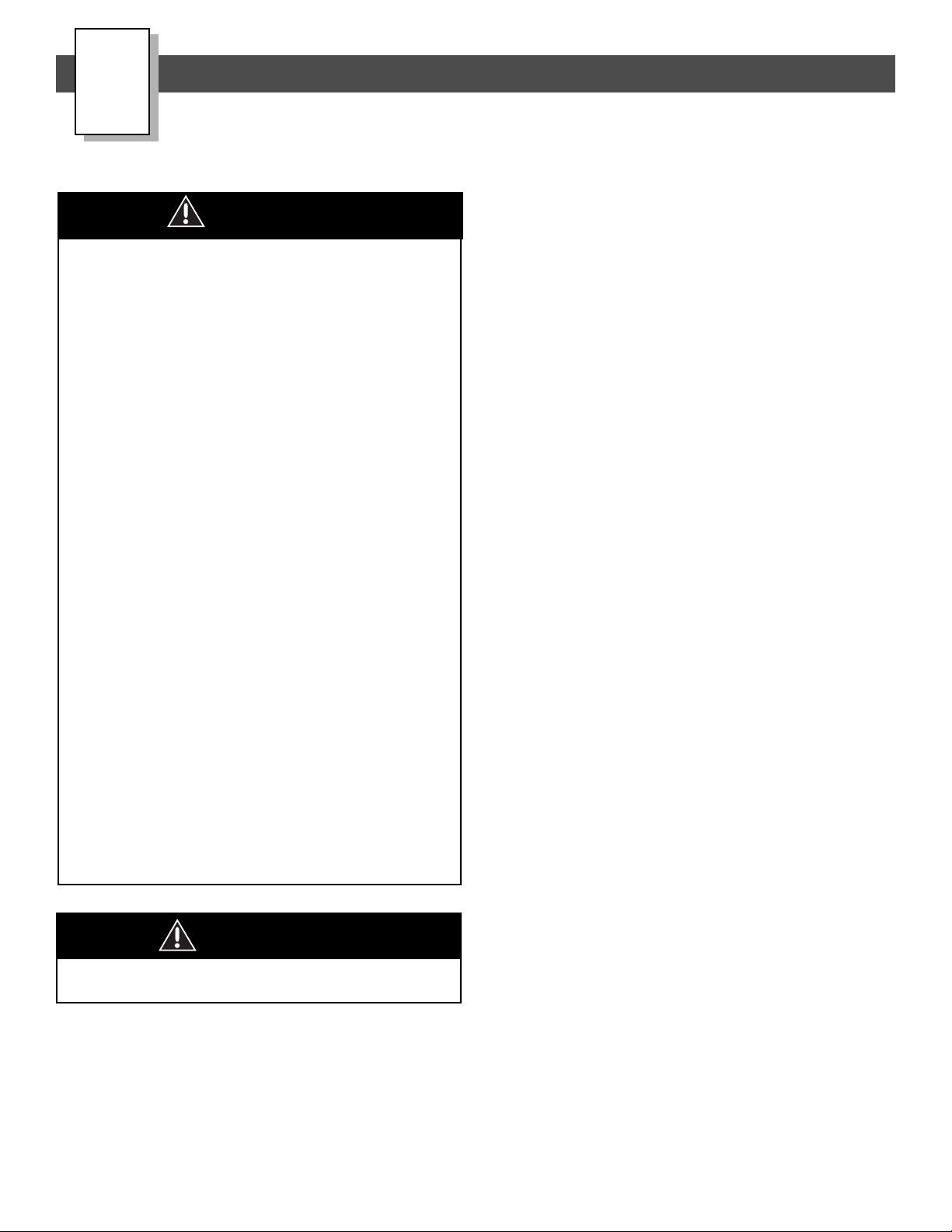
Page 3
3
CAUTION
• In the unassembled state, this package contains small parts. Adult assembly is required.
• Use the charger in dry locations only.
WARNING
• Prevent Injuries and Deaths
• Direct Adult Supervision Required
• Keep Children Within Safe Riding Areas.
These areas must be:
- away from swimming pools and other bodies of water to prevent drownings
- generally level to prevent tipovers
- away from steps, driveways, cars, roads and alleys.
RIDING HAZARD
WARNING
• Battery can fall out and injure a child if vehicle tips over. Always use battery clamp.
• PREVENT FIRE
- Never modify the electrical system. Alterations could cause a fire resulting in serious
injury and could also ruin the electrical system.
- Use of the wrong type battery or charger could cause a fire or explosion resulting in
serious injury.
- Use of Power Wheels
®
components in products other than Power Wheels®vehicles
could cause overheating, fire or explosion.
• The battery must be handled by adults only. The battery is heavy and contains sulfuric
acid (electrolyte). Dropping the battery could result in serious injury.
•Never allow children to charge the battery. Battery charging must be done by adults only.
A child could be injured by the electricity involved in charging the battery.
• Read the safety instructions on the battery.
• Examine the battery, charger and their connectors for excessive wear or damage each time
you charge the battery. If damage or excessive wear is detected, do not use the charger or
the battery until you have replaced the worn or damaged part.
• HOT motors. Handle carefully.
Warnings and Cautions
B
ELECTRICAL HAZARD
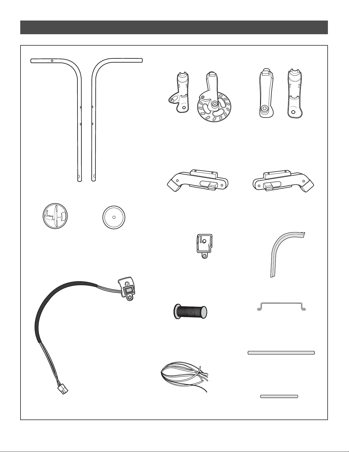
Page 4
4
Steering Bushing - 2
Steering Stop
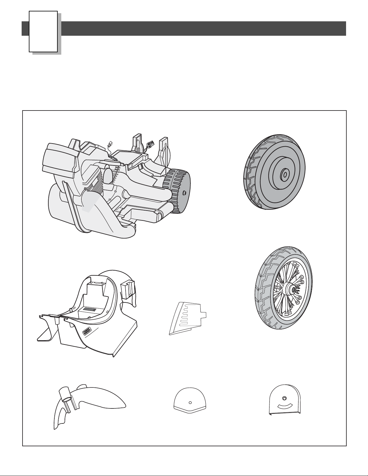
Parts
C
Rear Wheel
• If you experience a problem with this product, or are missing a part, please call us at 1-800-348-0751, rather than
return this product to the store.
• Please identify all parts before assembly and save all packaging material until assembly is complete to ensure that no
parts are discarded.
•Metal parts have been coated with a lubricant to protect them during shipment. Wipe all metal parts with a paper towel
to remove any excess lubricant.
T
M
Vehicle Body
Fender
Left Footboard
Vehicle Frame
Front Wheel
Page 5
5
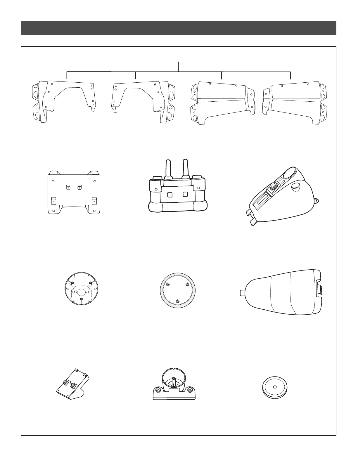
Exhaust Pipe Set
Parts
Tachometer Housing
Sound Box
Tachometer Cover
Front Fork Cover
Tank
Seat
Front Fork
Headlight Lens
Headlight Housing
Right - Outer Half
Left - Outer Half
Right - Inner Half
Left - Inner Half
Page 6
6
Handgrip - 2
Handlebar Harness
Parts
Right Shock SetLeft Shock Set
InnerOuter
Inner Outer
Left
Handlebar
Right
Handlebar
Tassel - 2
Left Strut
Signal Housing - 2
Switch Cover
Right Strut
Signal Lens - 2
Wheel Axle - 2
Fork Axle
Wire Cover
Battery Clamp
Page 7
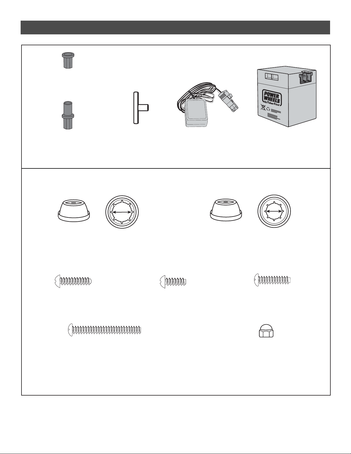
7
12 Volt Battery
Extended Hex Bushing - 2
Not Shown: Label Sheet
12-VOLT
CHARGER
12 Volt Charger
Axle Bushing - 2
Parts
All Shown Actual Size
.354 (Small Diameter) Cap Nut - 2*
.437 (Large Diameter) Cap Nut - 4*
*For your convenience, two extra .437 (large diameter) cap nuts, one extra .354 (small diameter) cap nut,
one extra #8 x
1
/2" screw and one extra #8 x 3/4" plastite screw are included.
Note: Tighten and loosen all screws with a Phillips screwdriver. Do not over-tighten the screws.
#8-32 Acorn Nut – 4
#8 x 3/4" Plastite Screw – 57*
#8-32 x 3/4" Machine Screw – 2
#8-32 x 15/8" Machine Screw – 2
#8 x 1/2" Screw – 2
Hex Bushing - 2
Pb
Page 8
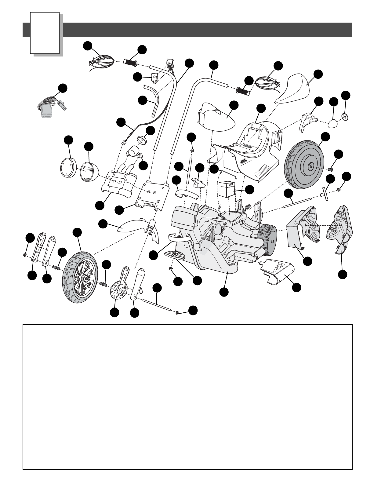
8
T
M
Parts Diagram
D
1. Vehicle Frame
2. Vehicle Body
3. Seat
4. Rear Wheel
5. Tank
6. Left Footboard
7. Exhaust - Inner Half - 2
8. Exhaust - Outer Half - 2
9. 12 Volt Battery
10. Axle Bushing - 2
11. Hex Bushing - 2
12. Wheel Axle - 2
13. Tassel - 2
14. Steering Bushing - 2
15 Headlight Lens
16. Headlight Housing
17. Left Handlebar
18. Right Handlebar
19. Front Fork
20. Handgrip - 2
21. Extended Hex Bushing- 2
22. Steering Stop
23. Fork Axle
24. Front Fork Cover
25. Fender
26. Tachometer Housing
27. Tachometer Cover
28. 12 Volt Charger
29. .354 Cap Nut - 2
30. .437 Cap Nut - 4
31. Battery Clamp
32. Left Strut
33. Handlebar Harness
34. Signal Housing - 2
35. Signal Lens - 2
36. Switch Cover
37. Wire Cover
38. Front Wheel
39. Right Inner Shock
40. Right Outer Shock
41. Left Inner Shock
42. Left Outer Shock
43. Sound Box
Not Shown
#8 x
3
/4" Screw - 57
#8 x 1/2" Screw - 2
#8-32 x 3/4" Machine Screw - 2
#8-32 x 15/8" Machine Screw - 2
#8-32 Acorn Nut - 4
Label Sheet
5
2
28
3
16
15
19
17
13
23
6
12
7
8
1
21
42
12
22
29
4
20
24
14
29
43
31
9
41
39
40
30
30
14
21
38
32
25
18
33
36
13
20
37
34
35
26
27
10
30
11
Note: Some parts shown are assembled
on both sides of the vehicle.
12-VOLT
CHARGER
Page 9
9
Battery Charging
E
Important Notes
•Your new battery must be charged for at least
18 hours before you use it in your vehicle for
the first time.
•We recommend that you start charging your battery
before beginning assembly of your new vehicle.
•The battery must be upright while charging.
• The charger is not a toy.
• Do not short circuit the battery.
•You do not need to remove the battery from your vehicle
to recharge it.
• Before charging the battery, examine the battery case for
cracks and other damage which may cause sulfuric acid
(electrolyte) to leak during the charging process. If
damage is detected, do not charge the battery or use it
in your vehicle. Battery acid is very corrosive and can
cause severe damage to surfaces it contacts.
• Do not charge the battery on a surface (such as kitchen
counter tops) which could be damaged by the acid
contained inside the battery. Take precautions to protect
the surface on which you charge your battery.
• If your battery is old and will not accept a charge, do not
leave it in your vehicle. Always remove a dead battery
from the vehicle.
• Use only a Power Wheels®12 volt charger (120 VAC
60 Hz 28W with an output of 12 VDC 1200mA) to
charge your Power Wheels®12 volt battery.
• When replacing the 12 volt battery, use only a
Power Wheels®12 volt battery.
About Thermal Fuses
Yo ur Power Wheels 12 volt battery is equipped with a
built-in thermal fuse. The thermal fuse is a self-resetting
safety device which automatically “trips” and shuts down
operation of the vehicle if the vehicle is overloaded or the
driving conditions too severe. Once a fuse has “tripped”,
it will automatically reset itself after approximately 25
seconds and allow the vehicle to resume normal
operations. To avoid repeated automatic shutdowns,
do not overload the vehicle by exceeding the 65 lbs.
maximum weight capacity or by towing anything behind
the vehicle. Avoid severe driving conditions, such as
driving up slopes or running into fixed objects, which
can cause the wheels to stop spinning while power is still
being supplied to the motors and make sure your child
stops the vehicle before switching speeds or direction.
If a thermal fuse in a battery continually trips under
normal driving conditions, please contact your local
Power Wheels®Authorized Service Center. For the
location of the Authorized Service Center nearest to
you, please visit us on-line at www.powerwheels.com,
or call 1-800-348-0751.
CAUTION
Use the charger in dry locations only.
WARNING
• Battery can fall out and injure a child if
vehicle tips over. Always use battery clamp.
• PREVENT FIRE
- Never modify the electrical system.
Alterations could cause a fire resulting in
serious injury and could also ruin the
electrical system.
- Use of the wrong type battery or
charger could cause a fire or explosion
resulting in serious injury.
- Use of Power Wheels
®
components in
products other than Power Wheels
®
vehicles could cause overheating,
fire or explosion.
• The battery must be handled by adults only.
The battery is heavy and contains sulfuric
acid (electrolyte). Dropping the battery could
result in serious injury.
•Never allow children to charge the battery.
Battery charging must be done by adults
only. A child could be injured by the
electricity involved in charging the battery.
• Read the safety instructions on
the battery.
• Examine the battery, charger and their
connectors for excessive wear or damage
each time you charge the battery. If damage
or excessive wear is detected, do not use
the charger or the battery until you have
replaced the worn or damaged part.
ELECTRICAL HAZARD
Page 10
10
Battery Charging
T
M
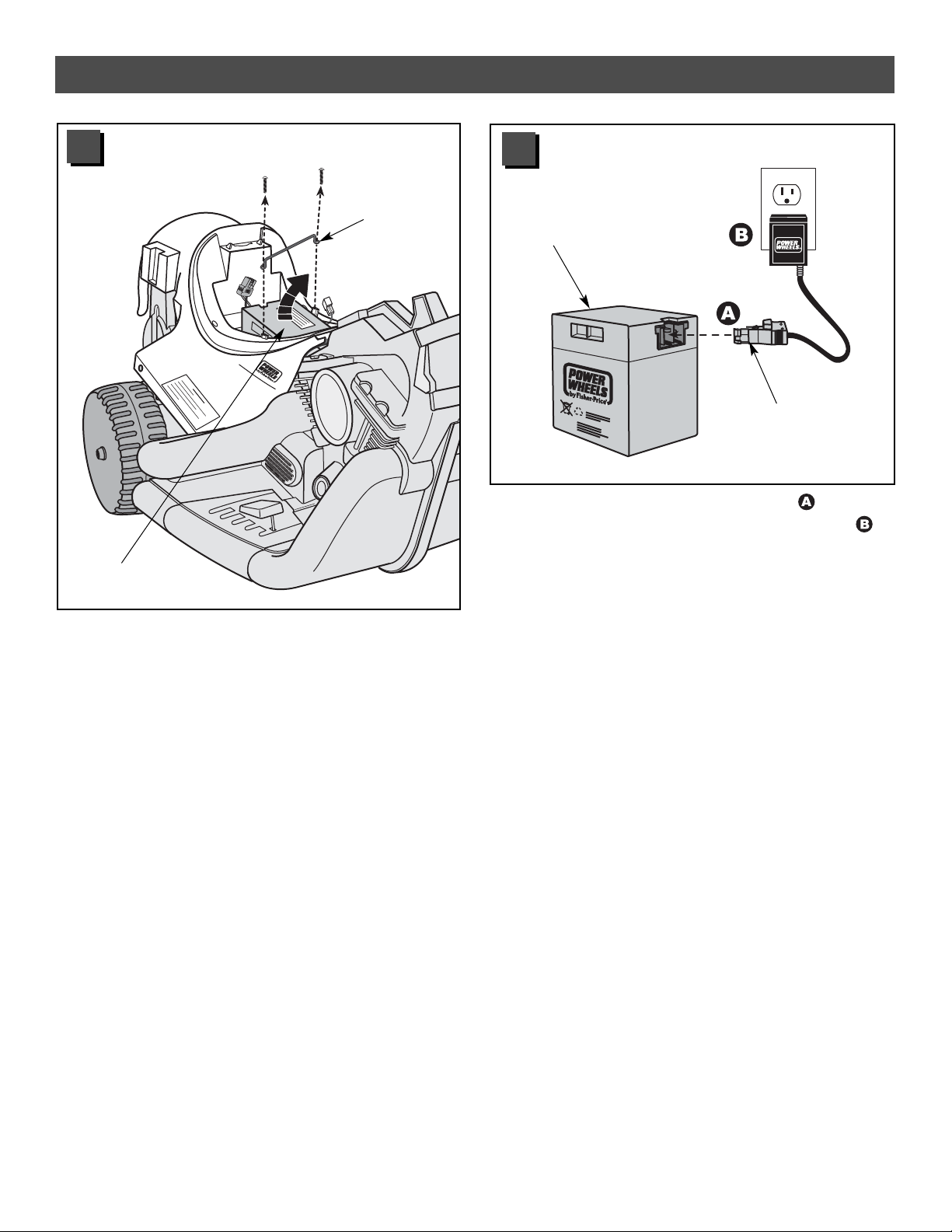
• Plug the charger connector into the battery .
• Plug the charger into a standard 120 volt wall outlet .
Note: If power flow to the wall outlet is controlled by a
switch, make sure the switch is “ON”.
•Before first-time use, charge the battery for at least 18
hours. Never charge the battery longer than 30 hours.
• Recharge the battery for at least 14 hours after each
use of your vehicle. Do not charge the battery longer
than 30 hours.
• Once the battery is charged, pull firmly on the charger
connector to disconnect it from the battery. Unplug the
charger from the wall outlet. The battery is now ready to
be installed in your vehicle. Please see the Battery
Installation section on page 30 for detailed instructions on
installing your battery. If your battery is already installed in
your vehicle, simply plug the motor harness connector
into the battery and replace the seat.
• Remove the two screws holding the battery clamp to the
vehicle body.
• Remove the battery clamp. Set the battery clamp and
screws aside. Do not throw out the battery clamp or
screws.You will use them when installing your battery
(see page 30).
• Remove the battery from the battery compartment.
• Remove and discard any cardboard in battery compartment which may have been added for shipping purposes.
Battery
Charger
Connector
Battery
Battery
Clamp
1
2
Pb
Page 11
11
Assembly
F
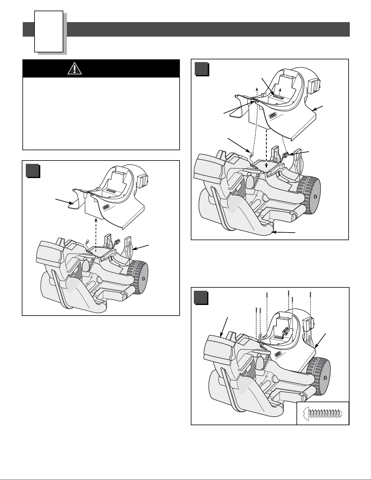
Children can be harmed by small parts,
sharp edges and sharp points in the
vehicle’s unassembled state, or by
electrical items. Care should be taken in
unpacking and assembly of the vehicle.
Children should not handle parts,
including the battery, or help in
assembly of the vehicle.
WARNING
T
M
• Lift to remove the vehicle body from the vehicle frame.
Vehicle
Frame
Vehicle
Body
1
T
M
•Position the vehicle body on top of the vehicle frame.
• Fit motor harness connector up through the large
rectangular opening in the vehicle body.
• Fit the high speed hook-up connector through the
square opening near the front of the vehicle body.
Square
Opening
Motor
Harness
Connector
Vehicle Frame
Vehicle
Body
Large
Rectangular
Opening
High Speed
Hook-Up
2
T
M
•Insert six #8 x 3/
4" screws through the vehicle body and
into the vehicle frame. Make sure the holes in the
vehicle body and frame are aligned. Tighten the screws.
Vehicle
Frame
Vehicle
Body
3
Page 12
12
Assembly
T
M
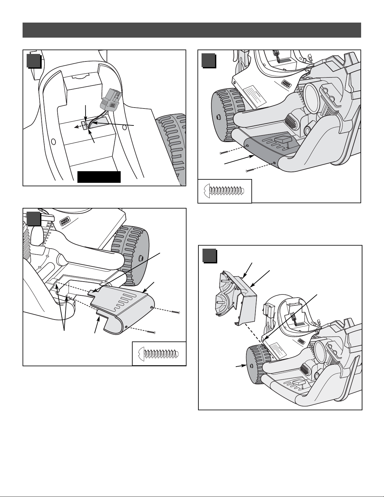
• Fit the motor harness between the vehicle body tabs.
Motor
Harness
Ta b
Ta b
Top View
• Fit the tabs on the left footboard into the slots in the left
side of the vehicle frame. Make sure both tabs are in
the slots.
Hint: You may need to squeeze the left footboard in order
to align the tabs with the slots.
•Insert two #8 x 3/4" screws into the left footboard as
shown. Tighten the screws.
Left
Footboard
Ta b
Ta b
Slots
4
5
T
M
• The right footboard was inserted in the vehicle frame at
the factory. Make sure the right footboard is in place.
•Insert two #8 x 3/4
" screws into the right footboard
as shown. Tighten the screws.
Right
Footboard
6
• Separate the exhaust pipe set pieces. Note the
R (right side) and L (left side) markings on the inside
of each piece.
• Fit the inner half of the right exhaust pipe (R) over the
stabilizer wheel on the right side of the vehicle. Make
sure the peg on the inner exhaust pipe fits into the
hole in the vehicle body.
T
M
Stabilizer
Wheel
Vehicle
Body Hole
Right Exhaust
Pipe - Inner Half
Peg
7
Page 13

13
Assembly
T
M
Right Exhaust
Pipe - Outer Half
• Fit the outer half of the right exhaust pipe (R) to the
inner half of the right exhaust pipe.
Hint: Use a long-shaft Phillips screwdriver to complete
this assembly step.
• Align the holes in the inner half of the right exhaust pipe
with the holes in the vehicle frame.
•Insert four #8 x
3
/4" screws through the inner half of the
right exhaust pipe and into the vehicle frame.
IMPORTANT! The screw marked with an asterisk *in the
illustration above must go through the hole in the inner
half of the right exhaust pipe, the vehicle body and into
the vehicle frame. Make sure all the holes are properly
aligned and the screw goes through all three parts.
• Tighten the screws.
T
M
Vehicle
Frame
Right Exhaust
Pipe - Inner Half
*
8
9
TM
Right Exhaust
Pipe
• With the holes of both halves aligned, insert six #8 x 3/
4"
screws to join the two halves of the right exhaust pipe.
• Tighten the screws.
• Repeat steps 7 through 10 to assemble the left exhaust
pipe (L) to the left side of the vehicle.
10
Right
Strut
Right Rear
Fender
• Fit the right strut onto the right rear fender of the
vehicle body.
•Insert two #8 x 3/4" screws into the top of the right strut
and tighten.
11
Page 14

Assembly
15
Strut
Rear
Fender
#8-32 x 1
5
/8"
Machine Screw
#8-32 x
3
/4"
Machine Screw
• First, insert a #8-32 x 15/8" machine screw through the
hole in the side of the right strut that is closest to the
rear of the vehicle body, as shown .
• Attach an #8-32 acorn nut to the end of the screw,
inside the rear fender. Hand-tighten the acorn nut.
• Then, insert a #8-32 x 13/4" machine screw through the
hole in the side of the right strut that is towards the front
of the vehicle body, as shown .
• Attach an #8-32 acorn nut to the end of the screw,
inside the rear fender. Hand-tighten the acorn nut.
• Using an adjustable wrench to hold the acorn nuts
inside the rear fender, tighten the screws.
• Repeat steps 11 and 12 to assemble the left strut to the
left rear fender of the vehicle body.
12
Strut
Signal
Housing
• Slide a signal housing onto a strut.
• Bend the tab inside the signal housing down.
13
Strut
Signal
Lens Rib
Signal
Housing
Notch
• Align the rib on the signal lens with
the notch in the signal housing.
Fit the lens into the housing.
•Insert a #8 x 3/4" screw into the lens
and tighten.
• Repeat steps 13 and 14 to assemble the other signal
housing and signal lens to the other strut.
14
Signal
Lens
Signal
Housing
Bend
Ta b
Down
Back View
Back View
Wheel
1
1
2
2
4
4
3
3
Guide
Guide
Guide
Guide
• Before applying labels to the rear wheel, wipe it with
a clean, dry cloth to make sure it is free of dirt and oils.
Make sure your hands are clean.
• Apply labels to both sides of the wheel as shown in
the illustration.
IMPORTANT! Labels 1 and 2 are designed to slightly
overlap; and labels 3 and 4 are designed to slightly
overlap. For each side, apply label 1 before applying label
2. Align the edge of label 2 with the guide marks
on label 1. Apply label 3 before applying label 4. Align the
edge of label 4 with the guide marks on label 3.
14
Page 15
15
Assembly
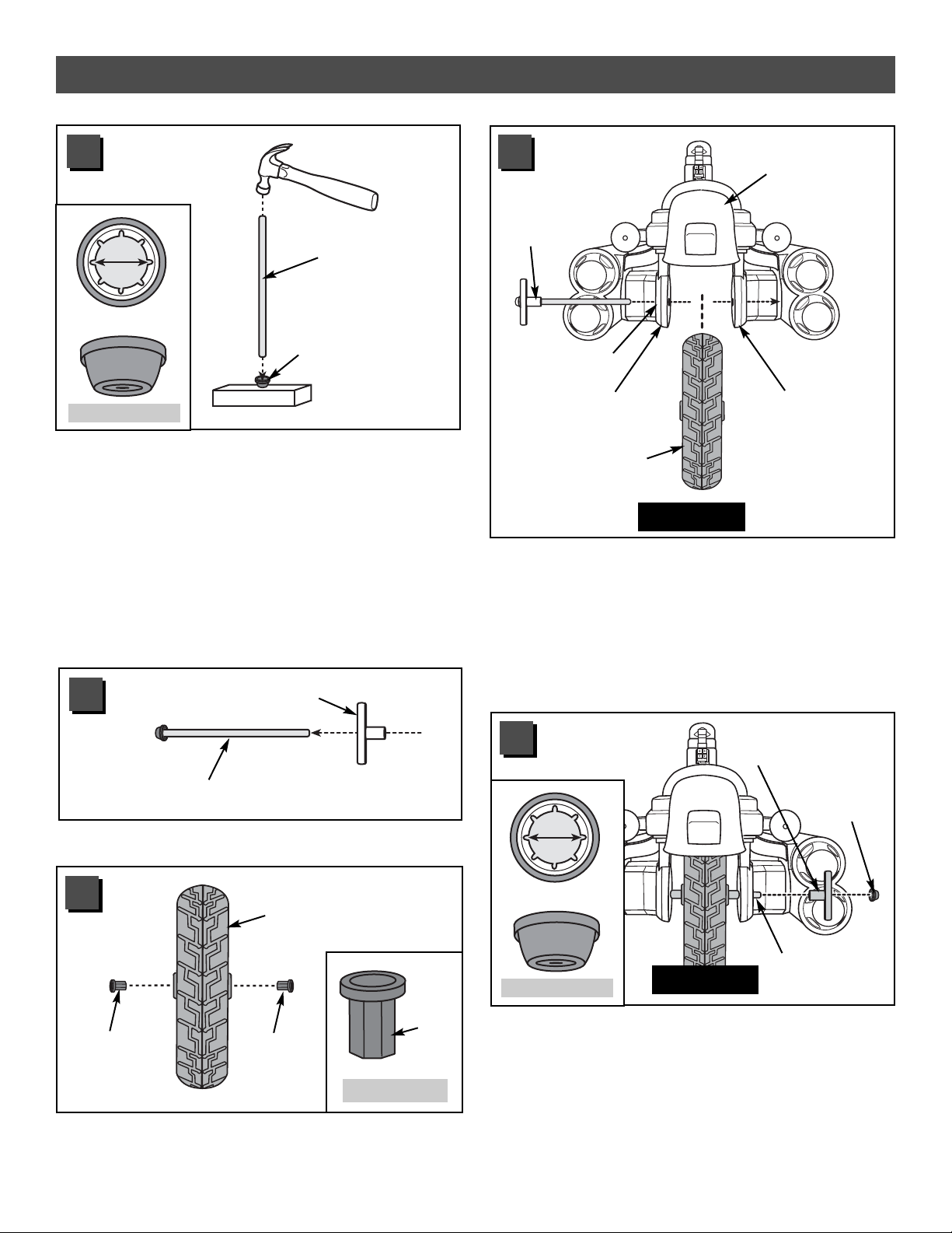
• Slide an axle bushing, flat side first, on the wheel axle.
Axle Bushing Flat Side
Wheel Axle
Rear
Wheel
Hex
Bushing
Hex
Bushing
• Fit two hex bushings, barrel side first, into the hole in
the rear wheel.
• Separate the fork axle from the two wheel axles. (The
fork axle is shorter than the wheels axles.) Set the fork
axle aside for assembly step 39.
• Place a .437 (large diameter) cap nut on a flat surface,
inside up. Fit the end of a wheel axle into the cap nut.
•Tap the opposite end of the wheel axle with a hammer
to secure the cap nut on the axle. Pull on the cap nut
to make sure it is secure.
• Repeat this procedure to assemble a .437 (large
diameter) cap nut to one end of the other wheel axle.
• Set one of the wheel axles aside for assembly step 52.
Wheel Axle
.437 (Large Diameter)
Cap Nut
.437"
.437 Cap Nut
Hex Bushing
16
17
18
.437 (Large
Diameter)
Cap Nut
Axle Bushing
Tube Side
Wheel Axle
• Slide an axle bushing, tube side first, onto the end of the
wheel axle. Make sure the flat end of the axle bushing
fits into the groove in the rear fork arm.
• Fit a .437 (large diameter) cap nut on the end of
the wheel axle. Tap the .437 cap nut with a hammer to
secure it on the end of the wheel axle.
Hint: You may need the help of another adult to support
the other end of the wheel axle.
• Pull on the .437 cap nut to make sure the rear wheel
assembly is secure.
Back View
Axle
Bushing
Vehicle
Frame
Rear Fork Arm
Groove
Rear Fork Arm
Rear Wheel
(with Hex Bushings)
•Position the vehicle assembly so that the back is
facing you.
• While holding the hex bushings in place, position the rear
wheel between the rear fork arms of the vehicle frame.
• Slide the wheel axle (with axle bushing) through one rear
fork arm, through the wheel (with hex bushings) and out
through the other rear fork arm. Make sure the wheel
axle bushing fits into the groove in the rear fork arm.
Back View
.437"
.437 Cap Nut
19
20
Barrel
Side
Page 16

16
Assembly
T
M
Steering
Bushing
Vehicle
Frame
Neck
•Position the vehicle frame so that the front faces you.
• Fit a steering bushing underneath the neck of the
vehicle frame.
•Insert a #8 x
3
/4" screw into each end of the steering
bushing and tighten.
Front View
21
• Fit the headlight lens onto the headlight housing.
•Insert three #8 x 3/4" screws into the headlight lens
and tighten.
Headlight
Lens
Headlight
Housing
22
Front Fork
Lower Hole
Lower
Hole
Front Fork
Cover
• Fit the front fork into the front fork cover.
•Insert two #8 x 1/2" screws into the lower holes in the
front fork and tighten.
23
24
Headlight
Assembly
Center
Holes
Front Fork
Assembly
•Position the headlight assembly with the lens down on a
flat surface.
•Fit the front fork assembly onto the back of the headlight
assembly, as shown.
•Insert two #8 x
3
/4" screws through the center holes in
the front fork assembly and into the headlight assembly.
• Tighten the screws.
Page 17

17
Assembly
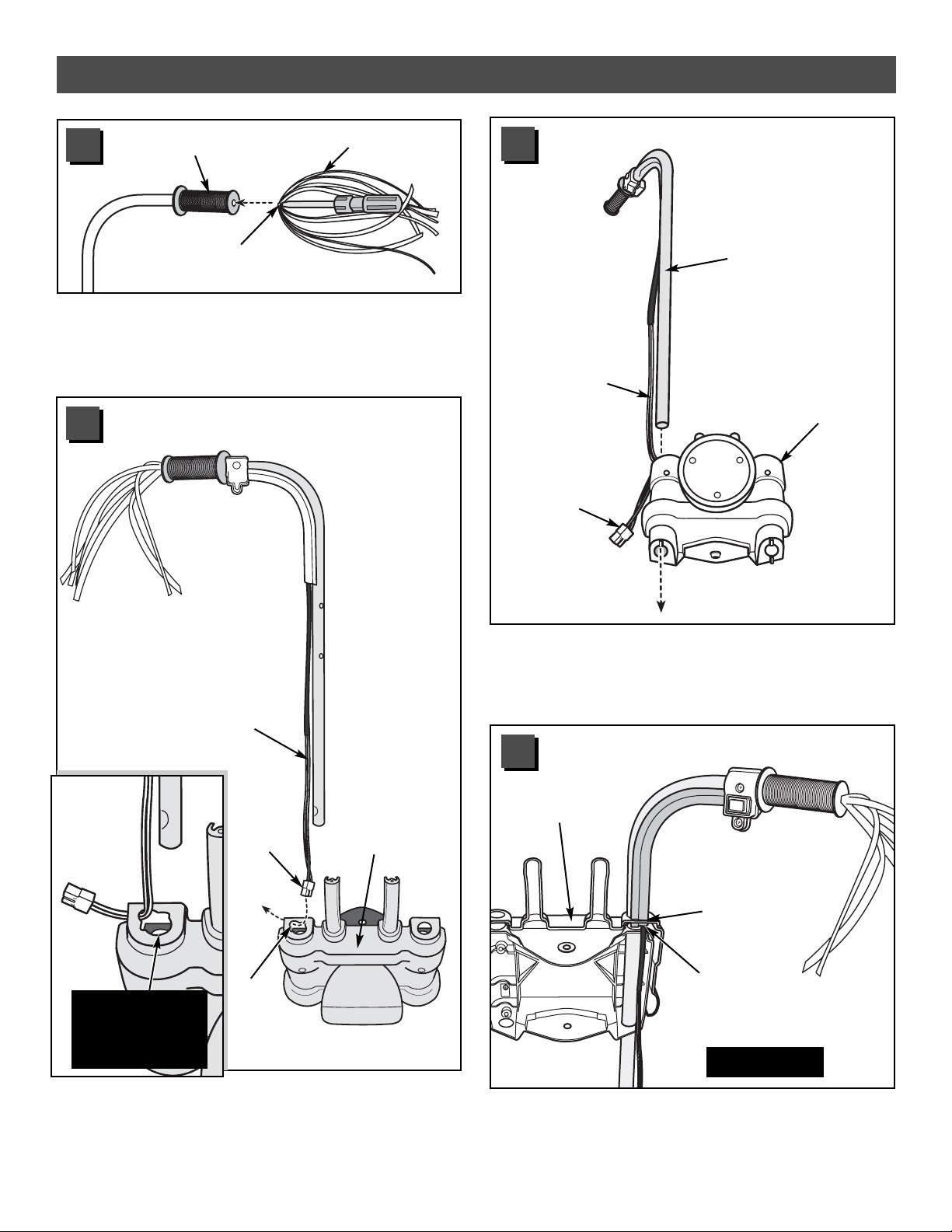
Wire
Cover
Switch
Switch
Peg
Switch
Cover
• Fit the wrapped portion of the handlebar harness into
the wire cover.
• Fit the tab on the wire cover into the notch in the switch
to lock the two parts together.
Handlebar
Harness
25
Right
Handlebar
• Locate the right handlebar. The right handlebar has an
additional hole in the grip area.
• Fit the switch to the right handlebar, making sure the
screw hole in the switch aligns with the screw hole in
the right handlebar.
Switch
Cover
26
• Fit the switch cover peg through the hole in the right
handlebar and the switch.
• While holding the two parts firmly together, insert
two #8 x 3/
4" screws into the switch and tighten.
27
• Fit a handgrip on the end of each handlebar.
Hint: If it is difficult to slide the handgrips onto the handlebars, moisten the inside of the handgrips with water.
Handgrip
Handgrip
Handlebars
28
Wire
Cover
Ta b
Switch
Notch
Additional Hole
in Grip Area
Right Handlebar
Page 18
18
Assembly
Tassel
Staple
Handgrip
• Using a slotted screwdriver, push the staple in the center
of a tassel into the hole in the end of a handgrip.
• Repeat this procedure to attach the other tassel to the
other handlebar.
29
Plug
Fork Cover
•Position the front fork so that it is upright and facing you.
•Insert the handlebar harness plug through the upper
hole in the front fork. Do not insert the plug through
the lower hole in the front fork.
Handlebar
Harness
Upper
Hole
30
•Turn the front fork assembly around so the back is
facing you.
• Slide the end of the wire cover into the upper hole in the
front fork, as shown.
• While making sure the handlebar harness plug remains
inserted through only the upper hole in the front fork,
slide the right handlebar down through the upper and
lower holes in the front fork.
Front
Fork
Handlebar
Harness
Plug
Right
Handlebar
Handlebar
Harness
31
32
Back View
Front Fork
Assembly
Upper Hole in
Front Fork
End of
Wire Cover
DO NOT insert
the plug through
the lower hole in
the front fork!
Page 19

19
Assembly
• Fit the handlebar harness plug
up through the rectangular hole
in the vehicle body.
TM
Handlebar
Harness Plug
Rectangular Hole
See
Inset
Handlebar
Harness Plug
Rectangular Hole
35
• Align the screw holes in each handlebar with the screw
holes in the front fork.
• First, insert two #8 x 3/4" screws through the lower holes
in the front fork and into each lower hole in each handlebar
and hand tighten. Do not tighten the screws completely.
These screws will be tightened in step 54.
•Next, insert two #8 x 3/4" screws through the upper holes
in the front fork and into each upper hole in each handlebar
and hand tighten. Do not tighten the screws completely.
These screws will be tightened in step 54.
Handlebars
Handlebar
Harness
34
•Turn the front fork around so the front is facing you.
• Slide the left handlebar through the upper and lower
holes in the front fork.
Front Fork
Left
Handlebar
33
M
T
Page 20

20
Assembly
.354 (Small Diameter)
Cap Nut
Fork Axle
• Place a .354 (small diameter) cap nut on a flat surface,
inside up. Fit the end of the fork axle into the cap nut.
•Tap the opposite end of the fork axle with a hammer to
secure the cap nut on the axle. Pull on the cap nut to
make sure it is securely assembled.
.354"
.354 Cap Nut
39
T
M
Steering
Stop
Neck of
Vehicle Body
• First, fit the tab on the steering stop into the curved slot
in the lower steering bushing .
• Hold the steering stop in place.
• Then, slide the handlebar assembly on the vehicle frame
neck and over the steering stop
.
Handlebar
Assembly
38
TM
Ta b
Handlebar
Harness
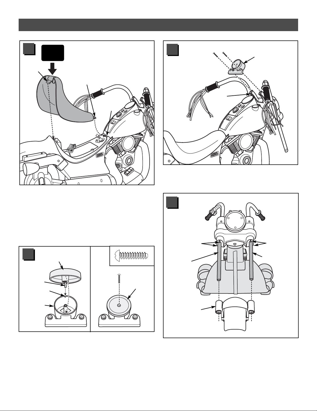
• Fit the handlebar harness behind
the tab in the vehicle frame neck.
See
Inset
Ta b
Handlebar
Harness
36
T
M
• Fit the remaining steering bushing onto the top of the
vehicle frame neck.
•Insert two #8 x 3/4" screws into each end of the steering
bushing and tighten.
Steering
Bushing
37
Page 21

21
•Insert the handlebar harness into
the wire clip on the side of the
vehicle body.
Assembly
T
M
Wire
Clip
Handlebar
Harness
See
Inset
Wire
Clip
Handlebar
Harness
41
T
M
• Slide the fork axle up through the bottom of the front
fork, through the frame neck and steering stop, and out
the top of the front fork.
• Fit a .354 (small diameter) cap nut on the end of the
fork axle.
• Support the fork axle and tap the cap nut with a hammer
to secure it on the end of the axle.
Hint: You may need the help of another adult to hold the
front axle in place while you secure the cap nut.
• Pull on the .354 cap nut to make sure it is secure on the
fork axle.
.354 (Small Diameter)
Cap Nut
Fork Axle
Front Fork Assembly
.354 Cap Nut
40
.354"
Page 22

22
Assembly
T
M
•Insert a #8 x 3/4" screw through the hole in each side of
the tank and tighten.
Hint: To replace the batteries in the sound box, simply
remove the screws from the tank and remove the tank
from the vehicle frame. After replacing the batteries, be
sure to replace the sound box, tank and screws.
Tank
Vehicle
Frame
T
M
• Balance the sound box on the vehicle body. (The speaker
should face down.)
• Fit the tabs at the bottom of the tank under the front end
of the vehicle body.
•Lower the tank on the vehicle frame, making sure that the
two small square openings in the tank fit over the buttons
on the sound box.
Sound Box
Buttons
Tabs
Tank
43
44
• Loosen the screw in the sound box battery compartment
door using a Phillips screwdriver and open the battery
compartment.
•Insert three “AA” (LR6) alkaline batteries in the
sound box.
Hint: For longest battery life, use only alkaline batteries.
• Close the battery compartment door and tighten the
screw using a Phillips screwdriver. Do not over-tighten.
Sound Box
Battery
Compartment
Battery
Compartment
Door
SHOWN ACTUAL SIZE
1.5V x 3
“AA” (LR6)
Battery Tips
Batteries may leak fluids that can cause chemical burn
injury or ruin your product. To avoid battery leakage:
• Do not mix old and new batteries or batteries of
different types: alkaline, standard (carbon-zinc) or
rechargeable (nickel-cadmium).
•Insert batteries as indicated inside the battery
compartment.
• Remove batteries during long periods of non-use.
Always remove exhausted batteries from the product.
Dispose of batteries safely. Do not dispose of batteries
in a fire. The batteries may explode or leak.
•Never short-circuit the battery terminals.
• Non-rechargeable batteries are not to be recharged.
• Use only batteries of the same or equivalent type as
recommended.
• Do not charge non-rechargeable batteries.
• Remove rechargeable batteries from the product before
charging.
• If removable rechargeable batteries are used, they are
only to be charged under adult supervision
42
Page 23
23
• Slide the fender onto the ends of the handlebars. Make
sure the pegs on the fender slide over the tabs on the
front fork.
Handlebar
Front
Fork Tabs
Front
Fork Tabs
Handlebar
Fender
Assembly
48
• Fit the tachometer to the fork cover.
•Insert two #8 x 3/4" screws into the tachometer
and tighten.
Tachometer
Fork
Cover
47
• Fit the tachometer cover onto the tachometer housing.
The tab on the tachometer cover should fit into the notch
in the tachometer housing.
•Insert a #8 x 3/4" screw into the tachometer cover
and tighten.
Tachometer
Housing
Ta b
Notch
Tachometer
Cover
T
M
• Fit the tab on the front of the seat into the slot near
the tank.
• Push down firmly near the back of the seat to “snap” it
to the vehicle.
Hint: You will need to remove the seat to access the
high speed connectors and to charge the 12 volt battery.
To remove the seat, press the tab at the back of the seat
and lift.
Tank
Slot
Seat Tab
Seat Tab
45
46
Tachometer
Cover
PUSH
HERE
M
T
Page 24

24
• Fit two extended hex bushings, hex side first, into the
hole in the front wheel.
Extended
Hex Bushing
Extended
Hex Bushing
Front Wheel
Assembly
• While holding the extended hex bushings in place,
position the front wheel between the shocks.
• Being careful to keep the shocks correctly positioned,
align the holes in the shocks with the holes in the
handlebars. Slide the remaining wheel axle (with .437
cap nut assembled in step 16) through one shock.
Hint: If the hole in the shock and handlebar are not
aligned, the fender may not be properly positioned on the
front fork. Reposition the fender to align the holes.
Shock
Shock
Front Wheel
(with Extended Hex Bushings)
Wheel Axle
51
52
Extended Hex Bushing
Hex
Side
• The shock sets may be held together by rubber bands to
aid in assembly. After completing assembly step 50,
remove and throw away the rubber bands.
• Fit the inner and outer left shock halves together (they are
labeled on the inside with an “L”). Insert a #8 x 3/4" screw
into the hole in the outer left shock and tighten.
• Fit the inner and outer right shock halves together (they
are labeled on the inside with an “R”). Hold the halves
together until the next step.
Outer Right
Shock
Outer Left
Shock
Inner Right
Shock
Inner Left
Shock
49
• Fit the right shock assembly onto the end of the right
handlebar. Fit the left shock assembly onto the end of
the left handlebar.
• Push firmly to slide the shocks onto the handlebars
making sure that the tabs on the inner shock halves fit
into the grooves in the fender.
Hint: You will need the help of another adult to hold
the shocks and fender in place for the next two
assembly steps.
Left Shock
Right Shock
Grooves
Tabs
Right
Handlebar
Left
Handlebar
50
Page 25

25
• Continue to slide the wheel axle through the extended
hex bushing, wheel, extended hex bushing and then
the shock.
• Fit a .437 (large diameter) cap nut on the end of the
wheel axle.
• Support the opposite end of the wheel axle and tap the
cap nut with a hammer to secure it on the end of the
wheel axle.
• Pull on the .437 cap nut to make sure the front wheel
assembly is secure.
Shock
.437 (Large
Diameter)
Cap Nut
Wheel
Axle
.437"
.437 Cap Nut
53
• Completely tighten the four screws in the front handlebar
assembly to secure the handlebars.
Tighten
Screws
Tighten
Screws
54
Assembly
Page 26

26
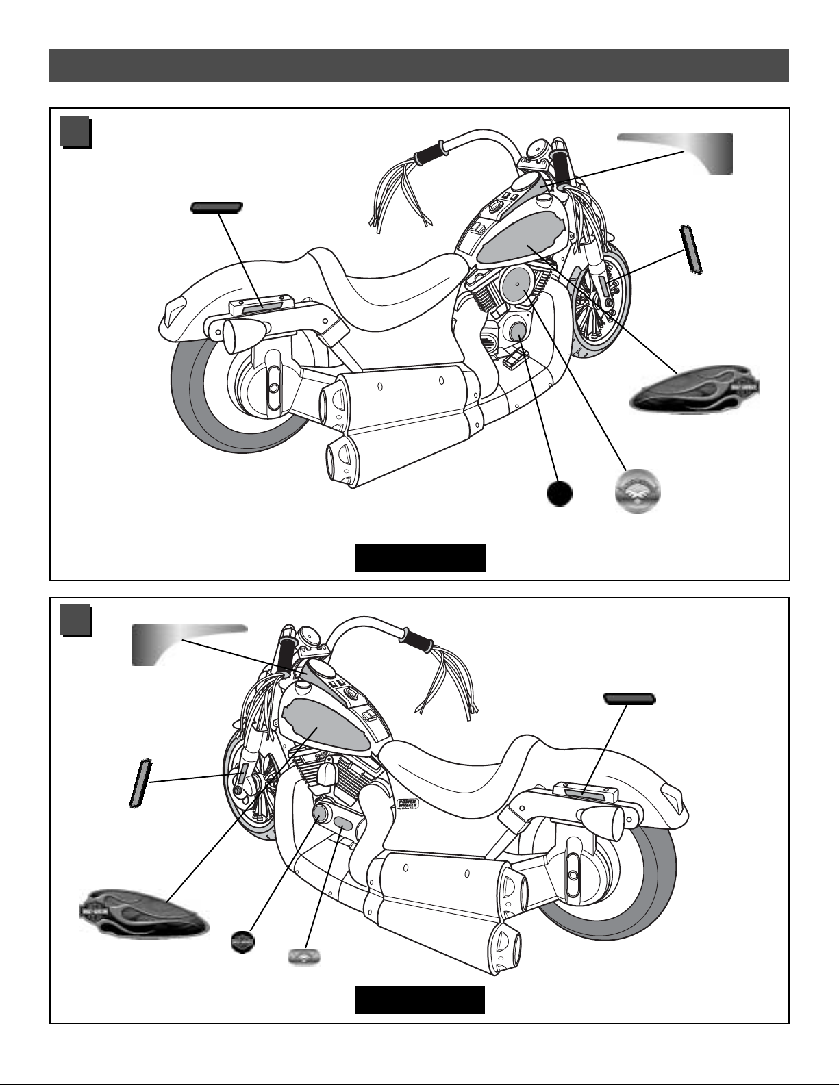
Label Decoration - Model B3160
G
Proper label application will help to keep the labels looking their best! When applying labels, keep the following
guidelines in mind:
•Wash your hands before applying the labels.
• Before applying the labels, wipe the surface of the vehicle with a clean, dry cloth to remove any dust or oils.
• Place the labels exactly as shown in the illustrations.
•For best results, avoid repositioning a label once it has been applied to the vehicle.
• After applying a label, rub the label firmly with a clean, dry cloth to make sure the label is adhered to your vehicle.
Start at the center of a label, and smooth towards the outer edges to remove air bubbles.
Front View
Console View
Back View
1 3
2
26
9
15
8
16
16
17
16
16
11
12
22
24
25
21
23
23
5
5
5
5
5
5
5
5
5
5
5
5
5
5
5
5
15
20
Page 27
Label Decoration - Model B3160
Left Side
Right Side
27
5
4
7
27
30
18
28
29
19
31
6
13
14
10
M
T
Page 28

28
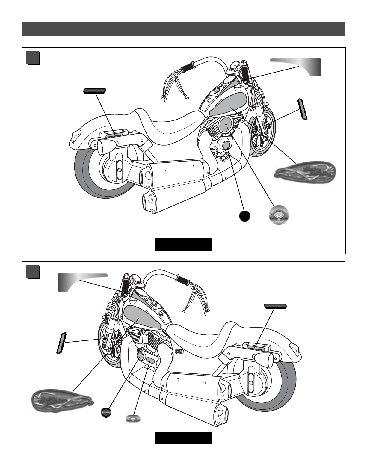
Label Decoration - Model B9784
Proper label application will help to keep the labels looking their best! When applying labels, keep the following
guidelines in mind:
•Wash your hands before applying the labels.
• Before applying the labels, wipe the surface of the vehicle with a clean, dry cloth to remove any dust or oils.
• Place the labels exactly as shown in the illustrations.
•For best results, avoid repositioning a label once it has been applied to the vehicle.
• After applying a label, rub the label firmly with a clean, dry cloth to make sure the label is adhered to your vehicle.
Start at the center of a label, and smooth towards the outer edges to remove air bubbles.
Front View
Console View
Back View
1 3
2
26
9
15
8
16
16
17
16
16
11
12
22
24
25
21
23
23
5
5
5
5
5
5
5
5
5
5
5
5
5
5
5
5
15
20
Page 29
Label Decoration - Model B9784
Left Side
Right Side
29
5
6
27
30
18
28
29
19
31
7
13
14
10
4
M
T
Page 30

30
IMPORTANT! Use only Power Wheels®12 volt battery.
Use of any other battery will damage your vehicle. Make
sure that you charge the battery for at least 18 hours using
the enclosed Power Wheels®12 volt charger before
operating your vehicle for the first time. Charge the
battery for at least 14 hours after each use of the vehicle.
Never charge the battery longer than 30 hours. Failure to
follow these instructions may damage your battery and will
void your warranty.
T
M
• Remove the seat. Press the tab at the back of the seat
and lift.
• Place the Power Wheels®12 volt battery upright in the
battery compartment. Make sure the battery terminals
face the rear of the vehicle.
•Fit the battery clamp over the battery.
•Insert a screw through each end of the battery clamp
and into the screw pegs in the vehicle body.
• Tighten the screws using a Phillips screwdriver.
Do not over-tighten.
T
M
• Plug the motor harness connector into the battery.
Push firmly to make sure the connector is secure in
the battery.
• Replace the seat on the vehicle.
Vehicle
Body
Power Wheels
®
12 Volt Battery
Battery
Compartment
Battery Installation
Battery Clamp
Screw
Peg
Screw
Peg
Battery
Motor
Harness
Connector
H
1
2
3
T
M
Page 31
31
If a battery leak develops, avoid contact with the leaking
acid and place the damaged battery in a plastic bag. See
information below for proper disposal.
If acid comes in contact with skin or eyes, flush with
cool water for at least 15 minutes and call a physician.
If acid is internally ingested, give water, milk of
magnesia or egg whites immediately. Never give emetics
or induce vomiting. Call a physician.
• Charge a new battery for at least 18 hours before first
use. Never charge the battery longer than 30 hours.
Overcharging or undercharging the battery may shorten
battery life and decrease vehicle running time.
• After the first charge, recharge the battery for at least
14 hours after each use. Never charge the battery
longer than 30 hours. Charge the battery after each
use, regardless of how long the vehicle was used.
•The battery must be upright while charging.
• Do not allow the battery to run down completely
before charging.
• Charge the battery before storing the vehicle.
• Charge the battery at least once per month, even if
the vehicle has not been used.
•Leaving the battery in a discharged condition will
ruin it.
• Always remove an exhausted battery from the vehicle.
Battery leakage and corrosion can damage the vehicle.
• Do not store the battery on a surface (such as kitchen
counter tops) which could be damaged by the acid
contained inside the battery. Take precautions to protect
the surface on which you store the battery.
• Do not store the battery in temperatures above 75° F or
below -10° F.
• Use only a Power Wheels
®
12 volt battery. Remember
to charge the new battery for at least 18 hours before
first use.
• Prevent the battery from moving freely inside the
battery compartment. Always use the battery clamp to
secure the battery in the battery compartment.
• Examine the battery, charger and their connectors for
excessive wear or damage each time you charge the
battery. If damage is detected, do not use the charger
or the battery until you have replaced the worn or
damaged part.
•Your Power Wheels
®
battery is sealed lead-acid battery.
They must be recycled or disposed of in an environmentally sound manner.
• Do not dispose of a lead-acid battery in a fire. The
battery may explode or leak.
• Do not dispose of a lead-acid battery in your regular,
household trash. The incineration, landfilling or mixing
of sealed lead-acid batteries with household trash is
prohibited by law in most areas.
• Return an exhausted battery to a federal or state
approved lead-acid battery recycler, such as a Power
Wheels®authorized service center or a local seller of
automotive batteries. For the authorized service center
location nearest to you, please call 1-800-348-0751.
Contact your local waste management officials for other
information regarding the environmentally sound
collection, recycling and disposal of lead-acid batteries.
If you live in the State of Florida or the State of Minnesota,
it is prohibited by law for anyone to throw away lead-acid
batteries in the municipal waste stream.
Care Disposal
Battery Care
and Disposal
I
Battery Care and Disposal
Caring
For Your Vehicle
J
• Check all screws, cap nuts and their protective coverings
regularly and tighten as required. Check plastic parts on
a regular basis for cracks or broken pieces.
• During snowy or rainy weather, the vehicle should be
stored inside or under a protective cover. Remember to
charge the battery at least once per month while your
vehicle is not in regular use.
•Avoid operating the vehicle in wet or snowy conditions,
and do not spray the vehicle with a hose. Do not wash
the vehicle with soap and water. Water or moisture in the
motors or electrical switches can cause them to corrode,
and could cause switch or motor failure.
•Avoid operating the vehicle on sand, loose dirt or gravel.
Sand, loose dirt or gravel in the motors or electrical
switches can cause them to jam, and could cause switch
or motor failure.
• The vehicle can be wiped down with a soft, dry cloth. For
a shiny finish, you can wipe plastic parts with a non-wax
furniture polish applied to a soft-cloth. Do not use
automotive wax. Do not use soap and water or spray the
vehicle with a hose.
•To ensure that your vehicle stays in good operating order,
we recommend that you periodically have your vehicle
checked by a Power Wheels®authorized service center.
For the location of the authorized service center nearest
to you, visit us on-line at www.powerwheels.com or
call 1-800-348-0751.
Page 32

32
Rules for Safe Driving
K
Teach Safety Rules to Children
While children can quickly develop the skill necessary to
drive this vehicle, it is important to remember that their
judgment skills are still very immature. Unsupervised
driving by children can lead to serious injury. Before
children use this vehicle, an adult should carefully
evaluate the driving area as well as the children’s skill
level and ability to drive this vehicle safely. Children are
not always able to recognize or anticipate hazards, even
when they have been taught about them. THERE IS NO
ACCEPTABLE SUBSTITUTE FOR DIRECT ADULT
SUPERVISION.
Teach appropriate safety rules to your child before
allowing operation of this vehicle. These rules should also
be reviewed with neighborhood children or other playmates
who want to drive this vehicle.
Riding Rules
Make sure children know and follow these rules for
safe driving:
1. Always sit on the seat.
2. Always wear shoes.
3. Only 1 (one) rider at a time. A child who is not sitting on
the seat or who is standing on the vehicle could fall off,
cause a tip-over or block the driver’s view. A child could
be seriously injured.
4. Do not allow any child to drive the vehicle in the street
or near moving (motorized) vehicles.
5. Do not allow any child to drive near bodies of water
(such as pools or creeks), obstructions (such as
furniture, low tree limbs or play equipment), or drop-offs
(such as stairs or decks).
6. Do not allow any child to drive the vehicle in the dark.
A child could encounter unexpected obstacles and have
an accident. Operate the vehicle only in the daytime or
a well-lit area.
7. Do not allow your child to drive on sloped or inclined
surfaces. Restrict your child’s driving to generally
level ground ONLY!
8. Do not allow your child to drive down or across a
steep slope.
- The vehicle may gain unsafe speed, even if the pedal
is released to stop.
- The vehicle may tilt and tip over.
- The wheels could lose traction, causing the vehicle
to slip.
9. Do not allow your child to drive up steep inclines. The
motor may stop and the vehicle could roll backwards at
an unsafe speed.
10. Never put anything near any moving parts. Rotating
parts such as motors, gear boxes and wheels can snag
fingers, hair, etc., causing serious injury. Do not allow
operation of the vehicle when it is on its side or in an
upside-down position.
11. Do not operate the vehicle near flammable vapors
(gasoline, paint thinner, acetone, liquid wax, etc.).
The vehicle’s electrical switches, like most electrical
switches, emit an internal spark when first turned on or
turned off. The presence of flammable liquids or vapors
could cause an explosion or a fire. Keep all flammable
products in tightly sealed containers and away from
the vehicle.
12. Do not allow a child to operate the vehicle without
direct adult supervision. To prevent unsupervised use of
the vehicle, disconnect the motor harness from the
battery when the vehicle is not in use.
WARNING
Prevent Injuries and Deaths
• Direct Adult Supervision Required.
•Keep Children Within Safe Riding Areas
These areas must be:
- away from swimming pools and other
bodies of water to prevent drownings.
- generally level to prevent tipovers.
- away from steps, cars, driveways,
roads and alleys.
RIDING HAZARD
Page 33

33
Reverse
• Press the DRIVE button on the tank.
• Press the foot pedal. The vehicle drives forward at a
maximum of 21/2 mph.
• Help your child practice steering to learn how far and
how quickly to turn the handlebar when driving forward
in low speed.
•Your vehicle has a patented, electronic braking system
that automatically stops the vehicle when your child’s foot
is lifted from the pedal.
• Make sure your child is comfortable with steering the
vehicle and automatically knows how to stop.
Beginner Use - Low Speed
To Stop
• Press the REVERSE button on the tank.
• Press the foot pedal. The vehicle backs-up at a
maximum of 21/2 mph.
Note: The vehicle is designed to operate in low speed
only in reverse.
• Help your child practice steering to learn how far
and how quickly to turn the handlebar when driving
in reverse.
How to Operate Your Vehicle
L
IMPORTANT! As assembled, your vehicle is ready to roll in low speed (21/2 mph, maximum). When
your child is ready to drive the vehicle in high speed (5 mph, maximum), follow the instructions
on this page to connect the high speed hook-up and use the power boost button.
To Back Up
Drive
IMPORTANT! To prevent damaging the motors and gears,
teach your child to stop the vehicle before switching
direction.Never shift from drive to reverse, or from
reverse to drive, without stopping.
Advanced Use - High Speed
• Remove the vehicle seat to access the high speed
hook-up.
• Plug the two high speed hook-up connectors together.
Make sure the two connectors are completely joined.
• Re-assemble the vehicle seat.
•To prevent operation of the vehicle in high-speed, simply
disconnect the high speed hook-up connectors.
T
M
High Speed
Hook-Up
Connectors
Page 34

34
Power Boost Button
• Press the power boost button to shift the vehicle into
high speed. The vehicle moves forward at a maximum
of 5 mph.
• Help your child practice steering to learn how far and
how quickly to turn the handlebar when driving forward
in high speed.
How to Operate Your Vehicle
Bumper-to-Bumper*
Limited Warranty
N
IMPORTANT! Your child should not drive the vehicle in
HIGH SPEED from a stopped position. Always start in
LOW SPEED. Then, press the power boost button to
shift to HIGH SPEED.
*One year limited warranty from the date of
purchase on the Power Wheels
®
vehicle.
Six month limited warranty on the
12 volt battery.
For the original purchaser, this one year limited warranty
covers the Power Wheels®ride-on vehicle (purchased from
Power Wheels®) against defects in materials and
workmanship. The six month limited warranty applies only
to the 12 volt battery included by Power Wheels®with the
original purchase of the vehicle.
This warranty covers normal use and does not cover the
Power Wheels®vehicle or battery if damaged by
unreasonable use, neglect, accident, abuse, misuse,
improper service or other causes not arising out of defects
in materials or workmanship. Evidence of any attempt at
consumer repair will void this warranty. This warranty does
not cover, and is intended to exclude, any liability on the
part of Power Wheels®, whether under this warranty or
implied by law or any indirect or consequential damages for
breach of warranty. Some states do not allow the exclusion
or limitation so this limitation may not apply to you.
Should you need service or assistance with your vehicle
during the warranty period, do not return the vehicle to
the store.Power Wheels®has provided a nationwide
network of authorized service centers. For a list of
authorized service centers, please visit us on-line at
www.powerwheels.com. Power Wheels®is continually
expanding our Authorized Service Center Network. If there
is not an authorized service center in your area, please call
Consumer Relations for information, 1-800-348-0751.
THIS WARRANTY GIVES YOU SPECIFIC LEGAL RIGHTS,
AND YOU MAY ALSO HAVE OTHER RIGHTS WHICH MAY
VARY FR OM STATE TO STATE.
PLEASE SAVE YOUR ORIGINAL SALES RECEIPT.
FCC Statement
(United States Only)
M
This equipment has been tested and found to comply with
the limits for a Class B digital device, pursuant to part 15
of the FCC rules. These limits are designed to provide
reasonable protection against harmful interference in a
residential installation. This equipment generates, uses
and can radiate radio frequency energy and, if not
installed and used in accordance with the instructions,
may cause harmful interference to radio communications.
However, there is no guarantee that interference will not
occur in a particular installation. If this equipment does
cause harmful interference to radio or television reception,
which can be determined by turning the equipment off and
on, the user is encouraged to try to correct the
interference by one or more of the following measures:
- Reorient or relocate the receiving antenna.
- Increase the separation between the equipment and
receiver.
- Connect the equipment into an outlet on a circuit
different from that to which the receiver is connected.
- Consult the dealer or an experienced radio/TV
technician for help.
Note: Changes or modifications not expressly approved by
the manufacturer responsible for compliance could void
the user's authority to operate
the equipment.
Advanced Use - High Speed
Page 35

35
Problem Possible Cause Solution
Vehicle does not run Undercharged battery Charge the battery. A new battery should have been
charged for at least 18 hours before using the vehicle for
the first time. After first-time use, recharge the battery for
at least 14 hours after each use. Never charge the battery
longer than 30 hours.
Check all connectors. Make sure the battery connector is
tightly plugged into the battery, and that the charger is
plugged into the wall.
Make sure power flow to the wall outlet is “ON”.
Charger is not working There is no sure way to tell if your charger is working unless
you have a volt meter. If you suspect there is a problem with
your charger, contact your local Power Wheels®authorized
service center. They can test your charger for you.
Tr ipped thermal fuse Each Power Wheels®12 volt battery has a built-in thermal
fuse. A thermal fuse may "trip" and shut down operation of
the vehicle if the vehicle is overloaded or the driving
conditions too severe.The fuse will automatically reset itself
after approximately 25 seconds, allowing the vehicle to
resume normal operation. To avoid repeated automatic
shutdowns, do not overload the vehicle by exceeding the
65 lb maximum weight capacity or by towing anything behind
the vehicle. Do not drive up hills or run into fixed objects,
which can cause the wheels to stop spinning while power
is still being supplied to the motors. If a thermal fuse
continually trips, contact your local Power Wheels®authorized
service center.
Loose wire or loose connectors Check all wires and connectors. Make sure the motor
harness connector is tightly plugged into the battery and that
there are no loose wires around the motors.
Dead batteries If your battery is old or if you have not followed Battery
Care instructions, your battery may be dead. If you are
unsure whether or not the battery are dead, you can have
them tested at your local Power Wheels®authorized
service center.
Electrical switch damage The electrical switches can become corroded due to
exposure to water or moisture, or can jam due to loose dirt,
sand or gravel. Contact your local Power Wheels®authorized
service center for diagnosis and repair.
Motor damage Contact your local Power Wheels®authorized service center
for diagnosis and repair.
IMPORTANT! If you experience a problem with your vehicle, first check the Problems and Solutions
Guide below. If you still experience a problem, please contact Power Wheels®Consumer Relations,
toll-free at 1-800-348-0751 between 8 AM and 6 PM (EST) Monday through Friday. Or, contact your
local Power Wheels®authorized service center. For the location nearest to you, please visit us
on-line at www.powerwheels.com or call 1-800-348-0751.
Problems and Solutions Guide
O
Page 36

36
Vehicle was running but Loose wire or loose connectors Check all wires and connectors. Make sure the motor
suddenly stopped harness connector is tightly plugged into the battery,
and that there are no loose wires around the motors.
Tr ipped thermal fuse Each Power Wheels®12 volt battery has a built-in thermal
fuse. A thermal fuse may "trip" and shut down operation of
the vehicle if the vehicle is overloaded or the driving
conditions too severe.The fuse will automatically reset itself
after approximately 25 seconds, allowing the vehicle to
resume normal operation. To avoid repeated automatic
shutdowns, do not overload the vehicle by exceeding the
65 lb maximum weight capacity or by towing anything
behind the vehicle. Do not drive up hills or run into fixed
objects, which can cause the wheels to stop spinning while
power is still being supplied to the motors. If a thermal fuse
continually trips, contact your local Power Wheels
®
authorized service center.
Short run time (Less than Undercharged battery Charge the battery. A new battery should have been
1 - 3 hours per charge) charged for at least 18 hours before using the vehicle for
the first time. After first-time use, recharge the battery for
at least 14 hours after each use. Never charge the
battery longer than 30 hours.
Check all wires and connectors. Make sure the charger
connector is tightly plugged into the battery, and that the
charger is plugged into the wall.
Make sure power flow to the wall outlet is “ON”.
Overcharged battery Do not charge the battery longer than 30 hours. If you
suspect that your battery is damaged as a result of
overcharging, contact your local Power Wheels®authorized
service center. They can test the battery for you.
Battery is old and will not Even with proper care, a rechargeable battery does not
accept full charge last forever. Average battery life is 1 to 3 years depending on
vehicle use and use conditions. Replace only with
Power Wheels®12 volt battery with built-in thermal fuse.
Do not substitute parts.
Tr ipped thermal fuse Each Power Wheels®12 volt battery has a built-in thermal
fuse. A thermal fuse may "trip" and shut down operation of
the vehicle if the vehicle is overloaded or the driving
conditions too severe.The fuse will automatically reset itself
after approximately 25 seconds, allowing the vehicle to
resume normal operation. To avoid repeated automatic
shutdowns, do not overload the vehicle by exceeding the
65 lb maximum weight capacity or by towing anything
behind the vehicle. Do not drive up hills or run into fixed
objects, which can cause the wheels to stop spinning while
power is still being supplied to the motors. If a thermal fuse
continually trips, contact your local Power Wheels
®
authorized service center.
Vehicle runs sluggishly Undercharged battery Charge the battery. A new battery should have been
charged for at least 18 hours before using the vehicle for
the first time. After first-time use, recharge the battery for
at least 14 hours after each use. Never charge the battery
longer than 30 hours.
Check all connectors. Make sure the charger connector
is tightly plugged into the battery, and that the charger is
plugged into the wall.
Make sure power flow to the wall outlet is “ON”.
Problems and Solutions Guide
Problem Possible Cause Solution
Page 37

37
Vehicle runs sluggishly (cont.) Battery needs charging Be sure to charge the battery after each use.
Battery is old and will not accept Even with proper care, a rechargeable battery does not
accept full charge last forever. Average battery life is 1 to 3 years depending
on vehicle use and use conditions. Replace only with
Power Wheels®12 volt batteries with built-in thermal fuse.
Do not substitute parts.
Vehicle is overloaded Make sure you do not overload the vehicle by allowing
more than 1 rider at one time, exceeding the 65 lb.
maximum weight capacity, or by towing objects behind the
vehicle. If the vehicle is overloaded, the fuses in the batteries may "trip", and automatically shut down operation of the
for approximately 25 seconds. Adjust the driving conditions
to prevent repeated automatic shutdowns.
Driving conditions are too stressful Use only on generally level ground.
Vehicle runs in low speed but High speed hook-up The vehicle was pre-set to operate only in low speed until you
does not run in high speed not connected connect the high speed hook-up. Follow the instructions
Note: The vehicle is designed on page 30 to connect High Speed Hook-up.
to operate in low speed only Note: The power boost button will not operate until the
in reverse. high-speed connectors are joined.
Sometimes the vehicle doesn’t Loose wire or connector Check all wires around the motors and all connectors to
run, but other times it does make sure they are tight.
Motor or electrical switch damage Contact your local Power Wheels®authorized service
center for diagnosis and repair.
When the foot pedal is pressed, Loose wire or connector Check all wires around the motors and all connectors
the vehicle won’t run without to make sure they are tight.
a push
“Dead Spot” on motor Contact your local Power Wheels®authorized service
center for diagnosis and repair.
Battery’s thermal fuse constantly Damaged battery Contact your local Power Wheels®authorized service
"trips", but the vehicle is not center for diagnosis and repair.
overloaded nor the driving
conditions too severe Child is switching between Teach your child to stop the vehicle before switching
FORWARD and REVERSE direction.
without stopping
Loud clacking or grinding Broken gears Contact your local Power Wheels®authorized service
noise from a motor-gearbox center for diagnosis and repair.
Charger gets warm during use It is normal for some chargers to get No action required.
warm during use and is not reason
for concern. Some chargers do not If your charger does not get warm during
get warm during use. use, it does not mean that it is not working properly.
Battery makes a sizzling or It is normal for some batteries to No action required.
gurgling noise when charging make noise and swell slightly while
charging and is not reason for If your battery does not make noise or swell slightly
concern. Some batteries do not during charging, it does not mean that it is
make noise or swell while charging. not accepting the charge.
Problems and Solutions Guide
Problem Possible Cause Solution
Problem Possible Cause Solution
Page 38

38
Page 39

39
Page 40

Printed in Mexico B3160pr-0920
If you are missing parts or need assistance,
please call us toll-free:
Power Wheels®Consumer Relations
1-800-348-0751
8 AM - 6 PM EST, Monday through Friday.
Over 400
Authorized Service Centers!
Visit us on-line at
www.powerwheels.com for
the location nearest you.
Or contact your local, independently owned and operated
Power Wheels
®
Authorized Service Center.
For the location nearest you,
visit us on-line at www.powerwheels.com.
Fisher-Price and Power Wheels by Fisher-Price are U.S. trademarks of Mattel, Inc.
Fisher-Price, Inc., a subsidiary of Mattel, Inc., East Aurora, New York 14052 U.S.A.
©2003 Mattel, Inc. All Rights Reserved.
IMPORTANT!
DO NOT Return your
Vehicle to the Store!
DO NOT use this vehicle
for the first time until you have
charged the battery for 18 hours.
Remember to…
✔
Charge the battery immediately after each use.
✔
Charge the battery once a month during storage, even if the
vehicle has not been used.
Failure to follow these instructions will permanently damage your battery and void your
warranty. Please refer to the Battery Care Section in this manual for more information.
For high speed operation, please refer to the “How to Operate Your Vehicle Section” in this
manual for more information.
 Loading...