

Page 1
GENERAL
1
is02720
-J04167 REV. 2006-05-02
CRUISE CONTROL KIT FOR FLHR/S MODELS
Kit Number
77197-07, 77198-07
Models
These kits fit 2007 and later FLHR (77197-07) and FLHRS
(77198-07) (Road King) model motorcycles.
Additional Parts Required
The rider's safety depends upon the correct installation
of this kit. Use the appropriate service manual pr ocedures.
If the procedure is not within your capabilities or you do
not have the correct tools, have a Harle y-Da vidson dealer
perform the installation. Improper installation of this kit
could result in death or serious injury. (00333a)
NOTE
This Instruction Sheet refers the installer to the appropriate
FLT Service Manual for many procedures.Therefore, HarleyDavidson recommends that you do not attempt to install this
kit without having a copy of the FLT Service Manual applicable
to your vehicle.
NOTE
A Service Manual for your vehicle is a vailable from any Harle yDavidson dealer.
Kit Contents
See Figure 10 and Table 1.
INSTALLATION
1. Remove seat, left saddlebag, left side cover and air
cleaner assembly following instructions in applicable Service Manual.
2. Review the "CR UISE CONTR OL-Ultra MODELS" section
in the applicable FLT Service Manual before attempting
to install this kit.
Install Cruise Control Module
T o prevent accidental vehic le start-up, whic h could cause
death or serious injury, disconnect battery cables (negative
(-) cable first) before proceeding. (00307a)
Disconnect negative (-) battery cable first. If positive (+)
cable should contact ground with negative (-) cable connected, the resulting sparks can cause a battery explosion,
which could result in death or serious injury. (00049a)
3. Remove battery.
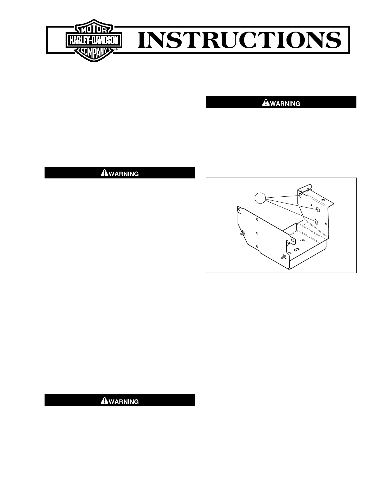
4. See Figure 1. In battery box, identify the location of the
three mounting holes (on left side of panel) for mounting
the cruise control module.
Figure 1. Battery Box (right side view)
5. See Figure 10. Obtain the Cruise Control Module (1) with
cruise cable attached and three Grommets (5) from kit.
Install the grommets on studs of cruise control module
with small diameters outward.
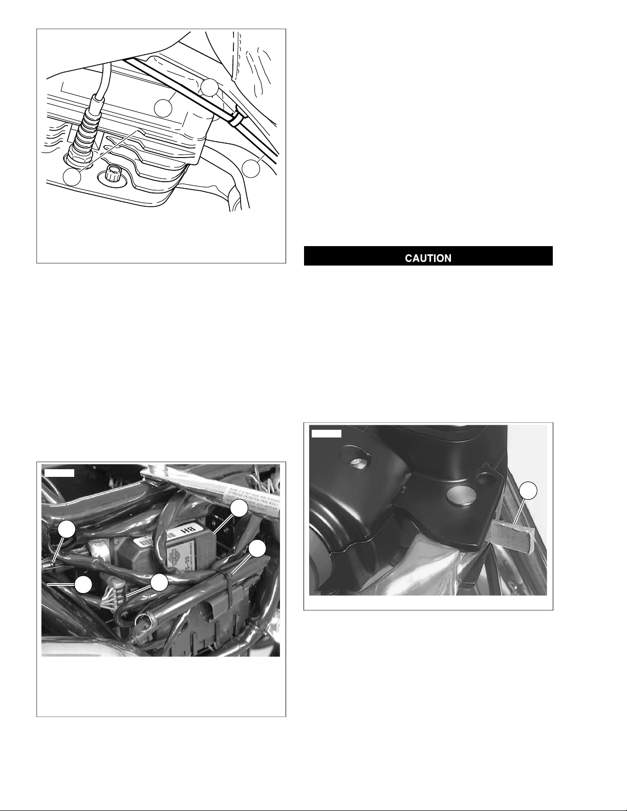
6. See Figure 2.While holding cruise control module in place
near its mounting location, feed the cruise control cable
through the hole in frame crossmember plate and route
under rear spark plug wire staying on inner side of fuel
line components. Carefully cur ve cable toward the right
and continue routing up under the fuel tank and over the
top of the engine stabilizer bracket, then down between
cylinder heads. Leave in place temporarily. See Figure
10. Obtain a harness retainer (4) from kit and secure the
cruise cable to crossmember plate with barb as shown in
Figure 2. On California models, remove the EVAP hose
from cable clip and secure hose with one of the cable ties
(6).
-J04167 1 of 6
Page 2
2
4
3
1
is02721
1. Cruise control cable
5
3
4
2
1
is02722
1
is02723
2. Harness retainer
3. Rear cylinder head
4. From hole in frame crossmember plate
Figure 2. Routing Cruise Cable from Cruise Contr ol Module
to Carburetor or Induction module (left side view)
NOTE
Prior to performing the next step, it may be necessar y to cut
the wire ties securing the main harness to the frame tube
(above mounting area) and temporarily move har ness aside
to allow adequate room for cruise module installation. It may
also be necessary to move the charcoal canister hose to the
side and secure to frame tube with cable tie (8).
7. See Figure 3. Remove the fuse block cover panel by
pulling straight out from mounts and temporarily position
the cover away from the mounting area. Align the cruise
module studs (and grommets) with mounting holes in
battery box and push module firmly into position. Make
sure grommets enter mounting holes in battery box.
8. See Figure 10. Obtain the three flange locknuts (7) and
install to cruise control module studs (inside battery box).
Tighten nuts 9-11 ft-lbs (12.2-15 Nm). Locate the 10-place
connector harness (normally wire tied to frame tube next
to battery box) and cut the tie. Route downward and install
the 10-place connector into cruise module.
9. Reinstall the fuse block cover panel by sliding (side
channels) back onto mounts. See Figure 10. Obtain cable
tie/s (8) from kit. Bundle wire harnesses (mov ed to install
cruise module) along side of cruise module to allow the
side cover to be reinstalled.
10. Return to cruise cable end near carburetor or induction
module. Follow instructions in applicable Service Manual
to connect cruise cable to carburetor or induction module.
See Figure 10. Use new retaining ring (6) from kit when
installing cable end to carburetor/Induction module.
Install New Right Handlebar Control with Harness
Do not remove or install the master cylinder assembly
without first positioning a 5/32-inch (4 mm) thick insert
between the brake lever and lever bracket. Removing or
installing the master cylinder assembly without the insert
in place may result in damage to the rubber boot and
plunger on the front stoplight switch. (00324a)
NOTE
Use the eyelet of an ordinary cable strap if the cardboard insert
is not available.
1. See Figure 4. Place a 5/32 inch cardboard insert between
the brake lever and lever bracket.
1. 5/32 inch cardboard insert
1. Cruise control
2. 10-Place connector
3. Cable tie
4. Cruise control cable
5. To frame crossmember hole
Figure 3. Mount Cruise Control Module
2. Using a T27 TORX® drive head, remove two screws with
flat washers securing the handlebar clamp to the master
cylinder housing. Remove brake lever/master cylinder
assembly and clamp from the handlebar. Use a cable tie
or other means to keep the assembly out of the way.
3. Using T25 T ORX driv e head, remov e the upper and lower
switch housing screws.
4. Remove the friction shoe from the end of the tension
adjuster screw. Save friction shoe for reinstallation.
Figure 4. Install Cardboard Insert
-J04167 2 of 6
Page 3

3
4
5
2
1
is02724
1
3
2
4
is02725
NOTE
The friction shoe is a loose fit and may fall out or become dislodged if the lower switch housing is turned upside down or
shaken.
5. See Figure 5. Remo ve the brass f errules from the notches
on the inboard side of the throttle control grip, then remove
ferrules from the cable end fittings. Save ferrules for reinstallation.
1. Lower cable housing
2. Idle cable insert (gold)
3. Tension adjuster screw
4. Throttle cable insert (silver)
Figure 6. Upper Right Handlebar Switch Housing
9. Trace the right handlebar wiring harness to the 6-place
Molex connector and disconnect connector halves. Note
the existing harness routing and cable ties securing harness to handlebars. Remove and discard the right hand
control and harness assembly.
10. See Figure 10. Obtain the new Right Handlebar Control
1. Throttle cable
2. Idle cable
3. Groove
4. Notch
5. Ferrule
Figure 5. Remove Throttle and Idle Control Cables
NOTE
It is not necessary to remove the throttle control grip.
6. See Figure 6. Pull the crimped inserts at the end of the
throttle and idle control cable housings from the lower
switch housing. For best results, use a rocking motion
while pulling. Place a drop of light oil on the retaining rings,
if necessary. Save inserts for re-installation.
7. Remove the cables from the s witch housing, then separate
the upper and lower switch halves.
8. Follow the instructions in applicable Service Manual and
remove windshield and nacelle.
NOTE
When performing the next Step, the right side Mole x Electrical
Connectors are Black; the left side Mole x Electrical Connectors
are Grey.
and Harness Assembly (2) from kit. Install the ne w harness
6-place connector in same place as connector removed
in Step 9. Locate the unused 3-place connector half (next
to the 6-place) and install the 4-Place connector from the
new harness to the 4-place connector in headlamp
assembly.
11. At new handlebar control assembly, hold the lower switch
housing with concave side facing upward. Install the tension adjuster screw and spring with the friction shoe (saved
from Step 4) so that pin hole is over the point of the Tension adjuster screw. Adjust the tension adjuster two or
three turns to hold assembly in place.
NOTE
The friction shoe is a loose fit and may fall out or become dislodged if the switch housing is turned upside down or shaken.
12. Refer to Figure 6. Push the throttle and idle control cables
into the lower switch housing until they snap into place.
Perform the following:
a. Obtain the crimped inserts removed in Step 6. Note
the different diameter inserts crimped into the end of
the throttle and idle control cable housings.
b. Push the larger diameter insert (silver) on the throttle
cable housing into the larger hole in front of the tension adjuster screw.
c. Push the smaller diameter inser t (gold) on the idle
cable housing into the smaller hole at the rear of the
tension adjuster screw.
NOTE
To aid assembly, place a drop of light oil on the retaining rings
of the crimped inserts. Always replace the retaining rings if
damaged or distorted.
13. Slide the throttle control grip towards motorcycle until it
bottoms against the closed end of the handlebar. Rotate
-J04167 3 of 6
Page 4

the grip so that the ferrule notches are at the top.To pre-
3
4
2
1
is02726
2
3
5
6
4
1
is02727
vent binding, pull the grip back about 1/8 inch (3.2 mm).
14. Refer to Figure 5. Position the new lower switch housing
beneath the throttle control grip. Install the brass ferrules
onto the cables so that the end fittings seat in the ferrule
recess. Seat the ferrules in their respective notches on
the throttle control grip.V erify that the cables are captured
in the grooves molded into the grip.
15. Position the upper s witch housing ov er the handlebar and
lower switch housing.
16. V erify that wire harness conduit runs in the depression at
the bottom of the handlebar. Be sure that the upper s witch
housing harness will not be pinched under the handlebar
when the switch housing screws are tightened.
NOTE
Do not remove the 5/32 inch cardboard insert wedged between
the brake lever and lever bracket. Removal will result in
damage to the rubber boot and plunger of the Front Stoplight
Switch during installation of the master cylinder assembly.
17. Start the upper and lower switch housing screws, but do
not tighten.
18. See Figure 7. Position the brake lever/master cylinder
assembly inboard of the switch housing assembly
engaging the tab on the lower switch housing in the groo ve
at the top of the brake lever bracket.
19. Align the holes in the handlebar clamp with those in the
master cylinder housing and start the two screws (with flat
washers). Position the assembly for rider comfort. Beginning with the top screw , tighten the screws to 60-80 in-lbs
(6-9 Nm) using a T27 TORX® drive head.
21. Remove the cardboard insert between the brake lev er and
lever bracket.
22. See Figure 10. Obtain two harness retainers (4) from kit.
Adjust the harness so it runs under the handlebar and
secure harness conduit to holes in lower side of handlebar
by inserting barbed ends of retainers.
Install New Left Handlebar Control with Harness
NOTE
Prior to performing the next step, cut all cab le ties securing left
control switch harness to handlebars and discard.
1. Trace the left control switch harness wiring to the headlamp area (with nacelle removed) and locate the Grey 8place Molex Connector. Disconnect the handlebar switch
half from the connector.
2. Using a T27 TORX® drive head, remove the two screws
with flat washers securing the handlebar clamp to the
clutch lever bracket. Remove the clutch hand lever
assembly and clamp from the handlebar. Save all hardware for reinstallation.
3. Using a T25 TORX® drive head, remove the upper and
lower switch housing scre ws. Sav e switch housing screws
for reinstallation. Remove the left handlebar control and
harness and discard.
NOTE
It is not necessary to remove the left handlebar grip. Leave
grip in place.
4. See Figure 10. Obtain the new Left Handlebar Control
with Harness (3) from kit.
5. See Figure 8. P osition the left s witch control upper (1) and
lower (2) housings onto the handlebar (3). Be sure that
rib (4) on outboard side of switch housings fits in groove
(5) molded into the grip.
1. Brake lever bracket
2. Groove
3. Tab
4. New switch assembly with cruise Set/Resume
Figure 7. Installing Brake Lever/Master Cylinder Assembl y
to Right Switch Housing Assemblies
When performing the following Step, tighten the lower switch
housing screw first so that any gap between the upper and
lower housings is at the front of the switch.
20. Using a T25 TORX® drive head, tighten the lower then
upper switch housing screws to 35-45 in-lbs (4-5 Nm).
-J04167 4 of 6
NOTE
1. Left switch control upper
2. Left switch control lower
3. Handlebar
4. Rib
5. Groove
6. Wire harness conduit
Figure 8. Installing Left Handlebar Switch Housing
Page 5

6. V erify that the wire harness conduit (6) runs in the groove
3
2
1
4
is02728
at the bottom of the handlebar. Be sure that the upper
switch housing harness will not be pinched under the
handlebar when the switch housing screws are tightened.
7. Start the upper and lower switch housing screws saved
in Step 3, but do not completely tighten at this time.
8. See Figure 9. Position the clutch hand lever assembly
inboard of the switch housing assembly engaging the tab
on the lower switch housing in the groove at the bottom
of the clutch lever bracket. Be sure that harness will not
be pinched when installing handlebar clamp. Harness
should reside in recess between handlebar clamp and
clutch lever bracket.
1. Clutch lever bracket
2. Switch housing assembly
3. Groove
4. Tab
Figure 9. Positioning Clutch Lever Bracket with Left
handlebar Switch Housings
9. Align the holes in the handlebar clamp with those in the
clutch lever bracket and start the two screws (with flat
washers) saved from Step 2. Position the assembly for
rider comfort. Beginning with the top screw, tighten the
screws to 60-80 in-lbs (7-9 Nm) using a T27 T ORX® drive
head.
10. Using a T25 TORX® drive head, tighten the lower and
upper switch housing screws to 35-45 in-lbs (4-5 Nm).
NOTE
Always tighten the lower s witch housing scre w first so that any
gap between the upper and lower housings is at the front of
the switch.
11. Route left hand control harness under handlebar and down
to headlamp area (with nacelle removed). Locate the 8place Molex Connector and connect the 6-place control
harness connector.
12. Locate the unused 3-place Molex Connector and connect
the 3-place control harness connector.
13. See Figure 10. Obtain two wire harness retainers (4) from
kit and secure harness to handlebar in two places by
installing barbs on retainers into holes in handlebar.
14. Follow instructions in applicable Service Manual and install
fairing nacelle and windshield.
15. Follow instructions in Service Manual and install left sad-
dlebag, left side cover and air cleaner assembly.
Connect positive (+) battery cable first. If positive (+) cable
should contact ground with negative (-) cable connected,
the resulting sparks can cause a battery explosion, which
could result in death or serious injury. (00068a)
16. Reconnect battery, positive (+) cable first.
17. Install seat.
After installing seat, pull upward on seat to be sure it is
locked in position. While riding, a loose seat can shift
causing loss of control, which could result in death or
serious injury. (00070b)
Cruise Cable Adjustment and Final Test
1. Perf orm cruise cable adjustment. See "Cable Lash Initial-
ization" in applicable Service Manual.
2. Refer to cruise control section in Owner's Manual for cruise
control operating instructions.
3. Test ride motorcycle and verify cruise control is operating
properly.
-J04167 5 of 6
Page 6

SERVICE PARTS
1
6
2
7
3
8
5
4
A
is02729
Figure 10. Service Parts: FLHR/I and FLHRS/I Cruise Control Kit
Table 1. Service Parts Table
Model FLHRS/I, Kit 77198-07Model FLHR/I, Kit 77197-07
1
ness
170955-04Assembly, cruise control w/har-
ness
Items mentioned in text, but not included in kit:Items mentioned in text, but not included in kit:
Cruise control cableACruise control cableA
Part NumberDescription (Quantity)ItemPart NumberDescription (Quantity)Item
70955-04Assembly, cruise control w/har-
70437-07Assembly, hand control (right)270419-07Assembly, hand control (right)2
70438-07Assembly, hand control (left)370434-07Assembly, hand control (left)3
70345-84Retainer, wire harness (5)470345-84Retainer, wire harness (5)4
11497Grommet (3)511497Grommet (3)5
11193Ring, retaining611193Ring, retaining6
7499Nut, flange locking (3)77499Nut, flange locking (3)7
10065Ties, wire (2)810065Ties, wire (2)8
-J04167 6 of 6
 Loading...