

Page 1
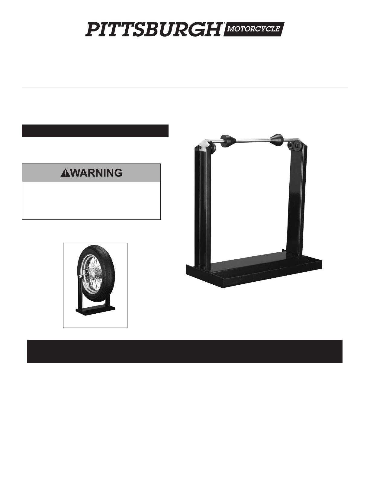
Motorcycle Wheel Balancing Stand
Item 98488
Read this material before using this product.
Failure to do so can result in serious injury.
SAVE THIS MANUAL.
Shown in use with Wheel and
Tire (both not included).
When unpacking, make sure that the product is intact and undamaged.
If any parts are missing or broken, please call 1-800-444-3353 as soon as possible.
Visit our website at: http://www.harborfreight.com
Copyright© 2008 by Harbor Freight Tools®. All rights reserved. No portion of this manual or any artwork contained herein may be reproduced in any shape
or form without the express written consent of Harbor Freight Tools. Diagrams within this manual may not be drawn proportionally. Due to continuing
improvements, actual product may differ slightly from the product described herein. Tools required for assembly and service may not be included.
Manual Revised 11e
Page 2
Specications
Dual purpose stand to balance mounted tires.
Accepts up to 13-7/8” W tires, 12-1/2” wide
hubs and 1.59”/15 mm to 1.46”/37 mm axles.
The following Adapters (not included) are
available from Harbor Freight Tools:
Balance Adapter to
SKU 98489
SKU 98490
SKU 98493
SKU 65079
be used for Ducati
® Motorcycles
Balance Adapter to
be used for BMW®
Motorcycles
Balance Adapter to
be used for Harley
Davidson® Motorcycles
Balancer adapter to
be used for Honda®
motorcycles.
Use Precautions
1. This product is not a toy. Do not allow
children to play with or near this item.
2. Use for intended purpose only.
3. Inspect before use; do not use if
parts are loose or damaged.
4. Maintain product labels and nameplates.
These carry important safety information.
If unreadable or missing, contact
Harbor Freight Tools for a replacement.
Assembly Instructions
Read the ENTIRE IMPORTANT
SAFETY INFORMATION section at the
beginning of this document including
all text under subheadings therein
before set up or use of this product.
Below are accessories needed for wheel aligning.
(All not included)
SKU 623 1” Travel Machinist’s
Dial Indicator
SKU 33675 1’’ Dial Indicator
SKU 5645 Multipositional
Magnetic Base with
Fine Adjustment
IMPORTANT SAFETY
INFORMATION
Assembly Precautions
1. Assemble only according
to these instructions.
Improper assembly can create hazards.
2. Wear ANSI-approved safety goggles and
heavy-duty work gloves during assembly.
3. Keep assembly area clean and well lit.
4. Keep bystanders out of the
area during assembly.
5. Do not assemble when tired or when under
the inuence of drugs or medication.
Assembly
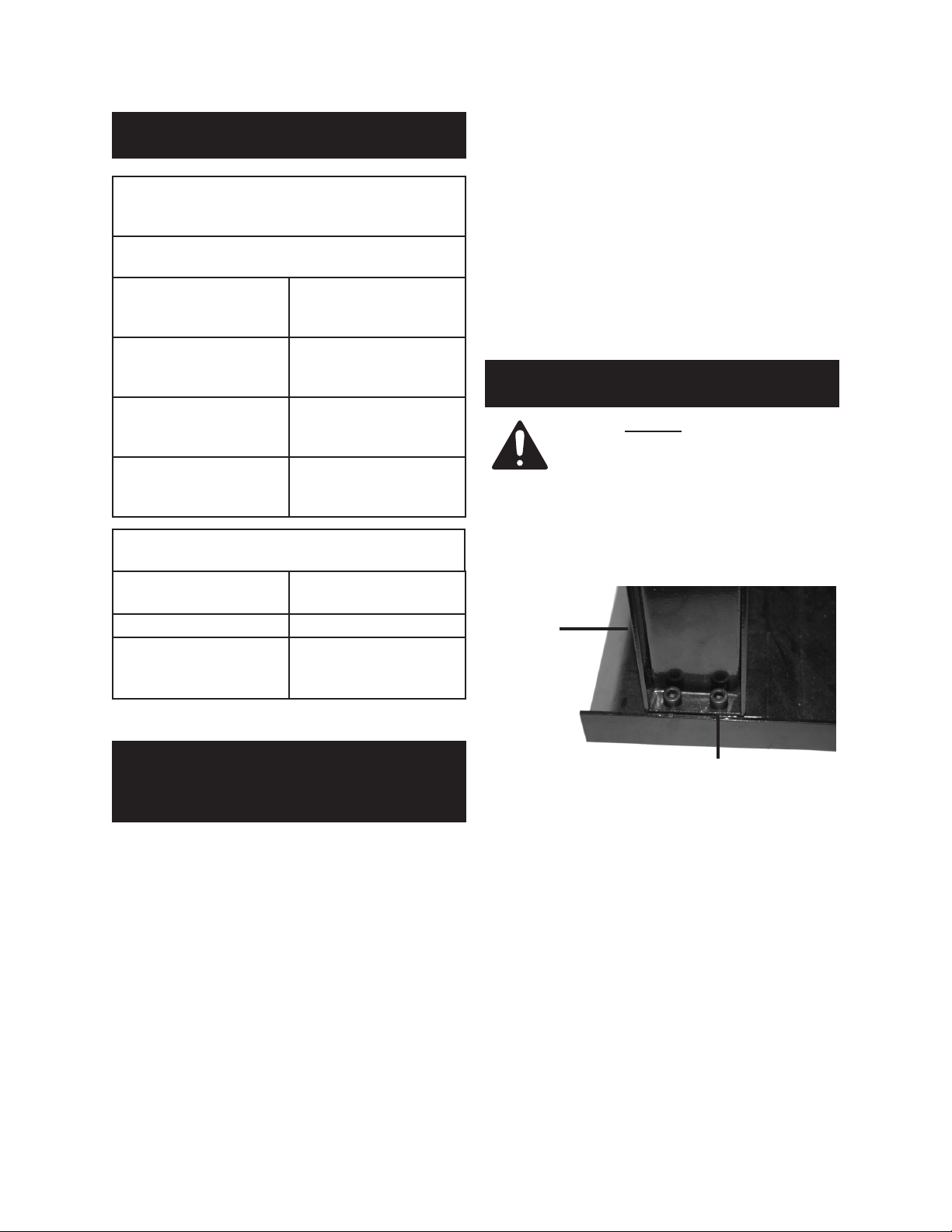
Figure 1
Side
Frame (2)
Socket Head Screw (9)
1.
Attach each Side Frame (2) to the Base (1):
With the face of the Side Frame (2) facing
inward, insert two Socket Head Screw
(9) down through the Side Frame and
through the Base (1). Secure in place
with two Lock Nuts (10)-see Figure 1.
REV 08f
SKU 98488 For technical questions, please call 1-800-444-3353. Page 2
Page 3

Figure 2
Roller (6)
Axle (5)
2.
Set the Axle (5) onto the Rollers (6)
as shown in Figure 2.
Operating Instructions
1. Prior to use check to make
certain that the Axle is straight,
without any bends or damage.
2. Back off both Socket Set Screw (12) and
slide off one of the Centering Cones (4) from
Axle (5). Support the wheel of the motorcycle
in an upright position and slide the Axle (5)
through the wheel hub and replace the
Cone. Center the wheel on the Axle and
slide both Cones securely against the hub.
Tighten the Socket Cap Screws (12).
3. Lift the wheel and position the Axle over
the Rollers (6). Gently spin the wheel. The
heavier side would roll to the bottom. With
a chalk mark the tire at the upper most
location (across from the heavy side).
4. Lift the wheel assembly from the
stand and place on the oor. Attach a
balancing weight (not supplied) to the
inner edge of the rim and reposition the
wheel assembly over the Rollers (6).
NOTE: Use lightest possible weights.
With try and error, you should be able to
establish approximate required weights.
5. Gently spin the tire. Repeat steps 3 and 4
placing balancing weights on
alternative sides of the tire rim.
6. Continue to counter balance the wheel until
it spins evenly and does not repeatedly
stop at any specic point of its rotation.
7. Once the wheel is balanced, remove the
assembly and place on the oor, back off
one Socket Set Screw (12) and remove
the Centering Cone (4). Remove the Axle,
replace the Cone and tighten the screw.
Place the axle on the rollers.
Maintenance
1. Before each use, inspect the general
condition of the Balancing Stand.
Check for loose screws, misalignment
or binding of moving parts, cracked or
broken parts, and any other condition
that may affect its safe operation.
2. Periodically lubricate contact points
and Rollers with grease.
Replacing Rollers
1. Rollers (6) and Bearings (7) can be replaced
by removing Socket Head Screw (11) and
pulling Rollers off of the Balancing Stand.
2. Replace with new Rollers (6) and
Bearings (7) and secure with Socket
Set Screw (11). See Figure 2.
3. When not in use, store in a safe
location away from children.
PLEASE READ THE
FOLLOWING CAREFULLY
THE MANUFACTURER AND/OR DISTRIBUTOR
HAS PROVIDED THE PARTS LIST AND
ASSEMBLY DIAGRAM IN THIS DOCUMENT AS
A REFERENCE TOOL ONLY. NEITHER THE
MANUFACTURER OR DISTRIBUTOR MAKES
ANY REPRESENTATION OR WARRANTY OF
ANY KIND TO THE BUYER THAT HE OR SHE
IS QUALIFIED TO MAKE ANY REPAIRS TO THE
PRODUCT, OR THAT HE OR SHE IS QUALIFIED
TO REPLACE ANY PARTS OF THE PRODUCT.
IN FACT, THE MANUFACTURER AND/OR
DISTRIBUTOR EXPRESSLY STATES THAT
ALL REPAIRS AND PARTS REPLACEMENTS
SHOULD BE UNDERTAKEN BY CERTIFIED
AND LICENSED TECHNICIANS, AND NOT
BY THE BUYER. THE BUYER ASSUMES ALL
RISK AND LIABILITY ARISING OUT OF HIS OR
HER REPAIRS TO THE ORIGINAL PRODUCT
OR REPLACEMENT PARTS THERETO, OR
ARISING OUT OF HIS OR HER INSTALLATION
OF REPLACEMENT PARTS THERETO.
SKU 98488 For technical questions, please call 1-800-444-3353. Page 3
Page 4

Parts List and Assembly Diagram
Part Description Qty.
1 Base 1
2 Side Frame 2
3 Mounting Plate 2
4 Centering Cone 2
5 Axle 1
6 Roller 4
7 Bearing 4
8 Sleeve 4
9 Socket Head Screw M8 x 20 4
10 Lock Nut M8 4
11 Socket Set Screw M8 x 25 4
12 Socket Head Screw M6 x 15 2
Note: Some parts are listed and
shown for illustration purposes only,
and are not available individually
as replacement parts.
Limited 90 Day Warranty
Harbor Freight Tools Co. makes every effort to
assure that its products meet high quality and
durability standards, and warrants to the original
purchaser that this product is free from defects in
materials and workmanship for the period of 90
days from the date of purchase. This warranty does
not apply to damage due directly or indirectly, to
misuse, abuse, negligence or accidents, repairs or
alterations outside our facilities, criminal activity,
improper installation, normal wear and tear, or
to lack of maintenance. We shall in no event be
liable for death, injuries to persons or property, or
for incidental, contingent, special or consequential
damages arising from the use of our product.
Some states do not allow the exclusion or limitation
of incidental or consequential damages, so the
above limitation of exclusion may not apply to
you. THIS WARRANTY IS EXPRESSLY IN LIEU
OF ALL OTHER WARRANTIES, EXPRESS
OR IMPLIED, INCLUDING THE WARRANTIES
OF MERCHANTABILITY AND FITNESS.
To take advantage of this warranty, the product
or part must be returned to us with transportation
charges prepaid. Proof of purchase date and an
explanation of the complaint must accompany the
merchandise. If our inspection veries the defect,
we will either repair or replace the product at our
election or we may elect to refund the purchase
price if we cannot readily and quickly provide
you with a replacement. We will return repaired
products at our expense, but if we determine
there is no defect, or that the defect resulted from
causes not within the scope of our warranty, then
you must bear the cost of returning the product.
This warranty gives you specic legal
rights and you may also have other
rights which vary from state to state.
3491 Mission Oaks Blvd. • PO Box 6009
Camarillo, CA 93011 • (800) 444-3353
SKU 98488 For technical questions, please call 1-800-444-3353. Page 4
 Loading...