

Page 1
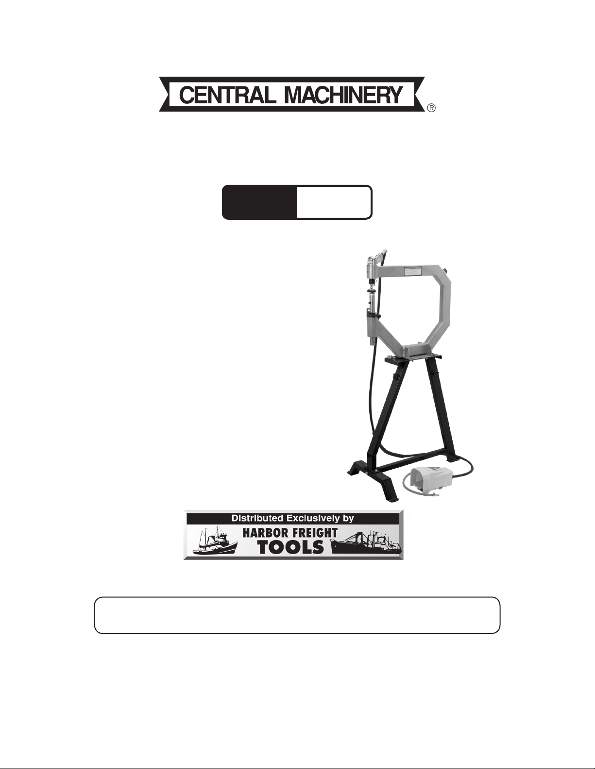
PLANISHING HAMMER STAND
Model
96300
®
FOR USE WITH SKU 94847 PLANISHING HAMMER
ASSEMBLY AND OPERATION INSTRUCTIONS
Please Note: Planishing Hammer not included with
Stand.
Due to continuing improvements, actual product may
differ slightly from the product described herein.
3491 Mission Oaks Blvd., Camarillo, CA 93011
Visit our website at: http://www.harborfreight.com
TO PREVENT SERIOUS INJURY, READ AND UNDERSTAND
ALL WARNINGS AND INSTRUCTIONS BEFORE USE.
Copyright© 2007 by Harbor Freight Tools®. All rights reserved. No portion of this
manual or any artwork contained herein may be reproduced in any shape or form
without the express written consent of Harbor Freight Tools.
For technical questions or replacement parts, please call 1-800-444-3353.
Cover Revised 07f
Page 2
SPECIFICATIONS
Use only with SKU 94847 Planishing Hammer
Materials Formed steel sheets with a powder-
coated finish, zinc plated hardware
Mounting Plate Dimension
Top Plate Mounting Holes/
Slots Dimension
Base Mounting Hole Diameter
Hardware Thread Type
12-3/4” L x 5-1/2” W x 0.151” T
3/4” diameter, four holes
1” L x 7/16” W, four slots
7/16” diameter, three holes
M8 x 1.25
Save This Manual
You will need this manual for the safety warnings and precautions, assembly, operating, inspection, maintenance and cleaning procedures, parts list and assembly diagram.
Keep your invoice with this manual. Keep this manual and invoice in a safe and dry place
for future reference.
GENERAL SAFETY RULES
1.
2.
3.
4.
5.
6.
WARNING!
READ AND UNDERSTAND ALL INSTRUCTIONS
Failure to follow all instructions listed below may result in
serious injury.
SAVE THESE INSTRUCTIONS
Keep your work area clean and well lit. Cluttered benches and dark areas invite
accidents.
Keep bystanders, children, and visitors away. Distractions can cause you to lose
control. Keep children out of the work area.
Stay alert. Watch what you are doing and use common sense during assembly
and use of this product.
During assembly dress properly. Do not wear loose clothing or jewelry. Con-
tain long hair.
Do not overreach. Keep proper footing and balance at all times.
Use safety equipment during assembly. Always wear eye protection. Always
wear ANSI-approved safety goggles when assembling and using the Planishing
Hammer Stand.
For technical questions, please call 1-800-444-3353.
REV 07j
Page 2SKU 96300
Page 3

7.
Do not force the product. Use the correct product for your application. The
correct product will do the job better and safer at the rate for which it is designed. Do
not force the product and do not use it for a purpose for which it is not intended.
8.
9.
10.
11.
12.
13.
14.
15.
Store an idle Planishing Hammer Stand out of reach of children and other
untrained persons.
Maintain this product with care.
Use only accessories that are recommended by the manufacturer for your
model. Accessories that may be suitable for one product may become hazardous
when used on another product.
Maintain labels and nameplates on the Planishing Hammer Stand. These carry
important information. If unreadable or missing, contact Harbor Freight Tools for a
replacement.
Maintain a safe working environment. Make sure there is adequate surrounding
workspace. Do not use this product in a damp or wet location.
Do not use to support any items other than SKU 94847, Planishing Hammer.
Use on a flat, level surface capable of supporting the Planishing Hammer
Stand, the Planishing Hammer, the metal being worked on, and the vibration
of the planishing process.
Do not use this Planishing Hammer Stand as a stepping stool or ladder. Never
sit, stand, or climb on this Planishing Hammer Stand. Never allow children to play
on or climb on this Stand.
16.
Only fill the Planishing Hammer Stand with sand.
ASSEMBLY INSTRUCTIONS
Note: For additional information regarding the parts listed in the following pages, refer to
the Assembly Diagram on page 7.
1.
Connect Main Support (3) to Table Support (2). Insert two Bolts (6) with Washers
(10) down through the Table Support (2) and Main Support (3). Slide on two more
Washers (10), Spring Washers (9) and thread on the Nuts (7).
For technical questions, please call 1-800-444-3353.
Page 3SKU 96300
Page 4

Table Support (2)
Figure 1
Bolts (4), Washers (10)
Leg (1)
Spring Washers (9) and
Nuts (7) (not visible)
2.
3.
4.
5.
Attach Table Support (2) to Leg (1). Insert two Bolts (4) with Washers (10) down
through the Table Support (2) and down through the Leg (1). Slide on two more
Washers (10), Spring Washers (9) and thread on the Nuts (7) - see Figure 1.
Secure Cross Bar (8) to both the Main Support (3) and Leg (1). Slide Spring Washer
(9) and Washer (10) onto Bolt (5). Thread in through Main Support (3) and into
Cross Bar (8). From the opposite side, slide Spring Washer (9) and Washer (10)
onto second Bolt (5) and thread into Leg (1) and into Cross Bar (8).
Tighten all hardware.
Check the Planishing Hammer Stand to make certain that it sits evenly, fully resting
on the ground. Make certain that all hardware is fully tightened.
Figure 2
Main Support (3)
Plug (11)
6.
7.
Unscrew and remove both Plugs (11)-see Figure 2-and fill the Stand with sand to
reduce noise when using the Planishing Hammer. Only use sand to fill the Stand.
Do not use any other material or any liquid to fill the Stand. Screw the Plugs
back onto the Stand.
Place the Planishing Hammer on top of the Stand and align the mounting holes of
both Stand and Planishing Hammer. Position the operating portion of the planishing
hammer above the Leg (1) of the stand as shown on the cover picture.
REV 07f
For technical questions, please call 1-800-444-3353.
Page 4SKU 96300
Page 5

8.
Secure Planishing Hammer to the Planishing Hammer Stand by sliding a grade-5
bolt (not included) of adequate length through a flat washer (not included), then
through the base hole of the Planishing Hammer, and then through the mounting
plate of the Stand. Slide another flat washer (not included) over the bolt. Attach a
self-locking nut (not included). Repeat this operation for the remaining mounting
holes. Then tighten all the nuts.
9.
The Planishing Hammer Stand has three 7/16” holes for mounting the Stand to your
work surface (hardware not included). Use on a flat, level surface capable of
supporting the Planishing Hammer Stand, the Planishing Hammer, the metal
being worked on, and the vibration of the planishing process.
INSPECTION, MAINTENANCE, AND CLEANING
1.
2.
Clean the Planishing Hammer Stand with a damp cloth. Do not use abrasives,
harsh chemicals or detergents as these will scratch and damage the Planishing
Hammer Stand.
BEFORE EACH USE, inspect the general condition of the Planishing Hammer
Stand. Check for loose fasteners, cracked or broken parts and any other condition
that may affect its safe operation. Always make sure the Planer is firmly attached
to the Stand. Do not use damaged equipment.
PARTS LIST
Part Description Q’ty
1 Leg 1
2 Table Support 1
3 Main Support 1
4 Bolt M 8 x 50mm 2
5 Bolt M8 x 75mm 2
6 Bolt M8 x 20mm 2
Part Description Q’ty
7 Nut M8 4
8 Cross Bar 1
9 Spring Washer 6
10 Flat Washer 10
11 Plug 2
PLEASE READ THE FOLLOWING CAREFULLY
THE MANUFACTURER AND/OR DISTRIBUTOR HAS PROVIDED THE PARTS LIST AND ASSEMBLY DIAGRAM IN THIS
MANUAL AS A REFERENCE TOOL ONLY. NEITHER THE MANUFACTURER OR DISTRIBUTOR MAKES ANY REPRESENTATION OR WARRANTY OF ANY KIND TO THE BUYER THAT HE OR SHE IS QUALIFIED TO MAKE ANY REPAIRS TO THE
PRODUCT, OR THAT HE OR SHE IS QUALIFIED TO REPLACE ANY PARTS OF THE PRODUCT. IN FACT, THE MANUFACTURER AND/OR DISTRIBUTOR EXPRESSLY STATES THAT ALL REPAIRS AND PARTS REPLACEMENTS SHOULD BE
UNDERTAKEN BY CERTIFIED AND LICENSED TECHNICIANS, AND NOT BY THE BUYER. THE BUYER ASSUMES ALL
RISK AND LIABILITY ARISING OUT OF HIS OR HER REPAIRS TO THE ORIGINAL PRODUCT OR REPLACEMENT PARTS
THERETO, OR ARISING OUT OF HIS OR HER INSTALLATION OF REPLACEMENT PARTS THERETO.
For technical questions, please call 1-800-444-3353.
Page 5SKU 96300
Page 6

ASSEMBLY AND PARTS DIAGRAM
11
11
For technical questions, please call 1-800-444-3353.
Page 6SKU 96300
Page 7

LIMITED 1 YEAR WARRANTY
Harbor Freight Tools Co. makes every effort to assure that its products meet high
quality and durability standards, and warrants to the original purchaser that this product is
free from defects in materials and workmanship for the period of one year from the date of
purchase (90 days if used by a professional contractor or if used as rental equipment). This
warranty does not apply to damage due directly or indirectly, to misuse, abuse, negligence
or accidents, repairs or alterations outside our facilities, normal wear and tear, or to lack
of maintenance. We shall in no event be liable for death, injuries to persons or property, or
for incidental, contingent, special or consequential damages arising from the use of our
product. Some states do not allow the exclusion or limitation of incidental or consequential
damages, so the above limitation of exclusion may not apply to you. THIS WARRANTY IS
EXPRESSLY IN LIEU OF ALL OTHER WARRANTIES, EXPRESS OR IMPLIED, INCLUDING THE WARRANTIES OF MERCHANTABILITY AND FITNESS.
To take advantage of this warranty, the product or part must be returned to us with
transportation charges prepaid. Proof of purchase date and an explanation of the complaint must accompany the merchandise. If our inspection verifies the defect, we will either
repair or replace the product at our election or we may elect to refund the purchase price
if we cannot readily and quickly provide you with a replacement. We will return repaired
products at our expense, but if we determine there is no defect, or that the defect resulted
from causes not within the scope of our warranty, then you must bear the cost of returning
the product.
This warranty gives you specific legal rights and you may also have other rights
which vary from state to state.
3491 Mission Oaks Blvd. • PO Box 6009 • Camarillo, CA 93011 • (800) 444-3353
For technical questions, please call 1-800-444-3353.
Page 7SKU 96300
 Loading...