

Harbor Freight Tools 96188 Product manual
50 TON SHOP PRESS
Model
96188
ASSEMBLY AND OPERATION INSTRUCTIONS
REV 11h
Diagrams within this manual may not be drawn proportionally.
Due to continuing improvements, actual product may differ slightly from the product described herein.
Distributed exclusively by Harbor Freight Tools®.
3491 Mission Oaks Blvd., Camarillo, CA 93011
Visit our website at: http://www.harborfreight.com
Read this material before using this product.
Failure to do so can result in serious injury.
SAVE THIS MANUAL.
Copyright© 2007 by Harbor Freight Tools®. All rights reserved. No portion of this
manual or any artwork contained herein may be reproduced in any shape or form
without the express written consent of Harbor Freight Tools.
For technical questions or replacement parts, please call 1-800-444-3353.

SPECIFICATIONS
Maximum Capacity 50 Tons
Compressed Air PSI Range 70 to 150 PSI
Overall Dimensions 67-1/2” H x 56-1/2” W x 31-1/2” D
Rail Width 9-1/4”
Pressure Gauge Markings 0-70 Tons
Pressure Gauge Thread 1/2” NPT
Piston Rod Diameter 2-1/4”
Piston Rod Travel 6-5/8”
Air Inlet Connector Size 1/4” - 18 NPT
Mounting Holes 4 at 3/4” Diameter
Weight 645 Pounds
SAVE THIS MANUAL
You will need this manual for the safety warnings and precautions, assembly,
operating, inspection, maintenance, and cleaning procedures. Keep your invoice
with this manual. Write the invoice number on the inside of the front cover. Keep
this manual and invoice in a safe and dry place for future reference.
GENERAL SAFETY WARNINGS
Keep work area clean and dry. 1. Cluttered, dark or wet work areas invite injuries.
Keep children and bystanders away from work area. 2. Do not allow children or
untrained individuals to handle this product.
Store idle equipment. 3. When not in use, tools and equipment should be stored in
a dry location to inhibit rust. Always lock up tools and equipment and keep out of
reach of children.
Do not use a power tool while tired or under the influence of drugs, alcohol, 4.
or medication. A moment of inattention while operating power tools may result in
serious personal injury. Read warning labels on prescriptions to determine if your
judgment or reflexes are impaired while taking drugs. If there is any doubt, do not
use this product.
Dress with safety in mind. 5. Wear ANSI approved safety impact eyeglasses and
heavy-duty work gloves when using this product. Non-skid footwear or safety shoes
should be used when working with this product. Do not wear loose clothing or jewelry as they can become caught in moving parts. Wear a protective hair covering
to prevent long hair from becoming caught in moving parts.
Industrial applications must follow OSHA requirements.6.
REV 07j
For technical questions, please call 1-800-444-3353.
Page 2SKU 96188

Do not overreach. 7. Keep proper footing and balance at all times. Proper footing
and balance enable better control in unexpected situations.
Stay alert. 8. Watch what you are doing at all times. Use common sense. Do not
use this product when you are tired or distracted from the job at hand.
Check for misalignment or binding of moving parts, breakage of parts, and any 9.
other condition that may affect the tool’s operation. If damaged, have the tool
serviced before using. Many accidents are caused by poorly maintained tools.
Maintain this product with care. 10. Keep this tool clean and dry for better and safer
performance.
Maintenance: For your safety, service and maintenance should be performed 11.
regularly by a qualified technician.
Do not force the tool. 12. Use the correct tool for your application. The correct tool
will do the job better and safer at the rate for which it is designed. Do not force the
tool and do not use the tool for a purpose for which it is not intended.
SPECIFIC PRODUCT WARNINGS
Warning: if you detect anything that may indicate imminent structural failure 1.
to the Shop Press, discontinue use immediately. Disconnect the Shop Press
from its compressed air supply source and have the problem corrected before further use.
Do not install this equipment on any asphalt or wood surface. 2. Make sure the
Shop Press is firmly secured to a dry, oil/grease free, flat, level concrete surface
capable of supporting the combined weight of the Shop Press, the workpiece being
pressed, and any additional tools and equipment. Do not install the Shop Press on
expansion seams or on cracked, defective concrete.
Maintain a safe work environment. 3. Do not use the Shop Press near wet areas. Do
not expose this tool to rain. Make sure there is adequate surrounding work space.
Use this tool in a well-ventilated area. Do not operate this tool in the presence of
flammable liquids, gases, or dust.
Read and understand all instructions and safety precautions in the manufactur-4.
er’s manual for the workpiece you are pressing. Always use the manufacturer’s
recommended pressing points, minimum/maximum pressing force required, etc. for
the workpiece you are pressing.
Never exceed the maximum PSI and pressing capacity. 5. This Shop Press will do
the work better and safer at the speed and capacity for which it is designed. Do not
exceed the maximum 150 psi compressed air supply or the 50 ton press capacity.
For technical questions, please call 1-800-444-3353.
Page 3SKU 96188

Remove adjusting keys or wrenches before turning the Shop Press on. 6. A
wrench or a key that is left attached to a rotating part of the power tool may result
in personal injury.
Avoid unintentional starting. 7. Make sure you are prepared to begin work before
squeezing the handle on the Air Valve (40A).
Avoid off-center loads. 8. If the Pressure Head Assembly (22A) seems unusually
hard to press, immediately stop the operation. Disconnect the Shop Press from its
compressed air supply source, and adjust the workpiece to eliminate or diminish
an off-center load. Do not operate the Shop Press if the workpiece tilts or binds
during the down movement of the Pressure Head Assembly.
Prior to lowering the Pressure Head Assembly (22A) remove tool trays, stands, 9.
and all other tools and equipment from the Press Table (6A).
Always keep hands, fingers, and feet away from the Pressure Head Assembly 10.
(22A) and Press Table (6A) during the pressing process.
Never attempt to remove a workpiece stuck in the moving parts of the Shop 11.
Press while it is connected to the compressed air supply source.
The workpiece must be supported and controlled at all times during opera-12.
tion. Use a roller stand (not provided) with a larger workpiece. Whenever possible,
secure the workpiece with clamps (not provided).
Once contact between the pressure head and workpiece has been made, 13.
step away as far as possible and continue to slowly apply pressure until the
procedure is complete.
Never leave a compressed workpiece unattended. 14. When a workpiece is com-
pressed, there is a large degree of force that has been stored in the workpiece, this
must be controlled until the Pressure Head Assembly is released.
Keep the Shop Press properly filled with hydraulic oil. 15. For instructions, see
“Inspection, Maintenance, and Cleaning” section in this manual.
Before performing service or maintenance release the load from the Shop 16.
Press and disconnect it from the compressed air supply source.
WARNING: This product contains or, when used, produces a chemical known 17.
to the State of California to cause cancer and birth defects or other reproductive harm. (California Health & Safety Code § 25249.5, et seq.)
Warning: The warnings, cautions, and instructions discussed in this instruction manual cannot cover all possible conditions and situations that may occur. It
must be understood by the operator that common sense and caution are factors
which cannot be built into this product, but must be supplied by the operator.
For technical questions, please call 1-800-444-3353.
Page 4SKU 96188
UNPACKING
When unpacking, check to make sure all parts listed in the Parts List are included. If
any parts are missing or broken, please call Harbor Freight Tools at the number shown
on the cover of this manual as soon as possible.
ASSEMBLY INSTRUCTIONS
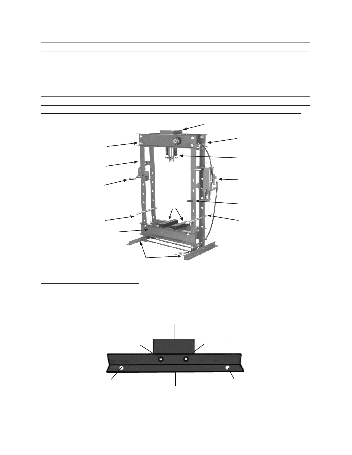
For additional references to the parts listed below, refer to Assembly Diagrams.
PRESSURE GAUGE (17A)
RIGHT UPRIGHT
TOP SHAFT (30A)
LEFT UPRIGHT
(8A)
HOIST (29A)
ARBOR
PLATE
(23A)
(8A)
PRESSURE HEAD
ASSEMBLY
(1B THRU 22B)
PUMP Assembly.
(1C THRU 35C)
JACK HANDLE (19C)
SUPPORT PIN (9A)
Press Table
(6A)
BASE SUPPORT
To Attach The Base Supports:
Secure the right and left Base Supports (5A) to the bottoms of the right and left •
Uprights (8A), using two Screws (2A), two Spring Washers (4A), and two Nuts
(3A) for each Base Support. Seek help to set upright. (See Figure A & B)
SCREW (2A)
SPRING WASHER (4A)
NUT (3A)
FLOOR SURFACE
MOUNTING HOLE
(5A)
UPRIGHT (8A)
BASE
SUPPORT
(5A)
SUPPORT PIN (9A)
FIGURE A
SCREW (2A)
SPRING WASHER (4A)
NUT (3A)
FLOOR SURFACE
MOUNTING HOLE
FIGURE B
For technical questions, please call 1-800-444-3353.
REV 07j
Page 5SKU 96188
 Loading...