

Page 1
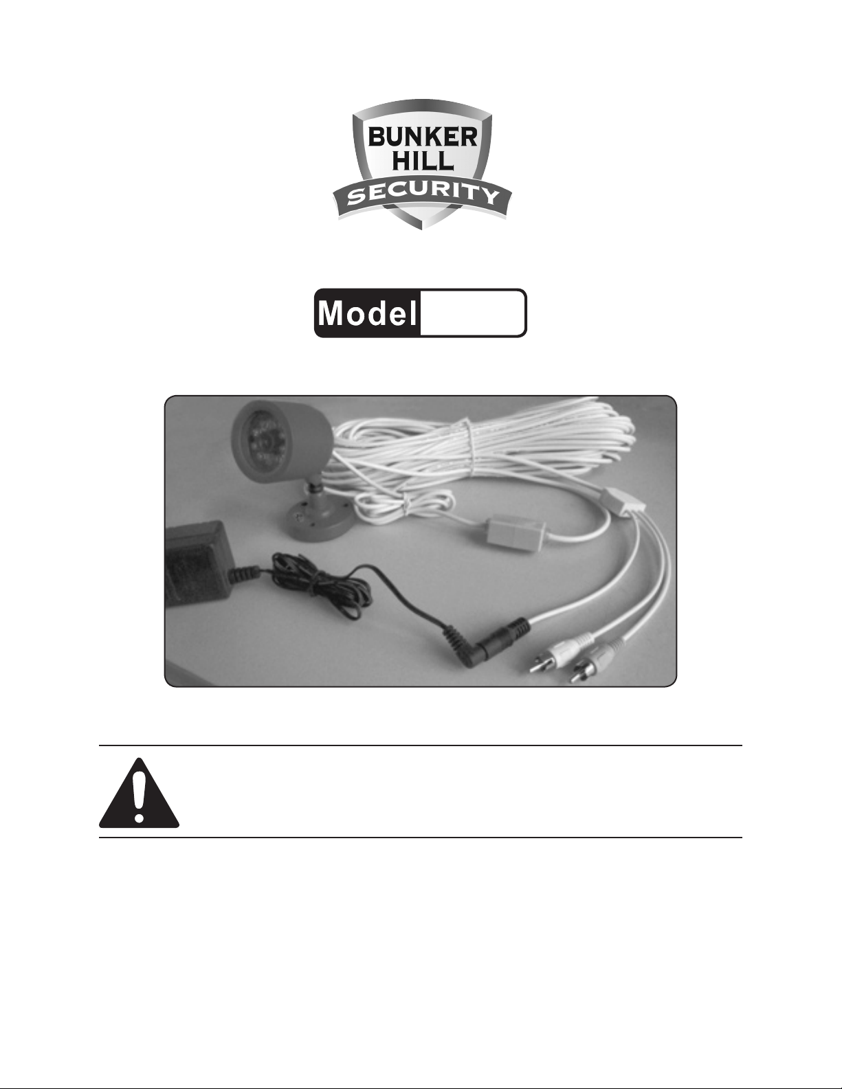
COLOR SECURITY CAMERA
95914
SET UP AND OPERATING INSTRUCTIONS
Visit our website at: http://www.harborfreight.com
Read this material before using this product.
Failure to do so can result in serious injury.
SAVE THIS MANUAL.
Copyright© 2007 by Harbor Freight Tools®. All rights reserved. No portion of this manual or any artwork
contained herein may be reproduced in any shape or form without the express written consent of
Harbor Freight Tools. Diagrams within this manual may not be drawn proportionally. Due to continuing
improvements, actual product may differ slightly from the product described herein. Tools required for
assembly and service may not be included.
For technical questions or replacement parts, please call 1-800-444-3353.
Manual Revised 10a
Page 2
SAVE THIS MANUAL
Keep this manual for the safety
warnings and precautions, assembly,
operating, inspection, maintenance and
cleaning procedures. Write the product’s
serial number in the back of the manual
near the assembly diagram (or month
and year of purchase if product has no
number). Keep this manual and the
receipt in a safe and dry place for future
reference.
not avoided, could result in
minor or moderate injury.
NOTICE is used to
address practices
not related to personal injury.
CAUTION, without
the safety alert
symbol, is used to address
practices not related to
personal injury.
General Safety Warnings
IMPORTANT SAFETY
INFORMATION
In this manual, on the labeling,
and all other information
provided with this product:
This is the safety alert
symbol. It is used to alert
you to potential personal
injury hazards. Obey all
safety messages that
follow this symbol to avoid
possible injury or death.
DANGER indicates
a hazardous
situation which, if not
avoided, will result in death or
serious injury.
WARNING
indicates a
hazardous situation which, if
not avoided, could result in
death or serious injury.
CAUTION, used
with the safety
alert symbol, indicates a
hazardous situation which, if
WARNING Read all safety
warnings and instructions.
Failure to follow the warnings and
instructions may result in electric
shock, re and/or serious injury.
Save all warnings and
instructions for future reference.
Work area safety1.
Keep work area clean and well a.
lit. Cluttered or dark areas invite
accidents.
Do not operate power tools in b.
explosive atmospheres, such
as in the presence of ammable
liquids, gases or dust. Power tools
create sparks which may ignite the
dust or fumes.
Keep children and bystanders c.
away while operating a power
tool. Distractions can cause you to
lose control.
WORK AREA
Keep your work area clean and 1.
well lit. Cluttered benches and dark
areas invite accidents.
Do not operate electrically 2.
powered products in explosive
Page 2For technical questions, please call 1-800-444-3353.SKU 95914
Page 3

atmospheres, such as in the
presence of ammable liquids,
gases, or dust. Electrically powered
products create sparks which may
ignite the dust or fumes.
ELECTRICAL SAFETY
times. Proper footing and balance
enables better control in unexpected
situations.
Wear ANSI-approved safety 3.
goggles during installation and
maintenance.
Avoid body contact with grounded 1.
surfaces such as pipes, radiators,
ranges, and refrigerators. There is
an increased risk of electric shock if
your body is grounded.
Do not expose the AC/DC Adapter 2.
of this product to rain or wet
conditions. Water entering the AC/
DC Adapter will increase the risk of
electric shock.
Do not abuse the AC/DC Adapter 3.
Power Cord. Never use the Power
Cord to carry the Adapter or pull
the Plug from an outlet. Keep the
Power Cord away from heat, oil,
sharp edges, or moving parts.
Replace damaged Power Cords
immediately. Damaged Power
Cords increase the risk of electric
shock.
TOOL USE AND CARE
Do not force this product. Use 1.
the correct product for your
application. The correct product
will do the job better and safer at the
rate for which it is designed. Do not
force the product and do not use this
product for a purpose for which it is
not intended.
Disconnect the AC/DC Adapter 2.
from the power source before
making any adjustments, changing
accessories, or storing this
product. Such preventive safety
measures reduce the risk of starting
the product accidentally. Always
unplug the AC/DC Adapter from its
electrical outlet before performing
any inspection, maintenance, or
cleaning procedures.
PERSONAL SAFETY
Stay alert. Watch what you are 1.
doing, and use common sense
when operating electrically
powered products. Do not use
electrically powered products
while tired or under the inuence
of drugs, alcohol, or medication. A
moment of inattention while operating
these products may result in serious
personal injury.
Do not overreach when 2.
assembling this product. Keep
proper footing and balance at all
Store idle electrically powered 3.
products out of reach of children
and other untrained persons.
Electrically powered products are
dangerous in the hands of untrained
users.
Maintain this product with care. 4.
Keep this product clean. Properly
maintained products are less likely to
malfunction and are easier to control.
Do not use a damaged product. Tag
damaged products “Do not use” until
repaired.
Page 3For technical questions, please call 1-800-444-3353.SKU 95914
Page 4

Check for misalignment or binding 5.
of moving parts, breakage of
parts, and any other condition
that may affect this product’s
operation. If damaged, have the
product serviced before using.
Many accidents are caused by poorly
maintained products.
Use only accessories that are 6.
recommended by the manufacturer
for your model. Accessories that
may be suitable for one product may
become hazardous when used on
another product.
SERVICE
Product service must be 1.
performed only by qualied repair
personnel. Service or maintenance
performed by unqualied personnel
could result in a risk of injury.
When servicing a product, use 2.
only identical replacement
parts. Follow instructions in the
“Inspection, Maintenance, And
Cleaning” section of this manual.
Use of unauthorized parts or failure
to follow maintenance instructions
may create a risk of electric shock or
injury.
SPECIFIC SAFETY RULES
Maintain labels and nameplates 1.
on the this product. These carry
important information. If unreadable
or missing, contact Harbor Freight
Tools for a replacement.
Maintain a safe product use 2.
environment. Make sure the AC/
DC Adapter for this product is kept
clean and dry. Do not plug the AC/
DC Adapter into an electrical outlet in
a damp or wet location.
People with pacemakers should 3.
consult their physician(s) before
use. Electromagnetic elds in close
proximity to heart pacemaker could
cause pacemaker interference or
pacemaker failure.
WARNING: Handling the cord on 4.
this product will expose you to lead,
a chemical known to the State of
California to cause cancer, and
birth defects or other reproductive
harm. Wash hands after handling.
(California Health & Safety Code §
25249.5, et seq.)
Extension Cords
As the distance from the supply 1.
outlet increases, you must use a
heavier gauge extension cord. Using
extension cords with inadequately
sized wire causes a serious drop in
voltage, resulting in loss of power and
possible tool damage.
(See Table A.)
The smaller the gauge number of the 2.
wire, the greater the capacity of the
cord. For example, a 14 gauge cord
can carry a higher current than a 16
gauge cord. (See Table A.)
When using more than one extension 3.
cord to make up the total length,
make sure each cord contains at
least the minimum wire size required.
(See Table A.)
If you are using one extension cord 4.
for more than one tool, add the
nameplate amperes and use the sum
to determine the required minimum
cord size. (See Table A.)
Page 4For technical questions, please call 1-800-444-3353.SKU 95914
Page 5

If you are using an extension cord 5.
outdoors, make sure it is marked with
the sufx “W-A” (“W” in Canada) to
indicate it is acceptable for outdoor
use.
Make sure the extension cord is 6.
properly wired and in good electrical
condition. Always replace a damaged
extension cord or have it repaired by
a qualied electrician before using it.
V~
Symbology
Double Insulated
Canadian Standards Association
Underwriters Laboratories, Inc.
Volts Alternating Current
Protect the extension cords from 7.
sharp objects, excessive heat, and
damp or wet areas.
RECOMMENDED MINIMUM WIRE
GAUGE FOR EXTENSION CORDS*
(120/240 VOLT)
EXTENSION CORD
NAMEPLATE
LENGTH
AMPERES
(at full load)
0 – 2.0 18 18 18 18 16
2.1 – 3.4 18 18 18 16 14
3.5 – 5.0 18 18 16 14 12
5.1 – 7.0 18 16 14 12 12
7.1 – 12.0 18 14 12 10 -
12.1 – 16.0 14 12 10 - -
16.1 – 20.0 12 10 - - -
TABLE A
25’
50’
75’
100’
* Based on limiting the line
voltage drop to ve volts at
150% of the rated amperes.
n0 xxxx/min.
150’
A
Amperes
No Load Revolutions per Minute
(RPM)
Page 5For technical questions, please call 1-800-444-3353.SKU 95914
Page 6

SPECIFICATIONS
AC/DC Adapter
Camera Resolution 300 pixel
Camera Cable 80’
Camera Angle 40° Down, 20° Up
Minimum Illuminance 0 Lux up to 15’
Night Vision Type
120 V~ / 60 Hz Input
9 VDC /200 mA Output
Infrared LED’s with Low
Light Sensor
UNPACKING
When unpacking, check to make sure
that the item is intact and undamaged. If
any parts are missing or broken, please
call Harbor Freight Tools at
1-800-444-3353 as soon as possible.
ASSEMBLY INSTRUCTIONS
Read the ENTIRE IMPORTANT
SAFETY INFORMATION
section at the beginning of this
manual including all text under
subheadings therein before set
up or use of this product.
TO PREVENT
SERIOUS INJURY:
Unplug the AC/DC Adapter
from its electrical outlet
before assembly.
FIGURE A
Before mounting the Security 1.
Camera to the chosen surface,
adjust Camera to the required angle.
Use a screwdriver (not included) to
loosen the bolt in the center of the
Camera Base. Doing this will allow
you to adjust the Camera angle to
the desired degree. Then re-tighten
center screw. (See Figure A)
For best view, do not mount the 2.
Camera in bright and direct sunshine.
The Color Security Camera may be 3.
mounted to a at surface two ways:
Peel off the protective paper from a.
the pressure sensitive adhesive
foam pad located on the back of the
Base of the Color Security Camera.
Then rmly press the Base of the
Camera against the surface to which
the Camera is to be mounted.
Note: For additional information regarding
the parts listed in the following pages,
refer to the Assembly Diagram near
the end of this manual.
Rev 07i, 09e, 10a
Page 6For technical questions, please call 1-800-444-3353.SKU 95914
Page 7

WOOD SCREW
(NOT INCLUDED)
CAMERA (1)
FIGURE B
CAMERA
CABLE
b. Use three 1/4” diameter wood
screws to attach the Color Security
Camera against the surface to which
the Camera is to be mounted. (See
Figure B.)
WARNING! Verify that installation
surface has no hidden utility lines
before drilling or driving screws.
FIGURE C
MODULAR
JACK (4)
EXTENSION
CABLE (3)
FIGURE D
5. For overhead mounting, reposition
the Camera mount and use the
mounting holes at the top rear of the
Camera (1). (See Figure D.)
4. Connect the Cable of the Camera (1)
to one end of the Modular Jack (4).
Then connect the Extension Cable
(3) to the other end of the Modular
Jack. (See Figure C.)
Rev 07i, 08j, 10a
Page 7For technical questions, please call 1-800-444-3353.SKU 95914
Page 8

FIGURE F
TELEVISION
(NOT INCLUDED)
MODULAR JACK (4)
EXTENSION CABLE (3)
AC/DC ADAPTER (2)
Insert the YELLOW PLUG of the 6.
Color Security Camera’s Extension
Cable (3) into the television’s VIDEO
INPUT PORT. (See Figure F.)
Insert the WHITE PLUG of the Color 7.
Security Camera’s Extension Cable
(3) into the television’s AUDIO INPUT
PORT. (See Figure F.)
Insert the BLACK PLUG of the Color 8.
Security Camera’s Extension Cable
(3) into the AC/DC Adapter’s (2)
BLACK PLUG. (See Figure F.)
Then, plug the AC/DC Adapter (2) 9.
into the nearest 120 volt, grounded,
electrical outlet. (See Figure F.)
CAUTION! The AC/DC Adapter MUST be
used indoors in a clean, dry location.
OPERATING INSTRUCTIONS
Read the ENTIRE IMPORTANT
SAFETY INFORMATION
section at the beginning of this
manual including all text under
subheadings therein before set
up or use of this product.
Turn on the television and set to 1.
video/AV mode. The camera’s view
should appear on the screen.
NOTE: To view color images, a color
television must be used.
The Color Security Camera will 2.
operate continuously (day and
night) while the AC/DC Adapter (2)
is plugged into a 120 volt, grounded
electrical outlet.
REV 07i, 09g
For best view, the Camera (1) is 3.
adjustable in four directions: up,
down, left, and right.
When not using the Color Security 4.
Camera, unplug the AC/DC Adapter
(2) from the electrical outlet.
Page 8For technical questions, please call 1-800-444-3353.SKU 95914
Page 9

INSPECTION, MAINTENANCE,
PLEASE READ THE
AND CLEANING
TO PREVENT
SERIOUS INJURY:
Unplug the AC/DC Adapter
from its electrical outlet
before inspection,
maintenance, or cleaning.
BEFORE EACH USE,1. inspect
the general condition of the Color
Security Camera. Check for loose
screws, misalignment or binding of
moving parts, cracked or broken
parts, damaged electrical wiring, and
any other condition that may affect its
safe operation. If a problem occurs,
have the problem corrected before
further use.
Do not use damaged equipment.
WEEKLY:2. Wipe off Camera Lens
with a soft, clean, moist cloth. Then
dry.
FOLLOWING CAREFULLY
THE MANUFACTURER AND/OR DISTRIBUTOR
HAS PROVIDED THE PARTS LIST AND ASSEMBLY
DIAGRAM IN THIS MANUAL AS A REFERENCE
TOOL ONLY. NEITHER THE MANUFACTURER OR
DISTRIBUTOR MAKES ANY REPRESENTATION
OR WARRANTY OF ANY KIND TO THE BUYER
THAT HE OR SHE IS QUALIFIED TO MAKE ANY
REPAIRS TO THE PRODUCT, OR THAT HE OR
SHE IS QUALIFIED TO REPLACE ANY PARTS OF
THE PRODUCT. IN FACT, THE MANUFACTURER
AND/OR DISTRIBUTOR EXPRESSLY STATES
THAT ALL REPAIRS AND PARTS REPLACEMENTS
SHOULD BE UNDERTAKEN BY CERTIFIED AND
LICENSED TECHNICIANS, AND NOT BY THE
BUYER. THE BUYER ASSUMES ALL RISK AND
LIABILITY ARISING OUT OF HIS OR HER REPAIRS
TO THE ORIGINAL PRODUCT OR REPLACEMENT
PARTS THERETO, OR ARISING OUT OF HIS OR
HER INSTALLATION OF REPLACEMENT PARTS
THERETO.
Troubleshooting
Problem Possible Causes Probable Solutions
Camera does not work. No power at outlet.1.
Cables not properly 2.
connected.
Poor image quality. Camera lens is dirty. Clean Camera lens.
View undesirable. Camera out of adjustment. Adjust Camera up, down, left, and right to
Image on the television
is upside down.
REV 09g
Camera not mounted correctly. Reposition camera mount to mounting holes
Check power at outlet.1.
Check that all cables are securely 2.
connected.
obtain desired view.
at the top rear of the camera (see page 8).
Page 9For technical questions, please call 1-800-444-3353.SKU 95914
Page 10

PARTS LIST AND ASSEMBLY DIAGRAM
Part Description Q’ty
1 Camera 1
2 AC/DC Adapter 1
3 Extension Cable 1
4 Modular Jack 1
1
2
3
4
Record Product’s Serial Number Here:
Note: If product has no serial number, record month and year of purchase instead.
Note: Some parts are listed and shown for illustration purposes only, and are not
available individually as replacement parts.
Page 10For technical questions, please call 1-800-444-3353.SKU 95914
 Loading...