

Page 1
®
6” OFF ROAD LIGHT
Model
95811
®
ASSEMBLY AND OPERATION INSTRUCTIONS
Due to continuing improvements, actual product may differ slightly from the product described herein.
3491 Mission Oaks Blvd., Camarillo, CA 93011
Visit our website at: http://www.harborfreight.com
TO PREVENT SERIOUS INJURY, READ AND UNDERSTAND
ALL WARNINGS AND INSTRUCTIONS BEFORE USE.
Copyright© 2007 by Harbor Freight Tools®. All rights reserved. No portion of this
manual or any artwork contained herein may be reproduced in any shape or form
without the express written consent of Harbor Freight Tools.
For technical questions or replacement parts, please call 1-800-444-3353.
Page 2
SPECIFICATIONS
Materials
Dimensions
Voltage 12 VDC
Wire connectors 6” pigtail with split-loom and brass bullet connectors. (Not a fused system)
Finish Chrome housing and hardware. Silver reflector with clear (round) glass lens
Hardware Yellow-zinc plated
Weight about 2 lb.
Bulb H-3/55W Halogen (HT201)
Steel housing with steel lens rings and steel, rubber supported mounting
bracket
7” high at the bracket (mounted/surface)
8-1/2” overall height with bracket mounted
4-5/8” Deep
Save This Manual
You will need this manual for the safety warnings and precautions, assembly, operating, inspection, maintenance and cleaning procedures, parts list and assembly diagram.
Keep your invoice with this manual. Write the invoice number on the inside of the front
cover. Write the product’s serial number in the back of the manual near the assembly
diagram, or write month and year of purchase if product has no serial number. Keep this
manual and invoice in a safe and dry place for future reference.
1.
2.
3.
4.
SAFETY RULES
WARNING!
READ AND UNDERSTAND ALL INSTRUCTIONS
Failure to follow all instructions listed below may result in
electric shock, fire, and/or serious injury.
SAVE THESE INSTRUCTIONS
This 6” Off Road Light requires complete installation. It is important that you
read the entire manual to become familiar with this product before it is installed or
used. If you DO NOT have experience doing this type of electrical work, the job
should be done by a qualified automotive or electrical service technician.
Keep your work area clean and well lit. Cluttered benches and dark areas invite
accidents.
Wear ANSI-approved safety goggles and heavy-duty work gloves during in-
stallation or service.
Make certain the vehicle’s engine is turned off and the battery is disconnected
before installing.
For technical questions, please call 1-800-444-3353.
Page 2SKU 95811
Page 3

5.
Do not cut or re-wire any part of the Off Road Light.
6.
7.
8.
9.
10.
NOTE: When it becomes necessary to replace the Halogen Bulb in this 6” Off Road
Light for off road use exclusively. Make certain to follow all local DMV (Depart-
ment of Motor Vehicles) laws regarding vehicles and lighting systems.
If it is necessary to drill any holes in your vehicle, be sure to read and adhere
to the manual of the drill you are using. When drilling holes, beware of any hidden
electrical lines or cables. Make sure you do not damage or weaken the structural
integrity of the vehicle.
Maintain labels and nameplates on the tool. These carry important information.
If unreadable or missing, contact Harbor Freight Tools for a replacement.
The brass components of this product contain lead, a chemical known to the
State of California to cause birth defects (or other reproductive harm). (Cali-
fornia Health & Safety code § 25249.5,et seq.)
Light becomes extremely hot during use. DO NOT touch or wash the Light for
at least 10 minutes after use.
Light, be sure to NEVER touch the glass of the Bulb with your fingers. The oil from
your skin can cause more heat to be accumulated wherever the bulb is touched and
this may reduce the life of the bulb. Always use a rag, or wear work gloves when
replacing Halogen Bulbs. If the bulb is accidentally touched, clean it with rubbing
alcohol and allow it to dry thoroughly before installing or using.
UNPACKING
When unpacking, check to make sure that the item is intact and undamaged. If
any parts are missing or broken, please call Harbor Freight Tools at the number shown on
the cover of this manual as soon as possible. NOTE: No wires other than the attached
pigtail wires are included with this Light.
ASSEMBLY INSTRUCTIONS
NOTE: For additional information regarding the parts listed in the following pages,
refer to the Assembly Diagram near the end of this manual.
Tools needed are: Needle-nose pliers, wire cutter, small adjustable wrench and
electric drill (all not included).
WARNING: Make sure the vehicle engine is off and the negative battery ter-
minal is disconnected before beginning installation.
Turn vehicle engine off and disconnect battery.
For technical questions, please call 1-800-444-3353.
Page 3SKU 95811
Page 4

1.
2.
Installation requires a 1/2” hole through which to insert the wiring. If your vehicle
has no hole of this size, then drilling a hole will be necessary.
3.
4.
5.
Select a proper location to mount the Off Road Light and mark it. The Light may be
either top or bottom mounted. If there is no hole for mounting your Light, you must
drill one at the point you have selected.
Attach Positive wire (not included) to the proper terminal near the base of the Off
Road Light before the Light is mounted to the vehicle. There is only one, it is easy
to locate.
Insert Positive wire (not included) and Black Ground Wire (6) through the hole next
to where you wish to mount your Light.
Figure 1
Rubber Mounting Pads (7)
Nut & Washer (8)
6.
Place one of the Rubber Mounting Pads (7) against the upper and lower sections
of the Light mounting hole. Use the Washer and Nut (8) provided to secure the
Light snuggly to your vehicle. The Rubber Mounting Pads (7) attached to the base
of your Off Road Light help to keep it from vibrating loose when driving on rough
terrain. See Figure 1
For technical questions, please call 1-800-444-3353.
Page 4SKU 95811
Page 5

Figure 2
Required: Switch/Fuse (not included) rated at 15 amps or larger.
Red Positive wire (not included)
Fuse
7.
8.
9.
10.
Switch
Black Ground Wire (6)
The red Positive wire (not included) from the Light is the “HOT” wire. Use a pin con-
nector or in-line splice connector (both not included) to connect the Off Road Light
to your vehicle’s electric wiring system. When using an in-line splice connector, it
is not necessary to strip the wires. The wiring diagram in Figure 2 will give you a
basic idea of how to set up the wiring.
The red Positive wire (not included) runs from the light to the Fuse, then to the
switch. From there it is wired to the electrical wiring running to the battery. The
Black Ground Wire (6) (included) must make contact with a metal surface to assure
proper grounding.
Attach the Red Positive wire (not included) to a switched power wire (e.g. tail light
or the low beam of the head light). Then wrap the connection with water proof tape
(not included).
Lay the connector for the switch (not included) of the wiring harness into the driver’s
compartment through the fire wall. Use a hole already made for the purpose of
handling other wires.
Battery
11.
12.
13.
Connect the wire to the switch. Find a flat surface near the dashboard. Use double
sided tape to secure the switch in the place you want it to remain. Be sure to tape
any extra wiring to the underside of the dashboard, or to the inside of the engine
compartment away from moving parts. Do not leave extra wire hanging loose in
either the driver’s compartment or the engine.
Reconnect the battery and turn on the switch to test the whole system. If the Light
does not operate properly, check the fuse/ground wire/battery connection/switch/
lamp connection/relay all the way back to the Off Road Light to make sure every-
thing is connected properly.
Loosen the Light adjustment screws. With the system on, adjust the Light’s angle
until the proper angle is obtained. Retighten all the screws.
For technical questions, please call 1-800-444-3353.
Page 5SKU 95811
Page 6

OPERATION INSTRUCTIONS
Start the engine, turn on the Lights by the on/off switch you installed.
INSPECTION, MAINTENANCE, AND CLEANING
1.
WARNING! Make sure the Power Switch of the Off Road Light is in its “OFF”
position and that the tool is unplugged from its electrical outlet before performing
any inspection, maintenance, or cleaning procedures.
2.
BEFORE EACH USE, inspect the general condition of the tool. Check for loose
screws, cracked or broken parts, damaged electrical wiring, and any other condition that may affect its safe operation. If abnormal noise or vibration occurs, have
the problem corrected before further use. Do not use damaged equipment.
Maintenance Type
Inspect Light for damage
(see #2, above)
Wipe off with clean, moist
cloth
Problem Possible Causes Probable Solutions
Off Road Light will not
turn on.
Off Road Light turns
on but flickers off and
on.
MAINTENANCE CHART
Before
Use
After
Use
X X
X X X
TROUBLESHOOTING
Wiring broken, frayed or
1.
disconnected.
Rubber Mounting Pads (7) have
2.
vibrated loose, causing Light
connections to also work loose.
Bulb is burnt out.
3.
Weekly Monthly
Check wiring, switch, fuse, battery
1.
connection. If any wiring is found
to be broken, frayed or damaged in
any way, replace it.
Check all Rubber Mounting Pads
2.
(7) and all electrical connections for
tightness.
Replace the Halogen Bulb.
3.
Every 6
Months
Yearly
PLEASE READ THE FOLLOWING CAREFULLY
THE MANUFACTURER AND/OR DISTRIBUTOR HAS PROVIDED THE PARTS LIST AND ASSEMBLY DIAGRAM
IN THIS MANUAL AS A REFERENCE TOOL ONLY. NEITHER THE MANUFACTURER OR DISTRIBUTOR MAKES
ANY REPRESENTATION OR WARRANTY OF ANY KIND TO THE BUYER THAT HE OR SHE IS QUALIFIED TO
MAKE ANY REPAIRS TO THE PRODUCT, OR THAT HE OR SHE IS QUALIFIED TO REPLACE ANY PARTS OF
THE PRODUCT. IN FACT, THE MANUFACTURER AND/OR DISTRIBUTOR EXPRESSLY STATES THAT ALL
REPAIRS AND PARTS REPLACEMENTS SHOULD BE UNDERTAKEN BY CERTIFIED AND LICENSED TECHNICIANS, AND NOT BY THE BUYER. THE BUYER ASSUMES ALL RISK AND LIABILITY ARISING OUT OF HIS
OR HER REPAIRS TO THE ORIGINAL PRODUCT OR REPLACEMENT PARTS THERETO, OR ARISING OUT OF
HIS OR HER INSTALLATION OF REPLACEMENT PARTS THERETO.
For technical questions, please call 1-800-444-3353.
Page 6SKU 95811
Page 7
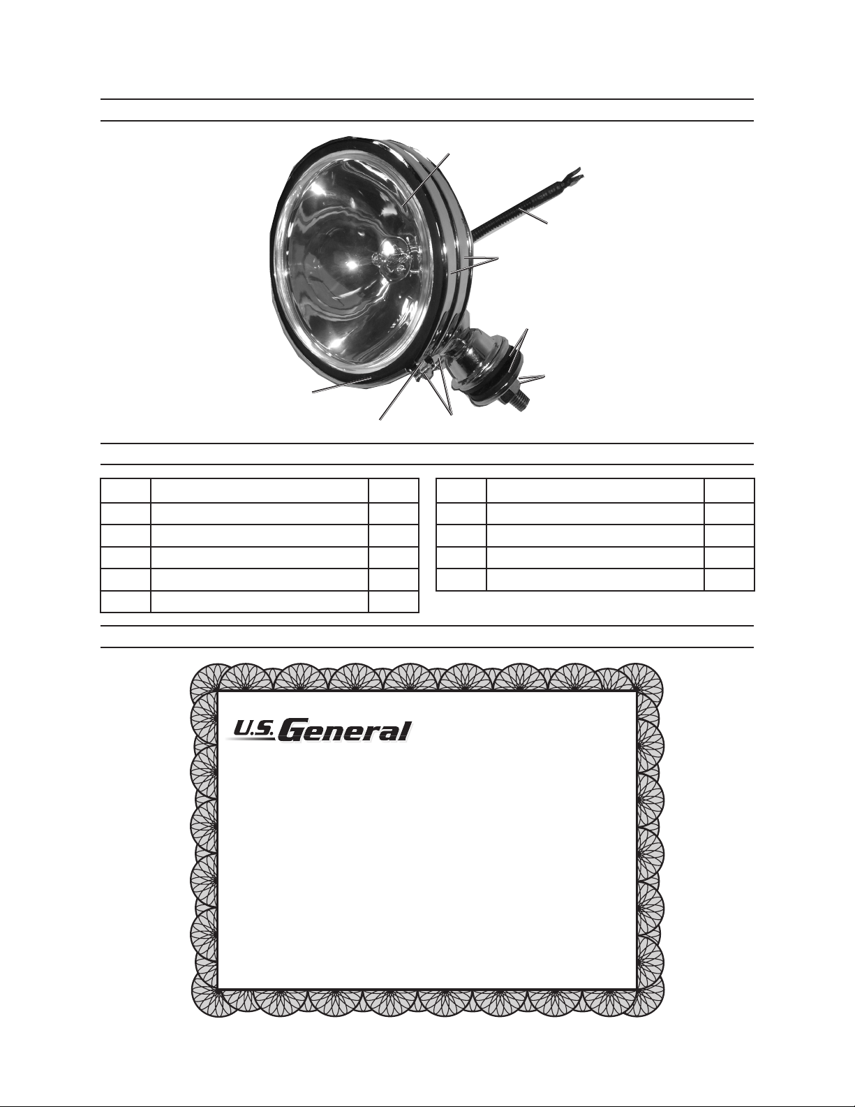
ASSEMBLY DIAGRAM
Harbor Freight Tools Co. makes every effort to assure that its products meet high quality and durability
standards, and warrants to the original purchaser that this product is free from defects in materials and
workmanship for the period of ninety days from the date of purchase. This warranty does not apply to damage
due directly or indirectly, to misuse, abuse, negligence or accidents, repairs or alterations outside our facilities,
or to lack of maintenance. We shall in no event be liable for death, injuries to persons or property, or for
incidental, contingent, special or consequential damages arising from the use of our product. Some states
do not allow the exclusion or limitation of incidental or consequential damages, so the above limitation of
exclusion may not apply to you. THIS WARRANTY IS EXPRESSLY IN LIEU OF ALL OTHER WARRANTIES,
EXPRESS OR IMPLIED, INCLUDING THE WARRANTIES OF MERCHANTABILITY AND FITNESS.
To take advantage of this warranty, the product or part must be returned to us with transportation charges
prepaid. Proof of purchase date and an explanation of the complaint must accompany the merchandise.
If our inspection verifies the defect, we will either repair or replace the product at our election or we may
elect to refund the purchase price if we cannot readily and quickly provide you with a replacement. We will
return repaired products at our expense, but if we determine there is no defect, or that the defect resulted
from causes not within the scope of our warranty, then you must bear the cost of returning the product.
This warranty gives you specific legal rights and you may also have other rights which vary from state
to state.
Limited 90 day
warranty
®
3
4
2
1
5
PARTS LIST
6
7
8
Part Description Q’ty
1 Clip 1
2 Light Assembly 1
3 Lens Assembly 1
4 Holding Rings 2
5 Holding Ring Screws 2
WARRANTY
For technical questions, please call 1-800-444-3353.
Part Description Q’ty
6 Black Ground Wire 1
7 Rubber Mounting Pads 2
8 Nut/Washer 1
9 Housing 1
Page 7SKU 95811
 Loading...