

Page 1
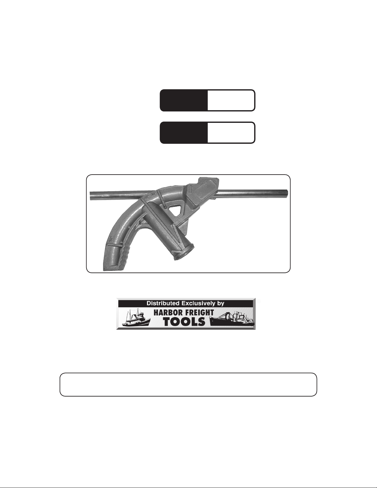
CONDUIT BENDER
Model
95805
Model
95806
®
1/2”
3/4”
ASSEMBLY AND OPERATION INSTRUCTIONS
Due to continuing improvements, actual product may differ slightly from the product described herein.
3491 Mission Oaks Blvd., Camarillo, CA 93011
Visit our website at: http://www.harborfreight.com
TO PREVENT SERIOUS INJURY, READ AND UNDERSTAND
ALL WARNINGS AND INSTRUCTIONS BEFORE USE.
Copyright© 2007 by Harbor Freight Tools®. All rights reserved. No portion of this
manual or any artwork contained herein may be reproduced in any shape or form
without the express written consent of Harbor Freight Tools.
For technical questions or replacement parts, please call 1-800-444-3353.
Page 2
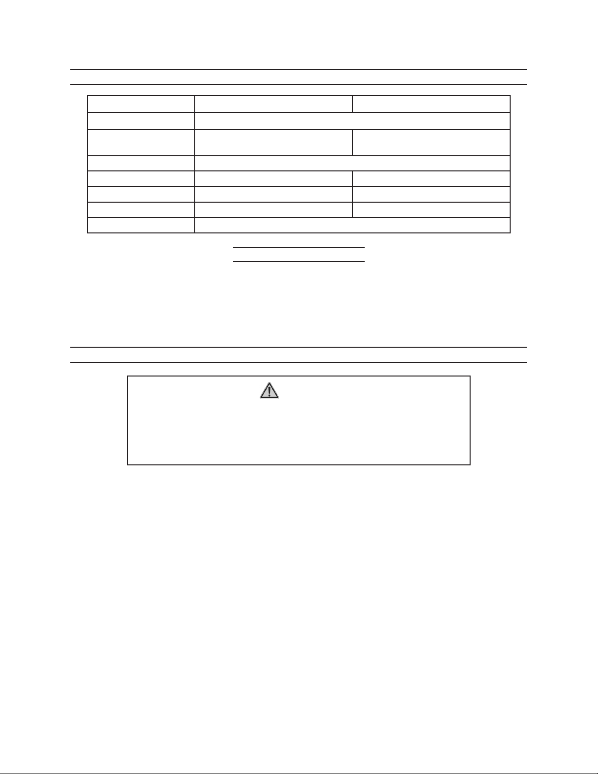
SPECIFICATIONS
Model 95805 95806
Construction Die cast aluminum
Overall Dimensions 8-1/2” L X 4-5/8” H X 1-5/8” W
Markings 30°, 45°, 90°
Handle Input 3/4” NPT 3/4” NPT
Weight 1 lb. 1.85 lb.
Conduit Capacity 1/2” 3/4”
Conduit Types EMT, RMC, or IMC
10-13/16” L X 5-1/5” H
X 1-15/16” W
SAVE THIS MANUAL
You will need this manual for the safety warnings and precautions, assembly, operating, inspection, maintenance and cleaning procedures, parts list and assembly diagram.
Keep your invoice with this manual. Write the invoice number on the inside of the front
cover. Keep this manual and invoice in a safe and dry place for future reference.
SAFETY RULES
1.
2.
3.
4.
5.
WARNING!
READ AND UNDERSTAND ALL INSTRUCTIONS
Failure to follow all instructions listed below
may result in serious injury.
SAVE THESE INSTRUCTIONS
Keep your work area clean and well lit. Cluttered benches and dark areas invite
accidents.
Stay alert. Watch what you are doing, use common sense. Do not use while
tired or under the influence of drugs, alcohol, or medication. A moment of
inattention may result in serious personal injury.
Do not overreach. Keep proper footing and balance at all times. Proper footing
and balance enables better control in unexpected situations.
Use safety equipment. Always wear eye protection. Nonskid safety shoes must
be used for appropriate conditions. Always wear ANSI-approved safety goggles
when using or performing maintenance on this tool.
Use clamps (not included) or other practical ways to secure and support the
workpiece to a stable platform. Holding the work by hand or against your body
is unstable and may lead to loss of control.
For technical questions, please call 1-800-444-3353.
Page 295805 -95806
Page 3

6.
Do not force the tool. Use the correct tool for your application. The correct
tool will do the job better and safer at the rate for which it is designed. Do not force
the tool and do not use the tool for a purpose for which it is not intended.
7.
8.
9.
10.
11.
12.
Check for any condition that may affect the tool’s operation. If damaged, have
the tool serviced before using. Many accidents are caused by poorly maintained
tools.
Make a test bend in scrap material before working on the workpiece. Make
sure you understand how and where the exact bend you want will happen.
Work on electrical conduit must meet all local, state and federal regulations.
Never attempt to bend pipe with wires or cables inside.
Be aware of both ends of conduit at all times. Be careful that the free ends of
conduit do not cause hazards to others or create a hazard to yourself, such as by
getting near electrical wiring.
WARNING! The warnings and cautions discussed in this manual cannot cover
all possible conditions and situations that may occur. It must be understood by the
operator that common sense and caution are factors which cannot be built into this
product, but must be supplied the operator.
UNPACKING
When unpacking, check to make sure that the item is intact and undamaged. If
any parts are broken, please call Harbor Freight Tools at the number shown on the cover
of this manual as soon as possible.
ASSEMBLY INSTRUCTIONS
1.
2.
This Conduit Bender comes as one piece. The only additional piece needed is a
threaded 3/4” pipe handle (between 30” and 36” long) not included.
Insert the handle into the proper end of the bender and thread in place securely.
The bender is now ready for use.
OPERATION INSTRUCTIONS
Note: Always test your desired bend on a piece of scrap material before attempting on a
workpiece. Bending properly takes a measure of experience. Techniques such as
offset bends and unbending take an exceptional degree of skill and are not covered
in this manual.
For technical questions, please call 1-800-444-3353.
Page 395805 -95806
Page 4

1.
For a 90° bend, measure the distance from the object that you start from to the point
you want the radius to end at. Subtract 5” (for 1/2” conduit bender) or 6” (for 3/4”
conduit bender) “take up” distance from this and make the Bend Mark.
2.
FIGURE 1
Measured End
3.
For 45° or 30° bend, make the Bend Mark where you want the bend to start. Prac-
tice bends can help you determine how much take up distance different bends
require.
Foot
Pedal
Line up Bend Mark
with this arrow.
Slide the Conduit Bender onto the piece of conduit you wish to bend and line up
the arrow on the Bender with the Bend mark you made in step 1 or 2, above. Ap-
ply light pressure to the handle and foot pedal and verify that the arrow still aligns
with the Bend Mark.
4.
Apply constant, simultaneous pressure to both the handle and the foot pedal to bend
the conduit. Cast into the surface on the Conduit Bender you will see three different
lines: 30°, 45°, and 90°. When the bend is complete, the line beside the desired
degree of angle will be exactly perpendicular to the piece of conduit on the floor.
Note: If simultaneous force is not applied to the handle and the foot pedal, then the conduit
may kink. Do not use a conduit that is kinked or bent too sharply.
INSPECTION, MAINTENANCE, AND CLEANING
BEFORE EACH USE, inspect the general condition of the tool.
Do not use damaged equipment. Discard tool if damaged.
Note: Replacement parts are not available for this item.
Tool service must be performed only by qualified repair personnel. Service or main-
tenance performed by unqualified personnel could result in a risk of injury.
For technical questions, please call 1-800-444-3353.
Page 495805 -95806
 Loading...