

Harbor Freight Tools 61632 Product manual
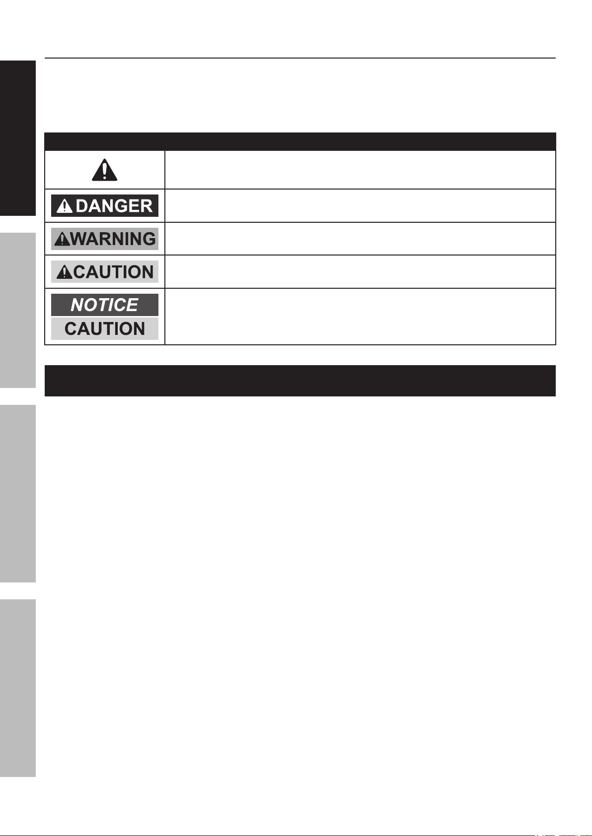
Table of Contents
SAFETY OPERATION MAINTENANCEASSEMBLY
Safety ......................................................... 2
Specifications ............................................. 3
Setup .......................................................... 3
SAFETY OPERATION MAINTENANCESETUP
Operation .................................................... 8
Maintenance ............................................... 9
Troubleshooting ......................................... 10
Parts Lists and Assembly Diagrams .......... 12
Warranty .................................................... 16
WARNING SYMBOLS AND DEFINITIONS
This is the safety alert symbol. It is used to alert you to potential
personal injury hazards. Obey all safety messages that
follow this symbol to avoid possible injury or death.
Indicates a hazardous situation which, if not avoided,
will result in death or serious injury.
Indicates a hazardous situation which, if not avoided,
could result in death or serious injury.
Indicates a hazardous situation which, if not avoided,
could result in minor or moderate injury.
Addresses practices not related to personal injury.
IMPORTANT SAFETY INFORMATION
Failure to heed these warnings may result in personal injury and/or property damage:
1. Study, understand, and follow all instructions
before operating this device.
2. Do not exceed 1500 lb. rated capacity.
3. Use only on hard, level surfaces.
4. Load saddles equally.
5. Lifting device only. Immediately after lifting,
support the vehicle with appropriate means.
6. Do not adjust safety valve.
7. Wear ANSI-approved safety goggles and
heavy-duty work gloves during use.
8. Keep clear of load while lifting and lowering.
9. Lower load slowly.
10. Do not use for aircraft purposes.
11. Lift vehicle only at manufacturerrecommended locations.
12. Inspect before every use; do not use
if parts are loose or damaged.
13. Secure load with appropriate restraint device.
14. Immediately after lifting load, ensure lift
mechanical load holding means is engaged.
15. Do not move or dolly the vehicle while on the Lift.
16. No alterations shall be made to this product.
17. Keep hands away from the Lift Arms (8, 43)
when raising or lowering the Lift.
18. Stay alert. Watch what you are doing, and use
common sense when operating a Lift. Do not use
Lift while tired or under the influence of drugs,
alcohol, or medication. A moment of inattention while
operating lifts may result in serious personal injury
19. Never allow anyone to ride Lift when it is being raised,
lowered, or while holding an ATV or motorcycle.
20. Before use, read manufacturer’s instruction
manual for the ATV or motorcycle being lifted.
21. Store idle Lift out of reach of children and
other untrained persons. Lifts are dangerous
in the hands of untrained users.
22. Lift service must be performed only by qualified repair
personnel. Service or maintenance performed by
unqualified personnel could result in a risk of injury.
23. When servicing the Lift, use only identical
replacement parts - refer to attached, productspecific parts lists and diagrams. Follow instructions
in the “Maintenance and Servicing” section of this
manual. Use of unauthorized parts or failure to follow
maintenance instructions may create a risk of injury.
24. Maintain labels and nameplates on the Lift. These
carry important information. If unreadable or missing,
contact Harbor Freight Tools for a replacement.
Page 2 For technical questions, please call 1-800-444-3353. Item 61632
25. The warnings, precautions, and instructions
discussed in this manual cannot cover all
possible conditions and situations that may occur.
The operator must understand that common sense
and caution are factors, which cannot be built into
this product, but must be supplied by the operator.
SAVE THESE INSTRUCTIONS.
Specifications
Maximum Capacity 1500 lb. (dead weight, evenly distributed)
Lift Range 4-3/4" to 16-3/8"
Dimensions 31-1/2" L x 16" W x 5-1/2" H
Setup – Before Use
Read the ENTIRE IMPORTANT SAFETY INFORMATION section at the beginning of this
manual including all text under subheadings therein before set up or use of this product.
26. The brass components of this product contain lead,
a chemical known to the State of California to cause
cancer, birth defects (or other reproductive harm).
(California Health & Safety code § 25249.5, et seq.)
SAFETYOPERATIONMAINTENANCE SETUP
SAFETYOPERATIONMAINTENANCE ASSEMBLY
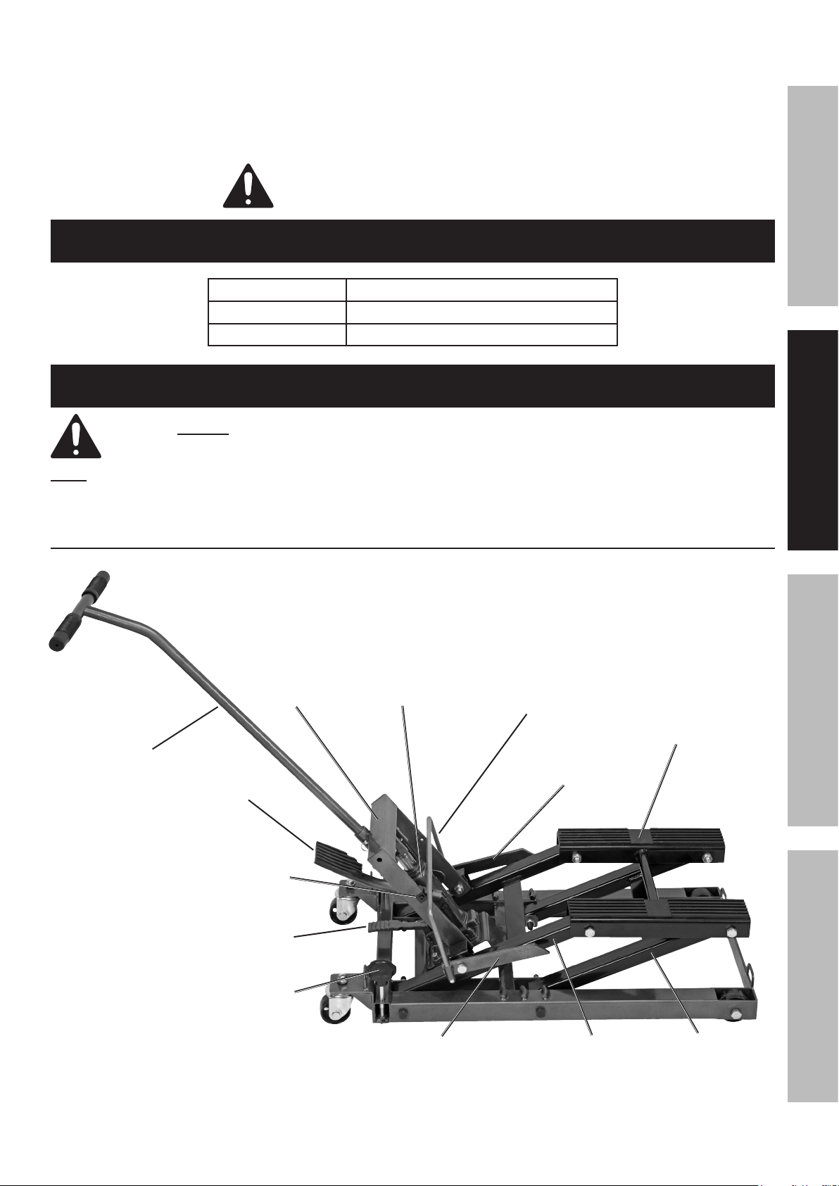
Note: For additional information regarding the parts listed in the following pages,
refer to Parts Lists and Assembly Diagrams on page 12.
Components
Stop Bar
Connecting Rod
Left Stop Bar
Handle
Foot Pedal
Stop Bar
Rod Clamp
Lifting Frame
Bottle Jack
Lift Saddle
with Rubber Pads
Release Pedal
Lock Bolt
Right Stop Bar
Figure A
Rear Lift Arm
Front Lift Arm
Page 3For technical questions, please call 1-800-444-3353.Item 61632

SAFETY OPERATION MAINTENANCEASSEMBLY
Setup – Before Use (continued)
Lift Set Up
SAFETY OPERATION MAINTENANCESETUP
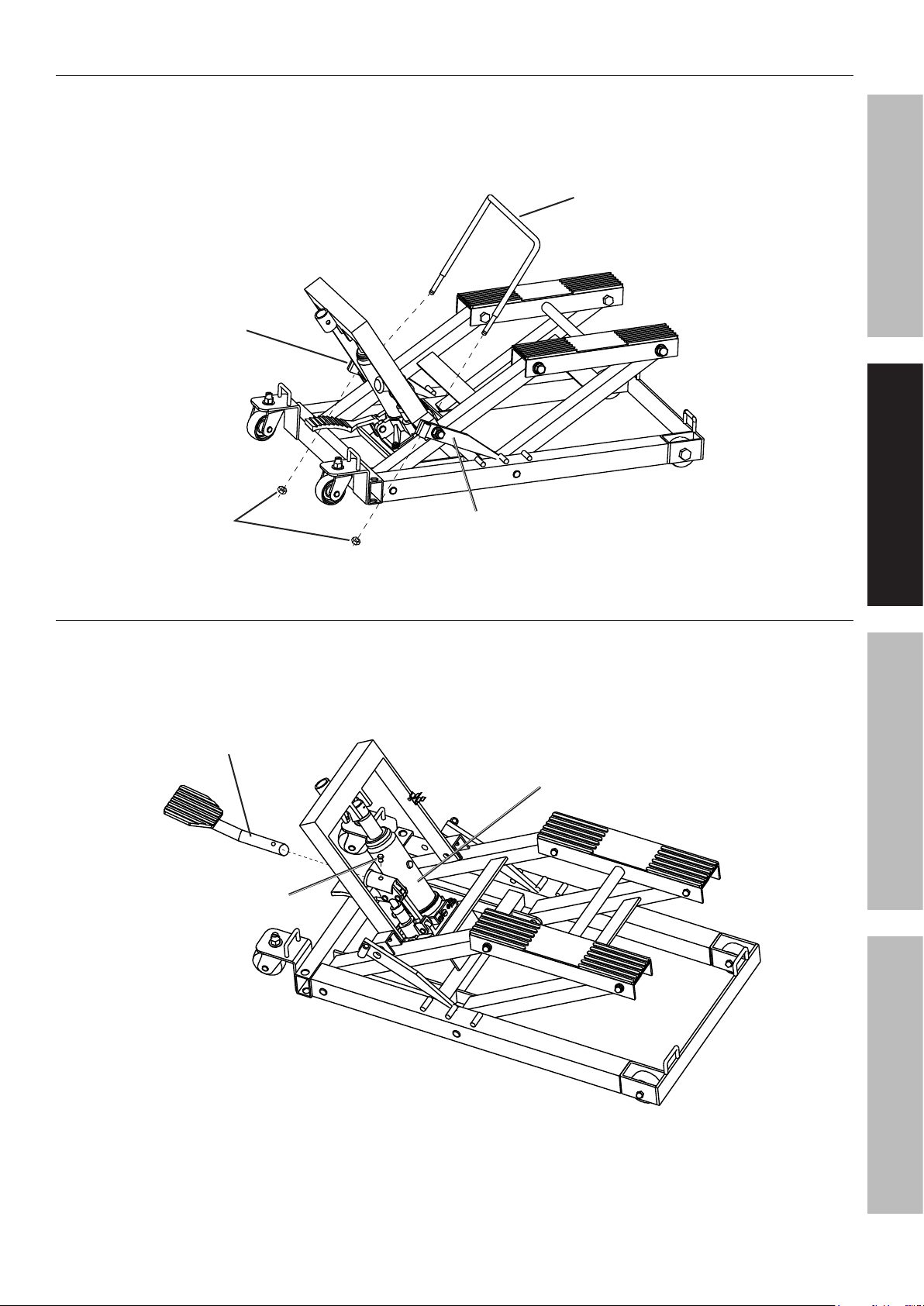
Mounting the Bottle Jack
1. Secure the Jack Assembly (30) to the Jack
Mounting Plate portion of the Bottom Base (13)
with two Bolts (23). See Figure B.
Bolt (23)
Bottle Jack (30)
Jack Mounting Plate
2. Lift the Lifting Frame (36) onto the Jack’s ram
and place the Pin (25), on the upper end of the
Jack’s arm, into the bracket on the Lifting Frame,
securing it with the Bolt (35). See Figure C.
Lifting Frame (36)
Bottom Base (13)
Figure B
Pin (25)
Bolt (35)
Bottle Jack (30)
Figure C
Page 4 For technical questions, please call 1-800-444-3353. Item 61632
Installing the Stop Bar Connecting Rod
1. Insert the two ends of the Stop Bar Connecting Rod (40)
into the sleeves on the Right and Left Stop Bars (41, 44).
2. Secure the Stop Bar Connecting Rod in place
with two Nuts (42). See Figure D.
Left Stop Bar (44)
Stop Bar Connecting Rod (40)
SAFETYOPERATIONMAINTENANCE SETUP
SAFETYOPERATIONMAINTENANCE ASSEMBLY
Nut (42)
Installing the Foot Pedal
1. Insert the Foot Pedal (27) into its
holder on the Bottle Jack (30).
2. Secure Foot Pedal in place using the Foot
Pedal Bolt (28). See Figure E.
Foot Pedal (27)
Foot Pedal Bolt (28)
Right Stop Bar (41)
Figure D
Bottle Jack (30)
Figure E
Page 5For technical questions, please call 1-800-444-3353.Item 61632
 Loading...