

Page 1
Page 2
WARNING SYMBOLS AND DEFINITIONS
This is the safety alert symbol. It is used to alert you to
potential personal injury hazards. Obey all safety messages
that follow this symbol to avoid possible injury or death.
Indicates a hazardous situation which, if not avoided,
will result in death or serious injury.
Indicates a hazardous situation which, if not avoided,
could result in death or serious injury.
Indicates a hazardous situation which, if not avoided,
could result in minor or moderate injury.
Addresses practices not related to personal injury.
IMPORTANT SAFETY INFORMATION
Read all safety warnings and instructions.
Failure to follow the warnings and instructions may result in serious injury.
Save all warnings and instructions for future reference.
The warnings and precautions discussed in this manual cannot cover all
possible conditions and situations that may occur. It must be understood
by the operator that common sense and caution are factors which cannot
be built into this product, but must be supplied by the operator.
Work area
1. Turn off the engine,
set the parking brake, and block the
tires before working on a vehicle.
2. Keep the work area clean and
well lighted. Cluttered benches
and dark areas increase the
risk of injury to persons.
Page 2 For technical questions, please call 1-888-866-5797. Items 62114
3. Keep bystanders and children away
while operating the tool. Distractions
can result in loss of control of the tool.
Page 3
Personal safety
1. Stay alert. Watch what you
are doing and use common
sense when operating the tool.
Do not use the tool while tired
or under the influence of drugs,
alcohol, or medication. A moment
of inattention while operating the tool
increases the risk of injury to persons.
Tool use and care
1. Do not force the tool. Use the correct
tool for the application. The correct
tool will do the job better and safer at
the rate for which the tool is designed.
2. Store the tool when it is idle out of
reach of children and other untrained
persons. A tool is dangerous in
the hands of untrained users.
3. Check for misalignment or binding
of moving parts, breakage of
parts, and any other condition
that affects the tool’s operation.
If damaged, have the tool serviced
before using. Many accidents are
caused by poorly maintained tools.
4. Use only accessories that are
identified by the manufacturer
for the specific tool model.
Use of an accessory not intended
for use with the specific tool model,
increases the risk of injury to persons.
2. Dress properly. Do not wear loose
clothing or jewelry. Contain long hair.
Keep hair, clothing, and gloves
away from moving parts.
Loose clothes, jewelry, or long hair
increases the risk of injury to persons as
a result of being caught in moving parts.
3. Use safety equipment.
Wear ANSI-approved safety goggles
and heavy-duty work gloves during use.
5. Avoid off-center loads. If the
Pump seems unusually hard to
operate, immediately stop. Adjust the
Ram to eliminate or diminish
an off-center load. The Ram Toe
and Plunger Toe must only be used
together to prevent an off-center load.
6. Protect the Hose. Do not drop
heavy objects on the Hose.
Avoid kinks in the Hose.
Maintain proper clearance to avoid
damage to the Hose and Couplers.
7. Inspect repair before using vehicle.
Repairs to structural or frame members
must be inspected by a qualified
technician to ensure that the
structure is still strong enough
to safely fulfill its function.
Service
1. Tool service must be performed
only by qualified repair personnel.
SAVE THESE INSTRUCTIONS.
2. When servicing a tool, use only
identical replacement parts.
Use only authorized parts.
Page 3For technical questions, please call 1-888-866-5797.Items 62114
Page 4
Specifications
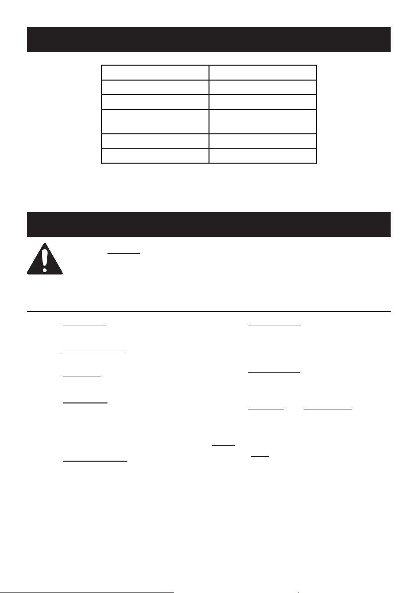
Ram Capacity 10 Tons
Ram Travel 5"
Extension Tubes
Spreader Capacity
Hose Length 5'
Setup
Read the ENTIRE IMPORTANT SAFETY INFORMATION section at the
beginning of this document including all text under subheadings therein
before set up or use of this product.
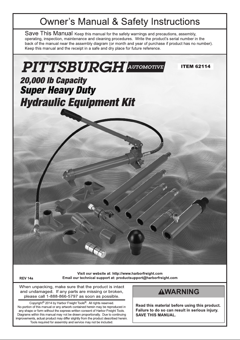
Ram Attachments
Model 62114
4-3/8", 10-3/8" (2),
14-3/8", 20-1/2"
1
⁄2 Ton
1. The Extensions connect in different
combinations to reach desired lengths.
2. The Male Connector is used to connect
the female end of the Ram to a Base.
3. The Flat Base is used on the stationary
side to spread out the force of the Ram.
4. The 90° V Base is used to offset the
force of the Ram when there is not a
straight line between the stationary
side and the damaged side, or
to spread out force on curved surfaces.
5. The Serrated Saddle is used on the
pushing end to prevent slipping.
Page 4 For technical questions, please call 1-888-866-5797. Items 62114
6. The Rubber Head is used for popping
dents out of sheet metal such as
doors or body panels and to minimize
damage to the work surface.
7. The Wedge Head is used to repair
small dents and areas located
in angles and tight spaces.
8. The Ram Toe and Plunger Toe are
used together to allow spreading in
areas that the Ram cannot fit into.
Note: The Ram Toe and Plunger
Toe must only be used together
to prevent an off-center load.
Page 5
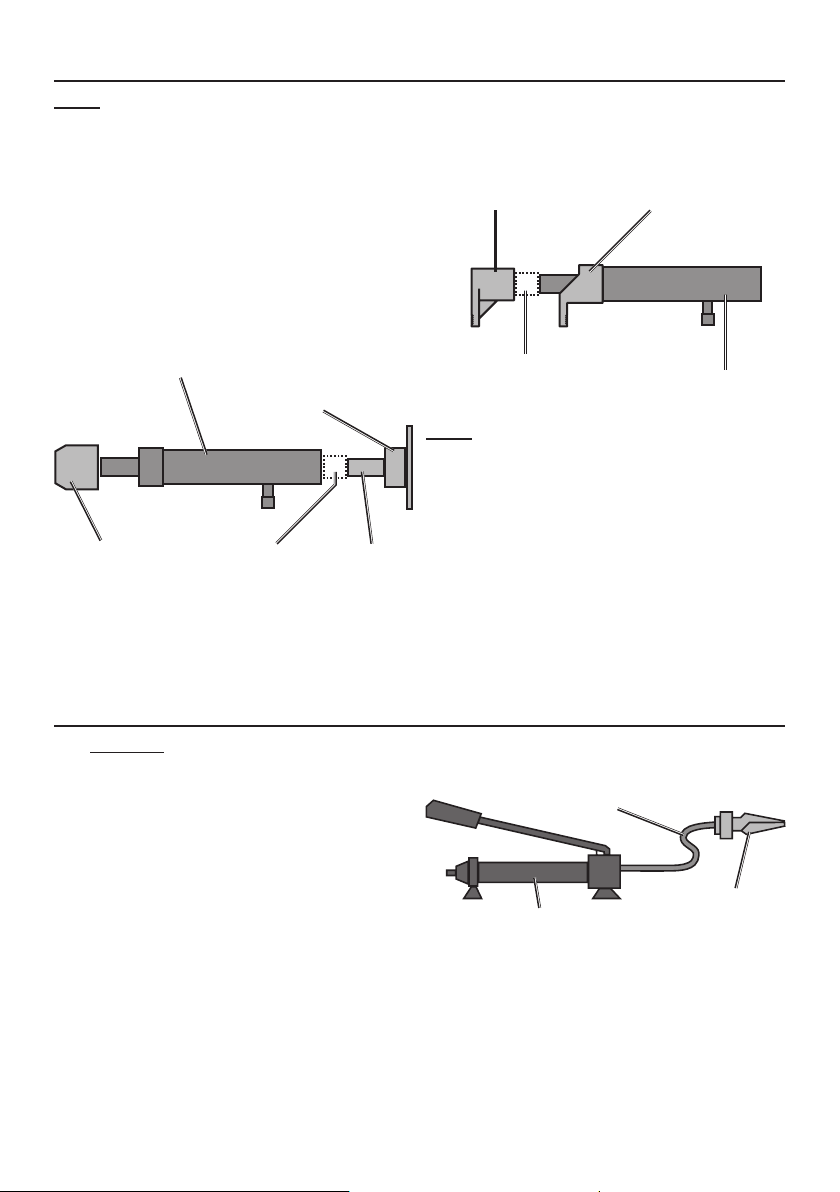
Ram Setup
Note: When positioning the Ram use a smaller attachment on the side
that is to be bent instead of the stationary side. If the stationary side is in
danger of being bent or damaged, place a block of wood or other material
behind the Flat Base to distribute pressure over a greater area.
1. Clean the end of the Hose and the
inlet on the Ram. Unscrew and
save the End Plugs located on
the end of the Hose and Ram.
2. Attach the Hose to the Ram.
3. Assemble attachments as shown below:
Plunger Toe
Ram Toe
Ram
Serrated Saddle,
Rubber Head,
or Wedge Head
90° V Base
Flat Base
(Install
Extensions
here as
needed)
or
Connector
Spreader Setup
The Spreader is used when the Ram
is too long to fit between the stationary
side and the damaged area.
1. Clean the end of the Hose and
the inlet on the Spreader.
2. Unscrew and save the
End Plugs located on the end
of the Hose and Spreader.
Male
(Install
Extensions here
as needed)
Ram
Note: If using the Ram Toe and Plunger
Toe, thread the Ram Toe onto the Ram
completely and align the Plunger Toe to it.
3. Attach the Hose to the
Spreader, as shown below:
Hose
Spreader
Pump
Page 5For technical questions, please call 1-888-866-5797.Items 62114
Page 6
Operation
Read the ENTIRE IMPORTANT SAFETY INFORMATION
section at the beginning of this manual including all text
under subheadings therein before use of this product.
1. Check the Hydraulic Fluid level, following the instructions
in the Cleaning and Maintenance section.
2. Determine which direction the frame needs to be bent.
3. Remove any obstructions that could be damaged or are in the way.
Note: When using the Pump in a vertical position,
keep the Hose end of the Pump downward.
4A. USING RAM:
a. Connect the appropriate Base to
the stationary side of the Ram,
and connect the appropriate head
to the pushing end of the Ram.
Note: When repairing larger body
panel dents such as a dented door,
fender or quarter-panel use the
Rubber Head on the pushing end.
b. If using the Ram Toe or Plunger
Toe:
Thread the Ram Toe onto the Ram
completely and align the Plunger
Toe to it. The Ram Toe and Plunger
Toe must only be used together
to prevent off-center load.
c. Position the Ram so that the Base
is resting against a frame member
opposite the damaged area. It must
also be in line with the direction in
which the damaged area needs to
be pushed. The vehicle body part
must be stronger than the area
to be bent or it may be damaged.
A block of wood or a towel may
be used to protect the body part.
d. Aim the pushing end towards the
area that needs to be repaired, and
slowly apply pressure with the Pump.
Note: To prevent damage,
do not overextend the Ram.
4B. USING SPREADER:
a. Place the Spreader so that the
hinged (pushing) arm is resting
against the part to be moved
and the stationary arm is resting
against a non-movable base.
5. Once both ends have made contact, move as far away as possible and continue to
slowly apply pressure to the damaged area until the desired bend has been made.
CAUTION! Keep hands away from contact areas and tight spaces.
The tool may slip and cause injury.
6. When the damaged area has been bent to the desired position,
slowly turn the Release Valve counterclockwise to release the
hydraulic pressure and remove the Ram or Spreader.
7. Clean all hydraulic ports and cover them with clean End Plugs.
Page 6 For technical questions, please call 1-888-866-5797. Items 62114
b. Carefully hold the Spreader in
position and apply pressure
with the Pump.
Page 7

Cleaning and Maintenance
1. Keep the surface of this tool and its
accessories free of hydraulic fluid and
grease. Use only a mild detergent and
damp cloth when cleaning. Do not use
a flammable or combustible solvent
to clean this tool or its accessories.
2. Before each use, examine the general
condition of the tool and its accessories.
Check for loose components,
misalignment, binding of moving parts,
broken parts and any other condition
that may affect its safe operation.
Do not use a damaged tool or
its damaged accessories.
3. Keep hydraulic connections clean.
Clean all hydraulic ports and replace
Dust Covers immediately after use.
4. Store the Pump with the
Release Valve open.
Filling and Bleeding Hydraulic Fluid
If the Pump operation feels spongy, or the Ram lowers while the Release Valve
is closed, there may be air in the Pump. Bleed the Pump as follows:
1. Set Pump flat on a level surface.
2. Remove the Breather Valve (P09), the
Oil Fill Screw (P07), and their seals.
3. The fluid level should be near
the bottom of the opening.
If required, add high grade
hydraulic fluid.
4. Make sure the Seal Ring is still in
place around the Fill Screw and
thread the Fill Screw into the Pump
securely. Do not use thread seal tape.
5. Firmly close the Release Valve
(P15) by turning it clockwise.
6. Press the tip of the Coupler
(P17) against a hard surface
and pump the pump handle.
7. Continue pumping, until the
hydraulic fluid coming out the end of
the Coupler tip is free of air bubbles.
8. Recheck the fluid level and
add fluid if necessary.
9. Turn the Release Valve
counterclockwise to release
the pressure in the Pump and Hose.
Changing Hydraulic Fluid
1. Change the hydraulic fluid yearly.
2. Remove the Fill Screw and tilt the
Pump to drain out the old fluid.
3. Refill the hydraulic fluid and bleed
the system several times to ensure
all air is out of the system.
Page 7For technical questions, please call 1-888-866-5797.Items 62114
Page 8
PLEASE READ THE FOLLOWING CAREFULLY
THE MANUFACTURER AND/OR DISTRIBUTOR HAS PROVIDED THE PARTS LIST AND ASSEMBLY
DIAGRAM IN THIS DOCUMENT AS A REFERENCE TOOL ONLY. NEITHER THE MANUFACTURER
OR DISTRIBUTOR MAKES ANY REPRESENTATION OR WARRANTY OF ANY KIND TO THE
BUYER THAT HE OR SHE IS QUALIFIED TO MAKE ANY REPAIRS TO THE PRODUCT, OR
THAT HE OR SHE IS QUALIFIED TO REPLACE ANY PARTS OF THE PRODUCT. IN FACT, THE
MANUFACTURER AND/OR DISTRIBUTOR EXPRESSLY STATES THAT ALL REPAIRS AND PARTS
REPLACEMENTS SHOULD BE UNDERTAKEN BY CERTIFIED AND LICENSED TECHNICIANS,
AND NOT BY THE BUYER. THE BUYER ASSUMES ALL RISK AND LIABILITY ARISING OUT OF
HIS OR HER REPAIRS TO THE ORIGINAL PRODUCT OR REPLACEMENT PARTS THERETO,
OR ARISING OUT OF HIS OR HER INSTALLATION OF REPLACEMENT PARTS THERETO.
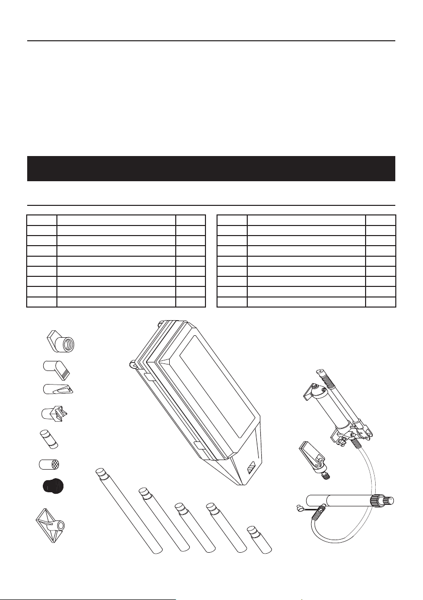
62114 Parts Lists and Diagrams
62114 Main Parts List and Assembly Diagram
Part Description Qty
01 Pump 1
02 Ram 1
03 Spreader 1
04 Storage Case 1
05a 4-3/8" Extension 1
05b 10-3/8" Extension 2
05c 14-3/8" Extension 1
05d 20-1/2" Extension 1
06 07 08 09 10
04
11 12 13
05d
05c
Part Description Qty
06 Ram Toe 1
07 Plunger Toe 1
08 Wedge Head 1
09 90º V Base 1
10 Male Connector 1
11 Serrated Saddle 1
12 Rubber Head 1
13 Flat Base 1
01
03
05b
05b
05a
02
Page 8 For technical questions, please call 1-888-866-5797. Items 62114
Page 9
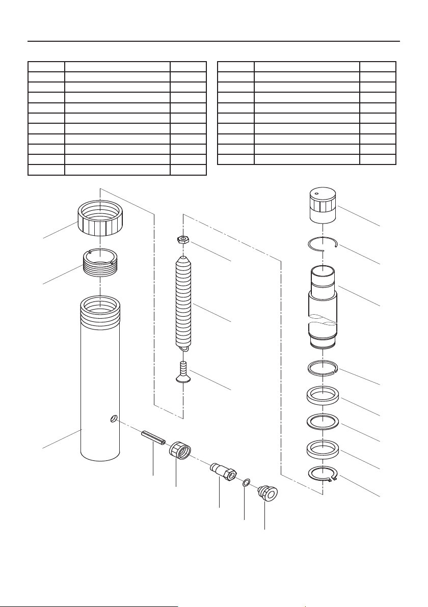
62114 Parts List and Assembly Diagram A - Ram
Part Description Qty
R01 Plastic Cap 1
R02 Circlip 1
R03 Piston 1
R04 Circlip 1
R05 Bushing 1
R06 PTFE Ring 1
R07 U-Ring 22x30x6 1
R08 Circlip Ø32 1
R09 Nut M8 1
R10 Spring 1
R12
R13
Part Description Qty
R11 Screw M8x35 1
R12 Protector Cap 1
R13 Screw 1
R14 Cylinder 1
R15 Pin Ø8x40 1
R16 Coupling Ring 1
R17 Coupling Bolt 1
R18 End Plug 1
R19 O-Ring 9.4x2.4 1
R09
R10
R01
R02
R03
R14
R15
R16
R17
R11
R04
R05
R06
R07
R08
R19
R18
Page 9For technical questions, please call 1-888-866-5797.Items 62114
Page 10
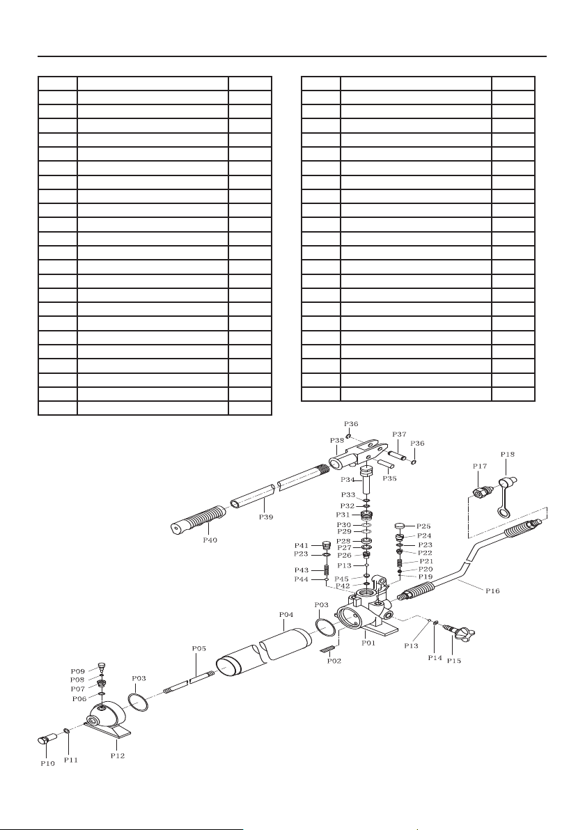
62114 Parts List and Assembly Diagram B - Pump
Part Description Qty.
P01 Base 1
P02 Oil Filter 1
P03 O-Ring 51x3.1 2
P04 Reservoir 1
P05 Screw 1
P06 Nylon Ring 1
P07 Oil Fill Screw 1
P08 Seal Ring 1
P09 Breather Valve 1
P10 Bolt 1
P11 O-Ring 9.4x2.4 1
P12 Pump Foot 1
P13 Ball Ø5.5 2
P14 O-Ring 5x3 1
P15 Release Valve 1
P16 Hose 1
P17 Coupler 1
P18 End Plug 1
P19 Ball Ø3.5 1
P20 Ball Seat 1
P21 Spring 1
P22 Screw 1
P23 O-Ring 7.8x2.2 2
Part Description Qty.
P24 Screw 1
P25 Plastic Cap 1
P26 Valve Screw Cap 1
P27 Nylon Ring 18x12.5x2 1
P28 U-Ring 12x18x6 1
P29 O-Ring 18x3.55 1
P30 Nylon Ring 24x18x1 1
P31 Cylinder 1
P32 O-Ring 11.6x2.65 1
P33 Nylon Ring 16.2x12x1.25 1
P34 Piston 1
P35 Pin 1
P36 Circlip Ø10 2
P37 Pin 1
P38 Handle Socket 1
P39 Handle 1
P40 Grip 1
P41 Screw 1
P42 Nylon Ring 1
P43 Spring 1
P44 Ball Ø8 1
P45 Ball Seat 1
Page 10 For technical questions, please call 1-888-866-5797. Items 62114
Page 11
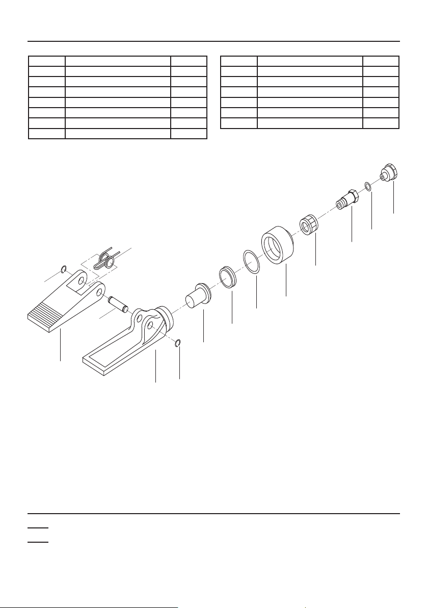
62114 Parts List and Assembly Diagram C - Spreader
Part Description Qty
S01 Pivoting Pin 1
S02 Circlip Ø12 2
S03 Pushing Arm 1
S04 Spring 1
S05 Stationary Arm 1
S06 Piston 1
S07 Cup Seal 1
S04
S02
S01
Part Description Qty
S08 O-Ring 38x3.5 1
S09 End Cap 1
S10 Coupling Ring 1
S11 Coupling Bolt 1
S12 End Plug 1
S13 O-Ring 9.4x2.4 1
S12
S13
S11
S10
S09
S08
S07
S06
S03
S02
S05
Record Product’s Serial Number Here:
Note: If product has no serial number, record month and year of purchase instead.
Note: Some parts are listed and shown for illustration purposes only,
and are not available individually as replacement parts.
Page 11For technical questions, please call 1-888-866-5797.Items 62114
Page 12

Limited 90 Day Warranty
Harbor Freight Tools Co. makes every effort to assure that its products meet high quality
and durability standards, and warrants to the original purchaser that this product is free from
defects in materials and workmanship for the period of 90 days from the date of purchase.
This warranty does not apply to damage due directly or indirectly, to misuse, abuse, negligence
or accidents, repairs or alterations outside our facilities, criminal activity, improper installation,
normal wear and tear, or to lack of maintenance. We shall in no event be liable for death,
injuries to persons or property, or for incidental, contingent, special or consequential damages
arising from the use of our product. Some states do not allow the exclusion or limitation of
incidental or consequential damages, so the above limitation of exclusion may not apply to you.
THIS WARRANTY IS EXPRESSLY IN LIEU OF ALL OTHER WARRANTIES, EXPRESS OR
IMPLIED, INCLUDING THE WARRANTIES OF MERCHANTABILITY AND FITNESS.
To take advantage of this warranty, the product or part must be returned to us with transportation
charges prepaid. Proof of purchase date and an explanation of the complaint must accompany
the merchandise. If our inspection verifies the defect, we will either repair or replace
the product at our election or we may elect to refund the purchase price if we cannot readily
and quickly provide you with a replacement. We will return repaired products at our expense,
but if we determine there is no defect, or that the defect resulted from causes not within
the scope of our warranty, then you must bear the cost of returning the product.
This warranty gives you specific legal rights and you may also
have other rights which vary from state to state.
3491 Mission Oaks Blvd. • PO Box 6009 • Camarillo, CA 93011 • 1-888-866-5797
 Loading...