

Page 1
Model
41860
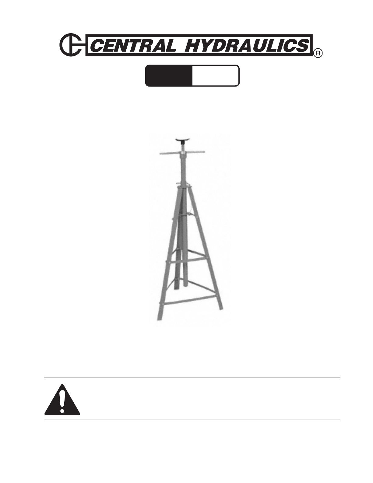
2 Ton Underhoist Safety Stand
SET UP AND OPERATING INSTRUCTIONS
Diagrams within this manual may not be drawn proportionally.
Due to continuing improvements, actual product may differ slightly from the product described herein.
Distributed exclusively by Harbor Freight Tools®.
3491 Mission Oaks Blvd., Camarillo, CA 93011
Visit our website at: http://www.harborfreight.com
Read this material before using this product.
Failure to do so can result in serious injury.
SAVE THIS MANUAL.
Copyright© 2007 by Harbor Freight Tools®. All rights reserved. No portion of this manual
or any artwork contained herein may be reproduced in any shape or form without the
express written consent of Harbor Freight Tools.
For technical questions or replacement parts, please call 1-800-444-3353.
Page 2

Assembly
Assembly of Legs (#8), Down Supports (#9), and Mid Supports (#16).
1. The top of each Leg (#8) has a closed end with a hole drilled in it. Attach a Down Support (#9) to the bottom hole on a Leg (#8) using a Bolt (#12), a Washer (#14), and a Nut
(#13). Make sure you attach to the inside of the angle iron on the Leg (#8). Do not fully
tighten yet.
2. Move up the same Leg (#8) to the middle hole and attach a Mid Support (#16) using a
Bolt (#12), a Washer (#14), and a Nut (#13).
3. Next, repeat the process adding a second Down Support (#9) and a Mid Support (#16)
to the leg you just assembled.
4. You should now have one Leg (#8) with two Down Supports (#9) and two Mid Supports
(#16). Take both remaining Legs (#8) and attach them to Down Supports (#9), and Mid
Supports (#16) on the previously assembled Leg (#8).
5. Next, put the last Down Support (#9) and Mid Support (#16) between the two remaining
Legs (#8). Tighten all of the Nuts (#13) and Bolts (#12).
6. The Upper Supports (#15) are “L” shaped with one end shorter than the other. Attach
the shorter end to the upper holes on the Legs (#8) of the tripod you just constructed
using a Bolt (#12), a Washer (#14), and a Nut (#13), for each Upper Support (#15). See
the Assembly Diagram on Page 4 to show correct position of each Upper Support (#15).
7. The Base Stand (#7) has two metal triangles welded to the top section of it, below the
Lock Pin (#11) hole. Lower the Base Stand (#7) into the tripod you just constructed,
bottom rst. The lower triangle should rest on top of the Upper Supports (#15), lining up
with the holes of both the Upper Supports (#15) and the holes on the triangle. The upper triangle should rest on top of each Leg (#8), lining up the holes in the triangles with
the holes on the end of each Leg (#8). Secure the bottom triangle to the Upper Supports (#15) using a Bolt (#12), a Washer (#14), and a Nut (#13). Repeat the process
securing the upper triangle to each Leg (#8) using a Bolt (#12), Washer (#14), and a Nut
(#13).
8. Part numbers 2,3,4,5, and 6 come pre-assembled. The Pan (#1) and the Handles (#10)
must be added to the Shaft (#6) assembly. Set the Pan (#1) on top of the Screw Rod
(#2) and attach it with a Bolt (#12). Next, screw each Handle (#10) into the threaded
holes on the Bearing (#4).
9. Take the assembled Shaft (#6) and insert it into the tube of the Base Stand (#7). Lower
it to the desired level and insert the Lock Pin (#11) to secure it at the appropriate height.
SKU 41860 Page 2
Page 3

General Usage
This Stand is used to support automobile exhaust systems and drive shafts underneath an
already hoisted vehicle. The Stand will allow hands free repair after the required part is supported.
Note!! The Two Ton High Jack Stand is 24” wide and can be used at a minimum height of
49 3/4” and a maximum height of 93 1/2”.
Safety Warnings
Use for intended purposes only.
1.
Use on at, level, hard surface capable of supporting stand and load.
2.
Inspect before use; do not use if parts loose or damaged.
3.
Do not exceed 4,000 lb. maximum weight capacity.
4.
Wear ANSI-approved safety goggles and heavy-duty work gloves during use.
5.
Read manual before set up and/or use.
6.
Make sure the hoist used to lift the car or truck is in good working order and securely
7.
locked into place after reaching desired height.
Operation
The Legs (#8) of the High Jack Stand must stand on a dry, clean, hard, level surface.
1. Turn the Handles (#10) so that the Pan (#10) retracts back into the Screw Rod (#2) as
far as it will go.
2. Position the Pan (#10) directly underneath the auto part you wish to support.
3. Remove the Lock Pin (#11) and raise the Shaft (#6) so that the Pan (#1) rests under the
selected auto part needing support. Reinsert the Lock Pin (#11).
4. Turn the Handles (#10) raising the Pan (#1) until it securely supports the auto part.
Make sure there is no wobble. If necessary tighten Handles (#10).
SKU 41860 Page 3
REV 07k
Page 4

Assembly Drawing and Parts List
No Description Qty
1 Pan 1
2 Screw Rod 1
3 Screw Nut 1
4 Bearing 1
5 Position Rod 1
6 Shaft 1
7 Base Stand 1
8 Legs 3
9 Down Support 3
10 Handle 2
11 Lock Pin 1
12 Bolt M10x20 22
13 Nut M10 21
14 Washer #10 21
15 Upper Support 3
16 Mid Support 3
Page 4SKU 41860
Page 5

LIMITED 90 DAY WARRANTY
Harbor Freight Tools Co. makes every effort to assure that its products meet high quality
and durability standards, and warrants to the original purchaser that this product is free from
defects in materials and workmanship for the period of 90 days from the date of purchase. This
warranty does not apply to damage due directly or indirectly, to misuse, abuse, negligence or
accidents, repairs or alterations outside our facilities, criminal activity, improper installation,
normal wear and tear, or to lack of maintenance. We shall in no event be liable for death, injuries to persons or property, or for incidental, contingent, special or consequential damages
arising from the use of our product. Some states do not allow the exclusion or limitation of
incidental or consequential damages, so the above limitation of exclusion may not apply to
you. THIS WARRANTY IS EXPRESSLY IN LIEU OF ALL OTHER WARRANTIES, EXPRESS
OR IMPLIED, INCLUDING THE WARRANTIES OF MERCHANTABILITY AND FITNESS.
To take advantage of this warranty, the product or part must be returned to us with
transportation charges prepaid. Proof of purchase date and an explanation of the complaint
must accompany the merchandise. If our inspection veries the defect, we will either repair or
replace the product at our election or we may elect to refund the purchase price if we cannot
readily and quickly provide you with a replacement. We will return repaired products at our
expense, but if we determine there is no defect, or that the defect resulted from causes not
within the scope of our warranty, then you must bear the cost of returning the product.
This warranty gives you specic legal rights and you may also have other rights which
vary from state to state.
3491 Mission Oaks Blvd. • PO Box 6009 • Camarillo, CA 93011 • (800) 444-3353
PLEASE READ THE FOLLOWING CAREFULLY
THE MANUFACTURER AND/OR DISTRIBUTOR HAS PROVIDED THE PARTS LIST AND
ASSEMBLY DIAGRAM IN THIS MANUAL AS A REFERENCE TOOL ONLY. NEITHER THE
MANUFACTURER OR DISTRIBUTOR MAKES ANY REPRESENTATION OR WARRANTY
OF ANY KIND TO THE BUYER THAT HE OR SHE IS QUALIFIED TO MAKE ANY REPAIRS
TO THE PRODUCT, OR THAT HE OR SHE IS QUALIFIED TO REPLACE ANY PARTS OF
THE PRODUCT. IN FACT, THE MANUFACTURER AND/OR DISTRIBUTOR EXPRESSLY
STATES THAT ALL REPAIRS AND PARTS REPLACEMENTS SHOULD BE UNDERTAKEN
BY CERTIFIED AND LICENSED TECHNICIANS, AND NOT BY THE BUYER. THE BUYER
ASSUMES ALL RISK AND LIABILITY ARISING OUT OF HIS OR HER REPAIRS TO THE
ORIGINAL PRODUCT OR REPLACEMENT PARTS THERETO, OR ARISING OUT OF HIS
OR HER INSTALLATION OF REPLACEMENT PARTS THERETO.
SKU 41860 Page 5
REV 07k
 Loading...