

Page 1

Item #41345
Self Centering Doweling Jig
Assembly and Operating Instructions
3491 Mission Oaks Blvd., Camarillo, CA 93011
Copyright 2000 by Harbor Freight T ools. All rights reserved. No portion of this manual or any artwork
contained herein may be reproduced in any shape or form without the express written consent of Harbor
Freight T ools.
For technical questions please call Harbor Fr eight Tools
at telephone number 1-800-444-3353.
Specifications:
Length: 4-3/4” Height: 2-1/2” Width: 4” Extended
Maximum Capacity: 2” Stock
Bushing Set: 2 each of 1/4”, 5/16” and 3/8”
.
Note: There are 4 holes along the top of the Jig. Only 2 of the holes accept threaded bushings. The other 2
holes accept 7/16” and 1/2” drill bits.
#41345 Page 1
REV 08/04
Page 2
Warning:
1. Read this instruction manual completely before using the Self Centering Doweling Jig.
2. Always wear ANSI approved safety goggles when working with tools and equipment. W ear a full face
shield if you are producing wood chips.
3. Keep children out of the work area. When not in use, store this product in a location that is out of reach
of children.
4. Keep work area clean. Cluttered areas invite injuries.
5. Observe work area conditions. Do not use tools in damp, wet, or poorly lit locations. Don’t expose to
rain. Keep work area well lit.
6. Do not force the tool. It will do the job better and more safely at the rate for which it was intended. Do
not use inappropriate attachments in an attempt to exceed the tool’s capacities.
7. Dress properly . Do not wear loose clothing or jewelry as they can be caught in moving parts. Non-skid
footwear is recommended. W ear restrictive hair covering to contain long hair .
8. Stay alert. Watch what you are doing. Use common sense. Do not operate any tool when you are tired.
Direction for Use:
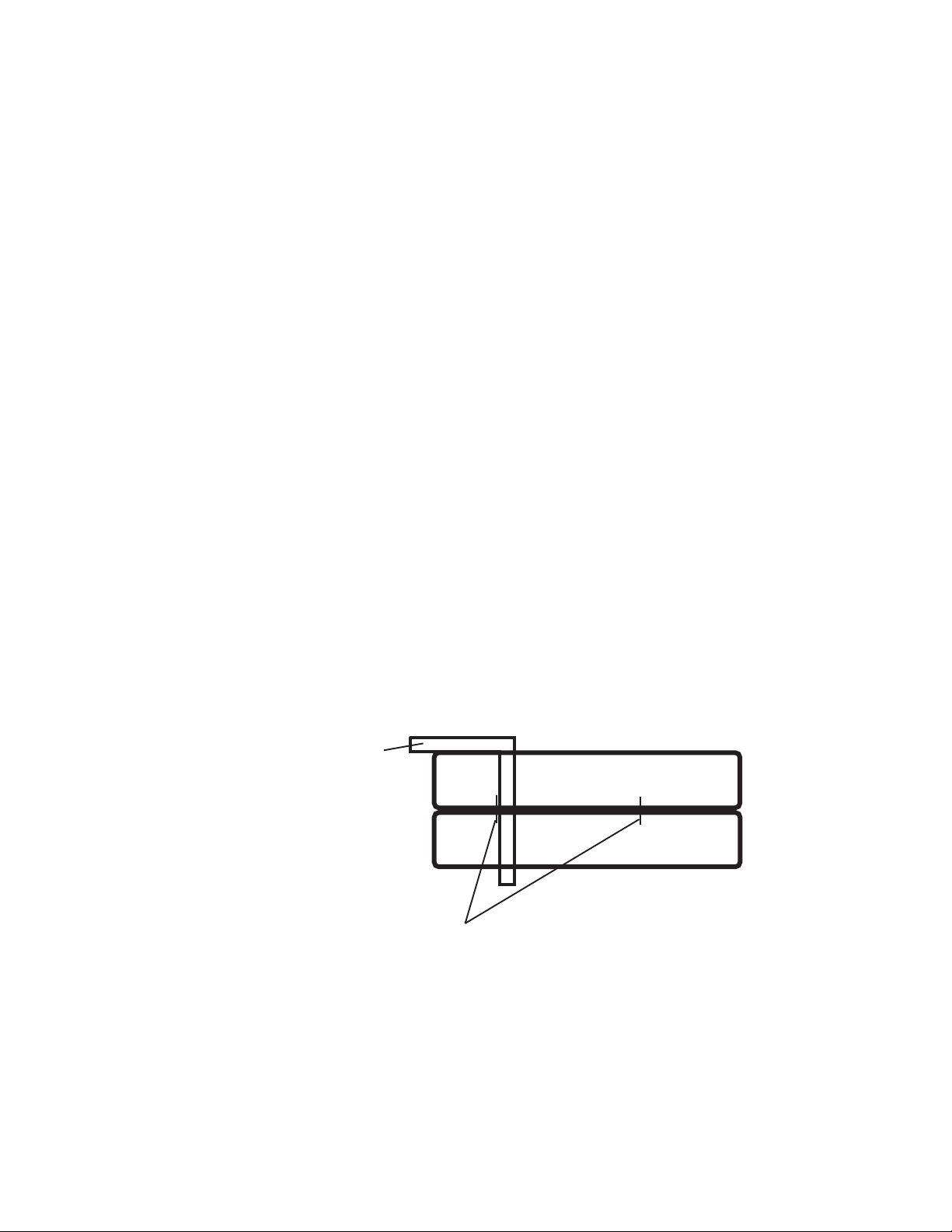
1. Line up the two boards that are to be connected by the dowels. On the side of each
board, draw a vertical mark to show where the dowels are to be located (see illustration
below).
Square Edge
2. Separate the two boards,
Top Board
and clamp the Doweling Jig
over the edge of one of the boards.
Bottom Board
Align the mark on the board
with the desired dowel diameter
(see hole sizes in Guide Block).
Insert appropriate bushings before
Vertical Marks To Show
Dowel Location
drilling the dowel hole to the depth
desired. The drilled hole will be
exactly in the center of the board edge.
#41345 Page 2
Page 3

3. W ith the dowel holes precisely drilled, it is easy to assemble the two boards together. Put glue in the
holes and on the dowels. Insert the dowels into the holes and tightly clamp the boards until glue has dried.
4. The Self Centering Doweling Jig can be used to make accurate butt joints, miter joints, and edge joints,
as well as acting as a mortising guide.
Parts Listing
Part # Description Qty Part # Description Qty
1 Screw 2
2 Adjustment Nut 1
3 Washer 2
4 Rear Pressing Block 1
5 Screw Arbor 1
6 Bushing 6
7 Spring Screw 1
Parts Diagram
8 Spring 1
9 Steel Ball 1
10 Guide Block 1
11 Leading Shaft 2
12 Front Pressing Block 1
13 Handle 1
Note: There are 4
holes along the top of
the Jig. Only 2 of the
holes accept threaded
bushings. The other 2
holes accept 7/16” and
1/2” drill bits.
PLEASE READ THE FOLLOWING CAREFULLY
THE MANUFACTURER AND/OR DISTRIBUTOR HAS PROVIDED THE PARTS DIAGRAM IN THIS MANUAL AS A
REFERENCE TOOL ONLY. NEITHER THE MANUFACTURER NOR DISTRIBUTOR MAKES ANY REPRESENTATION OR WARRANTY OF ANY KIND TO THE BUYER THAT HE OR SHE IS QUALIFIED TO MAKE ANY REPAIRS
TO THE PRODUCT OR THAT HE OR SHE IS QUALIFIED TO REPLACE ANY PARTS OF THE PRODUCT. IN
FACT, THE MANUFACTURER AND/OR DISTRIBUTOR EXPRESSLY STATES THAT ALL REPAIRS AND PARTS
REPLACEMENTS SHOULD BE UNDERTAKEN BY CERTIFIED AND LICENSED TECHNICIANS AND NOT BY
THE BUYER. THE BUYER ASSUMES ALL RISK AND LIABILITY ARISING OUT OF HIS OR HER REPAIRS TO
THE ORIGINAL PRODUCT OR REPLACEMENT PARTS THERETO, OR ARISING OUT OF HIS OR HER INSTALLATION OF REPLACEMENT PARTS THERETO.
#41345 Page 3
REV 08/04
Page 4

#41345 REV 08/04 Page 4
 Loading...