

Harbor Freight Tools 41188, 69513 Product manual

Owner’s Manual & Safety Instructions
Save This Manual Keep this manual for the safety warnings and precautions, assembly, operating,
inspection, maintenance and cleaning procedures. Write the product’s serial number in the back of the manual
near the assembly diagram (or month and year of purchase if product has no number).
Keep this manual and the receipt in a safe and dry place for future reference.
ITEMS
41188 69513
Visit our website at: http://www.harborfreight.com
REV 14l
When unpacking, make sure that the product is intact
and undamaged. If any parts are missing or broken,
please call 1-888-866-5797 as soon as possible.
Copyright© 1999 by Harbor Freight Tools®. All rights reserved.
No portion of this manual or any artwork contained herein may be reproduced in
any shape or form without the express written consent of Harbor Freight Tools.
Diagrams within this manual may not be drawn proportionally. Due to continuing
improvements, actual product may differ slightly from the product described herein.
Tools required for assembly and service may not be included.
Email our technical support at: productsupport@harborfreight.com
Read this material before using this product.
Failure to do so can result in serious injury.
SAVE THIS MANUAL.
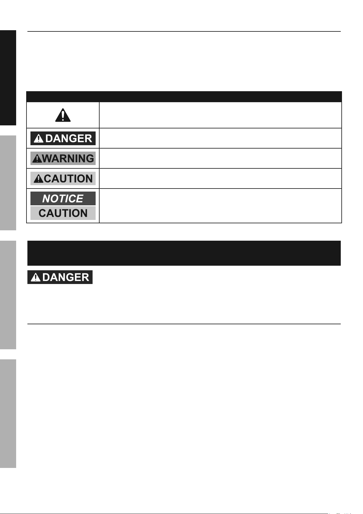
Table of Contents
Safety .................................................2
Specifications .....................................4
SAFETY OPERATION MAINTENANCEASSEMBLY
Assembly ............................................4
Operation ...........................................10
WARNING SYMBOLS AND DEFINITIONS
This is the safety alert symbol. It is used to alert you to
potential personal injury hazards. Obey all safety messages
that follow this symbol to avoid possible injury or death.
Indicates a hazardous situation which, if not avoided,
will result in death or serious injury.
Indicates a hazardous situation which, if not avoided,
could result in death or serious injury.
Indicates a hazardous situation which, if not avoided,
could result in minor or moderate injury.
Addresses practices not related to personal injury.
Maintenance ......................................14
Parts List and Assembly Diagram......18
Warranty ............................................20
IMPORTANT SAFETY INFORMATION
TO PREVENT SERIOUS INJURY AND DEATH:
Basic Safety Information
1. Do not lift more than rated load.
Be aware of dynamic loading!
Sudden load movement may briefly create
excess load causing product failure.
2. Do not operate hoist when load
is not centered under hoist.
3. Do not operate hoist with twisted,
kinked, or damaged chain or rope.
4. Do not operate a damaged or
malfunctioning gantry crane.
Inspect gantry crane carefully and
test operation before every use.
5. Do not lift people or lift loads over people.
Falling loads can injure or kill people.
6. Do not operate with other
than manual power.
7. Do not remove or cover
warning labels and/or tags.
These carry important safety information.
If unreadable or missing, contact
Harbor Freight Tools for a replacement.
8. The warnings, precautions, and instructions
discussed in this instruction manual cannot
cover all possible conditions and situations
that may occur. It must be understood by
the operator that common sense and caution
are factors which cannot be built into this
product, but must be supplied by the operator.
Page 2 For technical questions, please call 1-888-866-5797. Items 41188 69513

Assembly Specific Safety Information
1. Assemble completely according to instructions
and install Height Pins and R-pins before use.
Improper assembly can create hazards.
2. Assemble or adjust height
only with assistance.
3. Keep assembly area clean and well lit.
4. Keep bystanders out of the
area during assembly.
5. Do not assemble when tired or when under
the influence of drugs or medication.
6. Weight capacity and other product
capabilities apply to properly and
completely assembled product only.
7. Inspect the gantry crane as explained
in Frequent Inspection on page 14
after assembly but before use.
Operation Specific Safety Information
1. Use on a hard, smooth, level surface
only. The surface the gantry crane
rests on must be designed to withstand
the loads and forces imposed by the
gantry crane for the rated load.
2. Use in location that allows the operator
to move and stay clear of the load.
3. Use warning signs and barriers on the floor
beneath the gantry crane where overhead
maintenance work creates a hazard.
5. This product is not a toy. Do not allow
children to play with or near this item.
6. Use as intended only.
Do not use to handle molten material.
Do not use for aircraft purposes.
7. Use crane at lowest height
possible for the application.
8. Do not adjust height while under load.
9. Do not move loaded crane.
SAFETYOPERATIONMAINTENANCE ASSEMBLY
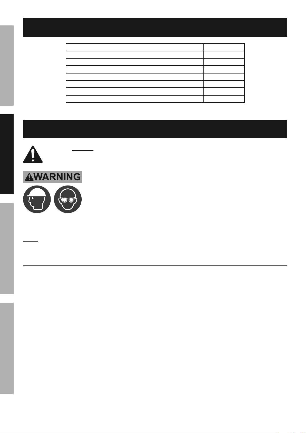
4. Wear ANSI-approved safety goggles,
ANSI-approved hard hat, and steel-toed work
boots during setup and use.
Inspection, Testing, and Maintenance
Specific Safety Information
1. Perform a “Frequent Inspection”
at least monthly, see page 14.
2. Perform a “Periodic (Thorough) Inspection”
at least yearly, see page 14.
3. More frequent inspections are needed for
gantry cranes that are used heavily.
4. Raise test loads only to the minimum
extent needed and stay well clear of
load at all times during testing.
SAVE THESE INSTRUCTIONS.
Page 3For technical questions, please call 1-888-866-5797.Items 41188 69513
Specifications
SAFETY OPERATION MAINTENANCEASSEMBLY
Load Rating 2,000 lb
Minimum Overall Height 99"
Maximum Overall Height 147-1/2"
Overall Width 128"
Minimum Vertical Clearance* (under I-Beam) 94"
Maximum Vertical Clearance* (under I-Beam) 142-1/2"
Clearance Between Posts 93-11/16"
I-Beam 3″W x 5″H
* Factor in size of beam trolley and hoist when determining required clearance.
Assembly
Read the ENTIRE IMPORTANT SAFETY INFORMATION section
at the beginning of this manual including all text under
subheadings therein before set up or use of this product.
TO PREVENT SERIOUS INJURY AND DEATH:
Wear ANSI-approved safety goggles, hard hat,
heavy-duty work gloves, and steel-toed work boots
during assembly and operation.
The correct bolts must be used during assembly. If any doubts arise regarding proper
assembly, contact Harbor Freight at the number at the bottom of this page before use.
Note: For additional information regarding the parts listed in the following pages,
refer to Parts List and Assembly Diagram on page 18.
Assembly Setup
1. More than one person will be
needed for assembly.
2. Use a large, clean and uncluttered
area for assembly.
3. Consider vertical clearance when
choosing operation area. Assemble
close to operation area.
4. Use saw horses (not included) to
support larger items such as Posts
and I-Beam during assembly.
5. The Post Insert (1) and Post Sleeve (2)
are pre-assembled.
Page 4 For technical questions, please call 1-888-866-5797. Items 41188 69513
Assembly Instructions
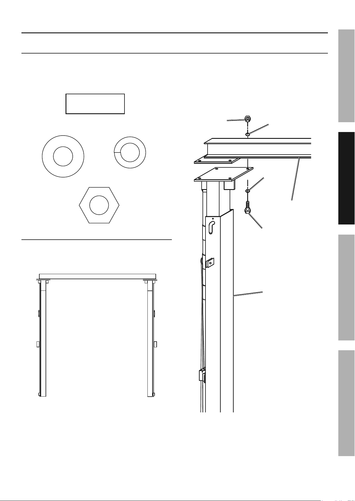
Attaching Posts to I- Beam
Hardware - 8 each:
(29) Beam
Bolt M12 x 35
Threaded
Shaft Size
(19) Washer
M12
(16) Nut
M12
(15) Spring
Washer M12
2. Attach Left Post Assembly to I-Beam
using four Beam Bolts (29), Washers (19),
Spring Washers (15), and Nuts (16).
3. Tighten connections securely.
4. Repeat for right Post Assembly.
Nut (16)
Washer
Spring
Washer (15)
(19)
I-Beam
SAFETYOPERATIONMAINTENANCE ASSEMBLY
1. Lay I-Beam (4) on the ground. Lay left
and right Post Assemblies on the ground
so Pulleys and cables are facing out.
I-Beam
(4)
Left Post
Assembly
Figure A
Right Post
Assembly
Beam
Bolt (29)
Left Post
Assembly
Figure B
Page 5For technical questions, please call 1-888-866-5797.Items 41188 69513
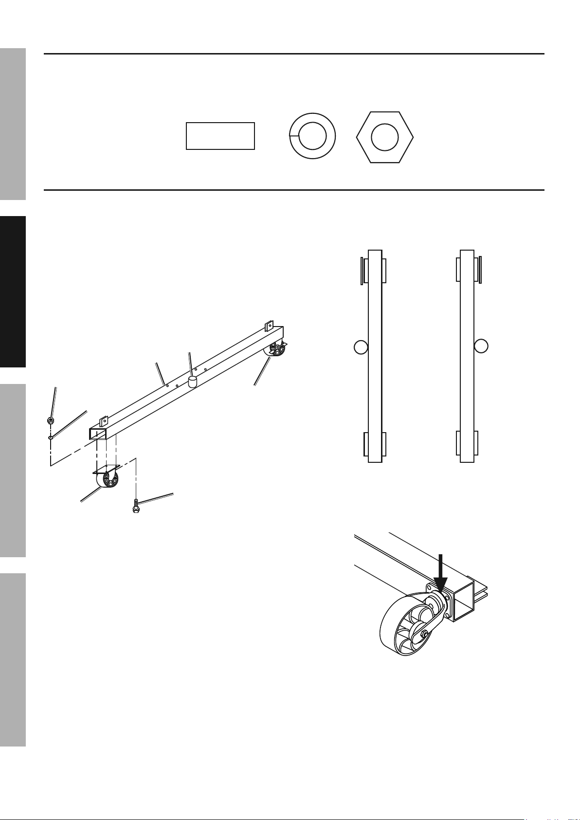
Attaching Casters to Bases
Hardware - 16 each:
(11) Caster
SAFETY OPERATION MAINTENANCEASSEMBLY
1. Attach one Swivel Caster (9a) to one end of
Base (3) using four sets of Caster Bolts (11),
Spring Washers (12) and Nuts (13).
2. Attach one Locking Swivel Caster (9b) to other
end of Base using four sets of Caster Bolts
(11), Spring Washers (12) and Nuts (13).
3. Tighten connections securely.
Base
(3)
Nut
(13)
Spring
Washer
(12)
Bolt M10 x 25
Threaded
Shaft Size
Sleeve
Locking
Swivel
Caster (9b)
(12) Washer
M10
4. Repeat for other Base, making sure
that Sleeves are to the outside and
Locking Swivel Casters are on the same end.
Sleeve
(13) Nut
M10
Locking
Swivel
Casters
Sleeve
Swivel
Caster (9a)
Caster
Figure C
Bolt
(11)
Swivel
Casters
Figure D
5. Apply grease to each Caster bearing.
Grease
here
Figure E
Page 6 For technical questions, please call 1-888-866-5797. Items 41188 69513
 Loading...