

Page 1
®
®
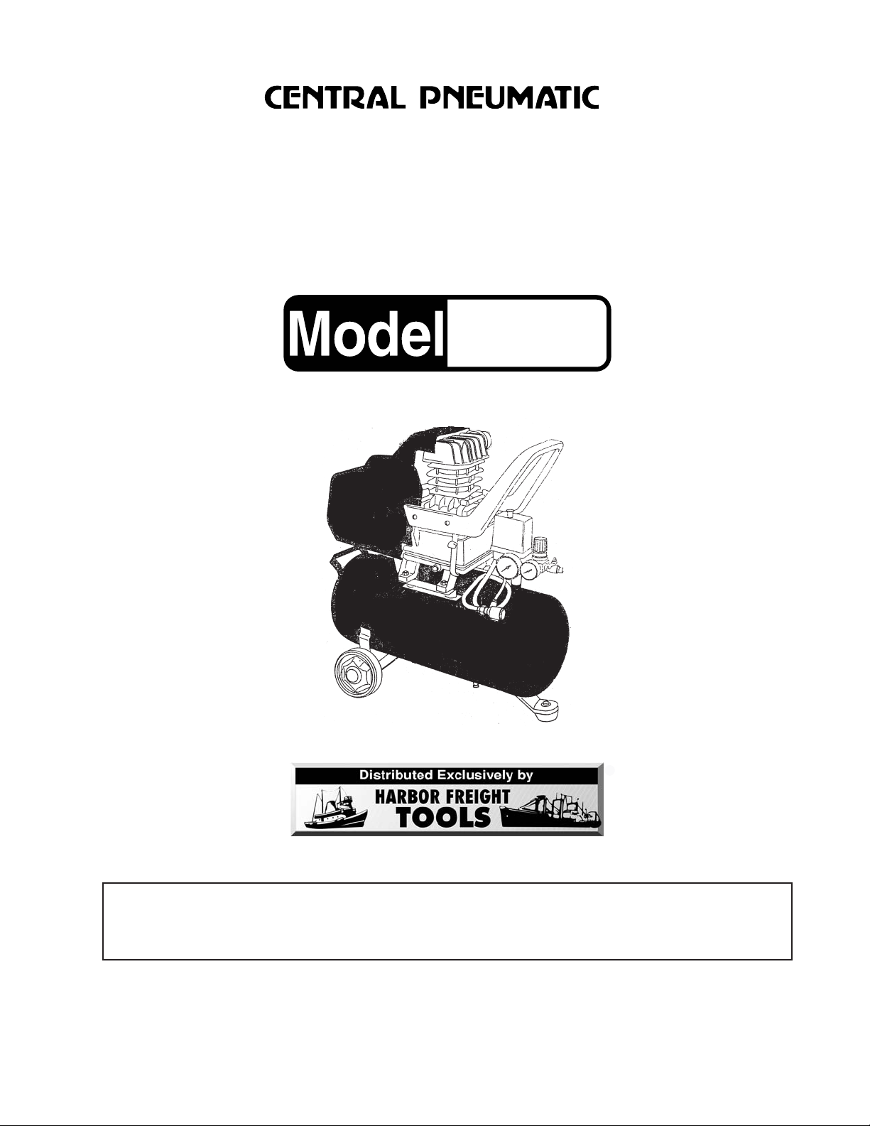
AIR COMPRESSOR
2 HP-8 GALLON
40400
ASSEMBLY & OPERATING INSTRUCTIONS
Due to continuing improvements, actual product may differ slightly from the product described herein.
3491 Mission Oaks Blvd., Camarillo, CA 93011
Visit our Web site at http://www.harborfreight.com
TO PREVENT SERIOUS INJURY,
READ AND UNDERSTAND ALL WARNINGS
AND INSTRUCTIONS BEFORE USE.
Copyright© 1999 by Harbor Freight Tools® . All rights reserved. No portion of this manual or any
artwork contained herein may be reproduced in any shape or form without the express written
consent of Harbor Freight Tools.
For technical questions and replacement parts, please call 1-800-444-3353.
REV 08/01
Page 2
THANK YOU for choosing a HARBOR FREIGHT TOOLS product. For future reference, please complete the
owner’s record below:
Model________ Serial No._____________ Purchase Date__________
SAVE THE RECEIPT, WARRANTY AND THESE INSTRUCTIONS. It is important that you read the entire
manual to become familiar with the unit BEFORE you begin assembly.
Technical Specifications
Tool Name: Air Compressor, 2HP-8 Gallon
Item Number: 40400
Motor: 2 HP
Power Source: Single Phase, 110V, 60 Hz, 3360 RPM, Single Pump
Stage, 8 Gallon
Max.Working Pressure: 115 PSI; Air Flow: 6.0 SCFM at 40 PSI, 5.0 SCFM at 90 PSI,
4.2 SCFM at 115 PSI
Press Switch: 70 PSI
Cylinder and Head: Cast Iron
Piston, Connecting
Rod, Crankcase: Cast Aluminum
Piston Diameter: 1.886"
Cylinder Honing: 45 Degree Cross Hatch
Overall Dimensions: 26" x 11-3/4" x 27"
Outlet Fittings: 1/4” x 18 NPT
Warning: The warnings, cautions and instructions discussed in this instruction manual cannot cover all possible
conditions and situations that may occur. It must be understood by the operator that COMMON SENSE AND
CAUTION ARE FACTORS WHICH CANNOT BE BUILT INTO THIS PRODUCT, BUT MUST BE SUPPLIED BY
THE OPERATOR.
Safety Warnings. Read all safety warnings before using this tool!
1. Keep work area clean. Cluttered areas invite injuries.
2. Observe work area conditions. Do not use machines or power tools in damp or wet locations. Don’t
expose to rain. Keep work area well lighted. Do not use electrically powered tools in the presence of
flammable gases or liquids.
3. Keep children away. Children must never be allowed in the work area. Do not let them handle
machines, tools, or extension cords.
4. Store idle equipment. When not in use, tools must be stored in a dry location to inhibit rust. Always
lock up tools and keep out of reach of children.
5. Do not force tool. It will do the job better and more safely at the rate for which it was intended. Do not
use inappropriate attachments in an attempt to exceed the tool capacity.
6. Use the right tool for the job. Do not attempt to force a small compressor to do the work of a larger
industrial compressor. There are certain applications for which this product was designed. Do not
modify this compressor tool and do not use this product for a purpose for which it was not intended.
REV 10/01; 08/03
SKU 40400 For technical questions, please call 1-800-444-3353. Page 2
Page 3

Safety Warnings (continued)
7. Dress properly. Do not wear loose clothing or jewelry as they can be caught in moving parts.
Protective, electrically non-conductive clothes and non-skid footwear are recommended when working.
Wear restrictive hair covering to contain long hair.
8. Use eye and ear protection. Always wear ANSI approved impact safety goggles. Wear an ANSI
approved dust mask or respirator when working around metal, wood, and chemical dusts and mists.
9. Do not overreach. Keep proper footing and balance at all times. Do not reach over or across running
machines.
10. Maintain tools with care. Keep tools sharp and clean for better and safer performance. Follow
instructions for lubricating and changing accessories. Inspect tool cords periodically and, if damaged,
have them repaired by an authorized technician. The handles must be kept clean, dry, and free from oil
and grease at all times.
11. Disconnect power. Unplug tool when not in use.
12. Remove adjusting keys and wrenches. Check that keys and adjusting wrenches are removed from
the tool or machine work surface before plugging it in.
13. Avoid unintentional starting. Be sure the switch is in the Off position when not in use and before
plugging in.
14. Stay alert. Watch what you are doing, use common sense. Do not operate any tool when you are tired.
15. Check for damaged parts. Before using any tool, any part that appears damaged should be carefully
checked to determine that it will operate properly and perform its intended function. Check for
alignment and binding of moving parts; any broken parts or mounting fixtures; and any other condition
that may affect proper operation. Any part that is damaged should be properly repaired or replaced by
a qualified technician. Do not use the tool if any switch does not turn On and Off properly.
16. Guard against electric shock. Prevent body contact with grounded surfaces such as pipes, radiators,
ranges, and refrigerator enclosures.
17. Replacement parts and accessories. When servicing, use only identical replacement parts. Use of
any other parts will void the warranty. Only use accessories intended for use with this tool. Approved
accessories are available from Harbor Freight Tools.
18. Do not operate tool if under the influence of alcohol or drugs. Read warning labels on
prescriptions to determine if your judgment or reflexes are impaired while taking drugs. If there is any
doubt, do not operate the tool.
19. Use proper size and type extension cord. If an extension cord is required, it must be of the proper
size and type to supply the correct current to the tool without heating up. Otherwise, the extension cord
could melt and catch fire, or cause electrical damage to the tool. This tool requires use of an extension
cord of 0 to 15 amps capability (up to 50 feet), with wire size rated at 16 AWG. Longer extension cords
require larger size wire. If you are using the tool outdoors, use an extension cord rated for outdoor use
(signified by “WA” on the jacket).
20. Maintenance. For your safety, service and maintenance should be performed regularly by a qualified
technician.
21. Drain compressor every day. Do not allow moisture to build up inside the compressor.
22. Make sure all equipment is rated to the appropriate capacity.
23. Avoid explosions and fire. Never place flammable objects near the compressor. Never spray water or
any flammable liquids towards the compressor.
SKU 40400 For technical questions, please call 1-800-444-3353. Page 3
Page 4

Unpacking
When unpacking, check to make sure all parts are included. Refer to the Assembly Drawing and Parts List at
the end of this manual. If any parts are missing or broken, please call Harbor Freight Tools at the number on
the cover of this manual as soon as possible.
Assembly
The Wheels need to be assembled to the Air Compressor. Insert the Axle (#54) through one of the Wheels
(#55). With these two assembled together, insert Axle (#54) through the bracket on the bottom of the Tank
Assembly (#50). Slide on Washer (#56) and the Lock Washer (#57) and tighten with the Nut (#58). Once
assembled, roll the Air Compressor to test the operation of the wheels. Periodically check to insure that
wheel and axle hardware is secure.
Operation
To assist you with operation, please refer to the Assembly Diagram and Parts List located on pages 6, 7 and 8.
Warning: Fill with compressor oil before using;
running with NO or LOW OIL voids warranty.
Checking the Oil
Make certain to add compressor oil prior to operation. The Oil Fill Plug and Oil Sight is shown on the
illustration on page 6. Only use a good quality, 30-weight, non-detergent compressor oil.
Change the oil after every 500 hours of operation.
1. By checking the level of fluid in the Oil Sight (part #20), you will be able to determine the oil level. The
oil level should be even with the dot in the center of the Oil Sight (part#20). If low, add oil until it is at
the proper level.
2. Oil is added by removing the Oil Plug (part #14) and, using a funnel to avoid spills, adding oil to the
Compressor. After Oil is added, replace the Oil Plug.
Compressor Operation
1. Plug the power cord into an electrical outlet with a grounding prong.
2. Pull up on the ON/OFF switch to turn on (see illustration on page 6). Push down on the switch to shut
the compressor off.
3. Allow the tank to fill to 80 PSI before using. With the Air Compressor on, its operation is automatic
and under the control of the internal pressure switch.
Warning: Do not remove the factory sealed Air Control Valve (see illustration on page 6); removal of
this valve voids warranty.
Hose Connections
1. Close the Air Control Valve (turn to right or left).
2. Connect the high pressure air hose to the air outlet. The outlet is 1/4” NPT. Note: For easy
connection or removal, a quick coupler (not included) should be installed on the end of the outlet.
3. Turn the Air Control Valve to the middle position to allow the air to pass.
REV 03/06
SKU 40400 For technical questions, please call 1-800-444-3353. Page 4
Page 5

Compressor Operation (continued)
NOTE: IF THE COMPRESSOR SUDDENLY SHUTS OFF, check and reset the unit’s
Overload Protection (59). To reduce the chance of this occurring, eliminate the
use of an extension cord.
Caution: The pressure switch is adjustable but changes to the pressure levels are not recommended;
any change to the automatic On/Off pressure levels will cause additional stress on the motor which
may result in shortened motor life.
Using the Safety Valve
The Safety Valve (see illustration on page 6 for location) is used when decompression is needed quickly and
efficiently.
1. Press the ON/OFF switch down.
2. Pull on the Safety Valve ring to release pressure.
Empty Air and Condensation
The Petcock (#53) release valve is located underneath the Tank Assembly (#50). It must be used daily to
release all trapped air and moisture through this valve. It will also get rid of any condensation that may cause
tank corrosion.
Warning: Do not open the Petcock (#53) so that more than four threads are showing.
1. Push down on the ON/OFF switch to turn the compressor off.
2. Unscrew the Petcock (#53) two to three turns.
3. When all pressure is released, close the Petcock (#53) again.
Warning: To reduce the risk of fire or explosion, never spray flammable liquids in a
confined area. Always operate the compressor in a well ventilated area. Do not smoke
while spraying. Do not spray where sparks or flames are present. Keep compressor as
far from spray area as possible.
Never directly inhale the compressed air produced by a compressor. It is not
suitable for breathing purposes.
Never weld on the air tank of this Compressor. Welding of the tank could affect
tank strength and result in an extremely hazardous condition.
To avoid the potential for electric shock, never use this Compressor outdoors
when it is raining, and never use the Compressor on a wet surface.
Never point any nozzle or sprayer toward a person or animal.
SKU 40400 For technical questions, please call 1-800-444-3353. Page 5
REV 01/06
Page 6

Air Compressor Diagram
PLEASE READ THE FOLLOWING CAREFULLY
THE MANUFACTURER AND/OR DISTRIBUTOR HAS PROVIDED THE PARTS DIAGRAM IN THIS
MANUAL AS A REFERENCE TOOL ONLY. NEITHER THE MANUFACTURER NOR DISTRIBUTOR MAKES
ANY REPRESENTATION OR WARRANTY OF ANY KIND TO THE BUYER THAT HE OR SHE IS QUALIFIED
TO MAKE ANY REPAIRS TO THE PRODUCT OR THAT HE OR SHE IS QUALIFIED TO REPLACE ANY
PARTS OF THE PRODUCT. IN FACT, THE MANUFACTURER AND/OR DISTRIBUTOR EXPRESSLY STATES
THAT ALL REPAIRS AND PARTS REPLACEMENTS SHOULD BE UNDERTAKEN BY CERTIFIED AND
LICENSED TECHNICIANS AND NOT BY THE BUYER. THE BUYER ASSUMES ALL RISK AND LIABILITY
ARISING OUT OF HIS OR HER REPAIRS TO THE ORIGINAL PRODUCT OR REPLACEMENT PARTS
THERETO, OR ARISING OUT OF HIS OR HER INSTALLATION OF REPLACEMENT PARTS THERETO.
SAFETY VALVE
SHROUD
CYLINDER HEAD
FILTER SCREW
HANDLE
AIR PRESSURE SWITCH
REGULATED VALVE
DRAIN VALVE
CONTROL VALVE
AIR PRESSURE METER
AIR PRESSURE METER
TANK ASSEMBLY
Hex Head Bolt
part # 11
To drain the oil
remove this bolt.
REV 03/06
SKU 40400 For technical questions, please call 1-800-444-3353. Page 6
Page 7

Parts List
traPnoitpircseDytQtraPnoitpircseDytQ
1wercStekcoS403roticapaC1
2daeHrednilyC113revoCkcaB1
3teksaGdaeHrednilyC123naFriAdecro
4evlaV133gniRmetS1
5teksaGrednilyC143duorhS1
6rednilyC153gniRmetS2
7teksaG163niP2
1-8,8gniRnoisserpmoC273evlaVpirtS1
2-8notsiP183wercS
9notsiPniPtsirW193eerged09woblE1
01notsiP104ebuTniarD1
11tuNdaeHxeH114evlaVkcehC1
21wercSdessorC424ebuT1
31eldnaH13
41reniateRliO144evlaVdetalugeR1
51doRgnitcennoC154teltuO1
61esacknarCteksaG164hctiwSerusserPriA1
71tloBdaeHxeH67
81ylbmessArevoCdnE184reteMerusserPriA1
91rehsaW194evlaVytefaS1
02thgiSliO105yssAknaT1
12gniRmetS115wercS1
22re
32yssAenoCtfahsknarC135kcocteP1
42tloBdaeHxeHrennI145elxA2
52esaCknarC155leehW2
62wercSgnippaTfleSdessor
72evirDrotoM175rehsaWkcoL2
82tuN185tuN2
92rehsaW195noitcetorPdaolrevO1
hsaW125rehsaWrebbuR1
C165rehsaW2
F1
retliF/retliF1
4evlaVniarD1
4reteMerusserPriA1
Note: Some parts listed and shown on this page are for illustration purposed only and are not
available individually as replacement parts.
REV 01/06
SKU 40400 For technical questions, please call 1-800-444-3353. Page 7
Page 8

Assembly Diagram
REV 01/06
SKU 40400 For technical questions, please call 1-800-444-3353. Page 8
 Loading...