

Page 1
AIR FILAIR FIL
®
AIR FIL
AIR FILAIR FIL
TER, REGULATER, REGULA
TER, REGULA
TER, REGULATER, REGULA
TOR ANDTOR AND
TOR AND
TOR ANDTOR AND
LUBRICALUBRICA
LUBRICA
LUBRICALUBRICA
TORTOR
TOR
TORTOR
40312
ASSEMBLY AND OPERATING INSTRUCTIONS
3491 Mission Oaks Blvd., Camarillo, CA 93011
Visit our Web site at http://www.harborfreight.com
Copyright © 2000 by Harbor Freight Tools. All rights reserved. No portion of this
manual or any artwork contained herein may be reproduced in any shape or form
without the express written consent of Harbor Freight Tools.
For technical questions and replacement parts, please call 1-800-444-3353
Page 2

Specifications
erusserPmumixaMISP051
eziStelnIriAhcni8/3
snoisnemiDtnuoMselohdetagnole,retnecotretnec,sehcni2/1-2
eguaGhtiwerusserPelbatsujdA
serutaeF
thgieW.bl5.4
noitacirbuLelbatsujdA
srevoclwoblateM
Save This Manual
You will need the manual for the safety warnings and precautions , assembly
instructions, oper ating and maintenance procedures, parts list and diagram. Keep
your invoice with this manual. Write the invoice number on the inside of the front
cover. Keep the manual and in voice in a safe and dry place for future reference.
Safety Warnings and Precautions
WARNING: When using tool, basic safety precautions should always be followed to reduce the risk of personal injury and damage to equipment.
Read all instructions before using this tool!
1. Keep work area c lean. Cluttered areas invite injuries.
2. Observe work area conditions. Do not use machines or pow er tools in
damp or wet locations. Don’t expose to rain. Keep w ork area well lighted.
Do not use electrically powered tools in the presence of flammable gases or
liquids.
3. Keep c hildren away. Children must never be allowed in the work area. Do
not let them handle machines, tools, or extension cords.
4. Store idle equipment. When not in use, tools must be stored in a dry
location to inhibit rust. Always lock up tools and keep out of reach of children.
5. Do not force tool. It will do the job better and more safely at the rate for
which it was intended. Do not use inappropriate attachments in an attempt to
exceed the tool capacity.
6. Do not overreach. Keep proper footing and balance at all times. Do not
reach over or across running machines.
7. Use the right tool for the job. Do not attempt to force a small tool or
attachment to do the work of a larger industrial tool. There are certain
SKU 40312 Page 2
Page 3

applications for which this tool was designed. Do not modify this tool and do
not use this tool for a purpose for which it was not intended.
8. Use eye and ear protection. Always wear ANSI approved impact safety
goggles. W ear a full face shield if y ou are producing metal filings or wood
chips. W ear an ANSI approved dust mask or respirator when w orking around
metal, wood, and chemical dusts and mists.
9. Maintain tools with care. Keep tools sharp and clean f or better and saf er
performance. Follow instructions for lubricating and changing accessories.
Inspect tool cords periodically and, if damaged, have them repaired by an
authorized technician.
10. Stay alert. Watch what y ou are doing, use common sense. Do not operate
any tool when you are tired.
11. Check f or damaged parts. Before using any tool, any part that appears
damaged should be carefully checked to determine that it will operate properly
and perform its intended function. Check for alignment and binding of moving
parts; any broken parts or mounting fixtures; and any other condition that may
affect proper operation. An y part that is damaged should be properly repaired
or replaced by a qualified technician.
12. Replacement parts and accessories. When servicing, use only identical
replacement parts. Use of any other parts will void the warranty. Only use
accessories intended for use with this tool.
13. Do not operate tool if under the influence of alcohol or drugs. Read
warning labels on prescriptions to determine if your judgment or reflexes are
impaired while taking drugs. If there is any doubt, do not operate the tool.
14. Maintenance. For your safety, service and maintenance should be performed
regularly by a qualified technician.
15. WARNING! The brass components of this product contain lead, a chemical
known to the State of California to cause birth defects (or other reproductive
harm). (California Health & Safety code § 25249.5,
et seq.
)
Caution: Do not remove P art #A1 Visi-Dome from the lubricator.
Attempting to do so may damage the seal and thread.
Warning: The warnings, cautions, and instructions discussed in this instruction
manual cannot cover all possible conditions and situations that may occur. It
must be understood by the operator that common sense and caution are factors which cannot be built into this product, but must be supplied by the operator.
REV 02e, 07f
SKU 40312 Page 3
Page 4

Unpacking
When unpacking, check to make sure the follo wing parts are included.
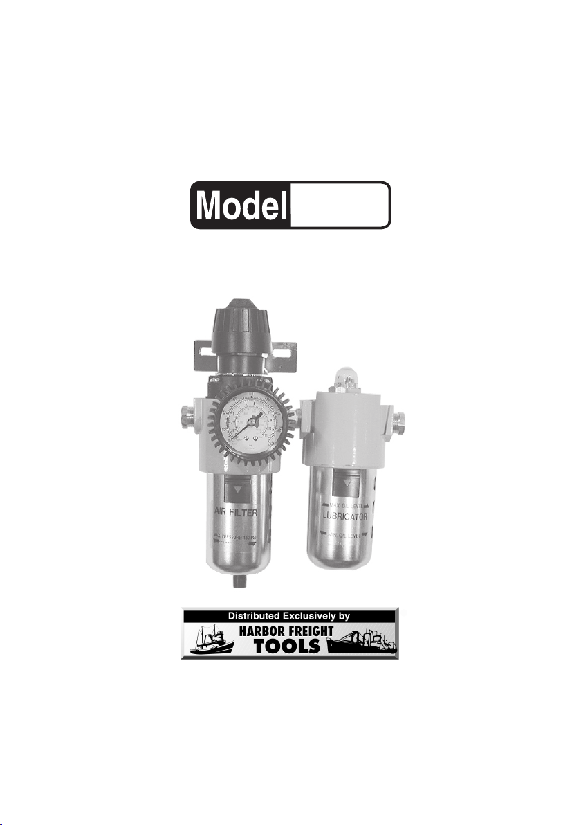
1) Air Filter / Regulator 2) Lubricator 3) Double-sided Fitting
If any parts are missing or broken, please call Harbor Freight Tools at the number
on the cover of this manual.
Installation
The diagram below sho ws the general connections for the Air Filter-Regulator and
Lubricator.
1. Find the 1/4 inch, double-sided Fitting (27) and apply brass fitting compound
to both sides.
2. Hand screw the Fitting into the Air Filter Body (12), right input side.
3. T ake the Lubricator Body (A7) and align its output connection to the Fitting
and hand screw the Fitting a few turns into the Lubricator Body.
Screw (1)
Pressure Adjusting
Knob (3)
Holder (6)
Air Flow (from
Compressor)
Air Filter Body (12)
Quick Release Button
Metal Bowl Guard (26)
Regulator Spring (14) button
Fitting (27)
To Air Tool
Lubricator Body (A7)
Quick Release Button
Metal Bowl Guard (A15)
SKU 40312 Page 4
Page 5

4. T urn the Lubricator Body cloc kwise, tightening the Fitting to the Air Filter Body
(12) and the Lubricator Body (A7).
Note that the arrows imprinted on top of each body should be pointing all in
the same direction.
5. Align both bodies so that their bowls are facing down.
6. Attach the mounting support Holder (6) to the Air Filter if the assembly is to
be mounted to a flat surface (Refer to the Assembly Drawings at the end of
this manual).
- Remove Screw (1) and pull up and remove the Adjusting Knob (3).
- Remove the Panel Mount Nut (4) by turning it counterclockwise.
- Insert the Holder (6) and replace the Panel Mount Nut, the Adjusting Knob,
and finally, the screw .
7. Secure the whole assembly by the Holder to a flat surf ace using the
appropriate hardware (not supplied).
8. Connect the compressor air output hose or pipe to the air inlet connector on
the Lubricator Body .
9. Connect the air output hose or pipe to the Air Filter output connector.
10. Press on the Lubricator Quick Release Button and pull off the Metal Bowl
Guard (A15).
11. Twist off the Plastic Bowl (A14) and add air lubricator oil to the maximum
level.
12. Press up on the Plastic Bowl to replace it.
13. Snap in the Metal Bowl Guard.
Operation
1. T urn on the Compressor and chec k for air leaks .
If any are found, turn the Compressor off and fix the leak.
2. With the Compressor ON, turn the Pressure Adjusting Knob (3) to adjust the
air pressure as read on the Gauge (13).
3. Adjust the oil flow by viewing the Visi-dome (1A) and adjusting the Oil Feed
Adjustment Screw (A3).
4. Press on the Regulator Spring (14) button to expel any accumulated moisture
from the Plastic Bowl (23). Do this daily.
SKU 40312 Page 5
Page 6

Maintenance
#metInoitpircseD
41gnirpSrotalugeR
51ylbmessAevlaV
61gnir-O
71redloH
81elffaBreripS
91tnemelEretliF
02elffaBallerbmU
12doRwercS
22gnir-O
32lwoBcitsalP
42evlaVniarDxelF
52eveelSniarDxelF
62drauGlwoBlateM
72dedis-elbuoD,"4/1,gnittiF
1. Check oil lev el in Lubricator Plastic Bowl daily. Refill if below minimum level .
2. Press on the Regulator Spring (14) button to expel any accumulated moisture
in the Plastic Bowl (23).
Air Filter Parts List
#metInoitpircseD
1wercS
2bonKkcoL
3bonKgnitsujdA
4tuNtnuoMlenaP
5wercS
6redloH
7tennoB
8yssAwercSgnitsujdA
9gnirpSrotalu
01marhpaiD
11gulP
21ydoB
31eguaG
geR
THE MANUFACTURER AND/OR DISTRIBUTOR HAS PROVIDED THE PARTS DIAGRAM
IN THIS MANUAL AS A REFERENCE TOOL ONLY. NEITHER THE MANUFACTURER
NOR DISTRIBUTOR MAKES ANY REPRESENTATION OR WARRANTY OF ANY KIND TO
THE BUYER THAT HE OR SHE IS QUALIFIED TO MAKE ANY REPAIRS TO THE
PRODUCT OR THAT HE OR SHE IS QUALIFIED TO REPLACE ANY PARTS OF THE
PRODUCT. IN FA CT, THE MANUFACTURER AND/OR DISTRIBUTOR EXPRESSLY
STATES THat ALL REPAIRS AND PARTS REPLACEMENTS SHOULD BE UNDERTAKEN
BY CERTIFIED AND LICENSED TECHNICIANS AND NOT BY THE BUYER. THE BUYER
ASSUMES ALL RISK AND LIABILITY ARISING OUT OF HIS OR HER REPAIRS TO THE
ORIGINAL PRODUCT OR REPLACEMENT PARTS THERETO, OR ARISING OUT OF HIS
OR HER INSTALLATION OF REPLACEMENT PARTS THERETO.
PLEASE READ THE FOLLOWING CAREFULLY
SKU 40312 Page 6
Page 7

Air Filter Assembly Drawing
NOTE: Some parts are listed and shown for
illustration purposes only and are not available
individually as replacement parts.
SKU 40312 Page 7
Page 8

Lubricator Parts List Lubricator Assembly Drawing
#metInoitpircseD
1Aemod-isiV
2Agnir-O
3AwercStnemtsujdAdeeFliO
4Agnir-O
5AtuNpaC
6Agnir-O
7AydoBrotacirbuL
8Agnir-O
9Are
01A)etag(evlaVediuG
11AdoRwercS
21AesoH
31Agnir-O
41AlwoBcitsalP
51AdrauGlwoBlateM
NOTE: Some parts are listed and shown
for illustration purposes only and are not
available individually as replacement
parts.
When ordering parts from this list, add an
“A” prefix to the part number illustrated in
the Assembly Drawing.
tpadA
Caution: Do not remove Part #A1 Visi-Dome from the lubricator.
Attempting to do so may damage the seal and thread.
SKU 40312 Page 8
REV 05/02
 Loading...