

Page 1

COMPRESSED AIR
DRYER
Model 40211
ASSEMBLY and OPERATING
INSTRUCTIONS
3491 Mission Oaks Blvd., Camarillo, CA 93011
Visit our Web site at http://www.harborfreight.com
Copyright© 2002 by Harbor Freight Tools®. All rights reserved. No portion of
this manual or any artwork contained herein may be reproduced in any shape or
form without the express written consent of Harbor Freight Tools.
For technical questions and replacement parts, please call 1-800-444-3353
Page 2

Specifications
Power Source 110/120 Volts, 60 Hz
Horsepower 1/4 HP
Max. Operating Pressure 140 PSI
Recommended Operating Pressure 100 PSI
Air Inlet / Outlet 1/2” Steel Pipe -14 NPT
Flow Capacity 21.6 C.F.M.
Pressure/Temperative Range 32 - 39 PSI (2-80C)
For R-134A Refrigerant
Note: This Compressed Air Dryer uses R-134A Refrigerant.
Note: Not for medical use. Do not use for hyperbaric chambers.
Save This Manual
You will need the manual for the safety warnings and precautions, assembly instructions,
operating and maintenance procedures, parts list and diagram. Keep your invoice with this
manual. Write the invoice number on the inside of the front cover. Keep the manual and
invoice in a safe and dry place for future reference.
Safety Warnings and Precautions
WARNING: When using tool, basic safety precautions should always be followed to reduce the risk of personal injury and damage to equipment.
Read all instructions before using this tool!
1. Keep work area clean. Cluttered areas invite injuries.
2. Observe work area conditions. Do not use machines or power tools in damp or wet
locations. Don’t expose to rain. Keep work area well lighted. Do not use electrically
powered tools in the presence of flammable gases or liquids.
3. Keep children away. Children must never be allowed in the work area. Do not let
them handle machines, tools, extension cords, or air hoses.
4. Store idle equipment. When not in use, tools must be stored in a dry location to
inhibit rust. Always lock up tools and keep out of reach of children.
5. Use the right tool for the job. Do not attempt to force a small tool or attachment to
do the work of a larger industrial tool. There are certain applications for which this tool
was designed. It will do the job better and more safely at the rate for which it was
intended. Do not modify this tool and do not use this tool for a purpose for which it
was not intended .
6. Dress properly. Do not wear loose clothing or jewelry as they can be caught in
moving parts. Protective, electrically non-conductive clothes and non-skid footwear
are recommended when working. Wear restrictive hair covering to contain long hair.
7. Use eye and ear protection. Always wear ANSI approved impact safety goggles.
Wear a full face shield if you are producing metal filings or wood chips. Wear an ANSI
approved dust mask or respirator when working around metal, wood, and chemical
dusts and mists.
REV 07/03; 08/03; 01/05; REV 11/05; REV 09/06
For technical questions, please call 1-800-444-3353. Page 2SKU 40211
Page 3

8. Do not overreach. Keep proper footing and balance at all times. Do not reach over or
across running machines or air hoses.
9. Maintain tools with care. Keep tools clean for better and safer performance. Follow
instructions for lubricating and changing accessories. Inspect tool cords and air hoses
periodically and, if damaged, have them repaired by an authorized technician. The
handles must be kept clean, dry, and free from oil and grease at all times.
10. Remove adjusting keys and wrenches. Check that keys and adjusting wrenches
are removed from the tool or machine work surface before plugging it in.
11. Avoid unintentional starting. Be sure the switch is in the Off position when not in
use and before plugging in.
12. Stay alert. Watch what you are doing, use common sense. Do not operate any tool
when you are tired.
13. Check for damaged parts. Before using any tool, any part that appears damaged
should be carefully checked to determine that it will operate properly and perform its
intended function. Check for alignment and binding of moving parts; any broken parts
or mounting fixtures; and any other condition that may affect proper operation. Any
part that is damaged should be properly repaired or replaced by a qualified technician.
Do not use the tool if any switch does not turn On and Off properly.
14. Guard against electric shock. Prevent body contact with grounded surfaces such as
pipes, radiators, ranges, and refrigerator enclosures.
15. Replacement parts and accessories. When servicing, use only identical
replacement parts. Use of any other parts will void the warranty. Only use accessories
intended for use with this tool. Approved accessories are available from Harbor Freight
Tools.
16. Do not operate tool if under the influence of alcohol or drugs. Read warning
labels on prescriptions to determine if your judgment or reflexes are impaired while
taking drugs. If there is any doubt, do not operate the tool.
17. Use proper size and type extension cord. If an extension cord is required, it must be
of the proper size and type to supply the correct current to the tool without heating up.
Otherwise, the extension cord could melt and catch fire, or cause electrical damage to
the tool. Check your compressor’s manual for the appropriate size cord.
18. Maintenance. For your safety, maintenance should be performed regularly by a
qualified technician.
19. Compressed air only. Never use combustible gases as a power source.
Note: Performance of the compressor (if powered by line voltage) may vary depending
on variations in local line voltage. Extension cord usage may also affect tool performance.
For technical questions, please call 1-800-444-3353. Page 3SKU 40211
Page 4
Warning: The warnings, cautions, and instructions discussed in this instruction manual
cannot cover all possible conditions and situations that may occur. It must be understood by the operator that common sense and caution are factors which cannot be
built into this product, but must be supplied by the operator.
Unpacking
When unpacking, check to make sure the parts listed on page 9 are included. If any parts
are missing or broken, please call Harbor Freight Tools at the number on the cover of this
manual as soon as possible.
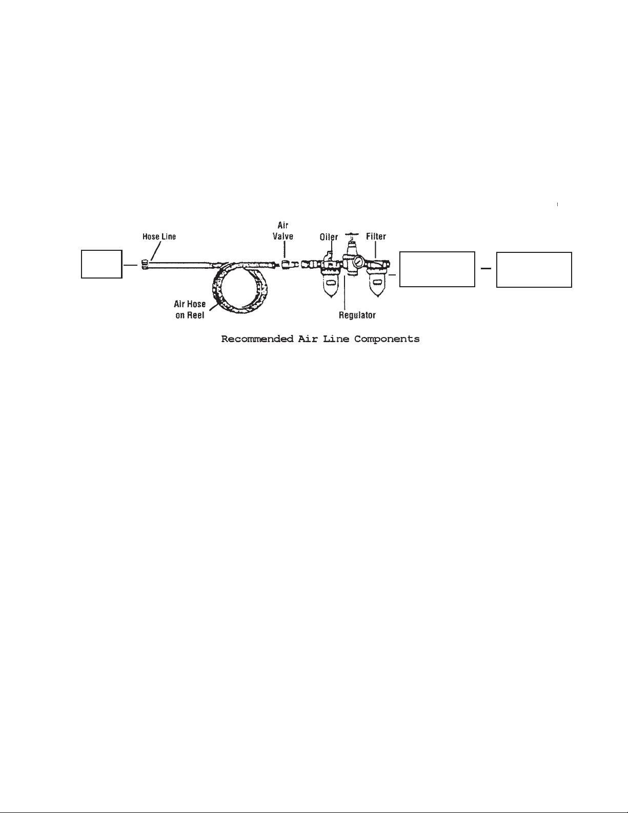
Tool
Air
Dryer
Compressor
For best service you should incorporate an oiler, regulator, and inline filter, as shown in the
diagram above. Hoses, couplers, oilers, regulators, and filters are all available at Harbor
Freight Tools.
Note: You will need to prepare valves and couplers (not included) from the compressor to the
Air Dryer (1/2” Steel Pipe-14 NPT) and from the Air Dryer (1/2” Steel Pipe-14 NPT) to the tool.
Use pipe thread seal tape or pipe dope in all of the connections. If you are not using an
automatic oiler system, before operation, add a few drops of Pneumatic Tool Oil to the airline
connection. Add a few drops more after each hour of continual use. Check the air connection
for leaks before use.
Installation
1. Install the Air Dryer at least 2 feet from the wall on all four sides. This will give the unit
proper ventilation and allow space for maintenance and repair.
2. Make sure the floor is level.
3. Do not expose the unit to rain or any moisture.
4. Install the unit out of direct sunlight and away from any heat sources. Otherwise, the
cooling function of the unit will continually run, eventually overheating the Air Dryer.
5. Position a small bucket to capture foul water from the drain hose at the bottom of the
unit. Condensation water can be piped to a floor drain, if available; be sure to follow
local plumbing codes.
Note: Electrical installation and installation of a recommended bypass valve (not included)
are covered on page 5.
For technical questions, please call 1-800-444-3353. Page 4SKU 40211
Page 5

Installation (continued)
Note: We recommend that a bypass valve (not included) be added between the
Air Inlet (#6) and the Air Outlet (#7) for applications when the Air Dryer is not needed.
The bypass valve must be installed by a plumber or an authorized service technician.
See FIGURE 1.
Bypass Valve
FIGURE 1
Air Inlet (#6)
Air Outlet (#7)
Shut-off
Compressor
Shut-off
Air Dryer
Note to professional installer: The shut-offs (not included) for both the air inlet and air
outlet, must be plumbed below the horizontal piping containing the bypass valve. See FIG-
URE 1.
Using the bypass valve (not using the Air Dryer).
If you do not wish to use the Air Dryer with a certain application follow these steps:
1. Turn off and unplug the compressor and the Air Dryer.
2. Engage the shut-off valves, closing both of the air inlets.
3. Open the bypass valve.
4. Plug in and turn on your compressor and you’re ready to work without the Air Dryer.
Using the Air Dryer without the bypass valve.
1. Before plugging in the compressor or the Air Dryer, open both of the shut-off valves.
2. Close the bypass valve.
3. Plug in and turn on the Compressor and Air Dryer.
Electrical Installation
Instructions for the following wiring diagram are on page 6.
Pre-wired at the factory
FIGURE 2
Green (Hot)
Black (Hot)
Black (Neutral)
White
Green/ White (Ground)
Green (Ground)
Electrical Cord
For technical questions, please call 1-800-444-3353. Page 5SKU 40211
REV 01/03
Page 6

Electrical Installation (continued)
Refer to FIGURE 2 on page 5.
Note: Wiring must be done by a professionally certified electrician.
1. Remove the side panel.
2. The top three wires of the electrical box are pre-wired at the factory.
3. The wires from the electrical cord (not included) must be rated for a minimum of 10-1/2
load rated amps, and the plug on the electrical cord must be three pronged
(recommended 12 gauge, 3 conductor electrical cord). Wire the bottom three wires as
indicated in the wiring diagram in FIGURE 2 on page 5.
Note: Make sure you run the wires through the hole in the rear panel using a UL approved
cable clamp (not provided), so that you can close the unit when you are finished wiring.
See FIGURE 3.
FIGURE 3
Remove this Side Panel to
expose the electrical box
Rear Panel
Run electrical cord
through opening in
rear panel.
FIGURE 4
Note: The gauge should
always be in a range
between 32 - 39 PSI
(2-80C).
If not, turn off Air Dryer
and let the unit cool.
Try it again after it cools.
If the light is still lit, take
the unit to an authorized
service technician.
For technical questions, please call 1-800-444-3353. Page 6SKU 40211
Operation
Note: If problem light is on, turn off Air Dryer and let the unit cool.
Try it again after it cools. If the light is still lit, take the unit to an
authorized service technician.
Problem
Power
Light
Light
On/Off Switch
Temperature
Gauge
REV 01/03; 08/03; 01/05; REV 11/05
Model
Air Inlet
Capacity
Voltage
Air Inlet Temp
Horse Power
40211
1/2” Stl.Pipe-14 NPT
21.6 CFM
110V
175 F
1/4 HP
Page 7

Operation (continued)
Note: The Air Dryer works using “Refrigerant 134A”. The refrigerant system does not need to
be serviced unless the unit begins to leak. If the unit leaks refrigerant, take it to an
authorized service technician.
Note: Decide whether you want to use the Air Dryer or bypass the unit. Follow the instruc-
tions for using or not using the bypass valve on page 5. If you set the valves for “Using
the Air Dryer”, follow the instructions below.
1. Turn on the unit with the Switch on the control panel. See FIGURE 4 on page 6.
2. If, after the unit has warmed up, you don’t hear the fan running, there is likely not
enough pressure to turn on the pressure switch. Turn off the unit and the compressor.
Close the Air Inlet (#6). Then, turn the Air Dryer back on and it will build up pressure
in a few minutes. Open the Air Inlet (#6). Turn on your compressor and let air in slowly
at first. During operation, dry air will pass through the unit to the tool or application.
3. When you are finished, stop the air compressor first. Continue to run the Air Dryer until
all of the compressed air runs through the system.
4. Turn off the Air Dryer.
Note: If the Air Dryer stops and the Problem Light (See FIGURE 4 on page 6) goes on, the
unit is running at too high of a temperature or pressure. Let the unit cool. Unplug the
Air Dryer. Open the side panel (See FIGURE 3 on page 6) and push the reset button
on the Pressure Switch (#14). See the Assembly drawing on page 10. Plug in the unit
and restart. If the Problem Light stays on, or comes on continually, take the unit to an
authorized service technician.
Troubleshooting
Warning!! Repairing this unit (other than trying to reset the Pressure Switch (#14), as men-
tioned above) should only be performed by an authorized service technician.
Problem 1: Unit shuts off by itself.
Reason: Temperature or pressure is too high or fan is overheated. Or, the Condenser (#11) is dirty.
Solution: Reset pressure switch as described in the note above, or clean the Condenser (#11) as
described in Maintenance on page 8.
Problem 2: No power light when the unit is on.
Reason: Loose connections at wiring panel.
Solution: Check the connections and tighten.
Problem 3: Unit won’t cool/dry air.
Reason: Water in the refrigeration unit because of: Auto drain blocked, bad valve, bad connection to
capacitor, bad capacitor, bad fan unit, low air pressure.
Solution: Clean auto drain and tube, replace valve, check capacitor connection, replace capacitor,
replace fan unit, turn up air pressure on compressor.
Problem 4: Unit buzzes and won’t operate.
Reason: Bad capacitor.
Solution: Replace capacitor.
Only done by a qualified electrician or service technician.
Problem 5: Fan isn’t working at the correct temperature and pressure.
Reason: Bad fan bearing, bad fan capacitor, or bad temperature switch.
Solution: Replace fan bearing, fan capacitor, or temperature switch.
Only done by a qualified electrician or service technician.
Problem 6: Pressure on the inlet or outlet valves increase for no reason.
Reason: Bad internal pressure valve.
Solution: Replace internal pressure valve.
REV 02/05
For technical questions, please call 1-800-444-3353. Page 7SKU 40211
Page 8

Troubleshooting Continued
Problem 7: Ice accumulating in the dryer, and/or a pressure loss through the unit.
Reason: This may be caused by the formation of ice inside.
Solution: The Hot Gas Bypass Valve (not shown in the Parts List or Assembly Diagram) needs to be
adjusted. This adjustment should only be done after consultation with our technical support
service at: 1-800-444-3353.
Maintenance
Note: Maintenance must be performed by an authorized service technician.
Never attempt to adjust the temperature; this
adjustment should only be done by an authorized service technician.
1. See FIGURE 5. Periodically clean the
Condenser (#11). Use a dust collector and
an air gun to clean dirt and debris. Be careful
not to get too close to the unit with high
pressure as you will damage the unit. If
grease or oil are built up and won’t blow off,
wash it off with a mild detergent.
FIGURE 5
Note: The internal parts illustrated for step 2 below
are a guide for the authorized service
technician. They cannot be ordered
separately. Only the parts on the parts list
on page 9 can be ordered.
2. See FIGURE 6. Washing the auto drain. To
wash the auto drain, close the 1/2 ball Filter
Valve on top of the drain. Pull the manual
drain shaft handle to empty the water. Take
apart the drain and the fixed screw. Clean
the strainer from inside to out. Take apart
the manual drain shaft and the seal end cap.
Take off the float ball and valve seat. Clean
each component and reassemble.
FIGURE 6
Strainer
Seal
Screw
Seal
Float Ball
Valve
Seal
Spring
Seal End Cap
Manual Drain
Shaft
REV 07/03; 02/05; 01/07
For technical questions, please call 1-800-444-3353. Page 8SKU 40211
Page 9

Parts List
Part No. Description
1 U-Housing
2 Left Plate
3 Right Plate
4 Base Plate
5 Connect Pipe
6 Air Inlet
7 Air Outlet
8 Evaporator
9 Filter Valve
10 Drain
11 Condenser
12 Compressor
13 Fan Control
Pressure Switch
14 Pressure Switch
15 Fan Motor
16 Fan Bracket
17 Fan
PLEASE READ THE FOLLOWING CAREFULLY
THE MANUFACTURER AND/OR DISTRIBUTOR HAS PROVIDED THE PARTS DIAGRAM IN THIS
MANUAL AS A REFERENCE TOOL ONLY. NEITHER THE MANUFACTURER NOR DISTRIBUTOR MAKES ANY REPRESENTATION OR WARRANTY OF ANY KIND TO THE BUYER THAT
HE OR SHE IS QUALIFIED TO MAKE ANY REPAIRS TO THE PRODUCT OR THAT HE OR SHE
IS QUALIFIED TO REPLACE ANY PARTS OF THE PRODUCT. IN FACT, THE MANUFACTURER
AND/OR DISTRIBUTOR EXPRESSLY STATES THAT ALL REPAIRS AND PARTS REPLACEMENTS SHOULD BE UNDERTAKEN BY CERTIFIED AND LICENSED TECHNICIANS AND NOT
BY THE BUYER. THE BUYER ASSUMES ALL RISK AND LIABILITY ARISING OUT OF HIS OR
HER REPAIRS TO THE ORIGINAL PRODUCT OR REPLACEMENT PARTS THERETO, OR ARISING OUT OF HIS OR HER INSTALLATION OF REPLACEMENT PARTS THERETO.
NOTE: Some parts are listed and shown for illustration purposes only and are not available
individually as replacement parts.
For technical questions, please call 1-800-444-3353. Page 9SKU 40211
Page 10

Assembly Drawing
13
For technical questions, please call 1-800-444-3353. Page 10SKU 40211
Page 11

SCHEMATIC DIAGRAM
REV 12/04
For technical questions, please call 1-800-444-3353. Page 11SKU 40211
 Loading...