

Page 1
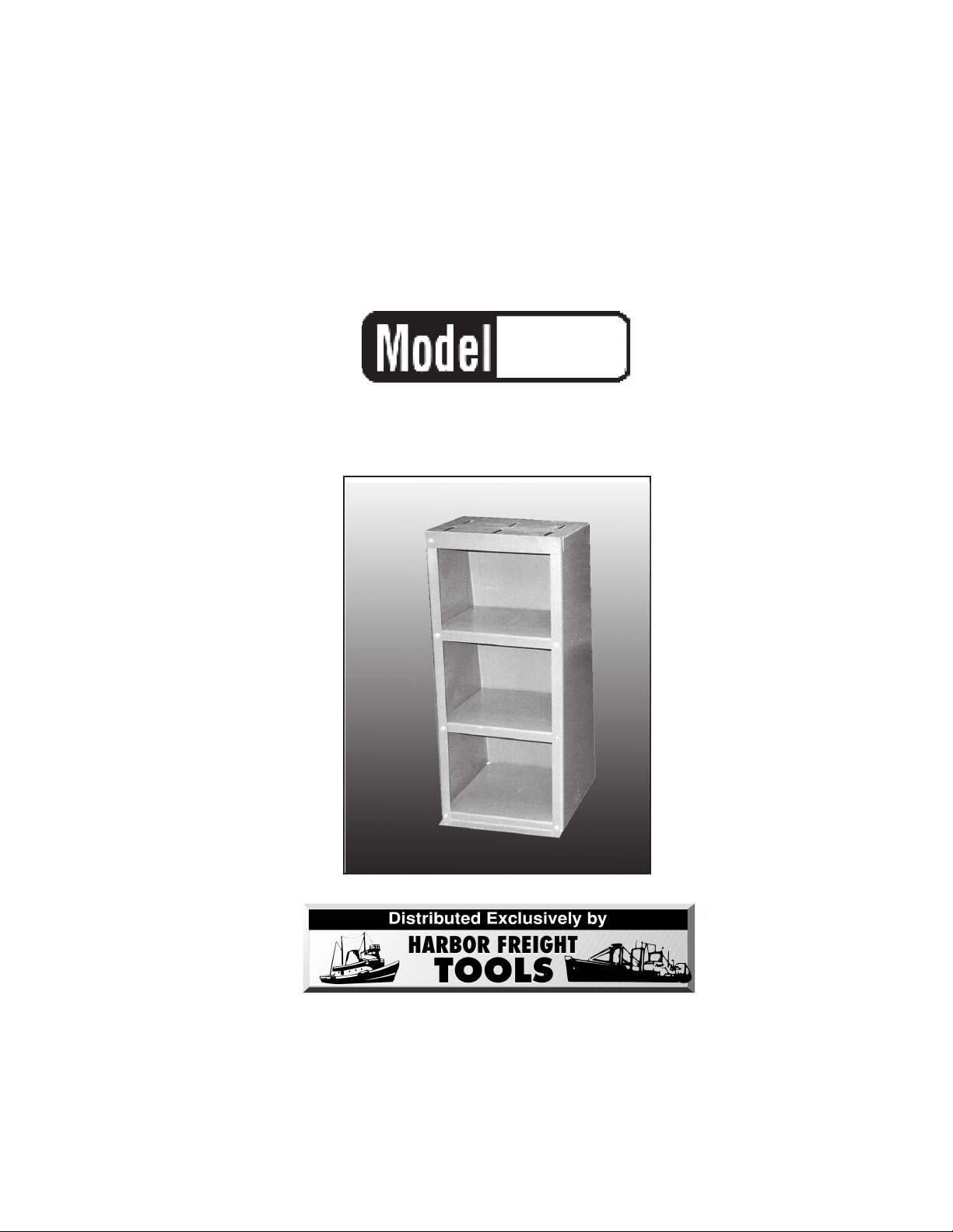
GRINDER/BUFFER
®
CABINET
40089
OPERATING INSTRUCTIONS
3491 Mission Oaks Blvd., Camarillo, CA 93011
Visit our Web site at http://www.harborfreight.com
Copyright © 2002 by Harbor F reight T ools®. All rights reserved. No portion of this manual
or any artwork contained herein may be reproduced in any shape or form without the
express written consent of Harbor Freight Tools.
For technical questions please call 1-800-444-3353
Page 2

SPECIFICATIONS
ITEM
Body Construction
Finish
Overall Dimensions
Top Mounting Holes
Base Mounting Holes
Lower Shelf
Middle Shelf
Top Shelf
Top Dimensions
Overall Weight
Body: Formed and Stamped Sheet Steel
Black Powder Coat
34-1/4”H X 15-3/4”L X 12-3/8”W
3/8”W X 2-3/4”L (6X Slotted Holes)
308” Dia. (4X)
13-3.8” X 12-3/8”
12-1/8” X 12-3/8”
10-5/8” X 12-3/8”
12-7/8”W X 10”L X 1-7/8”H
47 Lbs.
DESCRIPTION
SAVE THIS MANUAL
You will need the manual for the safety warnings and precautions, assembly
instructions, operating and maintenance pr ocedures, parts list and diagram. K eep your in voice with
this manual. Write the in voice number on the inside of the fr ont cover . K eep the manual and inv oice
in a safe and dry place for future reference.
SAFETY WARNINGS AND PRECA UTIONS
1. KEEP PRODUCT USAGE AREA CLEAN. Cluttered areas invite injuries.
2. KEEP CHILDREN AW AY FROM PRODUCT USA GE AREA. Do not allo w children to climb on this
product or play around tools or supplies.
3. DO NOT USE THIS PRODUCT IF UNDER THE INFLUENCE OF ALCOHOL OR DR UGS. Read
warning labels on prescriptions to determine if your judgement or reflexes are impaired while taking
drugs. If there is any doubt, do not attempt to use this product.
4. ST AY ALERT. Watch what you are doing at all times . Use common sense. Do not use a Buffer or
Grinder mounted on this product when you are tired or distracted.
5. CHECK FOR DAMA GED PARTS. Before using this product, carefully check that it will oper ate properly
and perform its intended function. Chec k f or damaged parts and any other conditions that may aff ect
its operation. Replace or repair damaged or worn parts immediately.
6. DO NOT MODIFY THIS PRODUCT . T his product is designed to support a Grinder or Buffer. Do
not modify this Cabinet in an attempt to use it for other purposes.
7. REPLACEMENT P AR TS AND ACCESSORIES. When servicing, use only identical replacement
parts. Only use accessories intended for use with this product. Approved accessories are
available from Harbor F reight T ools.
8. USE THIS PRODUCT only for its intended use, as described in this manual. Do not use
attachments or modify it in any way.
9. BE SURE to use proper hardware (not included) to secure Grinder or Buffer .
NO TE : Always read and adhere to all warnings and instructions provided in the instruction manual of the buffer
or grinder being used.
WARNING: The warnings, cautions and instructions discussed in this instruction manual cannot cover all
possible conditions and situations that may occur . It must be understood by the operator that common sense
and caution are factors which cannot be built into this product, b ut must be supplied by the oper ator .
SKU 40089 PAGE 2
Page 3

UNP ACKING
When unpacking, check to make sure all parts shown on the P arts List (page 4) are included. If any parts are
missing or broken, please call Harbor F reight Tools at the number shown on the cover of this manual as soon
as possible.
ASSEMBLY INSTRUCTIONS
NOTE: All parts below refer to the parts listed on page 4 of this manual.
Assembly
1. To assemble Steel Grinding/Buffing Cabinet with three storage shelves you must first lay out all parts and
hardware on a clean surface.
2. Identify the Top Shelf (#6), the two Side Panels (#2A, #2B, right and left), the Base (#1), and the
Back Panel (#5).
#9, #8, #7
#2A
#2B
#5
#1
3. Starting with the Base (#1), fit the side panels over the Base, lining up the holes. Use the Bolt (#9) through
the holes. Secure with Washer (#8) and Nut (#7). Repeat with Side Panels (#2A & #2B). Attach Back Panel
(#5) to Side Panels and Base in the same way.
4. Slide in Shelves (larger on bottom and graduating up to smallest) (C & D). Secure each shelf with Bolts (#9),
Washers (#8) and Nuts (#7) to Side Panels and Back Panel.
#D
#6
#C
5. Attach Top (#6) aligning with remaining holes. With Bolt (#9) through the holes, secure with Washer (#8) and
Nut (#7) through front and back of Cabinet.
6. Choose where you want to place Cabinet permanently. Anchor through holes in Base (#1) with hardware for
cement or wood flooring, depending on where you choose to mount Cabinet so it is secure during Grinding
or Buffing for a strong sturdy work surface. (Hardware not included.)
7. Attach your Buffer or Grinder through the 6 top mounting holes (3/8” H X 2-3/4” L). Hardware will be
required (not supplied). A non flammable rubber pad (not supplied) for insulation, is recommended between
the Cabinet Top and the Buffer or Grinder. This pad will help reduce vibration.
SKU 40089 PAGE 3
Page 4

PART # DESCRIPTION QTY
1
2A
2B
C
D
5
6
7
8
9
Base
Left Side
Right Side
(larger) Shelf
(smaller) Shelf
Back Panel
Top (with sloted holes)
Nut (10MM)
Washer
Bolt (M6 X 1,00MM Round Flat)
1
1
1
1
1
1
1
16
16
16
(#6)
(#5)
(#2B)
(D)
(#7)
(#8)
(#9)
(C)
(#2A)
(#1)
MAINTENANCE
1. For better and safer performance, keep all parts of this product clean and dry at
all times.
PLEASE READ THE FOLLOWING CAREFULLY
THE MANUF ACTURER AND/OR DISTRIBUT OR HAS PROVIDED THE P ARTS DIA GRAM IN THIS MANU AL
AS A REFERENCE TOOL ONLY. NEITHER THE MANUFACTURER NOR DISTRIBUTOR MAKES ANY
REPRESENT ATION OR W ARRANTY OF ANY KIND TO THE BUYER THAT HE OR SHE IS QU ALIFIED T O
MAKE ANY REPAIRS TO THE PRODUCT OR THAT HE OR SHE IS QUALIFIED TO REPLACE ANY
P ARTS OF THE PRODUCT . IN F ACT , THE MANUF ACTURER AND/OR DISTRIBUT OR EXPRESSL Y ST A T ES
THAT ALL REPAIRS AND PARTS REPLACEMENTS SHOULD BE UNDERTAKEN BY CERTIFIED AND
LICENSED TECHNICIANS AND NO T BY THE BUYER. THE BUYER ASSUMES ALL RISK AND LIABILITY ARISING OUT OF HIS OR HER REP AIRS TO THE ORIGINAL PRODUCT OR REPLACEMENT PARTS
THERETO, OR ARISING OUT OF HIS OR HER INSTALLATION OF REPLACEMENT PARTS THERETO .
SKU 40089 PAGE 4 REV 03/05
 Loading...