

Page 1
Instruction Manual
LP2000-11
Precision Bench
Turbidity Meter
with PC Communication
www.hannainst.com
Page 2

Dear Customer,
Thank you for choosing a Hanna Product. Please read this instruction
manual carefully before using the instrument. It will provide you with
the necessary information for the correct use of the instrument, as well
as a precise idea of its versatility.
If you need additional technical information, do not hesitate to e-mail
us at tech@hannainst.com.
These instruments are in compliance with the directives.
PRELIMINARY EXAMINATION
Remove the instrument from the packing material and examine it to make
sure that no damage has occurred during shipping. If there is any
damage, notify your Dealer.
LP2000-11 is supplied with:
• Glass cuvet with cap
• AMCO-EPA-1 turbidity calibration solutions (HI 93703-0 @0 FTU
and HI 93703-10 @10 FTU), 30 mL each
• 12 Vdc power adapter and instruction manual
Note: Save all packing material until you are sure that the instrument
functions correctly. Any defective item must be returned in its
original packaging with the supplied accessories.
TABLE OF CONTENTS
Preliminary Examination ............................................................. 3
General Description ..................................................................... 3
Principle of Operation ................................................................. 4
Specifications.............................................................................. 5
Functional Description ................................................................. 6
Operational Guide ...................................................................... 7
Power Connection ........................................................ 7
Measurement Procedure ...................................................... 7
Storing samples in memory ................................................ 10
Clearing Logged Data........................................................ 10
Viewing Logged Data ........................................................ 11
Date and Time setup ......................................................... 11
Error Codes ....................................................................... 12
Ensure Accurate Measurements ........................................... 13
Sources of Interference ....................................................... 14
Calibration............................................................................... 14
Calibration Procedure ........................................................ 14
Viewing Calibration Date ................................................... 16
Ensure Accurate Calibration ................................................ 17
Standard Suspension ........................................................ 17
RS 232 Connection ................................................................... 18
Accessories ................................................................................ 18
Warranty................................................................................. 19
GENERAL DESCRIPTION
LP2000-11 turbidity meter is a bench top, microprocessor-based instrument
used to determine the turbidity of water and wastewater. The meter covers
a 0-1000 FTU range in two scales: 0.00 to 50.00 FTU and 50 to 1000
FTU. The autoranging feature sets the appropriate range for the
measurement.
The serial interface is supported connecting any available serial port on
your PC and a 5-pin socket on the meter.
Note: LP2000-11 has been designed according to the ISO 7027
International Standard, consequently the turbidity
measurement units are expressed in FTU (Formazine Turbidity
Unit). FTU is identical to the other internationally recognized
unit NTU (Nephelometric Turbidity Unit).
LP2000-11 is housed in a rugged and lightweight case, with an
easy-to-read LCD.
The meter is simply to use. All operations can be carried out with only
five keys and troubleshooting functions can be performed with
displayed error code guides. A positive-locking system guarantees that
the cuvet is firmly placed in the cell. The keypad is water-resistant
and can be wiped with a moist cloth for quick cleanups.
Two or three points calibration (0, 10, 500 FTU*) can be easily
performed using available standards.
* 1 FTU = 1 NTU
32
Page 3
CUVET
LIGHT
D
In addition, LP2000-11 automatically stores the last calibration
date, that may be retrieved by a single key touch.
10 FTU* was chosen as the standard calibration point because its
value best fits the water turbidity measurements in a wide range of
applications, from drinking water to wastewater treatment.
Hanna uses the primary standard AMCO-AEPA-1 to avoid all formazinerelated problems. In fact formazine is a toxic, unstable substance, which
requires particular care. Its standards have to be prepared only a few
minutes before performing the calibration, and cannot be reused because
of their short life.
Hanna standards are extremely stable, can be reused, and last up to six
months, if free from contaminations.
LP2000-11 can be used with both standards.
As noted above, FTU is equal to the NTU. However, other known
measurements include: Jackson Turbidity Unit or JTU (based on the
old method of Jackson's candle), and Silica Unit in mg/L of SiO2.
See the conversion table below for these units:
JTU FTU/NTU SiO2 (mg/L)
JTU 1 19 2.5
FTU /NTU 0.053 1 0.13
SiO2 (mg / L) 0.4 7.5 1
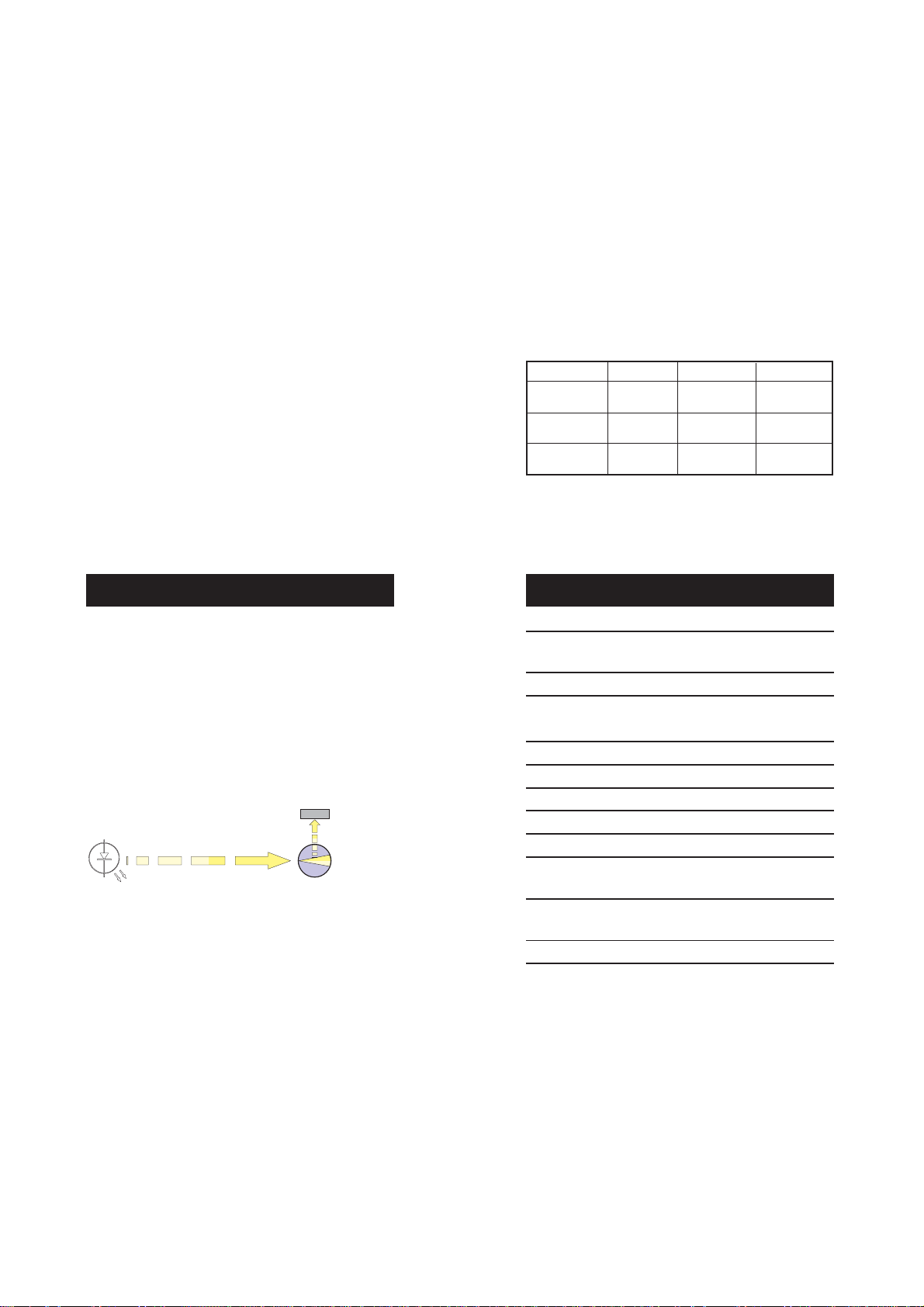
PRINCIPLE OF OPERATION
LP2000-11 has been designed to perform measurements according
to the ISO 7027 International Standards.
The instrument works by passing a beam of infrared light through a
vial containing the sample to be measured.
The light source is a High Emission Infrared LED with a wavelength
peaking at 890 nm, which reduces interferences caused by colored
samples to a minimum.
DETECTOR
IR LED
EMITTED LIGHT (890 nm)
A sensor, positioned at 90° with respect to the direction of light,
detects the amount of light scattered by the undissolved particles
present in the sample. The microprocessor converts such readings into
FTU values.
90° SCATTERE
LIGHT
SPECIFICATIONS
Range 0.00 to 50.00 FTU*
50 to 1000 FTU*
Resolution 0.01 / 1 FTU*
Accuracy (@ 20°C/68°F) ±0.5 FTU*
±5% of reading (whichever greater)
Calibration 3 points (0, 10 and 500 FTU*)
Light Source High-emission infrared LED
Light Source Life Life of the instrument
Light Detector Silicon photocell
Power Supply 12 Vdc power adapter (included)
Environment 0 to 50°C (32 to 122°F);
RH max 95% non-condensing
Dimensions 230 x 170 x 70 mm
(9.1 x 6.7 x 2.7")
Weight 600 g (1.3 lb.)
* 1 FTU = 1 NTU* 1 FTU = 1 NTU
54
Page 4
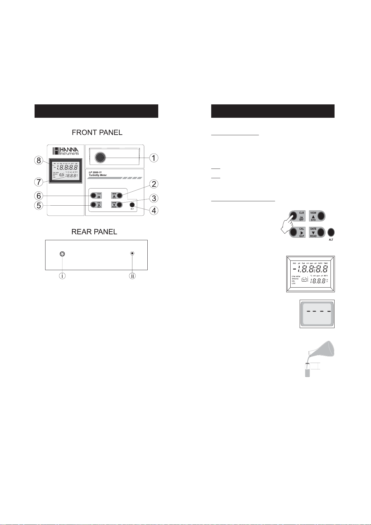
FUNCTIONAL DESCRIPTION
OPERATIONAL GUIDE
POWER CONNECTION
Plug the supplied 12 Vdc adapter into the proper instrument socket
and to the mains.
Note: Insure the main line is fuse protected.
Note: Always turn the meter off before unplugging it to ensure no
data is lost.
MEASUREMENT PROCEDURE
• Turn the meter on by pressing
the ON/OFF key.
• The meter will carry out a self-test
by displaying a full set of figures.
1. Measurement cell
2. STO/VIW key, to store sample after reading and view log memory
3. READ/DATE key, to perform measurements and display (toggle)
current date/time
4. ALT key, to activate the ALT functions (orange keys)
5. GLP/CAL key, to display (toggle) last calibration date/time and
enter the calibration mode
6. ON/OFF/CLR key to switch the meter ON and OFF, and clear log
memory
7. Secondary LCD (displays the year when date is on the primary level,
the sample index when storing a value or viewing the log memory)
8. Primary LCD (Liquid Crystal Display)
i. 5-pin RS232 connector
ii. Power supply socket
• When the LCD displays “- - --” the
meter is ready to take measurements.
• Fill a clean cuvet up to 0.5 cm
(one quarter inch) from its rim
with the thoroughly agitated
sample.
1/4“
0.5 cm
• Allow sufficient time for bubbles to escape before securing the cap.
Note: Do not overtighten the cap.
76
Page 5

Note: Wipe the cuvet thoroughly with
HI93703-70 or a lint-free tissue before
inserting it into the measurement cell.
The cuvet must be completely free of
fingerprints and other oil or dirt, particularly in the area where the light goes
through (approx. the bottom 2 cm/1").
• Place the cuvet into the cell and
check that the notch on the cap is
positioned securely into the groove.
• The mark on the cuvet cap should point
towards the keyboard.
• Even though LP2000-11 covers a wide turbidity range, highly
accurate readings exceeding 40 FTU* require dilution as recommended by the Standard Methods.
Use the formula below to calculate the amount of HI 93703-0 or
turbidity-free water needed for accurate dilution.
The total volume = 100 mL.
Vos = 3000 / T
where:
Vos = volume of original sample (mL) to be added to HI 93703-0
to obtain the total diluted volume of 100 mL.
T = LP2000-11 reading (exceeding 40 FTU)
E.g.: LP2000-11 reading = 200 FTU*
3000 / 200 = 15 mL (Vos)
15 mL (Vos)+85 mL (HI 93703-0) = 100 mL
At this point, take a sample of this diluted solution and measure its
turbidity.
The correct turbidity value of the original sample is derived by:
Ta= Tn x 100 mL / Vos
where:
Ta = actual turbidity value of the original sample
Tn = LP2000-11 reading of the diluted solution
E.g. If Tn = 27
Ta = 27 x 100 mL / 15 mL = 180 FTU*
• Press the READ key and the LCD will
display a blinking “SIP” (Sampling in Process). The turbidity
value will appear after approximately 20 seconds.
Note: Any sample above 1000 FTU* will show out of range by blinking
“1000”.
* 1 FTU = 1 NTU
98
Page 6

STORING SAMPLES IN MEMORY
VIEWING LOGGED DATA
• After taking a reading, press the STO
button. The last sample read will be
stored in memory and the display will
also show on the bottom right hand
corner the reference number of the
stored sample.
Note: When the maximum number of
samples has been reached (500), the
display will show "FULL". This is a warning that you will be overwriting the oldest
sample recorded. To store the current
sample, press the STO button again and
this will overwrite the oldest sample in the
memory. All samples are shifted and
sample number one is always the oldest
sample.
CLEARING LOGGED DATA
• Press the ALT & CLR buttons. The display will show
"CLR" for confirmation.
Press ALT & CLR again to
clear memory or any other
key to abort the operation.
• Press the ALT & VIEW buttons. The last stored sample
will be displayed.
• Press the right arrow to
scroll between turbidity
value, date and time
sample was taken.
• Press the UP/DOWN arrows
to scroll between samples
taken.
• Press ALT & VIEW buttons again to exit this mode.
DATE AND TIME SETUP
VIEWING:
• Press ALT & DATE to toggle
between date and time.
SETTING:
• Press and hold ALT & DATE for
3-4 seconds.
ALL SAMPLES PREVIOUSLY STORED WILL BE ERASED FROM
MEMORY!
• Press UP/DOWN arrows to correct and set the year.
1110
Page 7

• Press right arrow to scroll to month and day, use UP/DOWN to set.
• Press right arrow again to scroll to time, use UP/DOWN to set.
• Internal Bus error*
err5
• Press right arrow again to save and exit date and time setup.
Note: Press ALT & DATE to leave this mode without saving.
ERROR CODES
Every time the meter is switched on, the Real Time Clock and EEPROM are
tested, and if an error is found the corresponding error code will be
displayed. The list of error codes is as follows:
• NO cover error (check cuvet position)
• Calibration error
(check calibration standard value)
cap
err1
err2
• RTC (Real Time Clock) error *
• EEPROM error*
err3
• Low LED Voltage*
* Contact the nearest HANNA Customer Service Center.
ENSURE ACCURATE MEASUREMENTS
• Each time the cuvet is used, tighten the cap to the same degree.
• Discard the sample immediately after reading to prevent permanent clouding of the glass.
• All glassware used to contain the standards and the samples
should be kept clean, washed with HI93703-50 cleaning solution
and rinsed with HI93703-0 or turbidity-free water.
• Samples should be collected in clean glass or plastic bottles with
appropriate stoppers. Analysis should be performed shortly after.
If the sample requires storage, it should be kept in a cool dark
place. Stored samples should be restored to room temperature
prior to the analysis. Samples may not be stored for longer than
24 hours.
• To obtain a representative sample, gently and thoroughly, stir
the solution. To prevent air bubbles from forming do not shake or
let the solution settle prior to sampling.
• It is recommended to calibrate the meter by using the supplied
HI93703-10 (10 FTU* standard), at least monthly or more
frequently for greater accuracy.
• Before inserting cuvets into the instrument, wipe them with
HI 93703-70 or a soft, lint-free tissue. Handle vials so that no
fingerprints are left on the areas where light passes through
(approx. the bottom 2cm / 3/4”).
• Serial communication error*
err4
If you experience any problems in taking measurements, please
contact your dealer or the nearest Hanna Customer Service Center.
1312
Page 8

SOURCES OF INTERFERENCE
• The presence of floating debris and coarse sediments which may
settle out rapidly will give false readings.
• The infrared light source of LP2000-11 turbidity meter complies
with the ISO 7027 International Standard and can effectively
minimize errors due to colored dissolved substances. This effect,
called “True Color”, is a common interference for most commercially
available instruments operating in the range of visible light.
• Air bubbles and the effect of vibrations that disturb the surface of
the sample may produce false results and should be avoided.
• Dirty, scratched, or etched glassware could also affect readings.
• Place the 0.00 FTU standard in the cuvet
holder.
• Press CAL; SIP and CL will start blinking.
CALIBRATION
To check the date of last calibration, simply press the GLP key. Press again
to toggle between date and time.
To make sure that the meter is calibrated, take a measurement of a
standard solution.
The instrument can be calibrated at two or three points and a monthly
calibration is recommended.
CALIBRATION PROCEDURE
• Turn the meter on and wait for the display
to show "----".
• Press the ALT & CAL buttons. The "CAL" message will blink on the display
for 3 seconds. The meter then enters the calibration mode, displaying
"0.00" and prompting the user to insert the 0.00 FTU standard.
• If “ERR1” appears on the LCD, please check
the standard solution.
• After approximately 30 seconds the meter
will display “10.00”, prompting the user
to place the 10.00 FTU standard solution
in the cuvet holder.
• Place the 10.00 FTU standard in the
holder and press CAL. SIP and CL will start
blinking.
• After approximately 30 seconds the meter
will display 500, asking the user to place
the 500 FTU standard solution in the cuvet
holder.
Note: At this point the user can save the two-point calibration setup
and leave the calibration mode by pressing ALT & CAL buttons.
err1
1514
Page 9

To perform a three point calibration, place the
500 FTU standard solution in the cuvet
holder.
• Press CAL; SIP and CL will start blinking.
• After approximately 30 seconds the LCD will
display "----".
Now the instrument is calibrated and ready
for use.
Note: If "ERR1" is displayed, the calibration data is maintained.
ENSURE ACCURATE CALIBRATION
The procedure below should be carefully followed during testing and
calibration:
• All glassware that comes into contact with standards should be kept
clean. Wash it with HI93703-50 cleaning solution and rinse it with
HI93703-0 or turbidity free water.
• Rinse the cuvet twice with 5 ml of the liquid to be tested. This procedure
removes the effect of any previous liquid and any dust or objects that
may be inside. Gently pour the liquid down the side of the vial to reduce
air bubbles (no mixing is required when HI93703-0 and HI93703-
10 AMCO-AEPA-1 standards are used).
• Before inserting the cuvet into the instrument, wipe it with HI 9370370 or a soft, lint-free tissue. Handle vials so that no fingerprints can
get on the areas where light passes (approx. bottom 2 cm/1") .
STANDARD SUSPENSION
VIEWING CALIBRATION DATE
To display the last calibration time and date, press the GLP button. If
display shows "FS", the instrument has factory calibration settings loaded
and no date will be displayed.
VIEWING FIRMWARE VERSION
To display the firmware version, turn the meter on, then press and hold
the ON/OFF key for approximately 10 seconds.
Presently, there are only two recognized primary standards: AMCO-AEPA1 and formazine.
Hanna supplies LP2000-11 with the AMCO-AEPA-1 which has a much
longer shelf life at all concentrations (approx. six months, if free from
contamination). In addition, no special handling or disposal is required
and a much higher stability of suspended particles has been observed.
On the other hand, formazine is a toxic substance, generated by a
carcinogen, with poor stability (particles flocculate and settle quickly). Low
concentrations change value within a few days or hours after dilution.
The consistency of LP2000-11 readings by using both standards has been
separately established by Advanced Polymer Systems and Hanna
Instruments.
Additional documentation about the formazine standard and more
complex calibration procedures is available upon request.
1716
Page 10

RS232 CONNECTION
WARRANTY
To communicate with the instrument through the HI92000 software,
simply use HI920011 (optional) cable to connect the 9-pin serial port of
an IBM compatible computer and the 5 pin connector of the meter.
A connected meter will fully maintain its functionality, being able to perform
data transfer while the meter is operating.
Note: RS232 communication is not allowed while calibrating the meter.
ACCESSORIES
HI 710005 12 Vdc / 115 Vac power adapter, US plug
HI 710006 12 Vdc / 230 Vac power adapter, European plug
HI 731318 Tissue for wiping the cuvets (4 pcs)
HI 731321 Glass cuvet (4 pcs)
HI 93703-0 0 FTU* AMCO-AEPA-1 calibration solution
(30 mL)
HI 93703-05 500 FTU* AMCO-AEPA-1 calibration solution
(30 mL)
HI 93703-10 10 FTU* AMCO-AEPA-1 calibration solution
(30 mL)
HI 93703-50 Cuvet cleaning solution (230 mL)
HI 92000 Windows® compatible software
HI 920011 PC connection serial cable (5 to 9-pin)
All Hanna Instruments meters are warranted for two years
against defects in workmanship and materials when used for their
intended purpose and maintained according to instructions. This
warranty is limited to repair or replacement free of charge.
Damage due to accident, misuse, tampering or lack of prescribed
maintenance are not covered.
If service is required, contact the dealer from whom you purchased
the instrument. If under warranty, report the model number, date of
purchase, serial number and the nature of the failure. If the repair
is not covered by the warranty, you will be notified of the charges
incurred. If the instrument is to be returned to Hanna Instruments,
first obtain a Returned Goods Authorization number from the Customer Service department and then send it with shipping costs
prepaid. When shipping any instrument, make sure it is properly
packaged for complete protection.
Hanna Instruments reserves the right to modify the design, construction and appearance of its products without advance notice.
* 1 FTU = 1 NTU
Recommendations for Users
Before using this product, make sure that it is entirely suitable for the environment
in which it is used.
Operation of this instrument in residential area could cause unacceptable
interferences to radio and TV equipments, requiring the operator to take all necessary
steps to correct interferences.
Any variation introduced by the user to the supplied equipment may degrade the
instrument's EMC performance.
To avoid electrical shock, do not use this instrument when voltages at the
measurement surface exceed 24VAC or 60VDC.
To avoid damages or burns, do not perform any measurement in microwave ovens.
1918
Page 11

SALES AND TECHNICAL SERVICE CONTACTS
Australia:
Tel. (03) 9769.0666 • Fax (03) 9769.0699
China:
Tel. (10) 88570068 • Fax (10) 88570060
Egypt:
Tel. & Fax (02) 2758.683
Germany:
Tel. (07851) 9129-0 • Fax (07851) 9129-99
Greece:
Tel. (210) 823.5192 • Fax (210) 884.0210
Indonesia:
Tel. (21) 4584.2941 • Fax (21) 4584.2942
Japan:
Tel. (03) 3258.9565 • Fax (03) 3258.9567
Korea:
Tel. (02) 2278.5147 • Fax (02) 2264.1729
Malaysia:
Tel. (603) 5638.9940 • Fax (603) 5638.9829
Singapore:
Tel. 6296.7118 • Fax 6291.6906
South Africa:
Tel. (011) 615.6076 • Fax (011) 615.8582
Taiwan:
Tel. 886.2.2739.3014 • Fax 886.2.2739.2983
Thailand:
Tel. 66.2619.0708 • Fax 66.2619.0061
United Kingdom:
Tel. (01525) 850.855 • Fax (01525) 853.668
USA:
Tel. (401) 765.7500 • Fax (401) 765.7575
For e-mail contacts and complete list of Sales and
Technical offices, please see www.hannainst.com
20
MANLP2000-11 11/05
 Loading...