

Page 1
Instruction Manual
HI 98186
Dissolved Oxygen
BOD/OUR/SOUR
Meter
HI 98186
Dissolved Oxygen Meter
www.hannainst.com
1
Page 2

Dear Customer,
Thank you for choosing a Hanna Instruments product.
Please read this instruction manual carefully before using the instrument.
This manual will provide you with the necessary information for correct use of
the instrument, as well as a precise idea of its versatility.
If you need additional technical information, do not hesitate to e-mail us at
tech@hannainst.com or turn to the back cover for our worldwide contact list.
These instruments are in compliance with directives.
WARRANTYWARRANTY
WARRANTY
WARRANTYWARRANTY
The HI 98186 instrument is guaranteed for two years against defects in
workmanship and materials when used for its intended purpose and maintained
according to instructions. Electrodes and probes are guaranteed for six months.
This warranty is limited to repair or replacement free of charge.
Damage due to accidents, misuse, tampering or lack of prescribed maintenance
is not covered.
If service is required, contact the dealer from whom you purchased the
instrument. If under warranty, report the model number, date of purchase,
serial number and the nature of the problem. If the repair is not covered by
the warranty, you will be notified of the charges incurred. If the instrument is
to be returned to Hanna Instruments, first obtain a Returned Goods Authorization number from the Technical Service department and then send it with
shipping costs prepaid. When shipping any instrument, make sure it is
properly packed for complete protection.
2
Page 3

TABLE OF CONTENTSTABLE OF CONTENTS
TABLE OF CONTENTS
TABLE OF CONTENTSTABLE OF CONTENTS
WARRANTY ......................................................................................... 2
PRELIMINARY EXAMINATION ................................................................ 4
GENERAL DESCRIPTION ........................................................................ 4
FUNCTIONAL DESCRIPTION .................................................................. 6
SPECIFICATIONS.................................................................................. 8
PROBE FUNCTIONAL DESCRIPTION ....................................................... 9
PROBE CONNECTION AND PREPARATION............................................. 10
OPERATIONAL GUIDE......................................................................... 11
OUR MEASUREMENT ......................................................................... 21
SOUR MEASUREMENT ....................................................................... 24
TEMPERATURE MEASUREMENT ............................................................ 27
DO CALIBRATION PROCEDURE ............................................................ 27
GOOD LABORATORY PRACTICE (GLP) ................................................... 32
SETUP .............................................................................................. 33
LOGGING .......................................................................................... 45
AutoEnd ........................................................................................... 48
PRESSURE CALIBRATION .................................................................... 49
TEMPERATURE CALIBRATION .............................................................. 51
PC INTERFACE ................................................................................... 54
BATTERY RECHARGER/REPLACEMENT .................................................... 62
PROBE MAINTENANCE ....................................................................... 64
TROUBLESHOOTING GUIDE ................................................................ 65
ACCESSORIES .................................................................................... 66
3
Page 4

PRELIMINARY EXAMINATIONPRELIMINARY EXAMINATION
PRELIMINARY EXAMINATION
PRELIMINARY EXAMINATIONPRELIMINARY EXAMINATION
Remove the instrument from the packing material and examine it carefully to
make sure that no damage has occurred during shipping. If there is any
damage, notify your Dealer or the nearest Hanna Customer Service Center.
Each instrument is supplied with:
• HI 76407/4F Polarographic probe with built-in temperature sensors and
4 m (13.4”) cable
• HI 76407A Membrane cap (2 pcs)
• HI 7041S Electrolyte solution (30 mL)
• 4 x 1.2V AA, 1300 mAh Rechargeable Batteries (inside the instrument)
• HI 710042 Inductive Recharger with power adaptor
• Instruction Manual
• Rugged carrying case
Note: Save all packing material until you are sure that the instrument
functions correctly. All defective items must be returned in the original
packing with the supplied accessories.
GENERAL DESCRIPTIONGENERAL DESCRIPTION
GENERAL DESCRIPTION
GENERAL DESCRIPTIONGENERAL DESCRIPTION
The HI 98186 is a state of art, microprocessor based, dissolved oxygen
instrument with many automated and specific application features, designed
to provide laboratory results and accuracy under harsh industrial conditions.
All measurements are automatically compensated for temperature. Salinity
compensation in water allows direct determination of dissolved oxygen in
saline waters. With its internal barometer, the instrument is able to automatically compensate for changes in barometric pressure so there is no need for
charts, altitude information or external barometric pressure information.
The instrument contains built-in application software for the calculation of
Biochemical Oxygen Demand (BOD), Oxygen Uptake Rate (OUR) and Specific
Oxygen Uptake Rate (SOUR).
HI 98186’s calibration has been greatly simplified when compared to other
dissolved oxygen instruments. It is provided with a series of new features which
add entirely new dimensions to the measurement of DO, by allowing the user
to dramatically improve the reliability of the measurement:
• One or two points automatic dissolved oxygen calibration.
• One point manual dissolved oxygen calibration using a value in milligrams
per liter or percent saturation entered by the user.
• One or two points user temperature calibration.
• Messages on the graphic LCD for an easy and accurate calibration.
• User-selectable “calibration time out” to remind when a new calibration is
necessary.
4
Page 5

Moreover, the meter offers an extended temperature range from
–20 ºC to 120 ºC (–4 ºF to 248 ºF).
Other features include:
• Log on demand up to 400 samples.
• Auto Hold feature, to freeze first stable reading on the LCD.
• GLP feature, to view last calibration data.
• PC interface.
Hanna Instruments reserves the right to modify the design,
construction and appearance of its products without advance notice.
5
Page 6
Front viewFront view
Front view
Front viewFront view
FUNCTIONAL DESCRIPTIONFUNCTIONAL DESCRIPTION
FUNCTIONAL DESCRIPTION
FUNCTIONAL DESCRIPTIONFUNCTIONAL DESCRIPTION
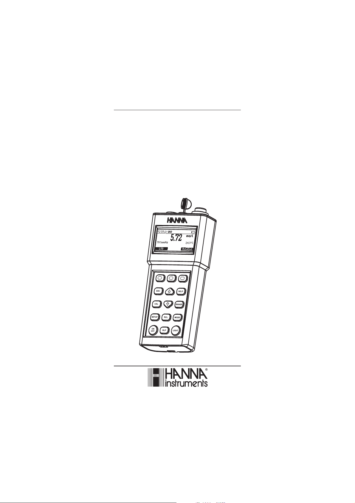
1) Liquid Crystal Display (LCD).
2) F1, F2, F3 functional keys.
/ keys to manually increase/decrease the parameters or to scroll the pa-
3)
rameter list.
4) ESC key to leave current mode, exit calibration, setup, help, etc.
5) CAL key, to enter/exit calibration mode.
6) RCL key, to enter/exit view logged data mode.
7) SETUP key, to enter/exit SETUP mode.
8) ON/OFF key, to turn the instrument ON and OFF.
9) GLP key, to display Good Laboratory Practice information.
10) LIGHT key, to toggle display backlighting.
11) MODE key to change DO measuring unit when in DO measure screen, or to
toggle between standard and pressure in DO calibration.
12) RANGE key, to switch between DO, BOD, OUR AND SOUR.
13) Help key to enter/exit contextual help.
6
Page 7

Top viewTop view
Top view
Top viewTop view
15
14) Electrode DIN connector.
15) USB connector.
14
DOUSB
7
Page 8
SPECIFICATIONSSPECIFICATIONS
SPECIFICATIONS
SPECIFICATIONSSPECIFICATIONS
EGNAR
NOITULOSER
YCARUCCA
Fº86/Cº02@
noitarbilaCOD
noitarbilacerutarepmeTeulaverutarepmetegnarniynatatniop2ro1
noitarbilacerusserPeulaverusserpegnarniynatatniop1
noitasnepmocerutarepmeT
noitasnepmoCerusserPgHmm058ot054morfcitamotuA
L/gm00.05ot00.0
noitarutas%0.006ot0.0
gHmm058ot054
)Fº0.842ot0.4–(Cº0.021ot0.02–
L/gm10.0
noitarutas%1.0
gHmm1
)Fº1.0(Cº1.0
tigid1±gnidaer%5.1
noitarbilacehtmorf%51±nihtiwgHmm3±
tniop
)Fº4.0±(Cº2.0±
)rorreeborpgnidulcxe(
tanoitarbilaccitamotuastniop2roeno•
.)L/gm0(%0dna)L/gm62.8(%001
ybderetneeulavagnisulaunamtniop1•
.L/gmronoitarutas%niresueht
morfcitamotuA
)Fº0.221ot0.23(Cº0.05ot0.0
noitasnepmoCytinilaSL/g07ot0morfcitamotuA
eborPOD F4/70467IH cihpargoraloP
GOLselpmas004,dnamednO
efiL&epyTyrettaB
regrahceR 240017IH )dedulcni(regrahcerevitcudnI
ffo-otuA
ecafretnICPdetalosi-otpo BSU
snoisnemiD)''2x57.3x9.8(mm25x59x5.622
)ylnoretem(thgieWg525
tnemnorivnE
8
seirettabelbaegrahcerAAV2.1x4
tuohtiwesusuounitnocfosruoh002.xorppa
)thgilkcabhtiwsruoh05(thgilkcab
rosetunim06,03,01,5:elbatcelesresU
delbasid
)Fº221–23(Cº05–0
%001HR.xam
Page 9
PROBE FUNCTIONAL DESCRIPTIONPROBE FUNCTIONAL DESCRIPTION
PROBE FUNCTIONAL DESCRIPTION
PROBE FUNCTIONAL DESCRIPTIONPROBE FUNCTIONAL DESCRIPTION
PROBE FUNCTIONAL DESCRIPTIONPROBE FUNCTIONAL DESCRIPTION
PROBE FUNCTIONAL DESCRIPTION
PROBE FUNCTIONAL DESCRIPTIONPROBE FUNCTIONAL DESCRIPTION
1. D.O. Probe
2. Protective Cap
3. Watertight Shielded Cable
4. Polypropylene Probe Body
5. Temperature Sensor
6. O-Ring Seal
7. Silver Chloride Anode
8. Platinum Cathode (sensor)
9. Oxygen Permeable Teflon® Membrane
10. Membrane Cap
9
Page 10
PROBE CONNECTION AND PREPARATIONPROBE CONNECTION AND PREPARATION
PROBE CONNECTION AND PREPARATION
PROBE CONNECTION AND PREPARATIONPROBE CONNECTION AND PREPARATION
To take measurements, connect the D.O. probe to the meter securely by
aligning the pins with the socket located on the top of the meter, pushing the
plug in and tightening the threaded ring.
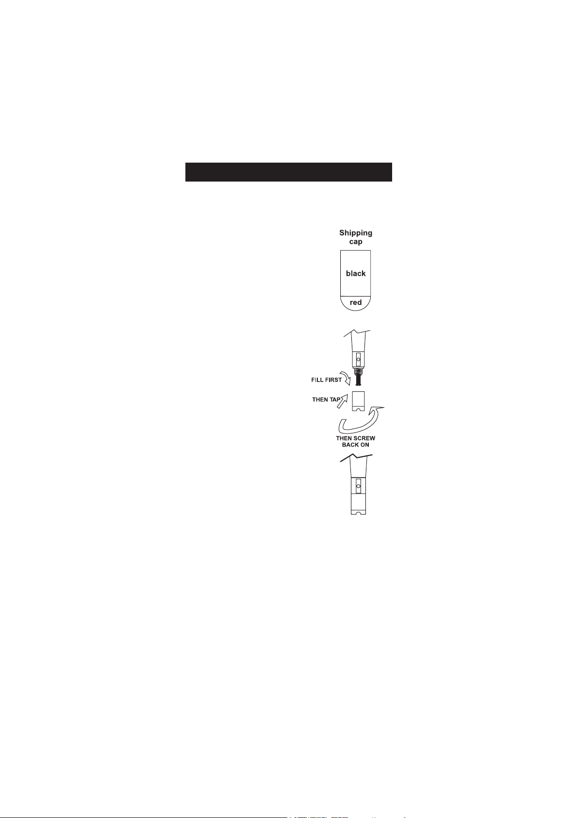
Probes shipped from Hanna Instruments
are dry. To hydrate the probe and prepare
it for use, connect it to the meter and
proceed as follows:
1. Remove the red and black plastic cap.
This cap is for shipping purposes and can
be thrown away.
2. Wet the sensor by soaking the bottom
2½ cm (1") of the probe in electrolyte
(HI 7041S) for 5 minutes.
3. Rinse the membrane cap (HI 76407A)
supplied in the kit with the meter) with
electrolyte solution while shaking it gently.
Refill with clean electrolyte solution.
4. Tap gently the sides of the membrane
cap with your finger tip to ensure that no
air bubbles are trapped. To avoid damaging the membrane, do not tap it directly
on the bottom.
5. Make sure that the rubber O-ring sits
properly inside the membrane cap.
6. With the sensor facing down, slowly
screw the cap clockwise. Some electrolyte
will overflow.
When not in use and during polarization
(see PROBE CONDITIONING page 11), use the protective transparent cap
supplied in the kit with the meter.
10
Page 11

OPERATIONAL GUIDEOPERATIONAL GUIDE
OPERATIONAL GUIDE
OPERATIONAL GUIDEOPERATIONAL GUIDE
INITIAL PREPARATION
The instrument is supplied complete with rechargeable batteries. Proceed with
a complete charging process before starting (see page 60).
To prepare the instrument for field measurements close the serial communication socket and all unused connector sockets with proper stopper (to ensure
waterproof protection).
Connect the DO probe to the 7-pin connector. Make sure that the probe sleeve
is properly inserted and tighten the threaded ring.
Turn the instrument ON by pressing ON/OFF key.
At start-up the display will show the Hanna logo for a few seconds , followed by
the percentage indication of the remaining battery charge, then enters the
probe conditioning mode. The probe will be conditioned for one minute, and
afterwards the instrument will enter measurement mode.
If the DO probe is not connected or is damaged, the conditioning period is
skipped.
To save battery life, the auto-off feature turns the instrument off after a set
period (default 30 min) if no button is pressed. To set another period or to
disable this feature, see SETUP menu on page 33.
The auto-off backlight feature turns the backlight off after a set period (default
1 min) with no buttons pressed. To set another period or to disable this
feature, see SETUP on page 33.
PROBE CONDITIONING
At startup, the probe is under polarization with a fixed voltage of approximately 800 mV for 1 minute.
Probe polarization is essential for stable measurements with the same recurring degree of accuracy.
With the probe properly polarized, oxygen is continually consumed when it
passes through the sensitive diaphragm and dissolves in the electrolyte solution contained in the probe.
Whenever measurements are taken with a non-polarized probe, the oxygen
level revealed is both that of the tested solution, as well as that present in the
electrolyte solution. This reading is incorrect.
Keep the protective cap on during polarization time and remove it for calibration and measurements.
11
Page 12
SALINITY COMPENSATION
If the sample contains significant concentration of salinity, the read out values
must be corrected, taking into account the lower degree of oxygen solubility in
this situation.
Before taking any DO measurements remember to set the salinity value from
the SETUP menu (page 33).
The salinity affects the D.O. concentration, decreasing its value. The table below
shows the maximum oxygen solubility at various temperatures and salinity levels.
Cº
l/g0l/g01l/g02l/g03l/g53
006.4146.3147.2109.1105.110.23
218.3119.2170.2192.1119.015.63
490.3152.2174.1137.0183.012.93
644.2156.1119.0122.0198.98.24
838.1190.1104.0157.944.94.64
0182.1185.0139.923.930.90.05
2177.0111.0105.929.856.86.35
4192.0186.901.955.803.82.75
6168.982.937.812.879.78.06
8154.909.893.809.766.74.46
0280.965.870.806.783.70.86
2237.832.877.733.721.76.17
4204.839.794.770.778.62.57
5242.897.763.759.657.60.77
6290.856.732.738.646.68.87
8218.783.789.616.624.64.28
0345.741.757.693.622.60.68
2392.709.645.691.630.66.98
4350.786.633.610.658.52.39
6328.674.641.638.586.58.69
8316.682.669.566.515.54.001
0414.690.697.505.563.50.401
2422.639.536.553.522.56.701
4440.677.584.512.590.52.111
6478.516.533.570.579.48.411
8407.574.502.559.458.44.811
0545.533.570.538.457.40.221
leveLaeSta)l/g(ytinilaS
Fº
NoteNote
Note: The relationship between salinity and chlorinity for sea water is given by the equation
NoteNote
below:
Salinity (g/l) = 1.80655 Chlorinity (g/l)
12
Page 13

BAROMETRIC PRESSURE COMPENSATION
The dissolved oxygen saturation value varies with pressure, so it is important
to compensate the effect that pressure has on DO measurements.
leveLaeSevobasreteM,edutitlA
Cº
0m003m006m009m0021m0051m0081m0012m0042m0072m0003m0033m0063m0093m0004
06.411.416.311.316.211.217.112.118.014.010.017.93.90.99.80.23
28.313.318.214.219.115.110.116.012.019.95.92.98.85.84.86.53
41.316.212.217.113.119.015.011.017.93.90.97.84.80.89.72.93
64.210.215.111.117.013.019.96.92.99.86.82.89.76.75.78.24
88.114.110.116.012.018.95.91.98.84.81.88.75.73.72.74.64
013.119.015.011.017.94.90.97.84.81.88.75.72.79.68.60.05
218.014.010.016.93.99.86.83.80.87.74.71.79.66.65.66.35
413.019.96.92.99.85.82.89.76.74.71.78.66.63.62.62.75
619.95.92.98.85.82.89.76.73.70.78.65.63.61.60.68.06
815.91.98.85.81.88.76.73.70.78.65.63.60.68.57.54.46
021.98.84.81.88.75.73.70.77.65.62.60.68.56.55.50.86
227.84.81.88.75.72.70.77.65.62.60.68.56.54.53.56.17
424.81.88.75.72.70.77.65.62.60.68.56.54.52.51.52.57
523.80.87.74.71.78.66.64.61.69.57.55.53.51.50.50.77
621.88.75.72.70.77.65.62.60.68.56.54.52.50.59.48.87
828.75.73.70.77.65.62.60.68.56.54.52.50.58.47.44.28
036.73.70.78.65.63.60.68.56.54.52.50.58.46.46.40.68
233.70.78.65.63.61.68.56.54.52.50.58.47.45.44.46.98
431.78.66.63.61.69.56.54.52.50.59.47.45.43.43.42.39
638.66.63.61.69.57.55.53.51.59.47.45.44.42.41.48.69
836.64.61.69.57.55.53.51.59.47.45.44.42.41.40.44.001
044.62.69.57.55.53.51.59.47.46.44.42.41.49.39.34.401
242.60.68.56.53.52.50.58.46.44.43.41.40.48.38.36.701
440.68.56.54.52.50.58.46.45.43.41.40.48.37.37.32.111
648.56.54.52.50.58.47.45.43.42.40.49.37.36.35.38.411
847.55.53.51.59.47.45.44.42.40.49.37.36.35.34.34.811
055.53.51.59.47.46.44.42.41.49.38.36.35.34.33.30.221
Fº
m
13
Page 14
The HI 98186 meter contains a built-in barometer, and it is able to automati-
cally compensate for changes in barometric pressure. If another pressure value
than the barometer’s reading is to be used, then the manual pressure feature
must be enabled from the SETUP menu (see page 33), and afterwards the
pressure value can be set using the ARROW keys.
The table below contains a conversion altitude (m) to pressure (mmHg) for the
altitude values from the previous table.
edutitlA
000300600900210051008100120042007200030033006300930004
)m(
erusserP
067237507976456036706485365245225305484764164
)gHmm(
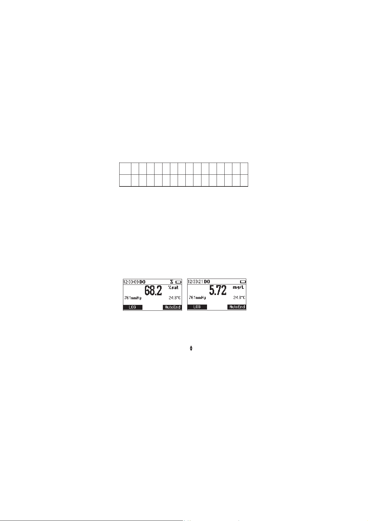
DO MEASUREMENTS
Make sure the probe’s protective cap has been removed.
In order to take accurate dissolved oxygen measurements make sure that the
instrument has been calibrated (see page 27 for details).
Press RANGE to access the DO measure screen. If necessary press MODE to
change the measuring unit.
Immerse the tip of the probe into the sample to be tested. Allow approximately one minute for the reading to stabilize (hourglass symbol turns off).
On the screen are displayed:
• Dissolved Oxygen reading in the selected unit (% saturation or mg/L)
• Temperature reading in the selected unit (°C or °F)
• Pressure reading in the selected unit (mmHg, inHg, atm, psi, kPa, mbar).
If the Manual Pressure option is enabled ( displayed in front of the pressure
value) the pressure value can be changed using the ARROW keys.
For accurate dissolved oxygen measurements, a water movement of
0.3 m/s is required. This is to ensure that the oxygen-depleted membrane
surface is constantly replenished. A moving stream will provide adequate
circulation.
14
Page 15
BOD MEASUREMENTS
Biochemical oxygen demand (BOD) is an indicator for the concentration of
biodegradable organic matter present in a sample of water. It can be used to
infer the general quality of the water and its degree of pollution. BOD
measures the rate of oxygen uptake by microorganisms in a sample of water
at a fixed temperature and over a given period of time. To ensure that all
other conditions are equal, a very small amount of microorganism seed is
added to each sample being tested. This seed is typically generated by
diluting activated sludge with deionized water. The samples are kept at 20 ºC
in the dark and tested for dissolved oxygen (DO) after five days. The loss of
dissolved oxygen in the sample, once correction have been made for the degree
of dilution, is called the BOD
5
Before measuring BOD, remember to set the BOD configuration from the
SETUP menu (see page 33).
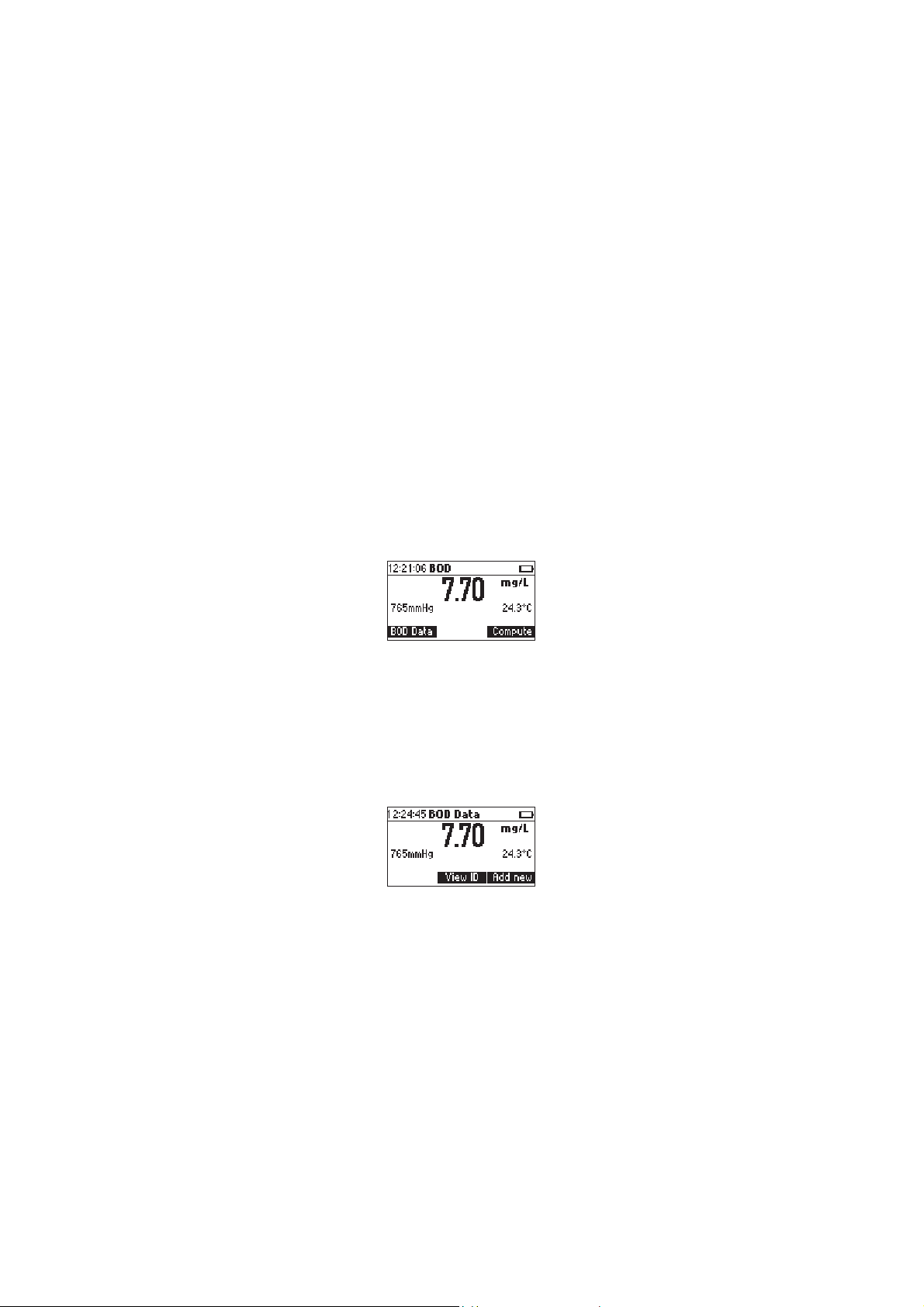
Press RANGE to access the BOD measure screen.
Press BOD Data to view the BOD initial data management screen.
Press Compute to evaluate the BOD for a specified sample (available only
when the measurement is stable and at least one initial BOD data record has
been memorized).
BOD initial data management screen
BOD Data is pressed while in BOD measurement screen.
Press Add new to add a new BOD initial data record (the key is available only
when the measurement is stable). A 200 records memory space is available
for BOD initial data.
Press View ID to view the saved BOD initial values (the key is available only
15
Page 16
when at least one initial BOD data record has been memorized).
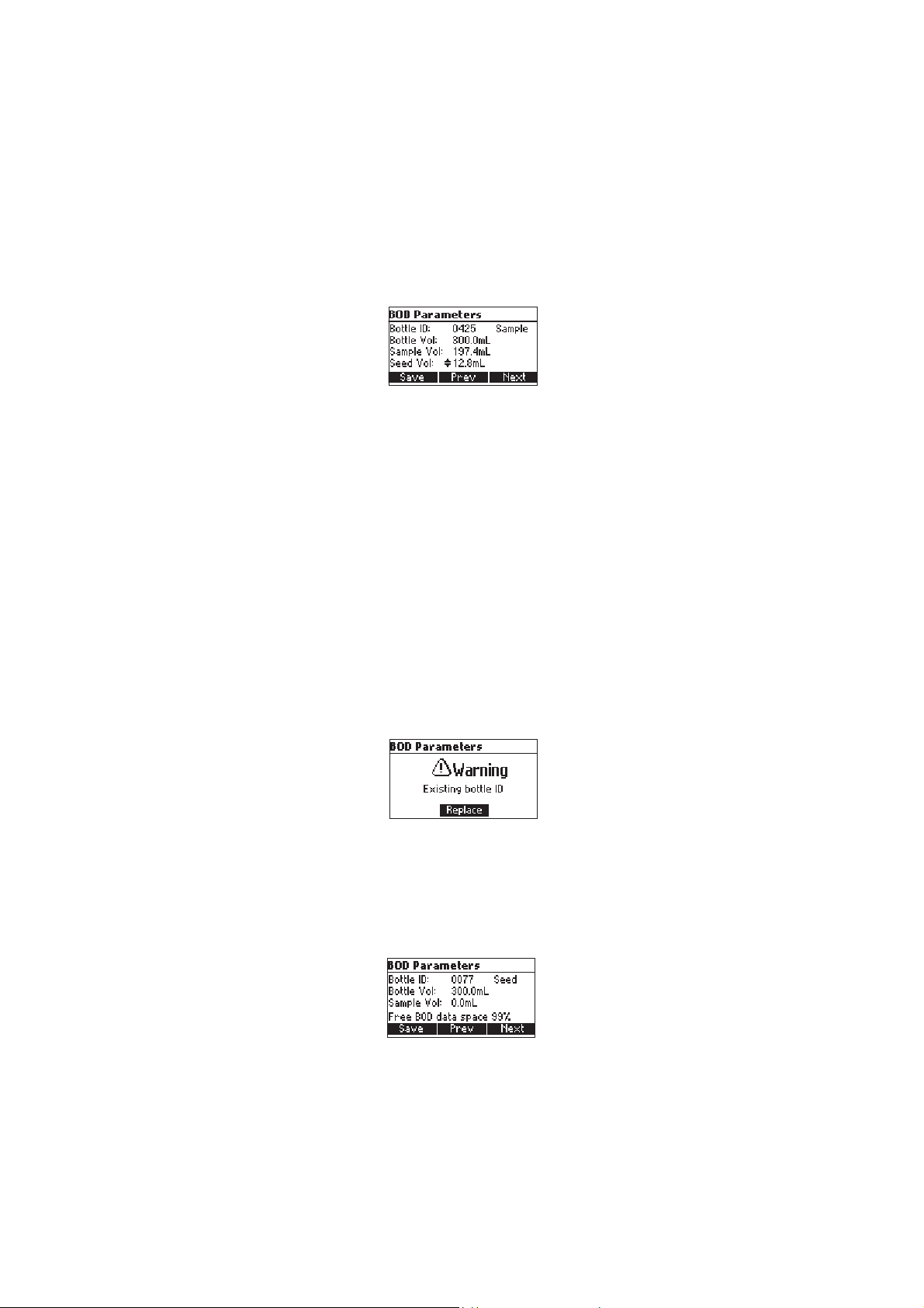
By pressing Add New the BOD Parameters screen will be displayed:
BOD Parameters:
• Bottle ID: a number used to identify a specific bottle.
Range: 0000 to 9999.
• The type of the Sample: Sample or Seed.
• Bottle Volume: the total volume of the BOD bottle.
Range: 0.1 to 300.0 mL.
• Sample Volume: the volume of sample in the BOD bottle.
Range: 0.1 to 300.0 mL (for a seed sample this value is 0.0 mL and
cannot be set).
• Seed Volume: the volume of seed in the BOD bottle.
Range: 0.0 to 300.0 mL.
Press Prev/Next to select a different parameter on the screen.
Press ARROW keys to modify the selected parameter’s value.
Press Save to save the BOD parameters and the initial DO, temperature,
pressure and salinity values for the specified bottle.
If a bottle with the same ID already exists, the instrument will ask for
replacement confirmation.
Press Replace to replace the existing record, or ESC to return to the previous
screen without replacing.
When a new record is saved the meter will display a message indicating the
remaining free BOD initial data space in %.
16
Page 17
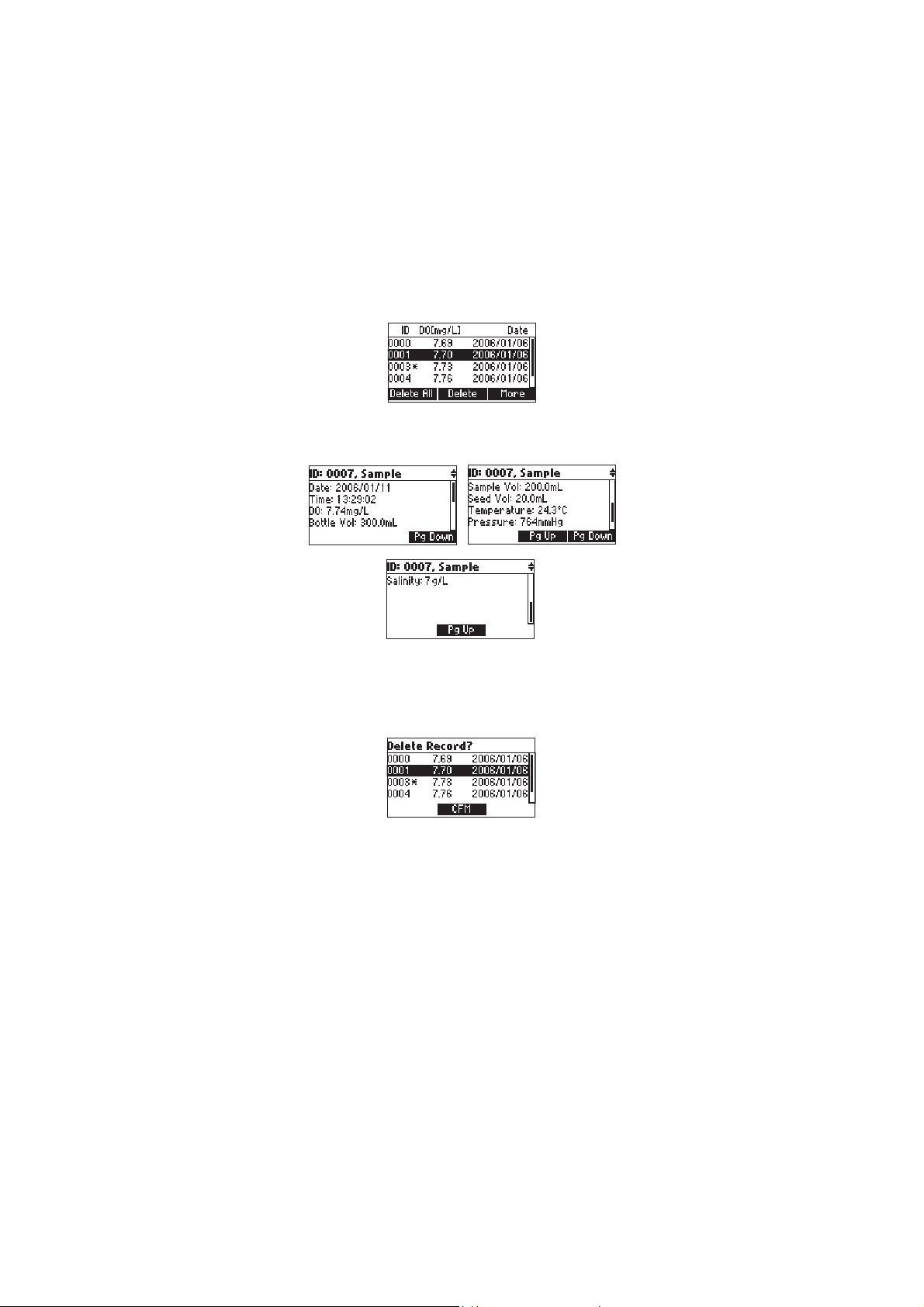
By pressing View ID a list of all the saved BOD initial data records will be
displayed. The seed records will have the symbol “*” displayed after the bottle
ID.
Use the ARROW keys to scroll the list of BOD initial data records.
Press More to view detailed information for the selected record.
Press PgUp/Pg/Down to view the next/previous screen of information.
Use the ARROW keys to view the detailed information about the
next/previous record.
If Delete is pressed.
Use ARROW keys to focus on the record to be deleted and then press CFM.
Press ESC to exit.
If Delete All is pressed the instrument asks for confirmation. Press CFM to
confirm or ESC to exit without deleting.
17
Page 18
BOD evaluation
From the BOD measure screen press Compute to evaluate the BOD for a
specified sample. The following screen will be displayed.
If the date of the current measurement is previous to the date of the selected
measurement then the Eval. BOD key will not be displayed.
Press MORE to view detailed information for the selected record.
Use ARROW keys to select the bottle for BOD evaluation.
Press Eval. BOD to compute the BOD for the selected bottle. If the time
difference between the current reading and the selected reading is less than
1 day the instrument will ask for record replacement confirmation, and the
BOD can’t be evaluated.
Press CFM to replace the selected record’s DO, temperature, pressure and
salinity values with the current values.
Press ESC to return to the previous screen without replacing.
If the conditions regarding the time difference are met, after pressing the
Eval.BOD key, the instrument will display the computed BOD value.
Press LOG to save the BOD result.
Press ESC to return to the BOD measure screen.
If the final DO reading or DO loss don’t meet the criteria for BOD measure-
ments set from the instrument’s setup, a warning message will be displayed.
18
Page 19
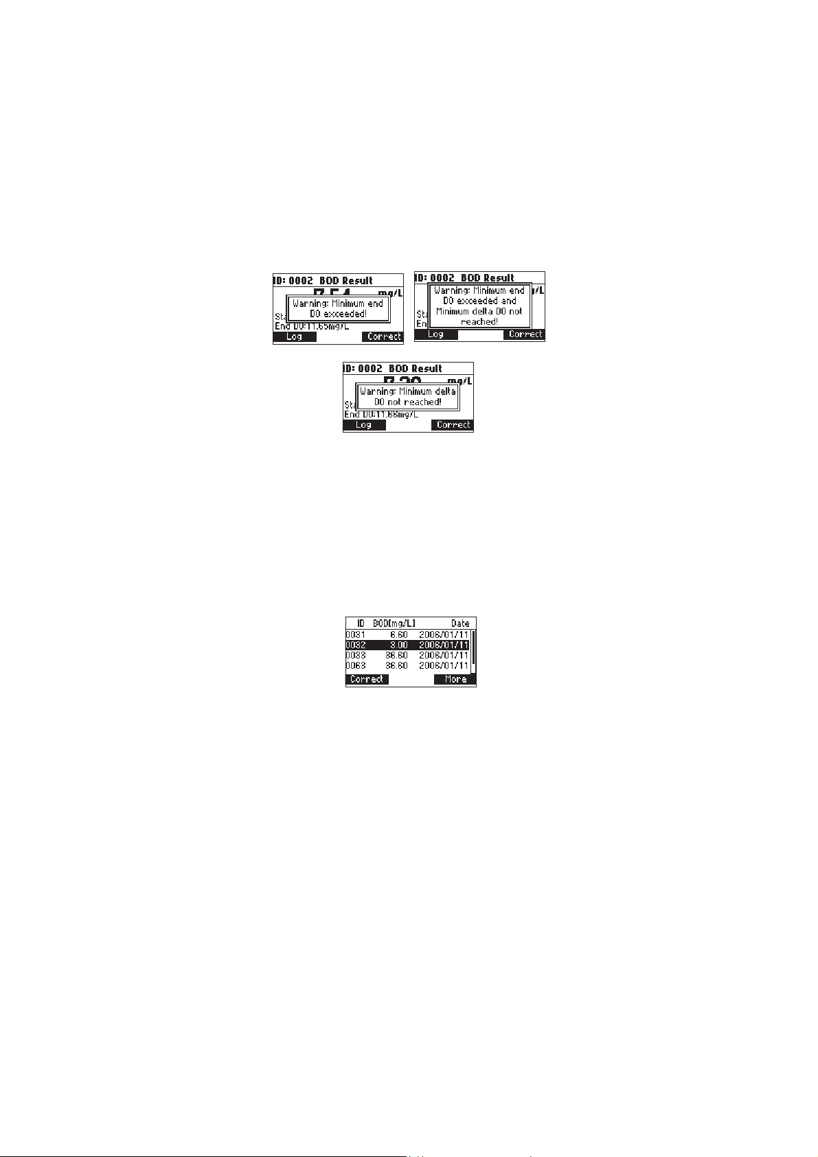
Press any key to clear the warning message from the display or press HELP to
view detailed information about the warning.
Note: If the Autodelete BOD start data option is enabled in SETUP
(see page 33), when the BOD result is saved (LOG key pressed) the
corresponding BOD initial data record will be automatically deleted
from the instrument’s memory.
Seed Correction
In case that the BOD was evaluated for a seeded sample and the list of the
saved seed BOD values is not empty, the Correct functional key will be
displayed.
Press Correct to view the list of the saved seed BOD values.
Select the desired seed BOD and then press Correct to compute the corrected
BOD value. The instrument will display the corrected BOD value.
If the information about the BOD of a certain seed doesn’t exist at the moment
of the BOD evaluation for a seeded sample, the sample’s BOD can be corrected
at a later time from the BOD recall menu (view logged BOD data).
In order to perform a seed correction from the BOD recall, press RCL key from
the BOD measurement screen to enter BOD recall, select the desired BOD
record and press More. The instrument will display a complete set of information about the selected record.
Press Correct to view the list of the seed values.
Select the desired seed BOD and then press Correct to compute the corrected
BOD value. The new BOD value will be displayed.
19
Page 20

Note: If the final DO value is greater than the initial DO value an error
message will be displayed.
20
Page 21
OUR MEASUREMENTOUR MEASUREMENT
OUR MEASUREMENT
OUR MEASUREMENTOUR MEASUREMENT
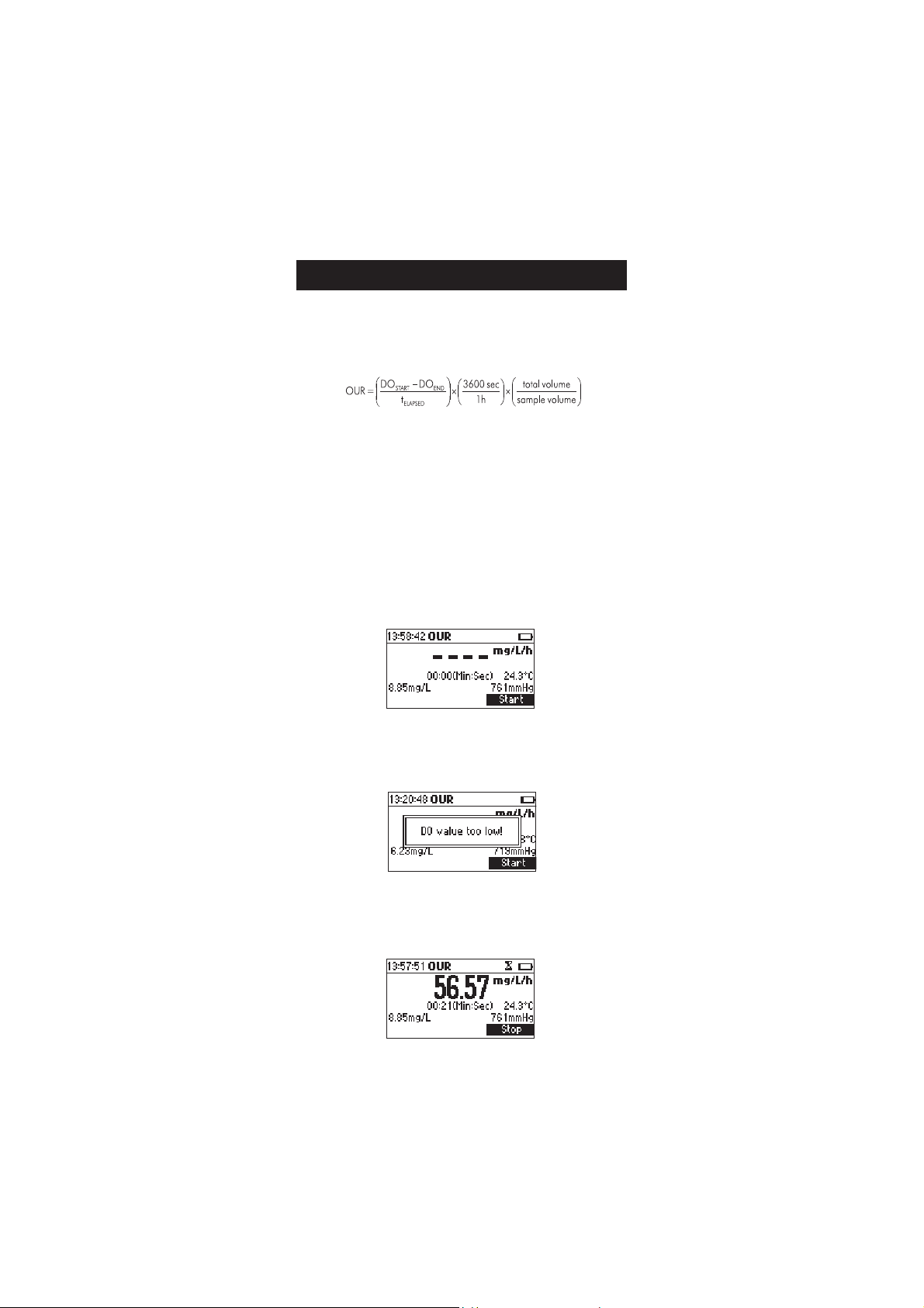
The OUR is used to determine the oxygen consumption or respiration rate. It
is defined as the mg/L of oxygen consumed per hour.
The following equation is used for OUR determination:
where:
DO
START = Dissolved oxygen level at start of test
DOEND = Dissolved oxygen level at end of test
tELAPSED = Elapsed time of test in seconds
total volume/sample volume = Dilution factor of sample
Before starting an OUR test remember to set the OUR configuration from the
SETUP menu (page 33).
OUR measure screen:
Press Start to begin a new OUR test.
If the DO value is less than the minimum start DO value the meter will
display an error message, and the test cannot be started.
If the minimum start DO condition is met the instrument will display the
instantaneous oxygen consumption rate and the amount of time that has
passed from the beginning of the test.
21
Page 22

If the DO reading is less than the minimum end DO value set during OUR
configuration a warning icon will be displayed and a beep will be heard
every two seconds. Press Stop to stop the test and the beeper.
To end the OUR test before the maximum time interval set during OUR
configuration press Stop.
If Stop is pressed before the minimum time for the OUR test has elapsed, the
instrument will display a warning message.
Press Resume to continue the test or Stop to end the test.
At the end of the test the meter will display the computed OUR value and the
duration of the test.
Press LOG to save a complete set of data regarding the OUR test.
Press Start to begin a new OUR test.
Notes:
• If at the end of the test the DO reading is less than the minimun end DO
value set during OUR configuration, a warning message will be displayed.
Press any key to clear the message from the screen, or press HELP to view
detailed information about the warning.
22
Page 23

• If the DO value at the end of the test is greater than the DO value from the
beginning of the test an error message will be displayed.
Press Start to begin a new OUR test or ESC to return to the OUR measure
screen.
23
Page 24

SOUR MEASUREMENTSOUR MEASUREMENT
SOUR MEASUREMENT
SOUR MEASUREMENTSOUR MEASUREMENT
The Specific Oxygen Uptake Rate (SOUR), also known as the oxygen consumption or respiration rate, is defined as the milligram of oxygen consumed
per gram of volatile suspended solids (VSS) per hour. This quick test has
many advantages: rapid measure of influent organic load and biodegradability, indication of the presence of toxic or inhibitory wastes, degree of
stability and condition of a sample, and calculation of oxygen demand rates
at various points in the aeration basin.
The following equation is used for SOUR determination:
SOUR = OUR / Solids Weight
where:
OUR is the Oxygen Uptake Rate (see equation on pag 20)
Solids Weight is the
g/L
Temperature correction:
The SOUR value is corrected to 20 °C (68 °F) according to the Farrel
and Bhide equation:
Where T is the measured temperature in °C and Q is a temperature
dependent variable:
This calculation is valid only for temperature values in the range 10 to 30 °C.
Temperature correction is performed only if the option SOUR @20°C is
enabled from SOUR configuration in the setup menu.
Before starting a SOUR test remember to set the SOUR configuration from
the setup menu.
SOUR measure screen:
Total solids
Q= 1.05 for T above 20 °C
Q= 1.07 for T below 20 °C
or the
Volatile suspended solids
SOUR20=SOURTxQ
(20-T)
weight in
If the SOUR value is corrected to 20 °C (68 °F) the message “@20°C”, or
”@68°F” according to the currently selected temperature unit, will be
displayed above the measured temperature.
Press Start to begin a new SOUR test.
24
Page 25

If the DO value is less than the minimum start DO value, the meter will
display an error message, and the test cannot be started.
If the minimum start DO condition is met the instrument will display the
instantaneous specific oxygen consumption rate and the amount of time that
has passed from the beginning of the test.
In case that the SOUR value is corrected to 20 °C (68 °F) and the measured
temperature isn’t in the range 10 to 30 °C the temperature value will blink
to alert that the temperature correction isn’t valid.
If the DO reading is less than the minimun end DO value set during SOUR
configuration, a warning icon will be displayed and a beep will be heard
every two seconds. Press Stop to stop the test and the beeper.
To end the SOUR test before the maximum interval set during SOUR
configuration press Stop.
If Stop is pressed before the minimum time for the SOUR test has elapsed the
instrument will display a warning message.
Press Resume to continue the test or Stop to end the test.
25
Page 26

At the end of the test the meter will display the computed SOUR value and
the duration of the test.
Press LOG to save a complete set of data regarding the SOUR test.
Press Start to begin a new SOUR test.
Notes:
• If the DO reading is less than the minimun end DO value set during SOUR
configuration, a warning message will be displayed.
Press any key to clear the message from the screen, or press HELP to view
detailed information about the warning.
• If the DO value is greater than the DO value from the beginning of the test
an error message will be displayed.
Press Start to begin a new SOUR test or ESC to return to the SOUR
measure screen.
26
Page 27

TEMPERATURE MEASUREMENTSTEMPERATURE MEASUREMENTS
TEMPERATURE MEASUREMENTS
TEMPERATURE MEASUREMENTSTEMPERATURE MEASUREMENTS
The DO probe has a built-in temperature sensor.
The measured temperature is indicated on the display.
Allow the probe to reach thermal equilibrium before taking any measurements. This can take several minutes. The greater the difference between the
temperature at which the probe was stored and the temperature of the
sample, the longer the time will be.
Note: If “----” is displayed instead of the measured temperature, the D.O.
probe is not properly connected or the temperature is out of range.
This also indicates the possibility of a broken probe cable.
DO CALIBRATION PROCEDUREDO CALIBRATION PROCEDURE
DO CALIBRATION PROCEDURE
DO CALIBRATION PROCEDUREDO CALIBRATION PROCEDURE
The following options are available for the Dissolved Oxygen calibration:
• one point automatic zero calibration at 0% saturation or 0 mg/L
• one point automatic slope calibration at 100% saturation or 8.26 mg/L
• 2 points automatic calibration at 0% saturation (0 mg/L) and 100%
saturation(8.26 mg/L)
• 1 point manual calibration using a standard value set by the user in %
saturation or mg/L
When automatic calibrations are performed it is assumed that the standard
value is the saturated DO value at 25 °C, 0 g/L salinity and 760 mmHg.
When manual calibrations are performed it is assumed that the standard
value is the DO value at the current pressure, temperature and salinity.
INITIAL PREPARATION
Make sure the probe is ready for measurements (see probe connection and
preparation on page 10), i.e. the membrane is filled with electrolyte and the
probe is connected to the meter.
For an accurate calibration, it is recommended to wait for at least 15 minutes
to ensure precise conditioning of the probe.
Remove the protective cap from the D.O. probe.
Make sure the salinity value has been set to the salinity of the standard (see
SETUP for details)
One point automatic zero calibration
Submerge the probe into HI 7040 zero oxygen solution and stir gently for
2-3 minutes.
27
Page 28

Press CAL. The calibration menu will be displayed.
Press DO to select the DO calibration.
The DO calibration screen will be displayed and the standard 0% saturation
(or 0 mg/L, depending on the currently selected measuring unit), will be
automatically selected.
The hourglass icon will be shown on the display until the reading becomes
stable.
When the reading is stable and close to the selected standard, the CFM
functional key is displayed.
Press CFM to confirm the calibration point.
Press ESC
to leave calibration. The instrument will return to the main screen
and will memorize the zero calibration data.
One point automatic slope calibration
It is suggested to perform the slope calibration in air. Allow the probe tip to
dry.
Press CAL. The calibration menu will be displayed. Press DO to select the DO
calibration. The 100% saturation standard (or the 8.26 mg/L standard,
according to the currently selected measuring unit), will be automatically
selected.
28
Page 29

The hourglass icon will be shown on the display until the reading becomes
stable.
When the reading is stable and close to the selected buffer, the CFM
functional key is displayed.
Press CFM to confirm the calibration point.
The instrument will return to the main screen and will memorize the slope
calibration data.
Two points automatic calibration
Submerge the probe into HI 7040 zero oxygen solution and stir gently for
2-3 minutes.
Press CAL. The calibration menu will be displayed.
Press DO to select the DO calibration. The DO calibration screen will be
displayed and the standard 0% saturation (0 mg/L) will be automatically
selected.
The hourglass icon will be shown on the display until the reading becomes
stable.
When the reading is stable and close to the selected standard, the CFM
functional key is displayed.
Press CFM to confirm the calibration point.
The meter will automatically select the 100% saturation (8.26 mg/L) standard.
Leave the probe in air.
The hourglass icon will be shown on the display until the reading becomes
stable.
When the reading is stable and close to the selected standard, the CFM
functional key is displayed.
Press CFM to confirm the calibration point. The instrument will return to the
main screen and will memorize the calibration data.
One point manual calibration
First determine the dissolved oxygen value of the sample (use a Winkler
titration). Place the probe in the sample and provide adequate stirring.
Access the DO calibration screen as described in the previous DO calibration
procedures.
29
Page 30

Press the Manual functional key.
The standard value can be changed using the ARROW keys in the range 0
to 100% saturation or 0 to 8.26 mg/L, depending on the currently selected
measuring unit.
Set the standard value to the determined DO value.
The hourglass icon will be shown on the display until the reading becomes
stable.
When the reading is stable and close to the selected buffer, the CFM
functional key is displayed.
Press CFM to confirm the calibration point.
The instrument will return to the main screen and will memorize the calibration data.
::
Notes
:
::
• If the manual pressure feature is enabled, during the DO calibration it is
possible to switch between changing the standard value or the pressure
value by pressing the Pressure/Standard functional key or the MODE
key.
• If a previous calibration has been performed it is possible to erase the
calibration by pressing the Clear functional key while in the DO calibration screen.
30
Page 31

The “Calibration cleared” message will be displayed for a few seconds
and the meter will return to the main screen. If the manual pressure
feature is enabled, the
accessing the DO calibration screen, and afterwards it will be replaced by
the Pressure/Standard functional key.
• If the DO value measured by the instrument is not close to the selected
standard, the “Wrong standard” error message will be shown on the
display and the calibration can’t be confirmed.
• While in manual calibration mode it is possible to return to the automatic
calibration mode by pressing the AUTO functional key. The meter will
select the standard that is closest to the current DO reading.
ClearClear
Clear key will be active only for 5 seconds after
ClearClear
31
Page 32

GOOD LABORATORY PRACTICE (GLP)GOOD LABORATORY PRACTICE (GLP)
GOOD LABORATORY PRACTICE (GLP)
GOOD LABORATORY PRACTICE (GLP)GOOD LABORATORY PRACTICE (GLP)
GLP is a set of functions that allows storage and retrieval of data regarding the
maintenance and status of the electrode.
All data regarding DO calibration is stored for the user to review when
necessary.
EXPIRED CALIBRATION
The instrument is provided with a real time clock (RTC), in order to monitor the
time elapsed since the last DO calibration.
The real time clock is reset every time the instrument is calibrated and the
“expired calibration” status is triggered when the instrument detects a
calibration time out. The “CAL” “DUE” tags will start blinking to warn the
user that the instrument should be recalibrated.
The calibration time out can be set (see SETUP for details, page 33) from 1 to
7 days or can be disabled.
For example, if a 4 days time out has been selected, the instrument will issue
the alarm exactly 4 days after the last calibration.
However, if at any moment the expiration value is changed (e.g. to 5 days),
then the alarm will be immediately recalculated and appear 5 days after the
last calibration.
Notes: • When the instrument is not calibrated or the calibration is cleared
(default values loaded) there is no “expired calibration”, and the
display always shows the “CAL” “DUE” tags blinking.
• When an abnormal condition in the RTC is detected, the instrument
forces the “expired calibration” status.
LAST DO CALIBRATION DATA
The last DO calibration data is stored automatically after a successful calibration. To view the last calibration data, press GLP when the instrument is in the
DO, BOD, OUR or SOUR measurement mode.
The instrument will display a lot of data including calibration standard,
salinity, pressure and temperature.
Note: “Not user calibration” message is displayed if the calibration was
cleared or the instrument hasn’t been calibrated for dissolved oxygen.
32
Page 33

SETUPSETUP
SETUP
SETUPSETUP
Setup mode allows viewing and modifying the measurement parameters.
The following table lists the SETUP parameters, their valid range and the
factory default settings.
Item Description Valid Value Default
Calibr. Time-out Number of days after Disabled, 1 to 7 days Disabled
calibr. warning is displayed
Salinity The solution’s salt content 0 to 70 g/L 0 g/L
BOD
Configuration
-Sample min The minimum diff. between 0.00 to 50.00 mg/L 0.00 mg/L
delta DO the start and the end DO val.
-Sample min The minimum end DO value 0.00 to 50.00 mg/L 0.00 mg/L
end DO
-Seed min The minimum diff. between 0.00 to 50.00 mg/L 0.00 mg/L
delta DO the start and the end DO val.
-Seed min The minimum end DO value 0.00 to 50.00 mg/L 0.00 mg/L
end DO
OUR
Configuration
-Min time The minimum time for the 1 to 3600 sec. 1 s
OUR test
-Max time The maximum time for the 1 to 3600 sec. 3600 sec.
OUR test
-Min start DO The minimum DO value 0.01 to 50.00 mg/L 0.01 mg/L
for starting the OUR test
-Min end DO The minimum DO value at 0.00 to 50.00 mg/L 0.00 mg/L
the end of the OUR test
-Total volume The total volume of the 0.1 to 300.0 mL 0.1 mL
solution to be tested
-Sample volume The volume of sample in 0.1 to 300.0 mL 0.1 mL
the solution to be tested
SOUR
configuration
-Min time The minimum 1 to 3600 sec. 1 sec.
time for the SOUR test
-Max time The maximum
time for the SOUR test 1 to 3600 sec. 3600 sec.
-Min start DO The minimum DO value
for starting the SOUR test 0.01 to 50.00 mg/L 0.01 mg/L
-Min end DO The minimum DO value at 0.00 to 50.00 mg/L 0.00 mg/L
the end of the test
33
Page 34

-Total volume The total volume
of the solution to be tested 0.1 to 300.0 mL 0.1 mL
-Sample volume The volume of sample
in the solution to be tested 0.1 to 300.0 mL 0.1 mL
-Solids weight Total solids or Volatile 0.1 to 300.0 g/L 0.1 g/L
Suspended solids weight
-SOUR@20 ºC Correct the SOUR value Enabled or Disabled Disabled
to 20 ºC
Autodelete Automatically delete BOD Enabled or Disabled Disabled
BOD start data start data, after BOD
compute
Manual pressure Set the pressure value Enabled or disabled Disabled
using the ARROW keys
Pressure unit mmHg mmHg
inHg
atm
mbar
ps i
kP a
Temperature unit ºC or ºF º C
Backlight Backlight Level 0 to 8 4
Contrast Contrast Level 0 to 20 10
Auto Light Off Time until backlight is ON 1, 5, 10, 30 5
AutoPower off Time after the Disabled 5
instrument is powered OFF 5, 10, 30, 60
Date/ Time 01.01.2006 to 12.31.2099 01.01.2006
00 :00 to 23 :59
Time Format AM/PM or 24 hours 24 hours
Date format DD/MM/YYYY YYYY/MM/DD
MM/DD/YYYY
YYYY/MM/DD
YYYY-MM-DD
MonDD,YYYY
DD-Mon-YYYY
YYYY-Mon-DD
Language Message display language Up to English
4 languages
Beep ON Beeper Status Enabled or Disabled Disabled
Instrument ID Instrument identification 0000 to 9999 0000
Baud Rate Serial Communication 600, 1200, 1800, 9600 4800
Meter Displays general
Information informations
34
Page 35

PARAMETER SCREENSPARAMETER SCREENS
PARAMETER SCREENS
PARAMETER SCREENSPARAMETER SCREENS
Calibration timeout
Focus on the
Press Modify.
Use the ARROW keys to set the desired value.
Press Accept to confirm or ESC to return without saving.
Note: If enabled “CAL DUE” warning will be displayed, the set number of
days after calibration is over passed.
Salinity
Focus on
Calibration Timeout
Salinity
item.
item.
Press Modify.
Use ARROW keys to change the salinity value. Press Accept to confirm or ESC
to exit without saving.
35
Page 36

BOD configuration
Focus on
BOD
configuration item.
Press Select.
Parameters:
• Sample min D DO -the minimum acceptable difference between the
initial and final DO values for a sample. If the difference is less than this
value the meter will show a warning message when evaluating the BOD.
Range: 0.00 to 50.00 mg/L.
• Sample min end DO - the minimum acceptable final DO value for a
sample. If the final DO value is less than this value the meter will show a
warning message when evaluating the BOD.
Range: 0.00 to 50.00 mg/L.
• Seed min D DO - the minimum acceptable difference between the initial
and final DO values for a seed sample. If the difference is less than this
value the meter will show a warning message when evaluating the BOD.
Range: 0.00 to 50.00 mg/L.
• Seed min end DO - the minimum acceptable final DO value is less than
this value the meter will show a warning message when evaluating the
BOD.
Range: 0.00 to 50.00 mg/L.
Press Prev/Next to select a different parameter.
Press ARROW keys to modify the selected parameter’s value.
Press Save to save the new BOD configuration.
Press ESC to leave without changing.
36
Page 37

OUR configuration
Focus on
OUR
configuration item.
Press Select.
Parameters:
• Min time - the minimum time for the OUR test.
Range: 1 to 3600 seconds.
• Max time - the maximum time for the OUR test. The test will stop
automatically when the maximum time has elapsed.
• Min start DO - the minimum accepted DO value for starting the OUR test.
If the DO reading is less than this value the test cannot be started.
Range: 0.00 to 50.00 mg/L.
• Min end DO - the minimum accepted DO value at the end of the test. If
the DO reading at the end of the OUR test is less than this value a
warning message will be displayed.
Range: 0.01 to 50.00 mg/L..
• Total volume - the volume of the diluted mixture.
Range: 0.1 to 300.0 mL
• Sample volume - the volume of sample in the diluted mixture.
Range: 0.1 to 300.0 mL.
Press Prev/Next to select a different parameter.
Press ARROW keys to modify the selected parameter’s value.
Press Save to save the new OUR configuration.
Press ESC to leave without changing.
SOUR configuration
Focus on
SOUR configuration
item.
37
Page 38

Press Select.
• Min time - the minimum time for the SOUR test.
Range: 1 to 3600 seconds.
• Max time - the maximum time for the SOUR test. The test will stop
automatically when the maximum time has elapsed.
Range: 0.00 to 50.00 mg/L.
• Min start DO - the minimum accepted DO value for starting the SOUR
test. If the DO reading is less than this value the test cannot be started.
Range: 0.01 to 50.00 mg/L.
• Min end DO - the minimum accepted DO value at the end of the test. If
the DO reading at the end of the SOUR test is less than this value a
warning message will be displayed.
Range: 0.00 to 50.00 mg/L.
• Total volume - the volume of the diluted mixture.
Range: 0.1 to 300.0 mL
• Sample volume - the volume of sample in the diluted mixture.
Range: 0.1 to 300.0 mL.
• Solids weight: Total solids or Volatile suspended solids weight.
Range: 0.1 to 300.0 g/L.
• SOUR@20 °C: If this option to enabled the SOUR value is corrected to
20°C.
Press Prev/Next to select a different parameter.
Press ARROW keys to modify the selected parameter’s value.
Press Save to save the new SOUR configuration.
Press ESC to leave without changing.
Autodelete BOD start data
Focus on the
Autodelete BOD
start data item.
Press the displayed functional key to enable/disable the feature.
If enabled the BOD initial data record used in BOD result evaluation is deleted
automatically after the BOD result has been saved into the instrument’s
memory (LOG key pressed).
38
Page 39

If disabled, the user has to delete BOD initial data records that were used in
BOD result evaluation, entering View initial BOD data mode.
Manual pressure
Focus on
Manual pressure
Press the displayed functional key to enable/disable the feature.
If enabled, the pressure can be entered by the user, while in measurement
screen, using ARROW keys.
Pressure unit
Focus on
Pressure unit
Press Modify.
item.
item.
Use ARROW keys to focus on the desired pressure unit.
Press Accept to confirm or ESC to exit without saving.
39
Page 40

Temperature unit
Focus on the
Press the displayed functional key in order to change the temperature unit.
Backlight
Focus on
Press Modify.
Use / keys to change intensity then press Accept to confirm.
Press ESC to leave without changing.
Temperature unit
Backlight
item.
option.
Contrast
Focus on the
Press Modify.
Contrast
item.
40
Page 41

Use / keys to change intensity then press Accept to confirm.
Press ESC to leave without changing.
AutoLightOff
Focus on the
Press one of the functional key to change the option.
AutoPowerOff
Focus on the
Press Modify.
AutoLightOff
AutoPowerOff
item.
item.
Use ARROW keys to select interval then press Accept.
Press ESC to leave without changing.
Date/Time
Focus on the
Date/Time
item.
41
Page 42

Press Modify.
Use / keys to select item. Use ARROW keys to change the focused
values.
Press Accept to confirm the new setting, or ESC to leave without changing.
Time Format
Focus on the
Press functional key to change the option.
Date Format
Focus on the
Time Format
Date Format
item.
item.
Press Modify.
Use ARROW keys to select date format then press Accept.
Press ESC to leave without changing.
42
Page 43

Language
Focus on the
Use the desired functional key to change the option. Wait until the new
language is loaded.
If any language can be loaded, the instrument will work in safe mode. In this
mode all messages are displayed in English and Help is not available.
BeepOn
Focus on the
Press the displayed functional key to enable/disable key.
When enabled, beep sounds as a short beep every time a key is pressed or
when the calibration can be confirmed.
A long beep alert that the pressed key is not active or a wrong condition is
detected while in calibration.
Instrument ID
Focus on the
Language
BeepOn
Instr.ID
item.
item.
item.
Press Modify.
Use ARROW keys to change the instrument’s ID. Press Accept to confirm or
ESC to exit without saving.
43
Page 44

BaudRate
Focus on the
Press Modify.
Use ARROW keys to select the desired communication baud. Press Accept to
confirm or ESC to exit.
Meter Information
Focus on the
BaudRate
item.
Meter information
item.
Press Select.
The meter informations are displayed:
-firmware version
-language version
-DO and temperature factory calibration date/time
-battery capacity
44
Page 45

LOGGINGLOGGING
LOGGING
LOGGINGLOGGING
This feature allows the user to log DO, BOD, OUR and SOUR measurements.
All logged data can be transferred to a PC through the USB or RS232 port.
The maximum logging space is 400 records.
LOGGING THE CURRENT DATA
To store the current reading into memory, press LOG.
The instrument will displays for a few seconds the record number and the
amount of the free log space (in %).
If the LOG space is full, the “Log space is full” message will be displayed for
a few seconds when Log key is invoked.
Enter View Logged Data mode and delete records in order to free log space.
VIEW LOGGED DATA
Press RCL to retrieve the stored information while in measurement mode for
the specific range (DO, BOD, OUR, SOUR).
The list of records is displayed.
DO recall:
45
Page 46

BOD recall:
OUR recall:
SOUR recall:
If no data were logged, the instrument will display “No Records”.
Use ARROW keys to scroll the list of records.
Press Delete All to enter
Press Delete to enter
Press More to view more information of the focused record.
If More is pressed, a complete set of information are displayed.
Press PgUp or PgDown to toggle between information screens.
DO recall:
Delete All
Delete
screen.
records screen.
BOD recall:
46
Page 47

Note: • “S.C. “ message in the title bar means seed corrected.
• “not S.C.” message in the title bar means seed not corrected.
The Correct functional key will be displayed if the BOD result was not seed
corrected.
Note: For a seed corrected sample, on last page will be shown the
Seed bottle ID used for correction.
OUR recall:
SOUR recall:
47
Page 48

Note: In case that the SOUR value was corrected to 20 °C the message
“(@20°C)” will be displayed before the SOUR value.
Use ARROW keys to view the complete log information about the next/
previous record while are displayed.
If Delete is pressed.
Use ARROW key to focus the record to be deleted and then press CFM.
Press ESC to exit.
If Delete All is pressed the instrument asks for confirmation. Press CFM to
confirm or ESC to exit without deleting.
AA
utoEndutoEnd
A
utoEnd
AA
utoEndutoEnd
To freeze the first stable reading on the LCD press AutoEnd while the instru-
ment is in DO measurement mode.
The “Wait” symbol will blink until the reading is stable.
When the reading is stable “Hold” icon will be displayed.
Press Continue at any moment in order to enter continuous reading mode.
48
Page 49

PRESSURE CALIBRATIONPRESSURE CALIBRATION
PRESSURE CALIBRATION
PRESSURE CALIBRATIONPRESSURE CALIBRATION
The HI 98186 meter has an internal barometer for automatic pressure
compensation for DO readings. The instrument is factory calibrated for pressure measurements and no user calibration is needed. If the pressure reading is inaccurate, pressure calibration should be performed.
For an accurate calibration, contact your dealer or the nearest Hanna
Customer Service Center or follow the instruction below.
In order to perform pressure calibration a reference barometer with at least
1 mmHg resolution is necessary.
Press CAL from any measure mode (DO, BOD, OUR or SOUR). The calibration
menu will be displayed.
Press Pressure functional key to select the pressure calibration. The pressure
calibration screen will be displayed.
Using the ARROW keys, enter the true local barometric pressure read from
the reference barometer. Do NOT use the pressure reported by the weather
bureau. Weather bureaus correct pressures to sea level.
When the reading is stable and close to the entered barometric pressure the
CFM functional key is displayed.
Press CFM to confirm the calibration.
The instrument will return to the main screen and will memorize the calibration data.
49
Page 50

Note: • If a pressure calibration has been previously performed it is possible
to erase the calibration by pressing the Clear functional key.
• The “Calibration cleared” message will be displayed for a few
seconds and the meter will return to the main screen.
• If the measured pressure is too far from the calibration point the
“Wrong pressure” error message will be shown on the display and
the calibration can’t be confirmed.
Verify if the value read from the reference barometer was entered correctly.
Contact the Hanna Service if calibration cannot be performed.
50
Page 51

TEMPERATURE CALIBRATIONTEMPERATURE CALIBRATION
TEMPERATURE CALIBRATION
TEMPERATURE CALIBRATIONTEMPERATURE CALIBRATION
((
for technical personnel onlyfor technical personnel only
(
for technical personnel only
((
for technical personnel onlyfor technical personnel only
All the instruments are factory calibrated for temperature.
Hanna’s DO probes are interchangeable and no temperature calibration is
needed when they are replaced.
If the temperature measurements are inaccurate, temperature recalibration
should be performed.
For an accurate recalibration, contact your dealer or the nearest Hanna
Customer Service Center, or follow instructions below.
The temperature calibration can be performed in 1 or 2 points.
It is better to perform a 2 points calibration.
The calibration can be performed in any two points that have at least 25 ºC
distance between. It is recommended that the first point be near 0 ºC and the
second point near 50 ºC.
Press CAL from any measure mode (DO, BOD, OUR or SOUR).
The calibration menu will be displayed.
Press the T functional key to select the temperature calibration.
• Prepare a vessel containing ice and water and another one containing hot
water (at approximately 50 °C or 122 °F). Place insulation material
around the vessels to minimize temperature changes.
Use a calibrated thermometer with a resolution of 0.1 °C as a reference
thermometer.
• Connect the DO probe to the appropriate socket.
• Immerse the DO probe into the vessel with ice and water as close as possible
to the reference thermometer.
• Allow a few seconds for the probe to stabilize.
))
)
))
51
Page 52

• Use the ARROW keys to set the calibration point values to that of the ice
and water mixture, measured by the reference thermometer.
• When the reading is stable and close to the selected calibration point, the
CFM functional key is displayed.
• Press CFM to confirm.
• The second expected calibration point is displayed.
• Immerse the DO probe into the second vessel as close as possible to the
reference thermometer.
• Allow a few seconds for the probe to stabilize.
• Use the ARROW key to set the calibration point value to that measured
by the reference thermometer.
52
Page 53

• When the reading is stable and close to the selected calibration point, the
CFM functional key is displayed.
• Press CFM to confirm. The instrument returns to the main screen.
Note: •If the reading is not close to the selected calibration point or the
difference between first selected point and second selected point is
less than 25 ºC, “Wrong” message will blink.
• If the WRONG source is the difference between calibration points
increase the temperature of the vessel with hot water in order to be
acceptable.
• If the WRONG source is the temperature reading change the probe
and restart calibration.
If calibration cannot be performed contact Hanna Service.
• If a temperature calibration has been previously performed it is
possible to erase the calibration by pressing the Clear functional
key.
• The “Calibration cleared” message will be displayed for a few
seconds and the meter will return to the main screen.
•For one point calibration press ESC after first point was confirmed.
The instrument will return to the main screen and will memorize
the calibration data.
53
Page 54

PC INTERFACEPC INTERFACE
PC INTERFACE
PC INTERFACEPC INTERFACE
Data transmission from the instrument to the PC can be done with the HI 92000
Windows® compatible software (optional). HI 92000 also offers graphing and
on-line help feature.
Data can be exported to the most popular spreadsheet programs for further analysis.
To connect your instrument to a PC, use an USB cable connector. Make sure
that your instrument is switched off and plug one connector to the instrument
USB socket and the other to the serial or USB port of your PC.
Note: • If you are not using Hanna Instruments HI 92000 software,
please see the following instructions.
SENDING COMMANDS FROM PC
It is also possible to remotely control the instrument with any terminal program.
Use an USB cable to connect the instrument to a PC, start the terminal program
and set the communication options as follows: 8, N, 1, no flow control.
COMMAND TYPES
To send a command to the instrument follow the next scheme:
<command prefix> <command> <CR>
where: <command prefix> is a selectable 16 ASCII character.
<command> is the command code.
Note: Either small or capital letters can be used.
SIMPLE COMMANDS
KF1 Is equivalent to pressing functional key 1
KF2 Is equivalent to pressing functional key 2
KF3 Is equivalent to pressing functional key 3
RNG Is equivalent to pressing RANGE
MOD Is equivalent to pressing MODE
CAL Is equivalent to pressing CAL
UPC Is equivalent to pressing the UP arrow key
DWC Is equivalent to pressing the DOWN arrow key
RCL Is equivalent to pressing RCL
SET Is equivalent to pressing SETUP
GLP Is equivalent to pressing GLP
OFF Is equivalent to pressing OFF
54
Page 55

CHR xx Change the instrument range according with the parameter
value (xx):
• xx=20 DO range
• xx=21 BOD range
• xx=22 OUR range
• xx=23 SOUR range
The instrument will answer for these commands with:
<STX> <answer> <ETX>
where: <STX> is 02 ASCII code character (start of text)
<ETX> is 03 ASCII code character (end of text)
<answer>:
<ACK> is 06 ASCII code character (recognized command)
<NAK> is 21 ASCII code character (unrecognized command)
<CAN> is 24 ASCII code character (corrupted command)
COMMANDS REQUIRING AN ANSWER
The instrument will answer for these commands with:
<STX> <answer> <checksum> <ETX>
where the checksum is the bytes sum of the answer string sent as 2 ASCII characters.
All the answer messages are with ASCII characters.
RAS Causes the instrument to send a complete set of readings in according
with the current range:
• DO, temperature, and pressure on the DO and BOD range
• DO, temperature, pressure, OUR/SOUR value, OUR/SOUR test time
on the OUR/SOUR range
• BOD result, start DO value and end DO value when in the BO result
screen (meter mode 25)
The answer string contains:
• Meter mode (2 chars):
- 20 - DO range
- 21 - BOD range
- 22 - OUR range
- 23 - SOUR range
- 25 - BOD result screen
• Meter status (2 chars of status byte): represents a 8 bit hexadeci-
mal encoding
55
Page 56

• 0x10: temperature probe connection
• 0x20: DO measure unit (0 = %, 1= mg/L)
• 0x01:
GLPGLP
new
GLP data available
GLPGLP
• 0x02: new setup parameter
• 0x04: out of calibration range
• 0x08: the meter is in autoend mode;
• Reading status: R - in range, O - over range, U - under range
• The following status flags are sent for all modes except
mode 25
• DO reading range flag
• temperature reading range flag
• pressure reading range flag
• OUR/SOUR reading range flag (sent only if in OUR/SOUR
measure mode)
• The following status flag is sent only for mode 25
• BOD reading range flag
• Readings
• The following values are sent for all modes except
mode 25
• DO reading, including sign and decimal point (8 chars)
• temperature, including sign and decimal point (8chars)
• pressure value, including sign and decimal point, always
in mmHg (11 chars)
• OUR/SOUR reading, including sign and decimal point
(sent only if in OUR/SOUR measure mode) (8 chars)
• OUR/SOUR counter (sent only if in OUR/SOUR measure
mode) (4 chars)
• The following values are sent only for mode 25
• BOD reading, including sign and decimal point (8 chars)
• initial DO value, including sign and decimal point [mg/L]
(6 chars)
• final DO value, including sign and decimal point [mg/L]
(6 chars)
MDR Requests the instrument model name and firmware code (16 ASCII chars).
GLP Requests the calibration data record.
The answer string contains:
• the number of calibrated buffers (1 char)
• calibrated buffer unit (0 = %, 1 = mg/L) (1 char)
• buffer value including sign and decimal point (6 chars)
• calibrated buffer unit (0 = %, 1 = mg/L) (this value is sent only
if there is a 2 point calibration) (1 char)
56
Page 57

• buffer value including sign and decimal point (this value is sent only
if there is a 2 point calibration) (6 chars)
• salinity value (3 chars)
• pressure value in mmHg, including sign and decimal point
(11 chars)
• temperature value including sign and decimal point (8 chars)
• calibration time: yymmddhhmmss (12 chars).
PAR Requests the setup parameters setting.
The answer string contains:
• backlight value (1 char)
• contrast value (2 chars)
• instrument ID (4 chars)
• calibration alarm timeout (2 chars)
• Setup information (2 chars): 8 bit hexadecimal encoding:
- -
• 0x01:
- beep is on
- -
- -
• 0x04:
- Celsius / Fahrenheit display (°C if the bit is set)
- -
• 0x10: - manual pressure (1 if activated, 0 otherwise)
• Auto Light-off time (3 chars)
• Auto Power-off time (3 chars)
• Salinity value (3 chars)
• Pressure unit (1 char): 0 - mmHg, 1 - inHg, 2 - atm, 3 - mbar,
4 - psi, 5 - kPa
• BOD configuration values
• sample minimum delta DO, including sign and decimal point
(6 chars)
• sample minimum end DO, including sign and decimal point
(6 chars)
• seed minimum delta DO, including sign and decimal point
(6 chars)
• seed minimum end DO, including sign and decimal point
(6 chars)
•
OUR
configuration values
• minimum time in seconds (4 chars)
• maximum time in seconds (4 chars)
• minimum start DO including sign and decimal point (6 chars)
• minimum end DO including sign and decimal point (6 chars)
• total volume including sign and decimal point (6 chars)
• sample volume including sign and decimal point (6 chars)
•
SOUR
configuration values
• minimum time in seconds (4 chars)
57
Page 58

• maximum time in seconds (4 chars)
• minimum start DO including sign and decimal point (6 chars)
• minimum end DO including sign and decimal point (6 chars)
• total volume including sign and decimal point (6 chars)
• sample volume including sign and decimal point (6 chars)
• solids weight including sign and decimal point (6 chars)
• SOUR temperature correction (1=enabled, 0=disabled)
(1char)
• The short name of the selected language (3 chars)
NSLx
Requests the number of logged samples (4 chars)
The command parameter (x - 1 char)
- -
• D
- the request is for DO
- -
- -
• B
- the
request is for BOD
- -
- -
• O
- the
request is for OUR
- -
• S
- the request is for SOUR
• I
- the request is for BOD initial values
LODDxxx Requests the xxxth DO logged data
LODBxxx Requests the xxxth BOD logged data
LODOxxx Requests the xxxth OUR logged data
LODSxxx Requests the xxxth SOUR logged data
LODIxxx Requests the xxxth initial BOD value logged data
LODDALL Requests all the DO log on demand
LODBALL Requests all the BOD log on demand
LODOALL Requests all the OUR log on demand
LODSALL Requests all the SOUR log on demand
LODIALL Requests all the initial BOD values log
The answer string for each record contains:
• The logged mode(2 chars)
• 20 - DO range
• 21 - BOD range
• 22 - OUR range
• 23 - SOUR range
• 24 - BOD initial values
• DO log data
::
:
::
• Measurement unit (0 = %, 1 = mg/L) (1 char)
• DO value including sign and decimal point (8 chars)
• Salinity value [g/L] (3 chars)
• Pressure value in mmHg, including sign and decimal point
(11 chars)
• Temperature value including sign and decimal point
(8 chars)
58
Page 59

• BOD log data
• Sample type (1 = sample, 0 = seed) (1 char)
• Seed corrected (1 = corrected, 0 = not corrected) (1 char)
• Bottle ID (4 chars)
• BOD value including sign and decimal point [mg/L] (8 chars)
• Bottle volume including sign and decimal point [ml] (6 chars)
• Sample volume including sign and decimal point [ml]
• Seed volume including sign and decimal point [ml] (6 chars)
• Start salinity value [g/L] (3 chars)
• End salinity value[g/L] (3 chars)
• Start pressure value in mmHg, including sign and decimal
• End pressure value in mmHg, including sign and decimal
• Start temperature value, including sign and decimal point
• End temperature value, including sign and decimal point
• Start DO value including sign and decimal point [mg/L]
• End DO value including sign and decimal point [mg/L]
• Seed ID (for seed corrected samples) (4 chars)
• OUR log data
• Start DO value including sign and decimal point [mg/L]
• End DO value including sign and decimal point [mg/L]
• Salinity value [g/L] (3 chars)
• Start pressure value in mmHg, including sign and decimal
• End pressure value in mmHg, including sign and decimal
• Start temperature value, including sign and decimal point
• End temperature value, including sign and decimal point
• Total volume, including sign and decimal point [ml] (6 chars)
• Sample volume, including sign and decimal point [ml]
• Delta time [s] (4 chars)
::
:
::
(6 chars)
point (11 chars)
point (11 chars)
(8 chars)
(8 chars)
(8 chars)
(8 chars)
::
:
::
(8 chars)
(8 chars)
point (11 chars)
point (11 chars)
(8 chars)
(8 chars)
(6 chars)
59
Page 60

• OUR value, including sign and decimal point [mg/L/h]
(8 chars)
• SOUR log data
• Start DO value including sign and decimal point [mg/L]
• End DO value including sign and decimal point [mg/L]
• Salinity value [g/L] (3 chars)
• Start pressure value in mmHg, including sign and decimal
• End pressure value in mmHg, including sign and decimal
• Start temperature value, including sign and decimal point
• End temperature value, including sign and decimal point
• Total volume, including sign and decimal point [ml] (6 chars)
• Sample volume, including sign and decimal point [ml]
• Delta time [s] (4 chars)
• SOUR value, including sign and decimal point [mg/h/g]
• Solids weight, including sign and decimal point [g/L]
• SOUR temperature correction (1=SOUR@20°C, 0=SOUR
• BOD DATA log data
• Sample type (1 = sample, 0 = seed) (1 char)
• Bottle ID (4 chars)
• DO value, including sign and decimal point [mg/L] (8 chars)
• Bottle volume, including sign and decimal point [ml] (6 chars)
• Sample volume, including sign and decimal point [ml]
• Seed volume, including sign and decimal point [ml] (6 chars)
• Salinity value [g/L] (3 chars)
• Pressure value in mmHg, including sign and decimal point
• Temperature value, including sign and decimal point
• Log time: yy mm dd hh mm ss (12 chars)
::
:
::
(8 chars)
(8 chars)
point (11 chars)
point (11 chars)
(8 chars)
(8 chars)
(6 chars)
(8 chars)
(6 chars)
not corrected) (1 char)
::
:
::
(6 chars)
(11 chars)
(8 chars)
60
Page 61

Notes: •“Err8” is sent if the instrument is not in measurement mode.
•“Err6” is sent if the requested range is not available.
•“Err4” is sent if the requested set parameter is not available.
•“Err3” is sent if the Log on demand is empty.
•“Err9” is sent if the battery power is less than 30%.
•Invalid commands will be ignored.
61
Page 62

BATTERIESBATTERIES
BATTERIES
BATTERIESBATTERIES
RECHARGING/REPLACEMENTRECHARGING/REPLACEMENT
RECHARGING/REPLACEMENT
RECHARGING/REPLACEMENTRECHARGING/REPLACEMENT
The instrument is ready made with rechargeable batteries inside.
First time you start working with the instrument performs a complete recharg-
ing cycle (about 16 hours).
It is recommended to recharge the rechargeable batteries as soon as the
battery indicator does not show full scale before starting in field measurements
or every time you finish your work with the instrument.
If the battery capacity is less than 20 % the serial communication and the
backlight feature are not available.
To replace the rechargeable batteries, follow the next steps:
• Turn OFF the instrument.
• Unscrew the screw from the bottom side of the instrument.
• Remove the battery holder and the old batteries.
• Insert four new 1.2V AA 1300 mAh NiMH rechargeable batteries in the
battery compartment while paying attention to the correct polarity.
• Push the battery holder and tighten the screws.
To recharge the rechargeable batteries, follow the next steps:
• Connect the 12 Vdc power adapter to the main line of the battery
62
Page 63

recharger. The front LED will turn on (green).
• Place the instrument on the battery recharger case. A charging animation
will be displayed if the battery capacity is less than 100%.
• The complete charging process takes about 16 hours.
Notes: • As the charging process is performed at low current, the instrument
can be left on the recharger more than 16 hours, without damaging the rechargeable batteries.
• It is recommended to turn off the instrument while recharging the
batteries. The measurements can be affected by the recharging
process.
• Batteries recharging must only take place in a non hazardous area,
using the HI 710042 inductive recharger.
WARNING:
Do not replace the rechargeable batteries with normal alkaline batteries.
Do not put ever the instrument with alkaline batteries inside on the recharger.
The manufacturer don’t assume any obligation for malfunctioning appeared
as result of using alkaline batteries.
Note: The instrument is provided with the BEPS (Battery Error Prevention
System) feature, which automatically turns the instrument off when
the batteries level is too low to ensure reliable readings.
63
Page 64

PROBE MAINTENANCEPROBE MAINTENANCE
PROBE MAINTENANCE
PROBE MAINTENANCEPROBE MAINTENANCE
The oxygen probe is made of reinforced plastic for maximum durability. A
thermistor temperature sensor provides temperature measurements of the
sample. Use the protective cap when not in
use.
To replace the membrane or refill with electrolyte, proceed as follows:
Remove the protective cap by gently twisting,
and pulling and pulling it off the body of the
probe (see fig. 1).
Unscrew the membrane cap by turning it counterclockwise (see fig. 2).
Wet the sensor by soaking the bottom 2 cm
(1’’) of the probe in electrolyte for five minutes.
Rinse the new membrane cap, supplied with
the meter with electrolyte solution while shaking it gently. Refill with clean electrolyte solution.
Gently tap the sides of the membrane cap with
your finger tip to ensure that no air bubbles
remain trapped. Do not tap directly the bottom
with your finger, as this will damage the membrane.
Make sure that the rubber O-ring sits properly
inside the membrane cap.With the sensor facing down, slowly screw the membrane cap clockwise. Some electrolyte will overflow.
The Platinum cathode (#8 in the Probe Functional Description page 8) should always be
bright and untarnished. If it is tarnished or
stained, the cathode should be cleaned. You can use a clean lint-free cardboard or cloth. Rub the cathode very gently side to side 4-5 times. This will be
enough to polish and remove any stains without damaging the platinum tip.
Afterwards, rinse the probe with deionized or distilled water and install a new
membrane cap using fresh electrolyte and follow the steps above. Recalibrate
the instrument.
64
Page 65

TROUBLESHOOTINGTROUBLESHOOTING
TROUBLESHOOTING
TROUBLESHOOTINGTROUBLESHOOTING
SMOTPMYSMELBORPNOITULOS
.)esion(
"xxrrE" egassem
setautculfgnidaeR
nwoddnapu
ODswohsyalpsiD
.gniknilbgnidaer
otsliafreteM
sevigroetarbilac
.sgnidaerytluaf
.yltnenamrep
.ffostuhsreteM,srotalumuccadaeD
toneborpOD
.eborpehttresnI
.detcennocylreporp
fotuognidaeR
.egnar
ehtetarbilaceR
;retem
sielpmasehtkcehC
elbarusaemnihtiw
;egnar
.eborpODnekorB.eborpehtecalpeR
retemehtputratstA
ogolannaHsyalpsid
.dekcolb
sisyekehtfoenO
draobyekehtkcehC
ruoytcatnocro
.relaed
.rorrelanretnIrelaedruoytcatnoC
.putratstadeyalpsid
annaHynaro
.retneCecivreS
egrahceR
sierutaefffo-otuA
,esacsihtni:delbane
retfaffostuhsretem
sserP FFO/NO .
rosrotalumucca
;rotalumuccaecalper
fodoirepdetceles
.esunon
nehwtratston
gnisserp FFO/NO .
seodtnemurtsniehT
.rorrenoitazilaitinInwoddlohdnasserP
FFO/NO tuobarof
tcennocsidro.ces02
tcennocnehtdna
.rotalumuccaeno
65
Page 66

ImportantImportant
Important
ImportantImportant
In order to have accurate and stable measurements, it is important that the
membrane surface is in perfect condition. This semipermeable membrane
isolates the sensor elements from the environment but allows oxygen to enter.
If any dirt is observed on the membrane, rinse carefully with distilled or
deionized water. If any imperfections still exist, or any damage is evident (such
as wrinkles or tears-holes), the membrane should be replaced.
Make sure that the O-Ring sits properly in the membrane cap.
ACCESSORIESACCESSORIES
ACCESSORIES
ACCESSORIESACCESSORIES
ChecktempC Electronic thermometer (range: -50.0 to 150.0 °C)
ChecktempF Electronic thermometer (range: -58.0 to 302 °F)
HI 7040M Zero Oxygen Solution, 230 mL
HI 7040L Zero Oxygen Solution, 460 mL
HI 7041S Refilling Electrolyte Solution, 30 mL
HI 710005 115Vac to 12Vdc converter
HI 710006 230Vac to 12Vdc converter
HI 76407/2 Spare probe with 2 meters (6.7') cable
HI 76407/10 Spare probe with 10 meters (33') cable
HI 76407/20 Spare probe with 20 meters (67') cable
HI 76407A/P 5 spare membranes
HI 92000/16 Windows® 3.11 compatible software application
HI 92000/32 Windows® 95 compatible software application
HI 920010 25-pin PC connection cable
HI 920010/9 9-pin PC connection cable
66
Page 67

RECOMMENDATIONS FOR USERS
Before using these products, make sure they are entirely suitable for the environment in
which they are used.
Operation of these instruments in residential areas could cause unacceptable interferences to
radio and TV equipment, requiring the operator to follow all necessary steps to correct interferences.
During operation, ESD wrist straps should be worn to avoid possible damage to the electrode
by electrostatic discharges.
Any variation introduced by the user to the supplied equipment may degrade the instruments’
EMC performance.
To avoid electrical shock, do not use these instruments when voltages at the measurement
surface exceed 24 Vac or 60 Vdc.
To avoid damage or burns, do not perform any measurement in microwave ovens.
67
Page 68

SALES AND TECHNICAL SERVICE CONTACTS
Australia:
Tel. (03) 9769.0666 • Fax (03) 9769.0699
China:
Tel. (10) 88570068 • Fax (10) 88570060
Egypt:
Tel. & Fax (02) 2758.683
Germany:
Tel. (07851) 9129-0 • Fax (07851) 9129-99
Greece:
Tel. (210) 823.5192 • Fax (210) 884.0210
Indonesia:
Tel. (210) 4584.2941 • Fax (210) 4584.2942
Japan:
Tel. (03) 3258.9565 • Fax (03) 3258.9567
Korea:
Tel. (02) 2278.5147 • Fax (02) 2264.1729
Malaysia:
Tel. (603) 5638.9940 • Fax (603) 5638.9829
Singapore:
Tel. 6296.7118 • Fax 6291.6906
South Africa:
Tel. (011) 615.6076 • Fax (011) 615.8582
Taiwan:
Tel. 886.2.2739.3014 • Fax 886.2.2739.2983
Thailand:
Tel. 66.2619.0708 • Fax 66.2619.0061
05/06
United Kingdom:
Tel. (01525) 850.855 • Fax (01525) 853.668
USA:
Tel. (401) 765.7500 • Fax (401) 765.7575
For e-mail contacts and a complete list of Sales and
Technical offices, please see www.hannainst.com
68
MAN98186
.
 Loading...