

Page 1
Instruction Manual
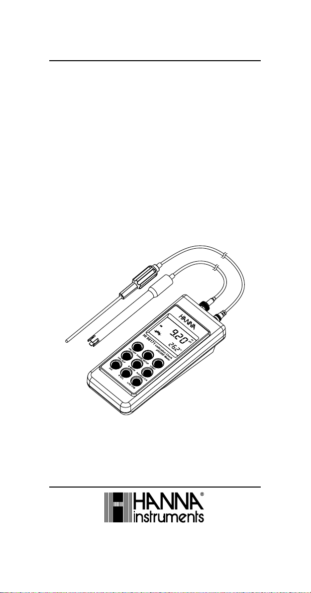
HI 98170 HI 98171
HI 98172
Calibration Check
Waterproof
pH/mV/ISE/Temperature
Meters
www.hannainst.com
1
Page 2

Dear Customer,
Thank you for choosing a Hanna Instruments product.
Please read this instruction manual carefully before using the instruments.
This manual will provide you with the necessary information for correct use of
the instruments, as well as a precise idea of their versatility.
If you need additional technical information, do not hesitate to e-mail us at
tech@hannainst.com or turn to the back cover for our worldwide contact list.
These instruments are in compliance with directives.
WARRANTY
HI 98170, HI 98171 and HI 98172 are guaranteed for two years against
defects in workmanship and materials when used for their intended purpose and
maintained according to instructions. Electrodes and probes are guaranteed for
six months. This warranty is limited to repair or replacement free of charge.
Damage due to accidents, misuse, tampering or lack of prescribed maintenance
is not covered.
If service is required, contact the dealer from whom you purchased the
instrument. If under warranty, report the model number, date of purchase,
serial number and the nature of the problem. If the repair is not covered by
the warranty, you will be notified of the charges incurred. If the instrument is
to be returned to Hanna Instruments, first obtain a Returned Goods Authorization number from the Technical Service department and then send it with
shipping costs prepaid. When shipping any instrument, make sure it is
properly packed for complete protection.
TABLE OF CONTENTS
WARRANTY .................................................................................................................... 2
PRELIMINARY EXAMINATION .......................................................................................... 3
GENERAL DESCRIPTION .................................................................................................. 3
FUNCTIONAL DESCRIPTION ............................................................................................. 5
HI 98170 AND HI 98171 SPECIFICATIONS ....................................................................... 7
HI 98172 SPECIFICATIONS ............................................................................................. 8
OPERATIONAL GUIDE ...................................................................................................... 9
pH CALIBRATION .......................................................................................................... 12
pH BUFFER TEMPERATURE DEPENDENCE ..................................................................... 17
RELATIVE mV CALIBRATION ........................................................................................... 18
ISE CALIBRATION .......................................................................................................... 19
GOOD LABORATORY PRACTICE (GLP) .............................................................................. 22
SETUP ......................................................................................................................... 25
LOGGING ...................................................................................................................... 27
AutoEnd ...................................................................................................................... 29
TEMPERATURE CALIBRATION (for technical personnel only) ........................................... 30
mV CALIBRATION (for technical personnel only) ............................................................ 31
PC INTERFACE .............................................................................................................. 32
BATTERIES RECHARGING/REPLACEMENT ........................................................................ 37
LCD MESSAGE GUIDE .................................................................................................... 39
TEMPERATURE CORRELATION FOR pH SENSITIVE GLASS ................................................ 40
ELECTRODE CONDITIONING & MAINTENANCE ................................................................ 41
TROUBLESHOOTING GUIDE ........................................................................................... 44
ACCESSORIES .............................................................................................................. 45
2
Page 3

PRELIMINARY EXAMINATION
Remove the instrument from the packing material and examine it carefully to
make sure that no damage has occurred during shipping. If there is any
damage, notify your Dealer or the nearest Hanna Customer Service Center.
Each instrument is supplied with:
• HI 1230B Combination double-junction, gel pH Electrode
• HI 7662 stainless steel Temperature Probe with 1 m (3.3') Cable
• pH 4.01 & 7.01 Buffer Solutions (20 mL each)
• 100 mL Plastic Beaker
• 4 x 1.2V AA, 1300 mAh Rechargeable Batteries
• HI 710041 Inductive Recharger
• Instruction Manual
• Rugged carrying case
Note: Save all packing material until you are sure that the instrument
functions correctly. All defective items must be returned in the original
packing with the supplied accessories.
GENERAL DESCRIPTION
HI 98170, HI 98171 and HI 98172 are state-of-the-art, heavy-duty pH
meters, designed to provide laboratory results and accuracy under harsh
industrial conditions.
These instruments are provided with a series of new diagnostic features which
add an entirely new dimension to the measurement of pH, by allowing the
user to dramatically improve the reliability of the measurement:
• 7 memorized buffers (pH 1.68, 4.01, 6.86, 7.01, 9.18, 10.01 and
12.45) for calibration
• pH calibration up to five calibration points
• Custom calibration by entering up to five custom buffers
• Messages on the LCD to make the calibration easy and accurate
• Diagnostic features to alert the user when the electrode needs cleaning
• Outside Calibration Range warning
• Monitoring of the electrode aging
• User-selectable “calibration time out” to remind when a new calibration is
necessary
Hanna Instruments reserves the right to modify the design,
construction and appearance of its products without advance notice.
3
Page 4

Moreover, they offer an extended temperature range from –20 ºC to 120 ºC
(-4 ºF to 248 ºF), using HI 7662 interchangeable probes.
These instruments can also measure with ORP electrodes, thanks to their
capability to measure mV with a resolution up to 0.1 mV.
HI 98172 can also measure with ISE electrodes on ppm scale. The ion charge
selection capability and the ISE calibration in up to five calibration standard
solutions make this instrument very useful for a large range of concentration
solutions measurements.
Other features include:
• Relative mV measurements
• Log on demand (50 samples on each range - pH, mV, ISE)
• Auto Hold feature, to freeze first stable reading on the LCD
• GLP feature, to view last calibration data for pH, Rel mV or ISE
• PC interface
4
Page 5
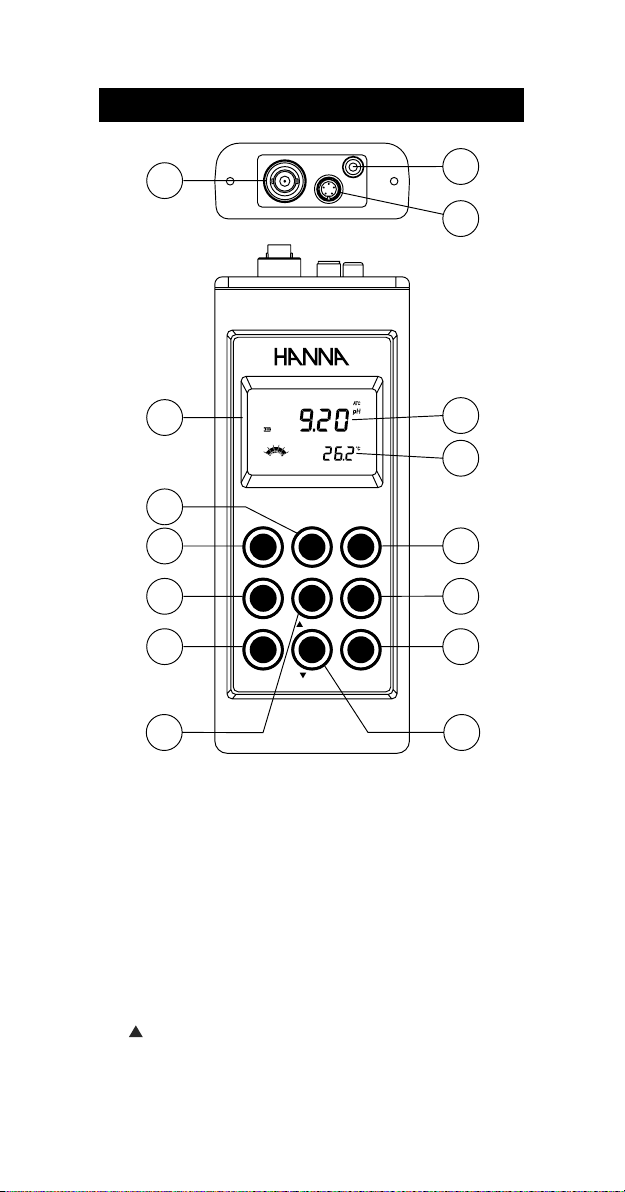
FUNCTIONAL DESCRIPTION
1
2
3
4
15
14
HI 98171
ON / OFF
2nd
Calibration Check
pH/ORP Meter
RANGE SETUP
RCL
13
LIGHT
12
AutoEnd CLRMODECAL GLP
11
LOG CFM
5
6
7
8
109
1) BNC electrode connector.
2) Temperature probe socket.
3) RS232 serial communication connector.
4) Liquid Crystal Display (LCD).
5) RANGE key, to select pH or mV (HI 98171, HI 98172), or ISE (HI 98172).
SETUP key, to enter/exit SETUP mode.
6) ON/OFF key, to turn the instrument ON and OFF.
7) CAL key, to enter/exit calibration mode.
GLP key, to display Good Laboratory Practice information.
8) 2nd key, to select second key function.
9) key, to manually increase temperature or other parameters.
MODE key, to select measurement resolution, 0.1 pH / 0.01 pH (HI
98170), or to toggle between mV and Rel mV (HI 98171, HI 98172).
5
Page 6

10) key, to manually decrease temperature or other parameters.
RCL key, to enter/exit view logged data mode.
11) LOG key, to store measured data.
CFM key, to confirm different values.
12) AutoEnd key, to freeze first stable reading on the LCD.
CLR key, to clear calibration or logged data.
13) LIGHT key, to toggle display backlighting.
14) Secondary LCD.
15) Primary LCD.
6
Page 7
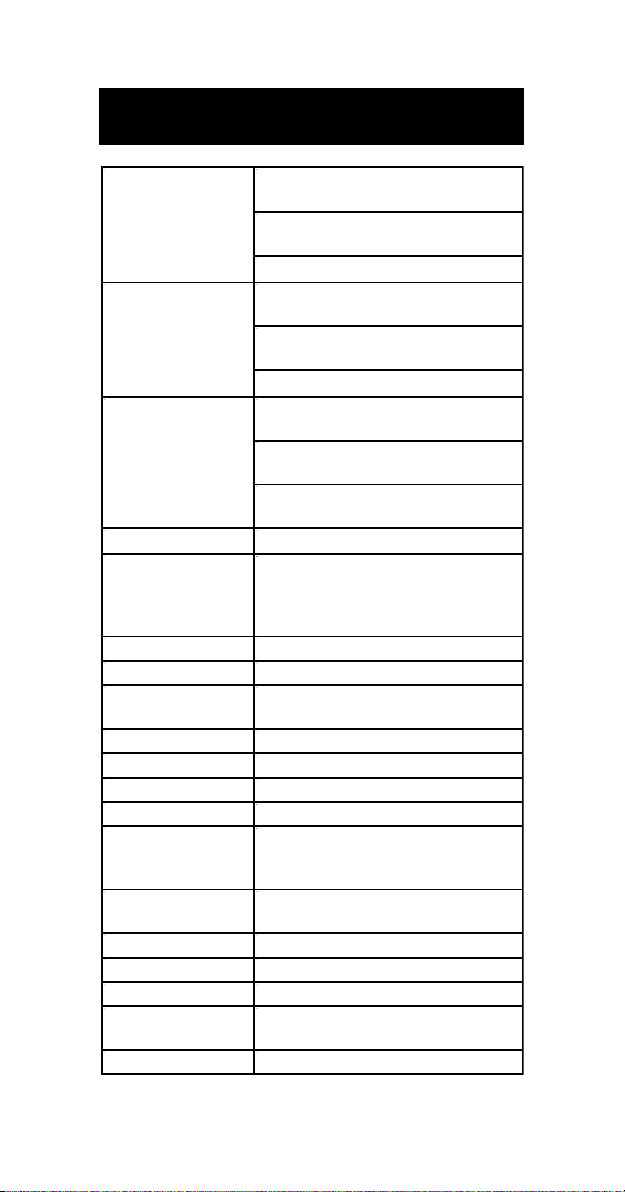
HI 98170 AND HI 98171
SPECIFICATIONS
Hp0.61ot0.2–
Hp00.61ot00.2–
EGNAR
Hp1.0
Hp10.0
NOITULOSER
)Fº1.0(Cº1.0
Hp1.0±
Hp10.0±
YCARUCCA
Fº86/Cº02@
egnartesffoVmleR )ylno17189IH(Vm0002±
noitarbilaCHp
noitarbilaCtesffO Hp1±
noitarbilaCepolS %011ot08morF
noitasnepmocerutarepmeT
edortcelEHp )dedulcni(B0321IH
eborperutarepmeT )dedulcni(2667IH
GOL egnarhcaenoselpmas05,dnamednO
ecnadepmitupnI 01
efiL&epyTyrettaB
ffo-otuA
ecafretniCP 232SRdetalosi-otpo
snoisnemiD )”4.2x1.3x7.7(mm06x08x691
)ylnoretem(thgieW ).zo51(g524
tnemnorivnE
ytnarraW sraey2
21
smho
delbasid
%001HR.xam
)ylno17189IH(Vm9.996±
)ylno17189IH(Vm0002±
)Fº0.842ot0.4–(Cº0.021ot0.02–
)ylno17189IH(Vm1.0
)ylno17189IH(Vm1
)Vm9.996±(Vm2.0±
)Vm0002±(Vm1±
)Fº8.0±(Cº4.0±
)rorreeborpgnidulcxe(
,noitarbilactniop-evifotpU
elbaliavasreffubdradnats7
,)54.21,10.01,81.9,10.7,68.6,10.4,86.1(
sreffubmotsuc5dna
morfcitamotuArolaunaM
)Fº0.842ot0.4–(Cº0.021ot0.02–
seirettabelbaegrahcerAAV2.1x4
tuohtiwesusuounitnocfosruoh002.xorppa
)thgilkcabhtiwsruoh05(thgilkcab
rosetunim03ot1:elbatcelesresU
)Fº221–23(Cº05–0
7
Page 8
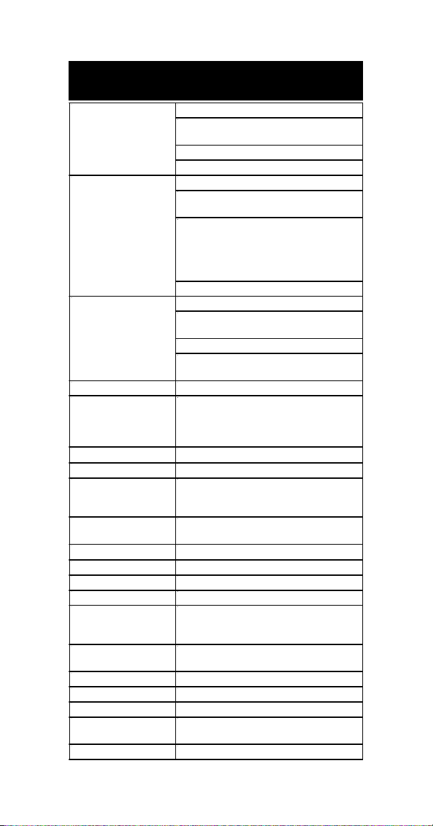
HI 98172
SPECIFICATIONS
EGNAR
NOITULOSER
YCARUCCA
Fº86/Cº02@
egnartesffoVmleR Vm0002±
noitarbilaCHp
noitarbilaCtesffO Hp1±
noitarbilaCepolS %011ot08morF
noitarbilaCESI
noitasnepmocerutarepmeT
edortcelEHp )dedulcni(B0321IH
eborperutarepmeT )dedulcni(2667IH
GOL egnarhcaenoselpmas05,dnamednO
ecnadepmitupnI 01
efiL&epyTyrettaB
ffo-otuA
ecafretniCP 232SRdetalosi-otpo
snoisnemiD )”4.2x1.3x7.7(mm06x08x691
)ylnoretem(thgieW ).zo51(g524
tnemnorivnE
ytnarraW sraey2
Hp00.61ot00.2–
Vm9.996±
Vm0002±
mpp09991ot100.0
)Fº0.842ot0.4–(Cº0.021ot0.02–
Hp10.0
Vm1.0
Vm1
)999.1ot100.0morf(mpp100.0
)99.91ot00.2morf(mpp10.0
)9.991ot0.02morf(mpp1.0
)9991ot002morf(mpp1
)09991ot0002morf(mpp01
)Fº1.0(Cº1.0
Hp10.0±
)Vm9.996±(Vm2.0±
)Vm0002±(Vm1±
.s.f%5.0±
)Fº8.0±(Cº4.0±
)rorreeborpgnidulcxe(
,noitarbilactniop-evifotpU
elbaliavasreffubdradnats7
,)54.21,10.01,81.9,10.7,68.6,10.4,86.1(
sreffubmotsuc5dna
noitarbilactniop-evifotpU
elbaliavasnoitulosdradnats6
)mpp00001,0001,001,01,1,1.0(
morfcitamotuArolaunaM
)Fº0.842ot0.4–(Cº0.021ot0.02–
21
smho
seirettabelbaegrahcerAAV2.1x4
tuohtiwesusuounitnocfosruoh002.xorppa
)thgilkcabhtiwsruoh05(thgilkcab
delbasid
%001HR.xam
rosetunim03ot1:elbatcelesresU
)Fº221–23(Cº05–0
8
Page 9
OPERATIONAL GUIDE
INITIAL PREPARATION
The instrument is supplied complete with rechargeable batteries. Remove the
back cover, unwrap the batteries and install them, while paying attention to
the correct polarity. Proceed with a complete charging process (see page 37).
To prepare the instrument for use, connect the pH electrode and the temperature
probe to the BNC and temperature sockets on the top of the instrument. The
temperature probe is used in conjunction with the pH electrode to utilize the
instrument's ATC capability, but it can also be used independently to take
temperature measurements. If the probe is disconnected, temperature can be
set manually with the ARROW keys (see page 10 for details).
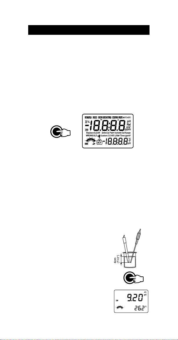
Turn the instrument ON by pressing ON/OFF.
ON / OFF
At start-up the display will show all the used segments for a few seconds (or while
the button is held), followed by the percentage indication of the remaining
battery charge, then enters measurement mode.
After measurement switch the instrument off, clean the electrode and store it with
a few drops of HI 70300 storage solution in the protection cap. Place the instrument
in the battery recharger case and start the recharging process (see page 37).
The auto-off feature turns the instrument off after a set period (default 20 min)
with no button pressed to save battery life. To set another period or to disable
this feature, see SETUP menu on page 25.
The auto-off backlight feature turns the backlight off after a set period (default
1 min) with no buttons pressed. To set another period or to disable this
feature, see SETUP menu on page 25.
pH MEASUREMENTS
To take a pH measurement remove the electrode
protective cap and simply submerge the tip of the
electrode (4cm/1½”) and the temperature probe
into the sample to be tested.
If necessary, press RANGE until the display changes
to the pH mode.
Allow for the electrode to adjust and reading to
stabilize (hourglass symbol turns off).
The LCD will show the pH measurement together
with the temperature of the sample.
9
RANGE SETUP
Page 10
In order to take more accurate pH measurements, make sure that the
instrument is calibrated (see page 12 for details).
It is recommended that the electrode is always kept wet and rinsed thoroughly
with the sample to be measured before use.
The pH reading is directly affected by temperature. In order for the instrument
to measure the pH accurately, temperature must be taken into consideration. If
the sample temperature is different from the temperature at which the pH
electrode was kept, allow a few minutes to reach thermal equilibrium.
To use the instrument's Automatic Temperature Compensation feature, submerge
the temperature probe into the sample as close to the electrode as possible and
wait for a few seconds.
If manual temperature compensation (MTC) is desired, the temperature
probe must be disconnected from the instrument.
The display will show the default temperature of 25 ºC,
the last measured temperature reading, or the last set
temperature, with the “ºC” (or “ºF”) tag blinking.
The “MTC” tag and up & down arrows symbols light up on the LCD to indicate
that the instrument is in MTC mode and the arrow keys can be used to enter
the desired temperature value.
Note: When in MTC the user can press and hold the ARROW keys, and the
instrument will start incrementing / decrementing the temperature value.
The instrument keeps measuring and the display is updated periodically.
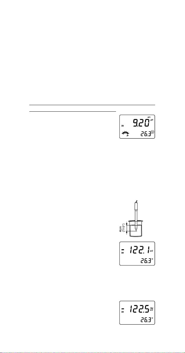
ORP MEASUREMENTS (HI 98171 & HI 98172 only)
To perform ORP measurements, connect an optional ORP electrode (see Accessories
section) to the instrument and turn it ON.
If necessary, enter the mV mode by pressing RANGE
until the display changes to mV.
Submerge the ORP electrode tip (4cm/1½”) into the
sample to be tested and wait a few seconds for the
reading to stabilize.
Measurements within the ±699.9 mV range are
displayed with 0.1 mV resolution, while outside this
range the resolution automatically switches to 1 mV.
The “ATC” (or “MTC”) tag is turned off because mV
readings are not temperature compensated.
For accurate ORP measurements, the surface of the electrode must be clean
and smooth. Pretreatment solutions are available to condition the electrode
and improve its response time (see Accessories section, page 45).
RELATIVE mV MEASUREMENTS (HI 98171 & HI 98172 only)
To enter Relative mV mode, press 2nd then MODE
while in mV measurement mode. The relative mV
reading will be displayed on the primary LCD and the
current temperature value on the secondary LCD.
10
Page 11
The relative mV reading is equal to the difference between the absolute mV input
value and relative mV offset established in the relative mV calibration (see page 18).
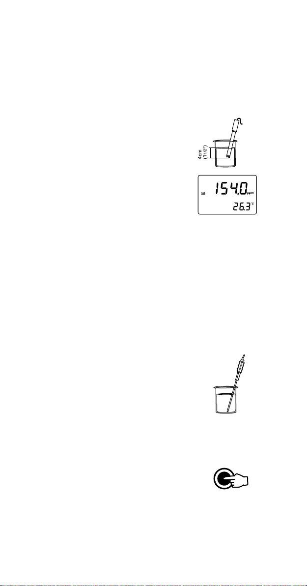
ISE MEASUREMENTS (HI 98172 only)
To perform ion concentration measurements, connect an optional ISE electrode
to the instrument and turn it ON.
If necessary, enter the ISE mode by pressing RANGE
until the display changes to ppm.
Submerge the ISE electrode tip (4cm/1½”) into the
sample to be tested and wait a few seconds for the
reading to stabilize.
The ppm reading will be displayed on the primary LCD
and the current temperature value on the secondary LCD.
The “ATC” (or “MTC”) tag is turned off because ppm
readings are not temperature compensated.
In order to take accurate ISE measurements, make sure that the appropriate ion
charge was set in SETUP menu, according to the ion type that is to be measured
and the instrument was calibrated (see ISE CALIBRATION for details, page 19).
Notes: • When the reading is out of range, the display will flash the closest
full-scale value.
• The instrument will display “----” on the primary LCD if it is not
calibrated. Perform at least a one-point calibration if the ion charge
is -1, 1, -2, 2 or a two-point calibration for the “undF” option
selected in SETUP menu in order to take ISE measurements.
• If using the pH electrode while in mV mode, the instrument will
measure the mV generated by the pH electrode.
TEMPERATURE MEASUREMENTS
Connect the HI 7662 temperature probe to the appropriate socket. Immerse the temperature probe into the
sample and allow the reading on the secondary LCD to
stabilize.
Note: The temperature can be displayed in Celsius degrees (ºC) or in Fahrenheit
degrees (ºF) (see SETUP for details, page 25).
BACKLIGHT FEATURE
The instrument is provided with a Backlight feature,
which can be easily toggled on and off through the
keyboard by pressing LIGHT.
LIGHT
Note: The backlight automatically shuts off after a set period (see SETUP
for details, page 25) with no buttons pressed.
11
Page 12
pH CALIBRATION
It is recommended to calibrate the instrument frequently, especially if high
accuracy is required.
The pH range should be recalibrated:
• Whenever the pH electrode is replaced.
• At least once a week.
• After testing aggressive chemicals.
• When calibration alarm time out is expired - “CAL DUE” tags blink (if
feature is enabled).
• If “Outside Cal Range” message blinks during pH measurement (the
measurement range is not covered by current calibration).
PROCEDURE
The instrument offers a choice of 7 memorized buffers (1.68, 4.01, 6.86, 7.01,
9.18, 10.01 and 12.45 pH) and also allows the user to enter five more pH
values for calibration, “Custom 1” to “Custom 5”. The set custom buffers are
the buffer values at 25 ºC.
When a custom buffer is selected during calibration, the “Custom” tag is
displayed on the LCD and its value can be changed in a ±1.0 pH window,
around the set value, in accordance with current temperature.
For accurate pH measurements, it is recommended to perform a five-point
calibration. However, at least a two-point calibration is suggested.
The instrument will automatically skip the buffers used during calibration and
the buffers which are in a ±0.2 pH window, around one of the calibrated buffers.
• Pour small quantities of selected buffer solutions into clean beakers. For
accurate calibration use two beakers for each buffer solution, the first one for
rinsing the electrode and the second one for calibration.
• Remove the protective cap and rinse the electrode with some of the buffer
solution to be used for the first calibration point.
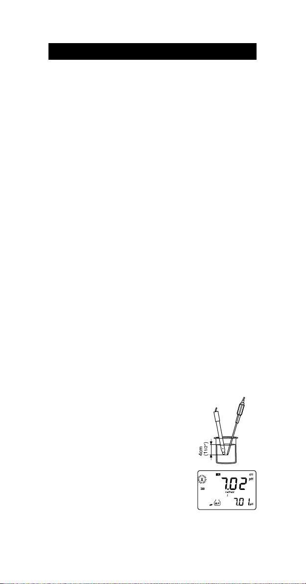
FIVE-POINT CALIBRATION
• Immerse the pH electrode and the temperature
probe approximately 4 cm (1½”) into a buffer
solution of your choice (pH 1.68, 4.01, 6.86,
7.01, 9.18, 10.01, 12.45 or a custom buffer)
and stir gently. The temperature probe should
be close to the pH electrode.
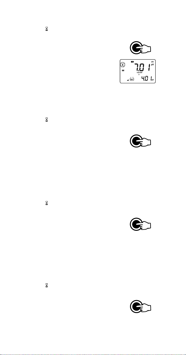
• Press CAL. The instrument will display the measured pH on the primary LCD and “7.01” buffer
on the secondary LCD, together with “CAL” and
“Cal Point 1” tags.
• If necessary, press the ARROW keys to select a different buffer value.
12
Page 13
• The “ ” tag will blink on the LCD until the reading is stable.
• When the reading is stable and close to the
selected buffer, “CFM” tag blinks.
• Press CFM to confirm calibration.
LOG CFM
• The calibrated value is then displayed on the
primary LCD and the secondary LCD will display
the second expected buffer value, together with
“CAL” and “Cal Point 2” tags.
• After the first calibration point is confirmed, immerse the pH electrode and the
temperature probe approximately 4 cm (1½”) into the second buffer solution
and stir gently. The temperature probe should be close to the pH electrode.
• If necessary, press the ARROW keys to select a different buffer value.
• The “ ” tag will blink on the LCD until the reading is stable.
• When the reading is stable and close to the selected buffer, “CFM” tag blinks.
• Press CFM to confirm calibration.
• The calibrated value is then displayed on the
primary LCD and the secondary LCD will display
LOG CFM
the third expected buffer value.
• After the second calibration point is confirmed, immerse the pH electrode
and the temperature probe approximately 4 cm (1½”) into the third
buffer solution and stir gently. The temperature probe should be close to
the pH electrode.
• If necessary, press the ARROW keys to select a different buffer value.
• The “ ” tag will blink on the LCD until the reading is stable.
• When the reading is stable and close to the selected buffer, “CFM” t ag blinks.
• Press CFM to confirm calibration.
• The calibrated value is then displayed on the
primary LCD and the secondary LCD will display
LOG CFM
the fourth expected buffer value.
• After the third calibration point is confirmed, immerse the pH electrode
and the temperature probe approximately 4 cm (1½”) into the fourth
buffer solution and stir gently. The temperature probe should be close to
the pH electrode.
• If necessary, press the ARROW keys to select a different buffer value.
• The “ ” tag will blink on the LCD until the reading is stable.
• When the reading is stable and close to the selected buffer, “CFM” t ag blinks.
• Press CFM to confirm calibration.
• The calibrated value is then displayed on the
primary LCD and the secondary LCD will display
LOG CFM
the fifth expected buffer value.
13
Page 14
• After the fourth calibration point is confirmed, immerse the pH electrode and the
temperature probe approximately 4 cm (1½”) into the fifth buffer solution and
stir gently. The temperature probe should be close to the pH electrode.
• If necessary, press the ARROW keys to select a different buffer value.
• The “ ” tag will blink on the LCD until the reading is stable.
• When the reading is stable and close to the selected buffer, “CFM” t ag blinks.
• Press CFM to confirm calibration.
• The instrument stores the calibration values and
returns to normal measurement mode.
LOG CFM
FOUR, THREE or TWO-POINT CALIBRATION
• Proceed as described in “FIVE-POINT CALIBRATION” section.
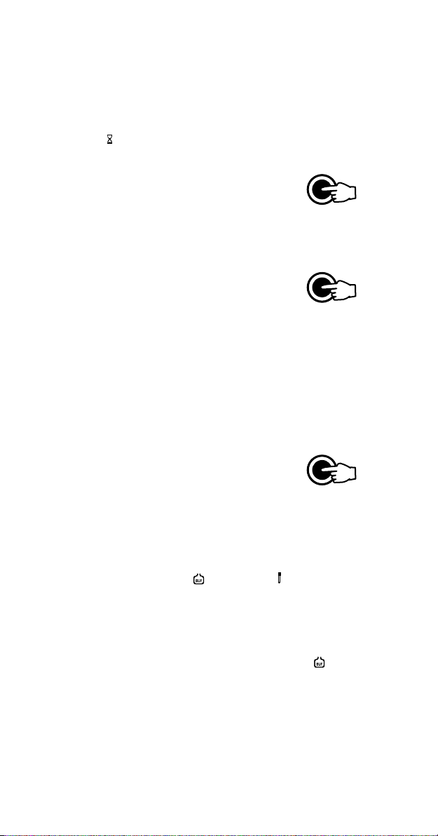
• Press CAL after the appropriate accepted calibration
point. The instruments will return to measurement
mode and will memorize the calibration data.
CAL GLP
ONE-POINT CALIBRATION
Two SETUP selectable options are available for one-point calibration: “Pnt”
and “OFFS”.
If the “Pnt” option is selected, the adjacent slopes will be reevaluated.
If the “OFFS” option is selected, an electrode offset correction is performed
keeping unchanged the existing slopes.
• Proceed as described in “FIVE-POINT CALIBRATION” section.
• Press CAL after the first calibration point was
confirmed. The instruments will memorize the
one-point calibration data and will return to
CAL GLP
measurement mode.
Notes: • Press 2nd then MODE to toggle between pH buffer and temperature
reading during calibration.
• If the value measured by the instrument is not close to the selected
buffer, “WRONG” “ ” and “WRONG” “ ” tags will blink alternately. In this case check if the correct buffer has been used, or
regenerate the electrode by following the Cleaning Procedure (see
page 43). If necessary, change the buffer or the electrode.
• If the buffer temperature or the manual temperature exceeds
the temperature limits of the buffer, “WRONG” “ ” tags and
temperature reading will blink.
• If “WRONG” tag and “OLd” message on the secondary LCD are
displayed blinking, an inconsistency between new and previous (old)
calibration is detected. Clear old calibration parameters and proceed
with calibration from the current calibration point. The instrument will
keep all confirmed values during current calibration.
14
Page 15
• With one-point calibration there is no “Condition” and only the
frame is shown. Calibration time out is active.
• Each time a buffer is confirmed, the new calibration parameters
replace the old calibration parameters of the corresponding buffer.
If current confirmed buffer has no correspondence in the existing
stored calibration and this is not full, the current buffer is added to
the existing stored calibration.
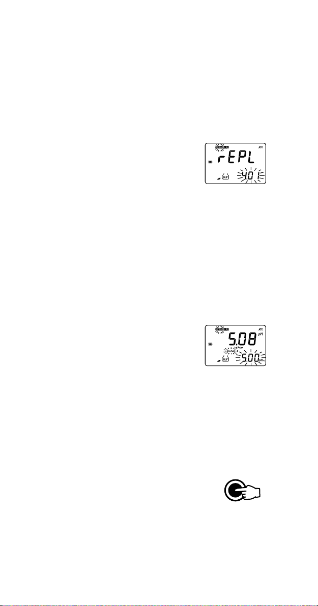
If the existing stored calibration is full (five
calibration points), and after confirming
the calibration point, the instrument will
ask which buffer will be replaced by current
buffer.
Press the ARROW keys to select another buffer to be replaced.
Press CFM to confirm the buffer that will be replaced.
Press CAL to leave replace mode. In this case, the buffer will not
be memorized.
Note: The replaced buffer is not removed from calibration list and it can be
selected for the next calibration points.
WORKING WITH CUSTOM BUFFERS
If at least one custom buffer was set in SETUP menu, it can be selected for
calibration by pressing the ARROW keys. The “CUSTOM” tag will be displayed
blinking on the LCD.
Press 2nd then SETUP if you want to adjust the buffer
value in accordance with current temperature. The
buffer value, displayed on the secondary LCD, will
start blinking.
Use the ARROW keys to change the buffer value.
After about 5 seconds you performed the last change, the buffer value is
updated. Press 2nd then SETUP if you want to change it again.
Notes: • Custom buffer value can be adjusted in a ±1.00 pH window,
around the set value.
• If you want to return to the set custom buffer value, simply press the
ARROW keys (UP then DOWN) to select again the custom buffer.
CLEAR CALIBRATION
Press 2nd then CLR in any moment during calibration.
The “CLr ALL” message will be displayed on the LCD
along with “OLD” tag.
AutoEnd CLR
All old calibrations, starting with current selected buffer are cleared and the
instrument continues calibration.
Note: If CLR is pressed during the first calibration point, the instrument
returns to measurement mode.
15
Page 16
CONDITION
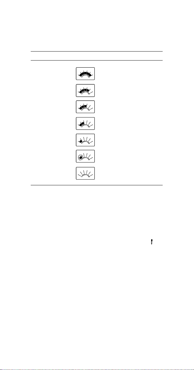
The display is provided with a 5-dot bargraph (unless the feature is disabled)
which gives an indication of the electrode status after calibration as follows:
Bargraph indication Condition value
All 5 dots steady 81 to 100% of life
4 dots steady 61 to 80%
3 dots steady 41 to 60%
2 dots steady 21 to 40%
1 dot steady 1 to 20%
1 dot blinking 0%
Only frame is ON No info available
The “condition” bargraph remains active until the end of the calibration day.
Note: The electrode condition is evaluated only if current calibration includes
at least two.
CLEAN ELECTRODE
Each time pH calibration is performed, the instrument internally compares the
new calibration with the one previously stored.
When this comparison indicates a significant difference, the “CLEAN” “ ” tags
blink on the LCD to advise the user that the pH electrode may need to be cleaned
(see ELECTRODE CONDITIONING & MAINTENANCE section for details, page 41).
After cleaning, perform a new calibration.
Note: If the calibration data are cleared, the comparison is done with the
default values.
16
Page 17

pH BUFFER TEMPERATURE
5
1
1
DEPENDENCE
The temperature has an effect on pH. The calibration buffer solutions are
affected by temperature changes to a lesser degree than normal solutions.
During calibration the instrument will automatically calibrate to the pH value
corresponding to the measured or set temperature.
PMET SREFFUBHp
Cº Fº 86.1 10.4 68.6 10.7 81.9 10.01
0 23 76.1 10.4 89.6 31.7 64.9 23.01 83.31
5 14 76.1 00.4 59.6 01.7 93.9 42.01 81.31
01 05 76.1 00.4 29.6 70.7 33.9 81.01 99.21
51 95 76.1 00.4 09.6 50.7 72.9 21.01 08.21
02 86 86.1 00.4 88.6 30.7 22.9 60.01 26.21
52 77 86.1 10.4 68.6 10.7 81.9 10.01 54.21
03 68 86.1 20.4 58.6 00.7 41.9 69.9 92.21
53 59 96.1 30.4 48.6 99.6 11.9 29.9 31.21
04 401 96.1 40.4 48.6 89.6 70.9 88.9 89.11
54 311 07.1 50.4 38.6 89.6 40.9 58.9 38.11
05 221 17.1 60.4 38.6 89.6 10.9 28.9 07.11
55 131 27.1 80.4 48.6 89.6 99.8 97.9 75.11
06 041 27.1 90.4 48.6 89.6 79.8 77.9 44.11
56 941 37.1 11.4 48.6 99.6 59.8 67.9 23.11
07 851 47.1 21.4 58.6 99.6 39.8 57.9
57 761 67.1 41.4 68.6 00.7 19.8 47.9 01.11
4.21
2.11
08 671 77.1 61.4 78.6 10.7 98.8 47.9 00.11
58 581 87.1 71.4 78.6 20.7 78.8 47.9
09 491 97.1 91.4 88.6 30.7 58.8 57.9 28.01
59 302 18.1 02.4 98.6 40.7 38.8 67.9 37.01
9.01
During calibration the instrument will display the pH buffer value at 25 ºC.
17
Page 18

RELATIVE mV CALIBRATION
(HI 98171 & HI 98172)
• Press CAL when the instrument is in RELATIVE
mV measurement mode. The relative mV value
is displayed on the primary LCD and the absolute
mV value on the secondary LCD.
• Use the ARROW keys if you want to change the displayed relative mV value.
MODE
RCL
• When the reading is stable, in mV range and the Relative mV offset is
inside the offset window (±2000 mV), “CFM” tag blinks.
• Press CFM to confirm relative mV calibration. The instrument will return to
measurement mode.
• If the absolute mV reading is out of range or the Relative mV offset is out
of the offset window, “WRONG” tag will blink. Change the input value or
the Relative mV value on the primary LCD to complete the calibration
process.
18
Page 19

ISE CALIBRATION (HI 98172 only)
It is recommended to calibrate the instrument frequently, especially if high
accuracy is required.
The ppm range should be recalibrated:
• Whenever the ISE electrode is replaced.
• When the ion charge is changed in SETUP menu.
• At least once a week.
• After testing agressive chemicals.
• When calibration alarm time out is expired - “CAL DUE” tags blink (if
feature is enabled).
Due to electrode conditioning time, the electrode must be kept immersed a few
seconds to stabilize. The user will be guided step by step during calibration
with easy to follow tags on the LCD. This will make the calibration a simple and
error-free procedure.
PROCEDURE
Select the proper ion charge in SETUP menu (see SETUP for details, page 25).
Note: If “undF” option is selected in SETUP menu, calibration must be performed
in at least two points, otherwise “----” message will be displayed on the LCD
if exiting calibration after confirming the first used standard.
Pour small quantities of the buffer solutions into clean beakers. If possible, use
plastic beakers to minimize any EMC interferences.
For accurate calibration and to minimize cross-contamination, use two beakers for
each buffer solution. One for rinsing the electrode and one for calibration.
The instrument offers a choice of six memorized standard solutions: 0.1, 1, 10,
100, 1000, 10000 ppm and calibration up to five points.
Remove the protective cap from the ISE electrode.
FIVE-POINT CALIBRATION
• Immerse the ISE electrode approximately 4 cm
(1½”) into the less concentrated standard solution
and stir gently.
• Press CAL. The primary LCD will display the ppm
value using the current offset and slope. The “CAL”
and “Cal Point 1” tags will appear and “0.100” ppm
standard will be displayed on the secondary LCD.
• If necessary, press the ARROW keys to select a different standard value.
• The “ ” tag will blink on the LCD until the reading is stable.
• When the reading is stable and close to the selected standard, the “CFM” tag
blinks.
• Press CFM to confirm calibration.
LOG CFM
19
Page 20

• The calibrated value will be displayed on the
primary LCD and the second expected standard
value on the secondary LCD, together with “CAL”
and “Cal Point 2” tags.
Note: The instrument will automatically skip the standard solution used for
the first point.
• After the first calibration point is confirmed, immerse the ISE electrode
approximately 4 cm (1½”) into the second calibration solution.
• If necessary, press the ARROW keys to select a different standard value.
• The “ ” tag will blink on the LCD until the reading is stable.
• When the reading is stable and close to the selected standard, the “CFM”
tag blinks.
• Press CFM to confirm calibration.
• The calibrated value will be displayed on the
LOG CFM
primary LCD and the third expected standard
value on the secondary LCD.
• After the second calibration point is confirmed, immerse the ISE electrode
approximately 4 cm (1½”) into the third calibration solution.
• If necessary, press the ARROW keys to select a different standard value.
• The “ ” tag will blink on the LCD until the reading is stable.
• When the reading is stable and close to the selected standard, the “CFM”
tag blinks.
• Press CFM to confirm calibration.
• The calibrated value will be displayed on the
LOG CFM
primary LCD and the fourth expected standard
value on the secondary LCD.
• After the third calibration point is confirmed, immerse the ISE electrode
approximately 4 cm (1½”) into the fourth calibration solution.
• If necessary, press the ARROW keys to select a different standard value.
• The “ ” tag will blink on the LCD until the reading is stable.
• When the reading is stable and close to the selected standard, the “CFM”
tag blinks.
• Press CFM to confirm calibration.
• The calibrated value will be displayed on the
LOG CFM
primary LCD and the fifth expected standard
value on the secondary LCD.
• After the fourth calibration point is confirmed, immerse the ISE electrode
approximately 4 cm (1½”) into the fifth calibration solution.
• If necessary, press the ARROW keys to select a different standard value.
• The “ ” tag will blink on the LCD until the reading is stable.
20
Page 21

• When the reading is stable and close to the selected standard, the “CFM”
tag blinks.
• Press CFM to confirm calibration. The instrument
stores the calibration value and returns to normal
measurement mode.
LOG CFM
Notes: • If the new slope is out of slope window or the mV value is out of mV
range (±2000), “WRONG” tag will blink. In this case check if
the correct standard has been used, or refresh the electrode by
following the Cleaning Procedure (see page 43). If necessary,
change the standard or the electrode.
• Slope window is between ±20 mV and ±120 mV if ion charge
is not specified (undF selected in SETUP menu) or between 50%
and 120% of default slope for the corresponding ion charge.
Default slope value (mV/decade):
–59.16 (monovalent anion) - ion charge is –1
59.16 (monovalent cation) - ion charge is 1
–29.58 (divalent anion) - ion charge is –2
29.58 (divalent cation) - ion charge is 2
100 - ion charge is “undF”
• Press 2nd then CLR in any moment during calibration. The “CLr ALL” message
will be displayed on the LCD along with
AutoEnd CLR
”OLD” tag.
All old calibrations, starting with current selected standard are
cleared and the instrument continues calibration.
• The instrument will display “----” on the primary LCD if it is not
calibrated or after all calibrations are cleared.
Note: If CLR is pressed during the first calibration point, the instrument
returns to measurement mode.
• Press 2nd then MODE to display the temperature
reading on the LCD during calibration.
MODE
FOUR, THREE, TWO or ONE-POINT CALIBRATION
• Proceed as described in “FIVE-POINT CALIBRATION” section.
• Press CAL after the appropriate accepted calibration
point. The instruments will return to measurement
mode and will memorize the calibration data.
CAL GLP
21
Page 22

GOOD LABORATORY PRACTICE (GLP)
GLP is a set of functions that allows storage and retrieval of data regarding the
maintenance and status of the electrode.
All data regarding pH, Rel mV or ISE calibration is stored for the user to review
when necessary.
EXPIRED CALIBRATION
The instrument is provided with a real time clock (RTC), in order to monitor the
time elapsed since the last pH calibration.
The real time clock is reset every time the instrument is calibrated and the
“expired calibration” status is triggered when the instrument detects a
calibration time out. The “CAL” “DUE” tags will start blinking to warn the
user that the instrument should be recalibrated.
The calibration time out can be set (see SETUP for details, page 25) from OFF
(function disabled) to 7 days.
For example, if a 4 days time out has been selected, the instrument will issue
the alarm exactly 4 days after the last calibration.
However, if at any moment the expiration value is changed (e.g. to 5 days),
then the alarm will be immediately recalculated and appear 5 days after the
last calibration.
Notes: • When the instrument is not calibrated or calibration is cleared
(default values loaded) there is no “expired calibration”, and the
display always shows the “CAL” “DUE” tags blinking.
• When an abnormal condition in the RTC is detected, the instrument
forces the “expired calibration” status.
LAST pH CALIBRATION DATA
The last pH calibration data is stored automatically after a successful calibration.
To view the pH calibration data, press 2nd then GLP when the instrument is
in pH measurement mode.
The instrument will display the time (hh:mm) of the
last calibration.
Press the ARROW keys to view the next calibration
parameter (pressing the key):
• The date (mm.dd.yyyy) of the last calibration.
• The pH calibration offset.
22
Page 23

• The pH calibration slope (the GLP slope is the
average of the calibration slopes; the percentage
is referred to the ideal value of 59.16 mV/pH).
• The calibration buffers in calibrating order, for the
last calibration.
The first pH calibration buffer:
The second pH calibration buffer:
The third pH calibration buffer:
The fourth pH calibration buffer:
The fifth pH calibration buffer:
Notes: • The “OLd” message displayed beside the pH value means that this
buffer was not used during last calibration. Press 2nd then SETUP
if you want to see calibration date (or time, if old calibration was
performed in the same day with current calibration). In this case,
the calibration buffer number is not displayed on the LCD.
• If “no bUF” message appears on the LCD, the instrument informs
you that calibration was performed in less than five points.
• The Calibration Alarm Time Out status.
If disabled,
or the number of days until the calibration alarm will be displayed (e.g.
5 days), or from the time calibration expired (e.g. –3 days).
• The instrument ID.
23
Page 24

LAST RELATIVE mV CALIBRATION DATA
Last Relative mV calibration data is stored automatically after a successful
calibration.
To view the Relative mV calibration data, press 2nd then GLP while in
Relative mV measurement mode.
The instrument will display the Relative mV GLP information.
• The time (hh:mm:ss) of the last Rel mV calibration as in pH GLP mode.
Press the ARROW keys to view the next calibration parameter (pressing the
key):
• The Relative mV calibration date as in pH GLP mode.
• The Relative mV calibration offset as in pH GLP mode.
• The instrument ID as in pH GLP mode.
Notes: • Press 2nd then GLP at any moment and the instrument will
return to measurement mode.
• If calibration has not been performed, the instrument displays “no
CAL” message blinking.
LAST ISE CALIBRATION DATA
Last ISE calibration data is stored automatically after a successful calibration.
To view the ISE calibration data, press 2nd then GLP while in ISE measurement mode.
The instrument will display the time (hh:mm:ss) of the last calibration as in pH
GLP mode.
Press the ARROW keys to view the next calibration parameter (pressing the
key):
• The ISE calibration date as in pH GLP mode.
• The ISE calibration slope (mV/decade).
• The calibration standards in calibrating order, for
the last calibration.
The first calibration standard:
The second calibration standard:
The third calibration standard:
24
Page 25

The fourth calibration standard:
The fifth calibration standard:
Notes: • The “OLd” message displayed beside the ppm value means that
this standard was not used during last calibration. Press 2nd then
SETUP if you want to see calibration date (or time, if old calibration
was performed in the same day with current calibration). In this
case, the calibration standard number is not displayed on the LCD.
• If “no bUF” message appears on the LCD, the instrument informs
you that calibration was performed in less than five points.
• The Calibration Alarm Time Out status and the Instrument ID as in pH GLP mode.
SETUP
Setup mode allows viewing and modifying the following parameters:
• Calibration Alarm Time Out (pH and ISE range only)
• One-point calibration behaviour (pH range only)
• Custom buffers (1 to 5) (pH range only)
• Ion charge (ISE range only)
• Current Date (mm.dd.yyyy)
• Current Time (hh:mm)
• Beep Status
• Baud Rate (serial communication)
• Command prefix (serial communication)
• Instrument ID
• Auto power off
• Auto-off backlight
• Temperature Unit
To enter SETUP mode, press 2nd then SETUP while the instrument is in
measurement mode.
Select the desired setup parameter using the ARROW keys.
Press CAL if you want to change the item value. The
selected item (e.g. hour, in setting up the correct
time) will start blinking.
Press the ARROW keys to change the displayed value.
25
Page 26

If there is another item to be set (e.g. minutes), press
2nd then MODE. The other item will start blinking.
Press the ARROW keys to change the displayed
value.
Press CFM to confirm or CAL to escape.
Press the ARROW keys to select the next/previous parameter.
Press 2nd then SETUP to exit SETUP menu at any time.
The following table lists the SETUP parameters, their valid values range and
the factory settings (default):
Item Description Valid values Default
CAL DUE Alarm Time Out OFF or 1 to 7 days OFF
Custom 1-5 Custom Buffer 1 to5 no or -2.00 to 16.00 pH no
1Pnt One-point cal. behaviour Pnt or OFFS Pnt
IonCG Ion Charge undF or -2; -1; 1; 2 undF
Time (hh:mm) 00:00 to 23:59 00:00
Date Date (mm.dd.yyyy) 01.01.2000 to 12.31.2099 01.01.2005
bEEP Beep Status ON/OFF OFF
bAUd Baud Rate 600; 1200; 2400; 4800; 9600 2400
PrEF Command Prefix 0 to 47 16
In Id Instrument ID 0000 to 9999 0000
LI GH Auto-off backlight OFF or 1, 5, 10 min 1
A.OFF Auto power off OFF or 5, 10, 20, 60 min 20
tEMP Temperature Unit º C or ºF ºC
Notes: • The custom buffers can be set only with 0.01 pH resolution, at 25 º C.
Press 2nd then MODE repeatedly while in custom buffer setting
mode until the closest buffer value to the desired custom buffer to be
set is displayed on the LCD. If selecting “no” option, the selected
custom buffer is removed. After removing one custom buffer, the
custom buffer list is reordered.
• To select the right ion charge, different ion types and their charge
are presented in the table below:
EGRAHCNOI sepytNOI
2– )snoinatnelavid( OC,S
1– )snoinatnelavonom( OlC,NCS,NC,I,rB,lC,F
1 )snoitactnelavonom( HN,gA,K,aN,H
2 )snoitactnelavid( bP,uC,dC,aB,aC,gM
Fdnu noidenifednu
3
ON,
4
3
4
26
Page 27

LOGGING
This feature allows the user to log pH, Rel mV or ISE measurements, together
with corresponding mV and temperature automatically. All logged data can
be transferred to a PC through the RS232 port.
The maximum logging space is 150 record locations (50 records on each range).
LOGGING THE CURRENT DATA
To store the current reading into memory, press LOG
while in measurement mode.
The instrument will display the current date (mm.dd)
on the primary LCD, the record number on the secondary
LCD, together with “LOG” tag and then the free
locations number.
If there are less than 6 memory locations remaining,
the “Lo” message will blink for a few seconds to alert
the user, and then the free locations number is displayed
on the LCD.
If the LOG space is full, “FULL LOC” message will be
displayed on the LCD for a few seconds with “LOG”
tag blinking, and then ”FrEE 0” message.
The instrument returns to normal measurement mode.
VIEW LOGGED DATA
Press 2nd then RCL to retrieve the information stored
while in measurement mode for the specific range.
LOG CFM
RCL
If no data were logged, the instrument will display
“no rEC” message blinking.
Otherwise, the instrument will display the memorized data, in according with
the selected range:
• If RCL mode was invoked while the instrument was
in pH range: the last pH memorized reading on
the primary LCD and the record number on the
secondary LCD.
• If RCL mode was invoked while the instrument
was in mV or Rel mV range: the last Rel mV
memorized reading on the primary LCD and the
record number on the secondary LCD.
27
Page 28

• If RCL mode was invoked while the instrument
was in ISE range: the last ppm memorized
reading on the primary LCD and the record
number on the secondary LCD.
Press 2nd then SETUP while in RECALL mode and the instrument will toggle
between the record number on the secondary LCD and the current displayed
information. Use the ARROW keys to select another record.
Press 2nd then MODE and the instrument will display the next logged
parameter as shown in the table below:
Parameter Primary LCD Secondary LCD
mV mV reading Temperature
DATE Month & day Year
TIME Hour & minutes Seconds
OFFSET Offset value OFFS
SLOPE Slope value SLP
Note: If in Rel mV RECALL mode regarding the slope, the instrument will
display “----” message on the primary LCD.
Last displayed parameter is “dEL” message on the
primary LCD and the record number on the secondary
LCD.
Note: Pressing 2nd then SETUP the instrument toggles between record
number and all records.
• Press 2nd then CLR to delete the selected or all records. The “nuLL”
message will be displayed on the primary LCD for the selected record.
• If “dEL ALL” option was selected, all logged data are deleted and the
instrument returns to measurement mode.
Press 2nd then RCL at any time to return to measurement mode.
28
Page 29

AutoEnd
To freeze the first stable reading on the LCD press
AutoEnd while the instrument is in measurement
mode.
The ”HOLD” tag will be displayed blinking on the
LCD until the reading will stabilize.
When the reading is stable, the “HOLD” tag stops blinking and the reading
is frozen on the LCD.
Press AutoEnd again to return to normal measurement mode.
Note: Pressing 2nd then MODE the instrument will skip to the displayed range,
without leaving AutoEnd mode. The LOG key also holds AutoEnd mode.
Pressing2nd then SETUP, GLP or RCL, the instrument leaves AutoEnd
mode and performs the selected function.
AutoEnd CLR
29
Page 30

TEMPERATURE CALIBRATION
(for technical personnel only)
All the instruments are factory calibrated for temperature.
Hanna’s temperature probes are interchangeable and no temperature
calibration is needed when they are replaced.
If the temperature measurements are inaccurate, temperature recalibration
should be performed.
For an accurate recalibration, contact your dealer or the nearest Hanna
Customer Service Center, or follow the instructions below.
• Prepare a vessel containing ice and water and another one containing hot
water (at approximately 50 ºC or 122 ºF). Place insulation material around
the vessels to minimize temperature changes.
• Use a calibrated thermometer with a resolution of 0.1 ºC as a reference
thermometer. Connect the HI 7662 temperature probe to the appropriate
socket.
• With the instrument off, press and hold down the SETUP & keys,
then power on the instrument. The “CAL” tag will appear and the
secondary LCD will show 0.0 ºC. The primary LCD will display the
measured temperature or the ”----” message, if the measured temperature
is out of range.
• Immerse the temperature probe into the vessel with ice and water as close
as possible to the reference thermometer. Allow a few seconds for the probe
to stabilize.
• Use the ARROW keys to set the reading on the secondary LCD to that of ice
and water, measured by the reference thermometer. When the reading is
stable and close to the selected calibration point, “CFM” tag will blink.
MODE
RCL
• Press CFM to confirm. The secondary LCD will
display 50.0 ºC.
LOG CFM
• Immerse the temperature probe into the second vessel as close as possible to
the reference thermometer. Allow a few seconds for the probe to stabilize.
• Use the ARROW keys to set the reading on the secondary LCD to that of
the hot water.
• When the reading is stable and close to the selected calibration point,
“CFM” tag will blink.
• Press CFM to confirm. The instrument returns to
measurement mode.
LOG CFM
30
Page 31

Note: If the reading is not close to the selected calibration point, “WRONG” tag
will blink. Change the temperature probe and restart calibration.
mV CALIBRATION
(for technical personnel only)
All the instruments are factory calibrated for mV.
Hanna’s ORP electrodes are interchangeable and no mV calibration is
needed when they are replaced.
If the mV measurements are inaccurate, mV recalibration should be performed.
For an accurate recalibration, contact your dealer or the nearest Hanna
Customer Service Center, or follow the instructions below.
A two-point calibration can be performed at 0 mV and 1800 mV.
• Attach to the BNC connector a mV simulator with an accuracy of ±0.1 mV.
• With the instrument off, press and hold down the Light & LOG keys,
then power on the instrument. The “CAL” tag will appear and the
secondary LCD will show 0.0 mV.
• Set 0.0 mV on the simulator.
When the reading is stable and close to the selected calibration point,
“CFM” tag will blink.
• Press CFM to confirm. The secondary LCD will display 1800 mV.
• Set 1800.0 mV on the simulator.
When the reading is stable and close to the selected calibration point,
“CFM” tag will blink.
• Press CFM to confirm. The instrument returns to measurement mode.
Notes: • If the reading is not close to the selected calibration point, “WRONG”
tag will blink. Verify calibration condition or contact your vendor
if you can not calibrate.
• Press CAL in any moment of the calibration process. The instrument
will return to measurement mode.
31
Page 32

PC INTERFACE
Data transmission from the instrument to the PC can be done with the HI 92000
Windows® compatible software (optional). HI 92000 also offers graphing and
on-line help feature.
Data can be exported to the most popular spreadsheet programs for further analysis.
To connect your instrument to a PC, use the optional Hanna HI 920011 (5 to
9 pin) cable connector. Make sure that your instrument is switched off and
plug one connector to the instrument RS232C socket and the other to the
serial port of your PC.
Notes: • Other cables than HI 920011 may use a different configuration. In this
case, communication between instrument and PC may not be possible.
• If you are not using Hanna Instruments HI 92000 software,
please see the following instructions.
SENDING COMMANDS FROM PC
It is also possible to remotely control the instrument with any terminal program.
Use HI 920011 cable to connect the instrument to a PC, start the terminal
program and set the communication options as follows: 8, N, 1, no flow control.
COMMAND TYPES
To send a command to the instrument follow the next scheme:
<command prefix> <command> <CR>
where: <command prefix> is a selectable ASCII character
between 0 and 47 (default 16).
<command> is the command code.
Note: Either small or capital letters can be used.
SIMPLE COMMANDS
RNG Is equivalent to pressing RANGE
MOD Is equivalent to pressing MODE
CAL Is equivalent to pressing CAL
CFM Is equivalent to pressing CFM
UPC Is equivalent to pressing the UP arrow key
DWC Is equivalent to pressing the DOWN arrow key
LOG Is equivalent to pressing LOG
RCL Is equivalent to pressing RCL
SET Is equivalent to pressing SETUP
CLR Is equivalent to pressing CLR
OFF Is equivalent to pressing OFF
AED Is equivalent to pressing AutoEnd
32
Page 33

CHR xx Change the instrument range according with the parameter
value (xx):
• xx=01 pH range/0.01 resolution
• xx=02 pH range/0.1 resolution (HI 98170, HI 98171)
• xx=03 mV range
• xx=04 Relative mV range
• xx=05 ISE range (HI 98172)
The instrument will answer for these commands with:
<STX> <answer> <ETX>
where: <STX> is 02 ASCII code character (start of text)
<ETX> is 03 ASCII code character (end of text)
<answer>:
<ACK> is 06 ASCII code character (recognized command)
<NAK> is 21 ASCII code character (unrecognized command)
<CAN> is 24 ASCII code character (corrupted command)
COMMANDS REQUIRING AN ANSWER
The instrument will answer for these commands with:
<STX> <answer> <checksum> <ETX>
where the checksum is the bytes sum of the answer string sent as 2 ASCII characters.
All the answer messages are with ASCII characters.
RAS Causes the instrument to send a complete set of readings in
according with the current range:
• pH and temperature reading (HI 98170), and mV
reading (HI 98171) on pH range.
• Rel mV, absolute mV and temperature reading on Rel
mV range (HI 98171, HI 98172).
• ppm, mV and temperature reading on ppm range
(HI 98172).
The answer string contains:
• Meter mode (2 chars):
• 01 - pH range (0.01 resolution)
• 02 - pH range (0.1 resolution)
• 03 - mV range
• 04 - Rel mV range
• 05 - ISE range
• Meter status (2 chars of status byte): represents a 8 bit
hexadecimal encoding.
33
Page 34

• 0x10 - temperature probe is connected
• 0x01 - new GLP data available
• 0x02 - new SETUP parameter
• Reading status (2 chars): R - in range, O - over range, U -
under range. First character corresponds to the appropriate
range reading. Second character corresponds to mV reading.
• Primary reading (corresponding to the selected range) -
7 ASCII chars, including sign and decimal point.
• Secondary reading (only when primary reading is not
mV) - 7 ASCII chars, including sign and decimal point.
• Temperature reading - 7 ASCII chars, with sign and two
decimal points, always in ºC.
MDR Requests the instrument model name and firmware code (16 ASCII
chars).
GLP Requests the calibration data record.
The answer string contains:
• GLP status (1 char): represents a 4 bit hexadecimal encoding.
• 0x01 - pH calibration available
• 0x02 - Rel mV calibration available
• 0x04 - ISE calibration available
• pH calibration data (if available), which contains:
• the number of calibrated buffers (1 char)
• the ion charge, with sign (2 chars)
• the offset, with sign and decimal point (7 chars)
• the average of slopes, with sign and decimal point (7 chars)
• the calibration time, yymmddhhmmss (12 chars)
• buffers information (for each buffer)
• type (1 char): 0 - standard, 1 - custom
• status (1 char): N (new) - calibrated in last calibration;
O (old) - from an old calibration.
• warnings during calibration (2 chars): 00 - no
warning, 04 - Clean Electrode warning.
• buffer value, with sign and decimal point (7 chars).
• calibration time, yymmddhhmmss (12 chars).
• electrode condition, with sign (3 chars). The “-01”
code means not calculated.
• Rel mV calibration data (if available), which contains:
• the calibration offset, with sign (7 chars)
34
Page 35

• the calibration time, yymmddhhmmss (12 chars).
• ISE calibration data (if available), which contains:
• the number of calibrated standards (1 char)
• the ion charge, with sign (2 chars)
• the calibration slope, with sign and decimal point (7 chars)
• the calibration time, yymmddhhmmss (12 chars)
• standards information (for each standard)
• type (1 char): 0 - always standard solution.
• status (1 char):N (new) - calibrated in last calibration;
O (old) - from an old calibration.
• warnings during calibration (2 chars): 00 - no warning.
• standard value, with sign and decimal point (7 chars).
• calibration time, yymmddhhmmss (12 chars).
PAR Requests the setup parameters setting.
The answer string contains:
• Instrument ID (4 chars)
• Calibration alarm time out (2 chars)
• SETUP information (2 chars): 8 bit hexadecimal encoding.
• 0x01 - beep ON (else OFF)
• 0x04 - degrees Celsius (else degrees Fahrenheit)
• 0x08 - Offset calibration (else Point calibration)
• Auto-off/Light time (3 chars)
• Auto power off time (3 chars)
• The number of custom buffers (1 char)
• The custom buffer values, with sign and decimal point,
for each defined custom buffer (7 chars)
• The ion charge (2 chars)
NSLx Requests the number of logged samples (4 chars).
The command parameter (1 char):
• P - request for pH range
• M - request for mV and Rel mV ranges
• I - request for ISE range
LODPxxx Requests the xxxth pH record logged data.
LODMxxx Requests the xxxth mV/Rel mV record logged data.
LODIxxx Requests the xxxth ISE record logged data (HI 98172).
LODPALL Requests all pH Log on demand.
LODMALL Requests all mV/Rel mV Log on demand.
35
Page 36

LODIALL Requests all ISE Log on demand (HI 98172).
The answer string for each record contains:
• The logged mode (2 chars):
• 01 - pH range (0.01 resolution)
• 02 - pH range (0.1 resolution)
• 03 - mV range
• 04 - Rel mV range
• 05 - ISE range
• Reading status (1 char): R, O, U
• Calculated reading, with sign and decimal point (7 chars) -
for pH, Rel mV and ISE range
• Temperature reading, with sign and two decimal points
(7 chars)
• mV reading status (1 char): R, O, U - only for HI 98171
and HI 98172
• The mV reading, with sign and decimal point (7 chars) -
only for HI 98171 and HI 98172
• The logged time, yymmddhhmmss (12 chars)
• The calibration slope, with sign and decimal point (7 chars)
- not available for Rel mV range
• The calibration offset, with sign and decimal point (7 chars) -
not available for ISE
• Temperature probe presence (1 char)
Notes: • “Err8” is sent if the instrument is not in measurement mode.
• “Err6” is sent if the requested range is not available.
• “Err4” is sent if the requested set parameter is not available.
• “Err3” is sent if the Log on demand is empty.
• “Err9” is sent if the battery power is less than 30%.
• Invalid commands will be ignored.
36
Page 37

BATTERIES
RECHARGING/REPLACEMENT
It is recommended to recharge the rechargeable batteries as soon as you finish
your work with the instrument or as soon as the battery indicator does not
show full scale.
If the batteries become weak, the display will flash the
battery symbol to advise the user that approx. 1 hour
of working time is left. It is recommended to recharge
the batteries soon.
To replace the rechargeable batteries, follow the next steps:
• Turn OFF the instrument.
• Unscrew the two screws from the rear cover of the instrument.
• Insert four new 1.2V AA rechargeable batteries in the battery compartment
while paying attention to the correct polarity.
• Put the switch on the back of the instrument in the “Recharge” position.
SCREW
POTS
Alkaline
Recharge
SWITCH
Alkaline
Recharge
• Reattach the cover and tighten the two screws.
To recharge the rechargeable batteries, follow the next steps:
• Make sure that the switch on the back of the instrument is in the
“Recharge” position (see above).
• Connect the 12Vdc power adapter to the main line and to the battery
recharger. The front LED will turn on (green).
• Place the instrument in the battery recharger case. The LED will become
red (recharging in progress).
37
Page 38

• The complete charging process takes about 30 hours.
Notes: • As the charging process is performed at low current, the instru-
ment can be left on the recharger more than 30 hours, without
damaging the rechargeable batteries.
• It is recommended to turn off the instrument while recharging the
batteries. The measurements can be affected by the recharging
process. The capacity of the battery displayed after power on is
also affected.
• Batteries recharging must only take place in a non hazardous area,
using the HI 710041 inductive recharger.
The instrument is provided with the BEPS (Battery Error Prevention System)
feature, which automatically turns the instrument off when the batteries level
is too low to ensure reliable readings. At start up the display will show “0 bAtt”
message for a few seconds, then the instrument automatically turns off.
This instrument can also be powered on with 4 x 1.5V AA alkaline batteries.
To replace rundown batteries, remove the rear cover of the instrument and
substitute all four 1.5V AA alkaline batteries with new ones, while paying
attention to the correct polarity. Make sure that the switch on the back of the
instrument is in the “Alkaline” position (see below).
Alkaline
Recharge
Reattach the cover and tighten the two screws.
Note: Don’t forget to change the switch position if you are using 1.5V AA
alkaline batteries. This will avoid the damages which can be produced
if trying to recharge the alkaline batteries.
38
Page 39

LCD MESSAGE GUIDE
TAGS & SYMBOLS
mode tags
instability
indicator
battery
symbol
calibration
messages
condition
bargraph
second
function
enabled
arrow keys
active
custom buffers active
calibration
messages
• Mode tags light up for indicating the corresponding active mode, and
blink for warning the user.
SETUP on: SETUP menu mode has been entered.
CFM blinking: ask confirmation of calibration or set value.
CAL on: calibration mode has been entered.
CAL DUE blinking: instrument is not calibrated or calibration is expired.
GLP on: GLP mode has been entered.
HOLD on: reading frozen in AutoEnd mode.
HOLD blinking: reading unstable in AutoEnd mode.
LOG on: measurement stored in the internal memory.
blinking (while in calibration): reading unstable.
• Indication of temperature compensation mode:
MTC for manual, ATC for automatic compensation.
• Battery symbol blinking: low battery condition. Rechargeable batteries
shoud be recharged soon or batteries replaced.
• Calibration messages.
Outside Cal Range blinking: reading out of calibration range.
WRONG and WRONG blinking alternatively: wrong buffer, value
not recognized.
CLEAN blinking: an abnormal difference between new and previous
calibration has been detected. Electrode cleaning is suggested. Follow the
Cleaning Procedure described in the “Electrode conditioning & maintenance”
section. If the problem persists, check the buffer solutions.
temperature
compensation
mode
pH,mV,RelmVor
ppm measurement
calibration
messages
temperature reading
or pH buffer value
39
Page 40

TEMPERATURE CORRELATION
FOR pH SENSITIVE GLASS
The resistance of glass electrodes partially depends on the temperature. The lower
the temperature, the higher the resistance. It takes more time for the reading to
stabilize if the resistance is higher. In addition, the response time will suffer to a
greater degree at temperatures below 25 ºC (77 ºF).
Since the resistance of the pH electrode is in the range of 50 – 200 Mohm, the
current across the membrane is in the pico Ampere range. Large currents can
disturb the calibration of the electrode for many hours.
For these reasons high humidity environments, short circuits and static discharges
are detrimental to a stable pH reading.
The pH electrode’s life also depends on the temperature. If constantly used at
high temperatures, the electrode life is drastically reduced.
Typical Electrode Life
Ambient Temperature 1 – 3 years
90 ºC (194 ºF) Less than 4 months
120 ºC (248 ºF) Less than 1 month
Alkaline Error
High concentrations of sodium ions interfere with readings in alkaline
solutions. The pH at which the interference starts to be significant depends
upon the composition of the glass. This interference is called alkaline error and
causes the pH to be underestimated. Hanna’s glass formulations have the
indicated characteristics.
Sodium Ion Correction for the Glass at 20-25 ºC (68-77 ºF)
Concentration pH Error
0.1 Mol L-1 Na
1.0 Mol L-1 Na
+
+
13.00
13.50
14.00
12.50
13.00
13.50
14.00
0.10
0.14
0.20
0.10
0.18
0.29
0.40
40
Page 41

ELECTRODE CONDITIONING
& MAINTENANCE
Not present in gel electrodes.
PREPARATION PROCEDURE
Remove the electrode protective cap.
DO NOT BE ALARMED IF ANY SALT DEPOSITS ARE PRESENT. This is normal
with electrodes and they will disappear when rinsed with water.
During transport tiny bubbles of air may have formed inside the glass bulb.
The electrode cannot function properly under these conditions. These bubbles
can be removed by "shaking down" the electrode as you would do with a glass
thermometer.
If the bulb and/or junction are dry, soak the electrode in HI 70300 Storage
Solution for at least one hour.
41
Page 42

For refillable electrodes:
If the filling solution (electrolyte) is more than 2½ cm (1”) below the fill hole, add
HI 7082 or HI 8082 3.5M KCl Electrolyte Solution for double junction or HI 7071
or HI 8071 3.5M KCl+AgCl Electrolyte Solution for single junction electrodes.
For faster response, unscrew the fill hole screw during measurements.
For AmpHel® electrodes:
If the electrode does not respond to pH changes, the battery run down and
the electrode should be replaced.
MEASUREMENT
Rinse the pH electrode tip with distilled water. Immerse the tip (bottom 4
cm /1½”) in the sample and stir gently for a few seconds.
For a faster response and to avoid cross-contamination of the samples, rinse
the electrode tip with a few drops of the solution to be tested, before taking
measurements.
See that the sleeve holes of the ORP probe are completly submerged.
STORAGE PROCEDURE
To minimize clogging and assure a quick response time, the glass bulb and the
junction of pH electrode should be kept moist and not allowed to dry out.
Replace the solution in the protective cap with a few drops of HI 70300 or HI
80300 Storage Solution or, in its absence, Filling Solution (HI 7071 or HI 8071
for single junction and HI 7082 or HI 8082 for double junction electrodes). Follow
the Preparation Procedure on page 41 before taking measurements.
Note: NEVER STORE THE ELECTRODE IN DISTILLED OR DEIONIZED WATER.
PERIODIC MAINTENANCE
Inspect the electrode and the cable. The cable used for connection to the
instrument must be intact and there must be no points of broken insulation on
the cable or cracks on the electrode stem or bulb. Connectors must be perfectly
clean and dry. If any scratches or cracks are present, replace the electrode.
Rinse off any salt deposits with water.
pH Probe Maintenance
For refillable electrodes:
Refill the reference chamber with fresh electrolyte (HI 7071 or HI 8071 for
single junction or HI 7082 or HI 8082 for double junction electrodes). Allow the
electrode to stand upright for 1 hour.
Follow the Storage Procedure above.
42
Page 43

pH CLEANING PROCEDURE
• General Soak in Hanna HI 7061 or HI 8061 General
Cleaning Solution for approximately ½ hour.
• Protein Soak in Hanna HI 7073 or HI 8073 Protein
Cleaning Solution for 15 minutes.
• Inorganic Soak in Hanna HI 7074 Inorganic Cleaning Solution
for 15 minutes.
• Oil/grease Rinse with Hanna HI 7077 or HI 8077 Oil and Fat
Cleaning Solution.
IMPORTANT: After performing any of the cleaning procedures, rinse the
electrode thoroughly with distilled water, refill the reference chamber with
fresh electrolyte (not necessary for gel-filled electrodes) and soak the electrode
in HI 70300 or HI 80300 Storage Solution for at least 1 hour before taking
measurements.
43
Page 44

TROUBLESHOOTING GUIDE
I
e
.
;
d
0
t
.
SMOTPMYS MELBORP NOITULOS
.sgnidaer
nehwtratston
evissecxe/esnopserwolS
pusetautculfgnidaeR
.)esion(nwoddna
swohsyalpsiD
elacsllufgniknilb
fotuoelacsVm
swohsyalpsiD
.”F°“ro”C°“gniknilb
swohsyalpsiD
.gniknilb“NAELC“
swohsyalpsiD
yrettabgniknilb
krowtonseodreteM
erutarepmethtiw
etarbilacotsliafreteM
ytluafsevigro
”reffubGNORW“
si”edortceleGNORW“
Hpgniruddeyalpsid
.erudecorpnoitarbilac
.ffostuhsreteM ;srotalumuccadaeD
taegassem”xxrrE“
seodtnemurtsniehT
.FFO/NOgnisserp
.)ylno
.eborp
.level
.eborp
.tfird
.eulav
.egnar
.lobmys
.eborp
.putrats
.egnar
.noitcnuj
.detceted
rognorW
.edortceleHpytriD
leveletylortcelewoL
sedortceleelballifer(
fotuognidaeR
roredrofotuO
erutarepmetgnissim
neewtebecnereffiD
suoiverpdnawen
neebsahnoitarbilac
rotalumuccawoL
erutarepmetnekorB
sierutaefffo-otuA
sihtni:delbane
doirepdetcelesretfa
.esu-nonfo
.rorrelanretnI ynarorelaedruoytcatnoC
.rorrenoitazilaitinI nwoddlohdnasserP
.noitcnujytrid/deggolC
yrdroenarbmemyrD
.edortceleHpnekorB .edortceleecalpeR
.reffubdetanimatnoc
ffostuhsretem,esac
HnipitedortceleehtkaoS
03rofnoitulos1607
wollofnehtdnasetunim
.erudecorPgninaelCeht
.eborp
.edortceleehtnaelC
tylortcelehserfhtiwllifeR
)ylnosedortceleelballifer(
sielpmastahtkcehC
egnarelbarusaemnihtiw
naleveletylortcelekcehC
.sutatsedortcelelareneg
0307IHniedortcelekaoS
.setunim03
.noitcennoc
.snoitulos
saeltarofnoitulosegarots
erutarepmetecalpeR
ehtkcehcroeborp
dnaedortcelenaelC
melborpehtfI.etarbilacer
reffubehtkcehc,sniamer
rosrotalumuccaegrahceR
.seirettabecalper
erutarepmetecalpeR
noitulosreffubtahtkcehC
.hserfdnatcerrocsi
rosrotalumuccaegrahceR
;seirettabecalper
.FFO/NOsserP
.retneCecivreSannaH
ces01tuobarofFFO/NO
nehtdnatcennocsidro
.rotalumuccaenotcennoc
44
Page 45

ACCESSORIES
pH CALIBRATION SOLUTIONS
HI 50004-01 pH 4.01 Buffer Solution, 20 mL sachet, 10 pcs
HI 50004-02 pH 7.01 Buffer Solution, 20 mL sachet, 25 pcs
HI 50007-01 pH 10.01 Buffer Solution, 20 mL sachet, 10 pcs
HI 50007-02 pH 4.01 Buffer Solution, 20 mL sachet, 25 pcs
HI 50010-01 pH 7.01 Buffer Solution, 20 mL sachet, 10 pcs
HI 50010-02 pH 10.01 Buffer Solution, 20 mL sachet, 25 pcs
HI 5016 pH 1.68 Buffer Solution, 500 mL bottle
HI 5004 pH 4.01 Buffer Solution, 500 mL bottle
HI 5068 pH 6.86 Buffer Solution, 500 mL bottle
HI 5007 pH 7.01 Buffer Solution, 500 mL bottle
HI 5091 pH 9.18 Buffer Solution, 500 mL bottle
HI 5010 pH 10.01 Buffer Solution, 500 mL bottle
HI 5124 pH 12.45 Buffer Solution, 500 mL bottle
HI 8004L pH 4.01 Buffer Solution in FDA approved bottle, 500 mL
HI 8006L pH 6.86 Buffer Solution in FDA approved bottle, 500 mL
HI 8007L pH 7.01 Buffer Solution in FDA approved bottle, 500 mL
HI 8009L pH 9.18 Buffer Solution in FDA approved bottle, 500 mL
HI 8010L pH 10.01 Buffer Solution in FDA approved bottle, 500 mL
ELECTRODE STORAGE SOLUTION
HI 70300L Storage Solution, 500 mL bottle
HI 80300L Storage Solution in FDA approved bottle, 500 mL
ELECTRODE CLEANING SOLUTIONS
HI 70000P Electrode Rinse Solution, 20 mL sachet, 25 pcs
HI 7061L General Purpose Solution, 500 mL bottle
HI 7073L Protein Cleaning Solution, 500 mL bottle
HI 7074L Inorganic Cleaning Solution, 500 mL bottle
HI 7077L Oil & Fat Cleaning Solution, 500 mL bottle
HI 8061L General Purpose Solution in FDA approved bottle, 500 mL
HI 8073L Protein Cleaning Solution in FDA approved bottle, 500 mL
HI 8077L Oil & Fat Cleaning Solution in FDA approved bottle, 500 mL
ELECTRODE REFILL ELECTROLYTE SOLUTIONS
HI 7071 3.5M KCl+AgCl Electrolyte for single junction electrodes
HI 7072 1M KNO3 Electrolyte
HI 7082 3.5M KCl Electrolyte for double junction electrodes
HI 8071 3.5M KCl + AgCl Electrolyte in FDA approved bottle, 4x30 mL, for
single junction electrodes
HI 8072 1M KNO3 Electrolyte in FDA approved bottle, 4x30 mL
45
Page 46

HI 8082 3.5M KCl Electrolyte in FDA approved bottle, 4x30 mL, for
120 mm
4.7"
12 mm
0.5"
9.5mm DIA
0.37"
HI 1043
120 mm
4.7"
12 mm
0.5"
HI 1053
120 mm
12 mm
0.5"
5 mm
0.2"
3 mm
0.12"
3.0 mm DIA
0.12"
HI 1083
double junction electrodes
HI 8093 1M KCl+AgCl Electrolyte in FDA approved bottle, 4x30 mL
ORP PRETREATMENT SOLUTIONS
HI 7091L Reducing Pretreatment Solution, 500 mL bottle
HI 7092L Oxidizing Pretreatment Solution, 500 mL bottle
ORP SOLUTIONS
HI 7020L Test Solution 200-275 mV, 500 mL bottle
HI 7021L Test Solution 240 mV, 500 mL bottle
HI 7022L Test Solution 470 mV, 500 mL bottle
pH ELECTRODES
All electrodes part numbers ending in B are supplied with a BNC connector and
1 m (3.3') cable, as shown below:
HI 1043B
Glass-body, double junction, refillable, combination pH electrode.
Use: strong acid/alkali.
"S" VERSION
HI 1053B
Glass-body, triple ceramic, conic shape, refillable, combination pH electrode.
Use: emulsions.
"S" VERSION
HI 1083B
Glass-body, micro, Viscolene, non-refillable, combination pH electrode.
Use: biotechnology, micro titration.
46
Page 47

120 mm
4.7"
12 mm
0.5"
9.5mm DIA
0.37"
HI 1131
HI 1131B
120 mm
4.7"
5mm
0.2"
5mm DIA
0.2"
HI 1330
120 mm
4.7"
12 mm
0.5"
HI 1230
75 mm
2.95"
6 mm
0.25"
HI 2031
210 mm
8.25"
8 mm
0.3"
7.5mm DIA
0.29"
HI 1331
Glass-body, single junction, refillable, combination pH electrode.
Use: general purpose.
"S" VERSION
HI 1330B
Glass-body, semimicro, single junction, refillable, combination pH electrode.
Use: laboratory, vials.
"S" VERSION
HI 1331B
Glass-body, semimicro, single junction, refillable, combination pH electrode.
Use: flasks.
"S" VERSION
HI 1230B
Plastic-body (PEI®), double junction, gel-filled, combination pH electrode.
Use: general, field.
HI 2031B
Glass-body, semimicro, conic, refillable, combination pH electrode.
Use: semisolid products.
47
Page 48

HI 1332B
120 mm
4.7"
12 mm
0.5"
HI 1332
120 mm
4.7"
12 mm
0.5"
FC 100
75 mm
2.95"
6 mm
0.25"
FC 200
120 mm
4.7"
12 mm
0.5"
FC 210
120 mm
4.7"
12 mm
0.5"
9.5mm DIA
0.37"
FC 220
Plastic-body (PEI®), double junction, refillable, combination pH electrode.
Use: general purpose.
"S" VERSION
FC 100B
Plastic-body (PVDF®), double junction, refillable, combination pH electrode.
Use: general purpose for food industry.
FC 200B
Plastic-body (PVDF®), open junction, conic, Viscolene, non-refillable, combination
pH electrode. Use: meat & cheese.
FC 210B
Glass-body, double junction, conic, Viscolene, non-refillable, combination pH
electrode.
Use: milk, yogurt.
FC 220B
Glass-body, triple-ceramic, single junction, refillable, combination pH electrode.
Use: food processing.
48
Page 49

110 mm
4.3"
12 mm
0.5"
FC 911
FC 911B
110 mm
4.3"
12 mm
0.5"
HI 1413
150 mm
5.9"
12 mm
0.5"
HI 3131
120 mm
4.7"
12 mm
0.5"
HI 3230
120 mm
4.7"
12 mm
0.5"
HI 4430
Plastic-body (PVDF®), double junction, refillable with built-in amplifier, combination
pH electrode. Use: very high humidity.
HI 1413B
Glass-body, single junction, flat tip, Viscolene, non-refillable, combination pH
electrode. Use: surface measurement.
ORP ELECTRODES
HI 3131B
Glass-body, refillable, combination platinum ORP electrode.
Use: titration.
"S" VERSION
HI 3230B
Plastic-body (PEI®), gel-filled, combination platinum ORP electrode.
Use: general purpose.
"S" VERSION
HI 4430B
Plastic-body (PEI®), gel-filled, combination gold ORP electrode.
Use: general purpose.
"S" VERSION
Consult the Hanna General Catalog for a complete and wide selection of electrodes.
PEI® is registered Trademark of “General Electric Co.”
PVDF® is registered Trademark of “Pennwalt Corp.”
49
Page 50

EXTENSION CABLE FOR SCREW-TYPE ELECTRODES
(SCREW TO BNC ADAPTER)
HI 7855/1 Extension cable 1 m (3.3') long
HI 7855/3 Extension cable 3 m (9.9') long
HI 7855 SERIES CABLE CONNECTORS
CONNECTOR AND 3.0 mm (0.12") CABLE WITH BNC
CONNECT TO
SCREW TYPE
ELECTRODES
CONNECT TO THE
BNC SOCKET
OF THE METER
OTHER ACCESSORIES
HI 710041 Inductive Recharger
HI 721317 Rugged carrying case
HI 740157 Plastic electrode refilling pipet (20 pcs)
HI 76405 Electrode holder
HI 7662 Stainless steel Temperature probe with 1 m (3.3') screened cable
HI 8427 pH and ORP electrode simulator with 1 m (3.3') coaxial cable
ending in female BNC connectors
HI 931001 pH and ORP electrode simulator with LCD and 1 m (3.3') coaxial
cable ending in female BNC connectors
50
Page 51

RECOMMENDATIONS FOR USERS
Before using these products, make sure they are entirely suitable for the
environment in which they are used.
Operation of these instruments in residential areas could cause unacceptable
interferences to radio and TV equipment, requiring the operator to follow all
necessary steps to correct interferences.
The glass bulb at the end of the pH electrode is sensitive to electrostatic
discharges. Avoid touching this glass bulb at all times.
During operation, ESD wrist straps should be worn to avoid possible damage
to the electrode by electrostatic discharges.
Any variation introduced by the user to the supplied equipment may degrade
the instruments’ EMC performance.
To avoid electrical shock, do not use these instruments when voltages at the
measurement surface exceed 24 Vac or 60 Vdc.
To avoid damage or burns, do not perform any measurement in microwave
ovens.
Hanna Instruments reserves the right to modify the design, construction
and appearance of its products without advance notice.
51
Page 52

SALES AND TECHNICAL SERVICE CONTACTS
Australia:
Tel. (03) 9769.0666 • Fax (03) 9769.0699
China:
Tel. (10) 88570068 • Fax (10) 88570060
Egypt:
Tel. & Fax (02) 2758.683
Germany:
Tel. (07851) 9129-0 • Fax (07851) 9129-99
Greece:
Tel. (210) 823.5192 • Fax (210) 884.0210
Indonesia:
Tel. (210) 4584.2941 • Fax (210) 4584.2942
Japan:
Tel. (03) 3258.9565 • Fax (03) 3258.9567
Korea:
Tel. (02) 2278.5147 • Fax (02) 2264.1729
Malaysia:
Tel. (603) 5638.9940 • Fax (603) 5638.9829
Singapore:
Tel. 6296.7118 • Fax 6291.6906
South Africa:
Tel. (011) 615.6076 • Fax (011) 615.8582
Taiwan:
Tel. 886.2.2739.3014 • Fax 886.2.2739.2983
Thailand:
Tel. 66.2619.0708 • Fax 66.2619.0061
02/06
United Kingdom:
Tel. (01525) 850.855 • Fax (01525) 853.668
USA:
Tel. (401) 765.7500 • Fax (401) 765.7575
For e-mail contacts and a complete list of Sales and
Technical offices, please see www.hannainst.com.
52
MAN98172
 Loading...