

Page 1

Instruction Manual
HI 98140 HI 98150
HI 98160
Calibration Check
pH/mV/Temperature
Meters
www.hannainst.com
1
Page 2

Dear Customer,
Thank you for choosing a Hanna Instruments product.
Please read this instruction manual carefully before using the instruments.
This manual will provide you with the necessary information for correct
use of the instruments, as well as a precise idea of their versatility.
If you need additional technical information, do not hesitate to e-mail us
at tech@hannainst.com.
WARRANTYWARRANTY
WARRANTY
WARRANTYWARRANTY
HI 98140, HI 98150 and HI 98160 are guaranteed for two years
against defects in workmanship and materials when used for their
intended purpose and maintained according to instructions. Electrodes
and probes are guaranteed for six months. This warranty is limited to
repair or replacement free of charge.
Damage due to accidents, misuse, tampering or lack of prescribed
maintenance is not covered.
If service is required, contact the dealer from whom you purchased the
instrument. If under warranty, report the model number, date of purchase,
serial number and the nature of the problem. If the repair is not covered
by the warranty, you will be notified of the charges incurred. If the
instrument is to be returned to Hanna Instruments, first obtain a
Returned Goods Authorization number from the Technical Service department
and then send it with shipping costs prepaid. When shipping any
instrument, make sure it is properly packed for complete protection.
TABLE OF CONTENTSTABLE OF CONTENTS
TABLE OF CONTENTS
TABLE OF CONTENTSTABLE OF CONTENTS
WARRANTY ........................................................................................................... 2
PRELIMINARY EXAMINATION ................................................................................. 3
GENERAL DESCRIPTION ......................................................................................... 3
FUNCTIONAL DESCRIPTION .................................................................................... 5
SPECIFICATIONS ................................................................................................... 7
OPERATIONAL GUIDE ............................................................................................. 8
pH CALIBRATION ................................................................................................. 11
pH BUFFER TEMPERATURE DEPENDENCE ............................................................ 16
RELATIVE mV CALIBRATION (HI 98150 & HI 98160) .............................................. 17
GOOD LABORATORY PRACTICE (GLP) ..................................................................... 18
SETUP ................................................................................................................ 21
LOGGING ............................................................................................................. 23
AutoEnd ............................................................................................................. 25
TEMPERATURE CALIBRATION (for technical personnel only) .................................. 26
mV CALIBRATION (HI 98160 only) (for technical personnel only) .......................... 27
PC INTERFACE ..................................................................................................... 28
BATTERIES REPLACEMENT .................................................................................... 33
LCD MESSAGE GUIDE ........................................................................................... 34
TEMPERATURE CORRELATION FOR pH SENSITIVE GLASS ....................................... 36
ELECTRODE CONDITIONING & MAINTENANCE ....................................................... 37
TROUBLESHOOTING GUIDE .................................................................................. 40
ACCESSORIES ..................................................................................................... 41
2
Page 3

PRELIMINARY EXAMINATIONPRELIMINARY EXAMINATION
PRELIMINARY EXAMINATION
PRELIMINARY EXAMINATIONPRELIMINARY EXAMINATION
Remove the instrument from the packing material and examine it carefully
to make sure that no damage has occurred during shipping. If there is any
damage, notify your Dealer or the nearest Hanna Customer Service Center.
Each instrument is supplied with:
• HI 1230B Non refillable Combination double-junction, pH Electrode
with gelled electrolyte (HI 98160)
• HI 1618D Amplified pH electrode with built-in temperature sensor
and EEPROM and DIN connector. (HI 98140 & HI 98150)
• HI 7662 stainless steel Temperature Probe with 1 m (3.3') Cable
(HI 98160)
• pH 4.01 & 7.01 Buffer Solutions (20 mL each)
• HI 70000 electrode cleaning solution
• 3 x 1.5V AAA Batteries
• Instruction Manual
• Rugged Carrying Case
Note: Save all packing material until you are sure that the instrument
functions correctly. All defective items must be returned in the
original packing with the supplied accessories.
GENERAL DESCRIPTIONGENERAL DESCRIPTION
GENERAL DESCRIPTION
GENERAL DESCRIPTIONGENERAL DESCRIPTION
HI 98140, HI 98150 and HI 98160 are state-of-the-art, hand held pH
meters, designed to provide laboratory results and accuracy under harsh
industrial conditions.
These instruments are provided with a series of new diagnostic features
which add an entirely new dimension to the measurement of pH, by
allowing the user to dramatically improve the reliability of the measurement:
• 7 automatically recognized pH buffers (pH 1.68, 4.01, 6.86, 7.01,
9.18, 10.01 and 12.45) for calibration
• pH calibration up to three (HI 98140) and five (HI 98150 &
HI 98160) calibration points
• Custom calibration by entering up to two custom buffers
• Messages on the LCD to guide the user through instrument operation
• Diagnostic features to alert the user when the electrode needs cleaning
• Outside Calibration Range warning
• Monitoring of the electrode’s aging
• User-selectable “calibration time out” to remind the user when a
new calibration is necessary.
HI 98140 and HI 98150 works with SMART amplified electrodes. These
electrodes incorporate a chip, which stores the calibration data performed
with a specific instrument.
3
Page 4

When the SMART electrode is attached to the meter again, it is
automatically recognized. This technology allows the operator to
optimize time and efficiency with unsurpassed safety. It avoids erroneous
measurements taken in the event the pH electrode is substituted after
calibration. This series of electrodes also incorporates a temperature
sensor, eliminating the need for an additional temperature probe.
They also offer an extended temperature range from –20 ºC to 120 ºC
(–4 ºF to 248 ºF).
These instruments can also measure with ORP electrodes (HI 98150 &
HI 98160), thanks to their capability to measure mV with a resolution
up to 0.1 mV.
Other features include:
• Relative mV measurements (HI98150 & HI 98160)
• Log on demand (500 samples)
• Auto Hold feature, to freeze first stable reading on the LCD
• GLP feature, to view last calibration data for pH, Rel mV
• PC interface
The Battery Error Preventing System (BEPS) detects when the batteries
become too weak to ensure reliable measurements.
The backlight feature is automatically disabled when batteries are
getting low and a clear indication is displayed to warn the user of this
condition. However, the meter continues to measure correctly even when
the low battery indication is displayed. The meter automatically switches
itself off when the batteries are too weak to support proper function.
In addition, the meters allow the user to enter an ID code to uniquely
identify the instrument.
4
Page 5
FUNCTIONAL DESCRIPTIONFUNCTIONAL DESCRIPTION
FUNCTIONAL DESCRIPTION
FUNCTIONAL DESCRIPTIONFUNCTIONAL DESCRIPTION
HI 98140 & HI 98150
HI 98160
5
Page 6

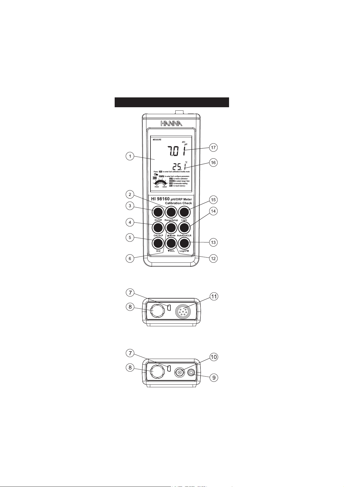
1) Liquid Crystal Display (LCD).
2) Range key, to select pH or mV range (HI 98150 & HI 98160
only).
Setup key, to enter/exit SETUP mode.
3) On/Off key, to turn the instrument ON and OFF.
4) CAL key, to enter/exit calibration mode.
GLP key, to display Good Laboratory Practice information.
5) 2nd key, to select second key function.
6) key, to manually increase temperature or other parameters.
Mode key, to select measurement resolution, 0.1 pH / 0.01 pH,
or to toggle between mV and Rel mV (HI 98150 & HI 98160
only).
7) USB connector.
8) Battery compartment cap.
9) Temperature probe socket (HI 98160).
10) BNC electrode connector (HI 98160).
11) DIN connector for SMART electrode (HI 98140 & HI 98150).
12) key, to manually decrease temperature or other parameters.
RCL key, to enter/exit view logged data mode.
13) Log key, to store measured data.
CFM key, to confirm calibration point, confirm delete record or
confirm different set values.
14) AutoEnd key, to freeze first stable reading on the LCD.
CLR key, to clear calibration or enter delete logged data screen.
15) Light key, to toggle display backlighting.
16) Secondary LCD.
17) Primary LCD.
6
Page 7
EGNAR
Hp0.02ot0.4–
Hp00.02ot00.4–
(Vm0002±;Vm9.996± 05189IH &
06189IH )
)Fº0.842ot0.4–(Cº0.021ot0.02–
NOITULOSER
Hp1.0
Hp10.0
()Vm9.996±(Vm1.0 05189IH & 06189IH )
()Vm0002±(Vm1 05189IH & 06189IH )
)Fº1.0(Cº1.0
YCARUCCA
Fº86/Cº02@
Hp1.0±
Hp10.0±
()Vm9.996±(Vm2.0± 05189IH & 06189IH )
()Vm0002±(Vm1± 05189IH & 06189IH )
rorreeborpgnidulcxe)Fº4.0±(Cº2.0±
egnartesffoVmleR (Vm0002± 05189IH & 06189IH )
noitarbilaCHp
(noitarbilactniop-eerhtotpU 04189IH )
(noitarbilactniop-evifotpU 05189IH & 06189IH ,)
rof8(7 06189IH elbaliavasreffubdradnats)
-00.3,86.1( 06189IH ,81.9,10.7,68.6,10.4,
,)54.21,10.01 sreffubmotsuc2dna
noitarbilaCVm
,0stniop3roVm053,0tastniop2,citamotuA
Vm0091,053
noitarbilaCtesffO Hp1±
noitarbilaCepolS %011ot08morF
noitasnepmoCerutarepmeT
morfcitamotuArolaunaM
)Fº0.842ot0.4–(Cº0.021ot0.02–
edortcelEHp
B0321IH rofdedulcni( 06189IH )
D8161IH rofdedulcni( 04189IH & 05189IH )
eborPerutarepmeT 2667IH rofdedulcni( 06189IH )
GOL selpmas005,dnamednO
ecnadepmItupnI 01
21
smho
efiL&epyTyrettaB
seirettabAAAV5.1x3
tuohtiwesusuounitnocfosruoh002.xorppa
)thgilkcabhtiwsruoh05(thgilkcab
ffo-otuA
rosetunim06,02,01,5:elbatcelesresU
delbasid
noitacinummoCCP BSUdetalosiotpO
snoisnemiD )”4.1x8.2x3.7(mm63x27x581
thgieW ).zo6.01(g003
tnemnorivnE
)Fº221–23(Cº05–0
%001HR.xam
ytnarraW sraey2
SPECIFICATIONSSPECIFICATIONS
SPECIFICATIONS
SPECIFICATIONSSPECIFICATIONS
7
Page 8

OPERATIONAL GUIDEOPERATIONAL GUIDE
OPERATIONAL GUIDE
OPERATIONAL GUIDEOPERATIONAL GUIDE
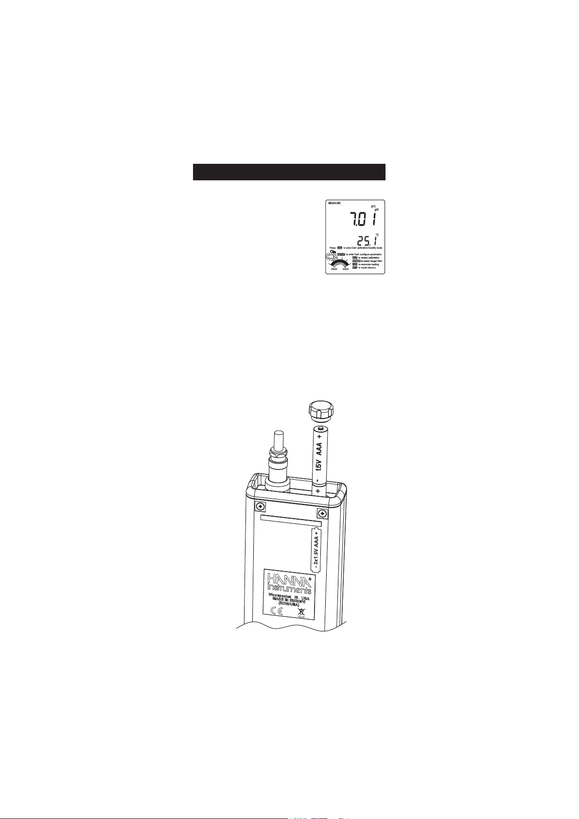
INITIAL PREPARATION
The instrument is supplied complete with batteries. For placing the
batteries inside the meter, see page 33.
To prepare the instrument for use, connect the pH electrode to the input
socket on the top of the instrument. For HI 98160 connect the temperature
probe to the temperature socket too. The temperature probe is used in
conjunction with the pH electrode for pH temperature compensation, but
it can also be used independently to take temperature measurements. If
the probe is disconnected, temperature can be set manually with the
ARROW keys (see page 9 for details).
Turn the instrument ON by pressing
On/Off.
At start-up the display will show all
the available segments for a few seconds
(or while the button is held), followed
by the percentage indication of the
remaining battery life. The meter is
now ready to operate.
After measurement switch the instrument off, remove the electrodes,
clean the electrode and store it with a few drops of HI 70300 storage
solution in the protection cap.
Note: In order to avoid error conditions when working with SMART
electrodes, be sure the electrode is connected before the instrument
is turned ON and is disconnected only after the instrument is
turned OFF.
The auto-off feature turns the instrument off after a set period (default
20 min) to save battery life. To set another period or to disable this
feature, see SETUP menu on page 21.
The auto-off backlight feature turns the backlight off after a set period
(default 1 min). To set another period or to disable this feature, see
SETUP menu on page 21.
pH MEASUREMENTS
To take a pH measurement remove the electrode
protective cap and simply submerse the tip of the
electrode (3cm/1¼”) and the temperature probe
(HI 98160 only) into the sample to be tested. If
necessary, press Range until the display changes to
the pH mode. Allow the electrode to equilibrate and
reading to stabilize (hourglass symbol will turn off).
8
3cm
(1¼”)
Page 9

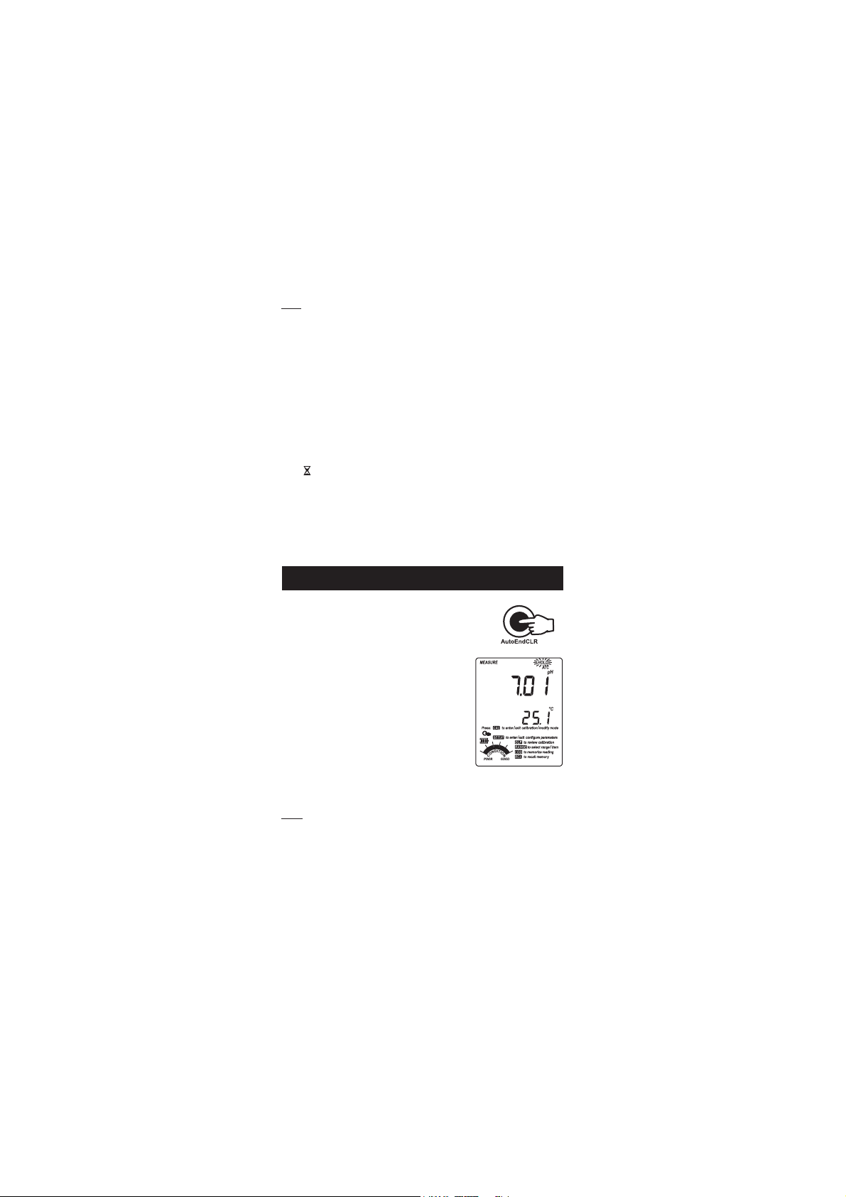
The LCD will show the pH measurement
together with the temperature of the
sample. In order to take more accurate
pH measurements, make sure that the
electrode and instrument is calibrated (see
page 11 for details).
Hanna recommends to keep the pH electrode wet and to rinse throughly
with the sample before measurements.
The pH reading is directly affected by temperature. In order for the
instrument to measure the pH accurately, temperature must be taken
into consideration. If the sample temperature is different from the
ambient temperature, allow a few minutes for the pH electrode to reach
thermal equilibrium.
The HI 1618D pH sensor contains an integral temperature sensor so the
pH reading is automatically temperature compensated (ATC) on the
HI 98140 and HI 98150. If the temperature is out of range (due to
temperature sensor failure) these instruments will enter MTC mode and
permit temperature values to be set manually using the ARROW keys.
To use the instrument's Automatic Temperature Compensation feature for
HI 98160, connect and submerse the temperature probe into the sample
as close to the electrode as possible and wait for a few seconds.
If manual temperature compensation (MTC) is desired, the
temperature probe must be disconnected from the instrument
(HI 98160 only).
The display will show the default temperature
of 25 ºC, the last measured temperature
reading, or the last set temperature, with
the “ºC” (or “ºF”) tag blinking.
The “MTC” tag and arrow symbols
light up on the LCD to indicate that the
instrument is in MTC mode and the arrow
keys can be used to enter the desired temperature value.
Note: When in MTC the user can press and hold the ARROW keys to
set the measurement temperature. The instrument will start
incrementing/decrementing the temperature value. The instrument
keeps measuring using the MTC value for temperature compensated
pH and the display is updated.
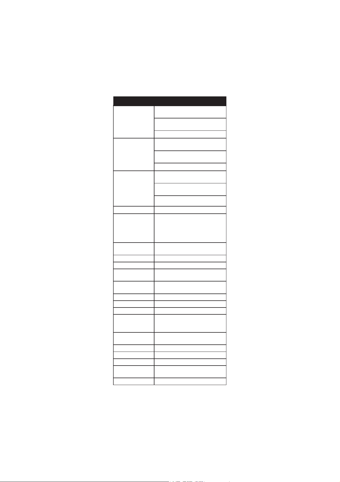
ORP MEASUREMENTS (HI 98150 & HI 98160 only)
To perform ORP measurements, connect an optional
ORP electrode (see Accessories section) to the instrument
and turn it ON. If necessary, enter the mV mode by
pressing Range until the display changes to mV.
3cm
(1¼”)
9
Page 10
Submerse the ORP electrode tip (3cm/1¼”)
into the sample to be tested and wait a few
seconds for the reading to stabilize.
Measurements within the ±699.9 mV range
are displayed with 0.1 mV resolution, while
outside this range the resolution automatically
switches to 1 mV.
The “ATC” (or “MTC”) tag is turned off because ORP measurements are
not temperature compensated.
For accurate ORP measurements, the surface of the electrode must be
clean and smooth. Pretreatment solutions are available to condition the
electrode and improve its response time (see Accessories section, page 41).
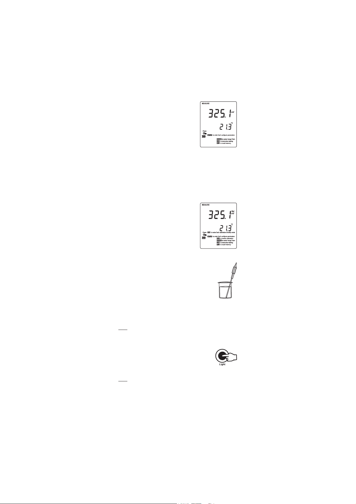
RELATIVE mV MEASUREMENTS (HI 98150 & HI 98160 only)
To enter Relative mV mode, press 2nd then
Mode while in mV measurement mode. The
relative mV reading will be displayed on the
primary LCD and the current temperature
value on the secondary LCD.
Relative mV is an operation mode in which the
displayed electrode potential (mV) can be
changed by means of a calibration control
offset. See page 17.
TEMPERATURE MEASUREMENTS
The pH electrodes used for HI 98140 and HI 98150 also
include an integral temperature measuring element.
For HI 98160 connect the HI 7662 temperature probe to
the appropriate socket, submerse the temperature probe
into the sample and permit it to equilibrate by watching
the reading on the secondary LCD.
If the temperature is out of range, or the temperature probe is not
connected (HI 98160 only) the instruments will display the last in
range temperature reading and enter MTC mode (see page 9).
Note: The temperature can be displayed in Celsius degrees (ºC) or in
Fahrenheit degrees (ºF) (see SETUP for details, page 21).
BACKLIGHT FEATURE
The instrument is provided with a Backlight feature to
enhance display readability in low light conditions. It
can be easily toggled on and off through the keypad by
pressing Light.
Note: The backlight automatically shuts off after a set time period to
save battery life (see SETUP for details, page 21).
If battery percentage is less than 20% the backlight can not be ON.
10
Page 11

pp
H CALIBRATIONH CALIBRATION
p
H CALIBRATION
pp
H CALIBRATIONH CALIBRATION
Hanna recommends frequent calibrations, especially if high accuracy is
required.
The pH range should be recalibrated:
• Whenever the pH electrode is replaced.
• At least once a week, but daily is recommended.
• After testing aggressive chemicals.
• After electrode is cleaned.
• When calibration alarm time out is expired - “Cal Due” tag blinks (if
feature is enabled).
• If “Outside Cal Range” message blinks during pH measurement
(the measurement range is not covered by current calibration).
PROCEDURE
The instrument offers a choice of 7 buffers that are automatically recognized
(1.68, 4.01, 6.86, 7.01, 9.18, 10.01 and 12.45 pH) and also allows
the user to enter two more pH values for calibration, “Custom 1” and
“Custom 2”. The set custom buffers are the buffer values at 25 ºC.
HI 98160 offers also 3.00 pH buffer choice for wine measurement.
When a custom buffer is selected during calibration, the “Custom” tag
is displayed on the LCD and its value can be changed in a ±1.0 pH
window, around the set value, in accordance with current temperature.
For accurate pH measurements, it is recommended to perform a five-point
(HI 98150 & HI 98160) calibration respectevely a three-point (HI 98140)
calibration. However, at least a two-point calibration is suggested.
The instrument will automatically skip the buffers used during calibration
and the buffers which are in a ±0.2 pH window, around one of the
calibrated buffers.
• Pour small quantities of selected buffer solutions into clean beakers.
For accurate calibration use two beakers for each buffer solution, the
first one for rinsing the electrode and the second one for calibration.
• Remove the protective cap and rinse the electrode with some of the
buffer solution to be used for the first calibration point.
FIVE-POINT CALIBRATION (HI 98150 & HI 98160)
• Submerse the pH electrode and the temperature
probe approximately 3 cm (1¼”) into a buffer
solution of your choice (pH 1.68, 4.01, 6.86,
7.01, 9.18, 10.01, 12.45 or a custom
buffer) and stir gently. The temperature
probe should be close to the pH electrode.
• Press CAL. The instrument will display the
measured pH on the primary LCD and “7.01”
buffer on the secondary LCD, together with
“CAL” and “Cal Point 1” tags.
3cm
(1¼”)
11
Page 12

• If necessary, press the ARROW keys to select a different buffer value.
• The “ ” tag will blink on the LCD until the reading is stable.
• When the reading is stable and close to the selected buffer, “CFM”
tag blinks.
• Press CFM to confirm calibration.
• The calibrated value is then displayed on
the primary LCD and the secondary LCD
will display the second expected buffer
value, together with “CAL” and “Cal
Point 2” tags.
• After the first calibration point is confirmed,
submerse the pH electrode and the temperature
probe (if required) approximately 3 cm (1¼”) into the second buffer solution
and stir gently. The temperature probe should be close to the pH electrode.
• If necessary, press the ARROW keys to select the appropriate buffer value.
• The “ ” tag will blink on the LCD until the reading is stable.
• When the reading is stable and close to the selected buffer, “CFM”
tag blinks.
• Press CFM to confirm calibration.
• The calibrated value is then displayed on the primary LCD and the
secondary LCD will display the third expected buffer value.
• After the second calibration point is confirmed, submerse the pH
electrode and the temperature probe approximately 3 cm (1¼”) into
the third buffer solution and stir gently. The temperature probe
should be close to the pH electrode.
• If necessary, press the ARROW keys to select a different buffer value.
• The “ ” tag will blink on the LCD until the reading is stable.
• When the reading is stable and close to the selected buffer, “CFM”
tag blinks.
• Press CFM to confirm calibration.
• The calibrated value is then displayed on the primary LCD and the
secondary LCD will display the fourth expected buffer value.
• After the third calibration point is confirmed, submerse the pH
electrode and the temperature probe approximately 3 cm (1¼”) into
the fourth buffer solution and stir gently. The temperature probe
should be close to the pH electrode.
• If necessary, press the ARROW keys to select a different buffer value.
• The “ ” tag will blink on the LCD until the reading is stable.
• When the reading is stable and close to the selected buffer, “CFM”
tag blinks.
• Press CFM to confirm calibration.
12
Page 13

• The calibrated value is then displayed on the primary LCD and the
secondary LCD will display the fifth expected buffer value.
• After the fourth calibration point is confirmed, submerse the pH
electrode and the temperature probe approximately 3 cm (1¼”) into
the fifth buffer solution and stir gently. The temperature probe
should be close to the pH electrode.
• If necessary, press the ARROW keys to select a different buffer value.
• The “ ” tag will blink on the LCD until the reading is stable.
• When the reading is stable and close to the selected buffer, “CFM”
tag blinks.
• Press CFM to confirm calibration.
• The instrument stores the calibration values and
returns to normal measurement mode.
Note: For HI 98140 calibration proceed as in the FIVE-POINT CALIBRATION
above. After the third point is confirmed the instrument stores the
calibration value and returns to measurement mode.
FOUR, THREE or TWO-POINT CALIBRATION
• Proceed as described in FIVE-POINT CALIBRATION section.
• Press CAL after the appropriate accepted calibration
point. The instruments will return to measurement
mode and will memorize the calibration data.
ONE-POINT CALIBRATION
Two SETUP selectable options are available for one-point calibration:
“Pnt” and “OFFS”. See page 22 for Setup information using “1Pnt”
parameter.
If the “Pnt” option is selected, the adjacent slopes will be recalculated
using the new calibration value.
If the “OFFS” option is selected, an electrode offset correction is performed
keeping the existing slopes unchanged, but offsetting all by same value.
• Proceed as described in FIVE-POINT CALIBRATION section.
• Press CAL after the first calibration point was confirmed. The
instruments will memorize the one-point calibration
data and will return to measurement mode.
Notes: • Press Range to toggle between pH buffer
and temperature reading during calibration.
• If the value measured by the instrument is not close to the
selected buffer, “WRONG” “ ” and “WRONG” “ ” tags
will blink alternately. In this case check if the correct buffer
has been selected or used, or regenerate the electrode by
following the Cleaning Procedure (see page 39). If necessary,
change the buffer or the electrode.
• If the buffer temperature or the manual temperature exceeds
the temperature limits of the buffer, “WRONG” “ ” tags
and temperature reading will blink.
13
Page 14
• If “WRONG” tag and “OLd” message are displayed on
the secondary LCD, an inconsistency exists between new
and previous (old) calibration data. Clear old calibration
parameters and proceed with calibration from the current
calibration point. The instrument will keep all confirmed
values during current calibration.
• With one-point calibration there is no “Condition” and only
the frame is shown. Calibration time out is active.
• Each time a buffer is confirmed, the new calibration
parameters replace the old calibration parameters of
the corresponding buffer.
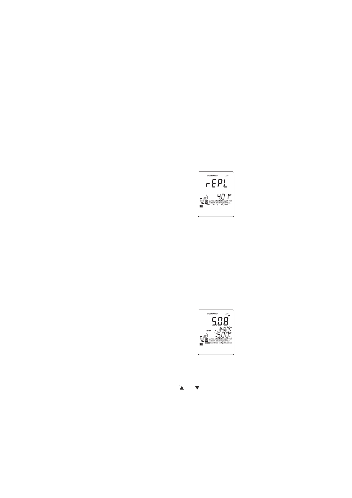
If current confirmed buffer has no
correspondence in the existing stored
calibration and this is not full, the
current buffer is added to the existing
stored calibration.
If the existing stored calibration is
full (five calibration points), after confirming the last
calibration point, the instrument will ask which buffer will be
replaced by current buffer.
Press the ARROW keys to select another buffer to be replaced.
Press CFM to confirm the buffer that will be replaced.
Press CAL to exit this function. In this case, the buffer
calibration will not be stored.
Note: The replaced buffer is not removed from the calibration list and
can be selected for the next calibration.
WORKING WITH CUSTOM BUFFERS
If a custom buffer was configured in SETUP menu, it can be selected for
calibration by pressing the ARROW keys. The “CUSTOM” tag will be
displayed blinking on the LCD.
Press 2nd then Setup if you want to adjust
the buffer value to it’s value at the current
temperature. The buffer value, displayed on
the secondary LCD, will start blinking.
Use the ARROW keys to change the buffer value.
After about 5 seconds, the last buffer change
will be updated. Press 2nd then Setup if you want to change it again.
Notes: • Custom buffer value can be adjusted in a ±1.00 pH window,
around the set value.
• If you want to return to the set custom buffer value, simply
press the ARROW keys ( then ) to select again the
custom buffer.
14
Page 15
CLEAR CALIBRATION
To clear calibration press 2nd then CLR or CLR alone
after entering CAL mode. The “CLr ALL” message will
be displayed on the LCD along with “Cal Due” CLR
message blinking.
All old calibrations, starting with current selected buffer are cleared and
the instrument continues calibration.
Note: If CLR is pressed during the first calibration point, the instrument
returns to measurement mode.
CONDITION
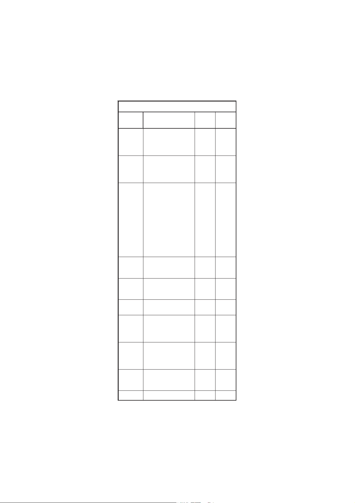
The display is provided with a 5-dot bargraph (unless the feature is
disabled) which gives an indication of the electrode status after
calibration as follows:
Bargraph indication Condition value
All 5 dots steady 81 to 100% of life
4 dots steady 61 to 80%
3 dots steady 41 to 60%
2 dots steady 21 to 40%
1 dot steady 1 to 20%
1 dot blinking 0%
Only frame is ON No info available
The “condition” bargraph remains active until the end of the calibration day.
Note: The electrode condition is evaluated only if current calibration
includes at least two standard buffers.
CLEAN ELECTRODE
Each time pH calibration is performed, the instrument internally compares
the new calibration with the one previously stored.
When this comparison indicates a significant difference, the “CLEAN” “ ”
tags blink on the LCD to advise the user that the pH electrode may need
to be cleaned (see ELECTRODE CONDITIONING & MAINTENANCE section
for details, page 37).
After cleaning, perform a new calibration.
Note: If calibration data are cleared, the comparison is done with the
default values.
15
Page 16

PMET SREFFUBHp
Cº Fº 86.1 10.4 68.6 10.7 81.9 10.01 54.21
0 23 76.1 10.4 89.6 31.7 64.9 23.01 83.31
5 14 76.1 00.4 59.6 01.7 93.9 42.01 81.31
01 05 76.1 00.4 29.6 70.7 33.9 81.01 99.21
51 95 76.1 00.4 09.6 50.7 72.9 21.01 08.21
02 86 86.1 00.4 88.6 30.7 22.9 60.01 26.21
52 77 86.1 10.4 68.6 10.7 81.9 10.01 54.21
03 68 86.1 20.4 58.6 00.7 41.9 69.9 92.21
53 59 96.1 30.4 48.6 99.6 11.9 29.9 31.21
04 401 96.1 40.4 48.6 89.6 70.9 88.9 89.11
54 311 07.1 50.4 38.6 89.6 40.9 58.9 38.11
05 221 17.1 60.4 38.6 89.6 10.9 28.9 07.11
55 131 27.1 80.4 48.6 89.6 99.8 97.9 75.11
06 041 27.1 90.4 48.6 89.6 79.8 77.9 44.11
56 941 37.1 11.4 48.6 99.6 59.8 67.9 23.11
07 851 47.1 21.4 58.6 99.6 39.8 57.9 12.11
57 761 67.1 41.4 68.6 00.7 19.8 47.9 01.11
08 671 77.1 61.4 78.6 10.7 98.8 47.9 00.11
58 581 87.1 71.4 78.6 20.7 78.8 47.9 19.01
09 491 97.1 91.4 88.6 30.7 58.8 57.9 28.01
59 302 18.1 02.4 98.6 40.7 38.8 67.9 37.01
pp
H BUFFER TEMPERATUREH BUFFER TEMPERATURE
p
H BUFFER TEMPERATURE
pp
H BUFFER TEMPERATUREH BUFFER TEMPERATURE
DEPENDENCEDEPENDENCE
DEPENDENCE
DEPENDENCEDEPENDENCE
The temperature has an effect on pH. The calibration buffer solutions are
affected by temperature changes to a lesser degree than normal
solutions. During calibration the instrument will automatically calibrate
to the pH value corresponding to the measured or set temperature.
During calibration the instrument will display the pH buffer value at 25 ºC.
16
Page 17

However, temperature correction during pH measurements provides
values at the temperature of measurement. Actual pH values may differ
if measured at two different temperatures.
RELATIVE RELATIVE
RELATIVE
RELATIVE RELATIVE
(HI 981(HI 981
(HI 981
(HI 981(HI 981
To enter Rel mV operation press 2nd and Mode from mV measurement.
• Place the ORP electrode into solution or
standard.
• Wait for a stable mV to be displayed.
• Press CAL when the instrument is in
RELATIVE mV measurement mode. The
relative mV value is displayed on the
primary LCD and the absolute mV value
on the secondary LCD.
• Use the ARROW keys to change the displayed relative mV value.
• When the reading is stable, in mV range and the Relative mV offset
is inside the offset window (±2000 mV), “CFM” tag blinks.
• Press CFM to confirm the relative mV calibration. The instrument will
return to measurement mode.
• If the absolute mV reading is out of range or the Relative mV offset
is out of the offset window, “WRONG” tag will blink. Verify sensor tip
is fully submersed in solution and electrode is fully plugged in.
mm
V CALIBRATIONV CALIBRATION
m
V CALIBRATION
mm
V CALIBRATIONV CALIBRATION
5050
& HI 981 & HI 981
50
& HI 981
5050
& HI 981 & HI 981
6060
60
6060
))
)
))
17
Page 18

GOOD LABORATORY PRACTICE (GLP)GOOD LABORATORY PRACTICE (GLP)
GOOD LABORATORY PRACTICE (GLP)
GOOD LABORATORY PRACTICE (GLP)GOOD LABORATORY PRACTICE (GLP)
GLP is a set of functions that allows storage and retrieval of data
regarding the maintenance and status of the electrode.
All data regarding pH or Rel mV calibration is stored for the user to
review when necessary.
HI 98140 and HI 98150 use electrodes with built-in EEPROM in which
calibration data is read at start up and stored after calibration. The
meter can automatically analyze the data and advise the user during
measurements if a problem is found with a clear message.
If the calibration offset is outside ±30 mV window, “OLD Probe” tag is
displayed blinking to warn user to perform a cleaning procedure.
If the calibration offset is outside ±60 mV window “DEAD Probe” tag
is displayed blinking to warn the user that readings are not reliable.
EXPIRED CALIBRATION
The instrument is provided with a real time clock (RTC), to monitor the
time elapsed since the last pH calibration.
The real time clock is reset every time the instrument is calibrated and the
“expired calibration” status is triggered when the instrument detects a
calibration time out. The “Cal Due” tag will start blinking to warn the
user that the instrument should be recalibrated.
The calibration time out can be set (see SETUP for details, page 21) from
OFF (function disabled) to 7 days.
For example, if a 4 days time out has been selected, the instrument will
issue the alarm exactly 4 days after the last calibration.
However, if at any moment the expiration value is changed (e.g. to
5 days), then the alarm will be immediately recalculated and appear
5 days after the last calibration.
Notes: • When the instrument is not calibrated or calibration is cleared
(default values loaded) there is no “expired calibration”,
and the display always shows the “Cal Due” tag blinking.
• When an abnormal condition in the RTC is detected, the
instrument forces the “expired calibration” status.
LAST pH CALIBRATION DATA
The last pH calibration data is stored automatically
after a successful calibration.
To view the pH calibration data, press 2nd then
GLP when the instrument is in pH measurement
mode.
The instrument will display the date (mm.dd)
and the time (hh:mm) of the last calibration.
The “condition” bargraph remains active until the end of the calibration day.
18
Page 19

Press the ARROW keys to view the next
calibration parameter (pressing the key):
• The pH calibration slope and offset.
The GLP slope is the average of the calibration slopes; the percentage is
referred to the ideal slope value. For example 59.16 mV/pH at 25 °C.
• The calibration buffers in calibrating order,
for the last calibration.
The first pH calibration buffer:
The second pH calibration buffer (if exist):
The third pH calibration buffer (if exist):
The fourth pH calibration buffer (if exist):
The fifth pH calibration buffer (if exist):
19
Page 20

Notes: • The “OLd” message displayed beside the pH value means
that this buffer was not used during last calibration. Press
2nd then Setup if you want to see calibration date (or time,
if old calibration was performed in the same day with current
calibration). In this case, the calibration buffer number is not
displayed on the LCD.
• If “not CAL” message appears on the LCD, the instrument
informs you that calibration was performed in less than five
points.
• The Calibration Alarm Time Out status.
If disabled,
or the number of days until the calibration
alarm will be displayed (e.g. 5 days), or
from the time calibration expired (e.g.
–3 days).
• The instrument ID.
LAST RELATIVE mV CALIBRATION DATA
Last Relative mV calibration data is stored automatically after a successful
calibration.
To view the Relative mV calibration data, press 2nd then GLP while in
Relative mV measurement mode.
The instrument will display the Relative mV GLP information.
• The date (mm.dd) and the time (hh:mm:ss) of the last Rel mV
calibration as in pH GLP mode.
Press the ARROW keys to view the next calibration parameter (pressing
the key):
• The Relative mV calibration offset as in pH GLP mode. For the slope
position “----” is displayed.
• The instrument ID as in pH GLP mode.
Notes: • Press 2nd then GLP or only GLP at any moment and the
instrument will return to measurement mode.
• If calibration has not been performed, the instrument displays
“no CAL” message blinking.
• Press 2nd and Setup while date and time are displayed in
order to view the year in the first LCD line.
20
Page 21

SETUPSETUP
SETUP
SETUPSETUP
Setup mode allows viewing and configuring the following parameters:
• Calibration Alarm Time Out (pH range only)(dAY)
• Custom buffers (1 or 2) (pH range only) (Custom)
• One-point calibration behavior (pH range only) (1Pnt)
• Current Time (hour & minute)
• Current Date (month, day & year)
• Beep Status (bEEP)
• Instrument ID (InSld)
• Auto-off backlight timer (LIGH)
• Auto power off timer (AOFF)
• Temperature Unit
To enter SETUP mode, press Setup button directly on the HI 98140 and
2nd then Setup on the HI 98150 & HI 98160 while the instrument is
in measurement mode.
Select the desired setup parameter using the
ARROW
keys.
Press CAL if you want to change the item
value. “CFM” tag and the selected item (e.g.
hour, in setting up the correct time) will start
blinking.
Press the ARROW
If there is another item to be set (e.g. minutes), press Range (HI 98150
& HI 98160), 2nd then Mode (HI 98140). The other item will start
blinking.
Press the ARROW
displayed value.
Press CFM to confirm or CAL to escape
without changing.
Press the ARROW
previous parameter.
Press Setup to exit SETUP menu at any time.
keys to change the displayed value.
keys to change the
keys to select the next/
The following table (see page 22) lists the SETUP parameters, their valid
values range and the factory settings (default). Use to move through
parameters in this order.
21
Page 22
SRETEMARAPPUTES
noitaiverbbA seodtitahW
dilaV
seulaV
tluafeD
YAd
lavretnitesotretemarapsihtesU
aerofebsnoitarbilacneewteb
siegassemeudnoitarbilac
.deyalpsid
ot1roFFO
syad7
FFO
motsuC
reffubmotsuc2otpuehtretnE
stimreP.retemarapsihtniseulav
ebot"snoitulosresu"owt
.noitarbilacreffubrofelbatceles
00.4-roon
Hp00.02ot
on
tnP1
ebnacnoitarbilactniop-enoA
.noitarbilacreffub5-2aretfadesu
ehttsujdalliwtniop-enoehT
.syaw2foenonoitarbilacsuoiverp
aecalperroddalliw"tnP"
owtneewtebtniopnoitarbilac
weN.sreffubdetarbilacylsuoiverp
detaulaveeblliwseulavepols
"SFFO".eulavsihtnopudesab
dnasnoitarbilacllasalblliw
tnatsnocaybstnemerusaem
.eulav
rotnP
SFFO
tnP
emiT
ecnereferotdesusieulavsihT
agnisugniggoldnasnoitarbilac
)mm:hh(.kcolcruoh42
ot00:00
95:32
00:0
etaD
ecnereferotdesusieulavsihT
.gniggoldnasnoitarbilac
)yyyy.dd.mm(
0002.10.10
ot
9902.13.21
9002.10.10
PEEb
srorrelangisotdesuenotpeeB
.egnahcgnimrifnocdna
ffO/nO FFO
dISnI
sihteviG:DItnemurtsnI
nehW.#teercsidatnemurtsni
tnemurtsnisihtsgolgnidaolnwod
.deifitnedieblliw
ot0000
9999
0
HGIL
sithgilkcabfI.remitthgilkcaB
ebottistimrep,yalpsidnodenrut
evasotffodenrutyllacitamotua
.rewopyrettab
ro5,1,ffO
setunim01
etunim1
FFOA
nrutottinustimreP:remitffootuA
yrettabevasotemitteserpretfaffo
.rewop
,01,5,ffO
06ro02
setunim
setunim02
.deyalpsidtinuerutarepmeT F°roC° C°
22
Page 23
Note: The custom buffers can be set only with 0.01 pH resolution, at
25 ºC. Press Range (HI 98150 & HI 98160) or 2nd and Mode
(HI 98140) repeatedly while in custom buffer setting mode until
the closest buffer value to the desired custom buffer to be set is
displayed on the LCD. If selecting “no” option, the selected custom
buffer is removed. After removing one custom buffer, the custom
buffer list is reordered.
LOGGINGLOGGING
LOGGING
LOGGINGLOGGING
This feature allows the user to log pH or Rel mV measurements, together
with corresponding mV and temperature automatically. All logged data
can be transferred to a PC through the USB port.
The maximum logging space is 500 record locations.
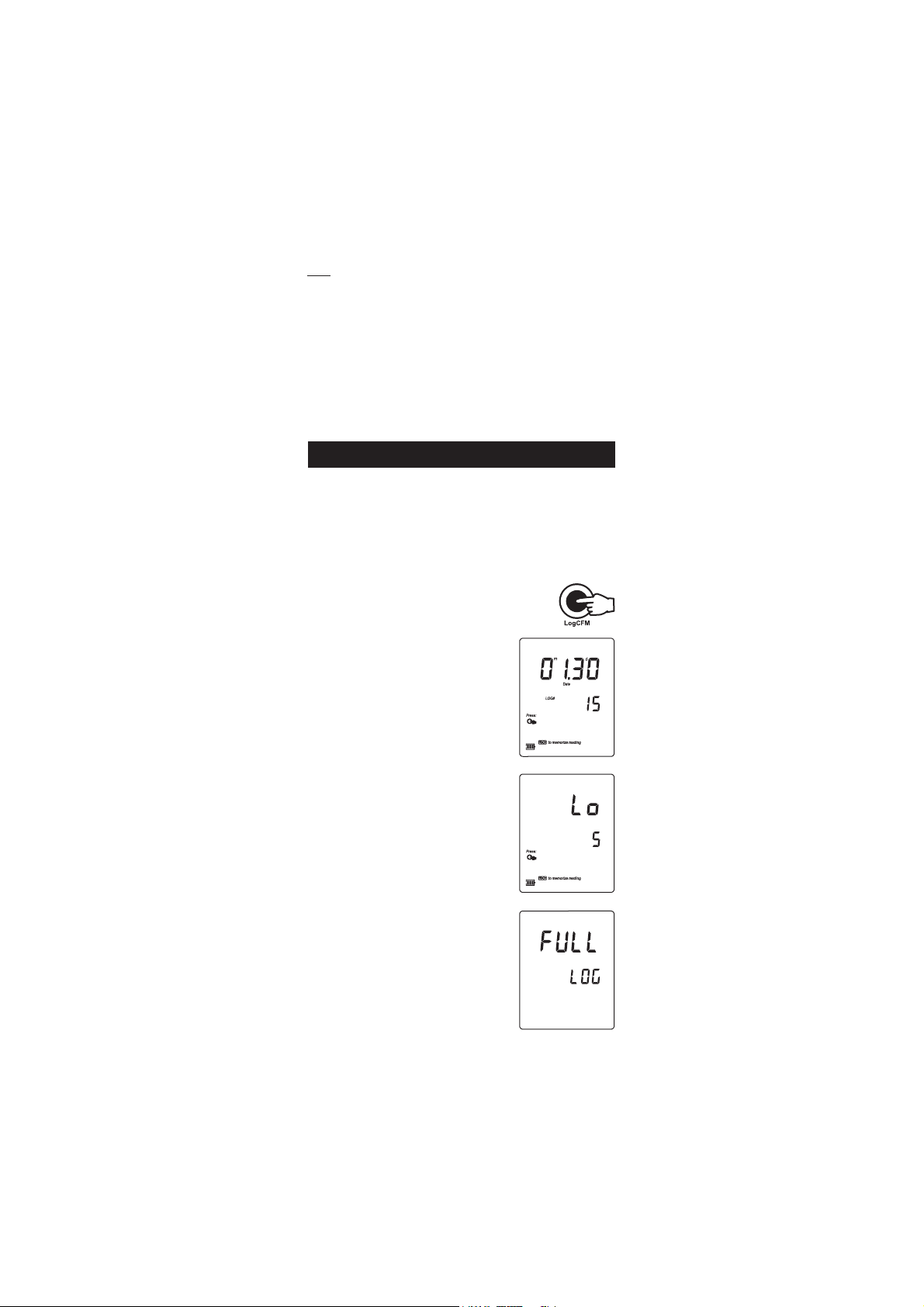
LOGGING THE CURRENT DATA
To store the current reading into memory, press
Log while in measurement mode.
The instrument will display the current date
(mm.dd) on the primary LCD, the record number
on the secondary LCD and then the available
number of logs remaining.
If there are less than 6 memory locations
remaining, the “Lo” message will be displayed
for a few seconds to alert the user, and then
the available number of remaining logs is
displayed on the LCD.
If the LOG space is full, “FULL LOG” message
will be displayed on the LCD for a few seconds
and then ”FrEE 0” message.
The instrument returns to normal measurement
mode.
23
Page 24

VIEW LOGGED DATA
Press 2nd then RCL to retrieve the information
stored while in measurement mode for the
specific range. “RECALL MEMORY” will be
displayed on LCD.
If no records were logged, the instrument will
display “no rEC” message blinking.
Otherwise, the instrument will display the
logged data, in according with the selected
range:
• If RCL mode was entered while the instrument
was in pH range: the last pH memorized
reading appears on the primary LCD and
the record number on the secondary LCD.
• If RCL mode was entered while the instrument
was in mV or Rel mV range: the last Rel
mV memorized reading appears on the
primary LCD and the record number on
the secondary LCD.
Press Range (HI 98150 & HI 98160) or 2nd then Mode (HI 98140)
and the instrument will display the next logged parameter as shown
in the table below:
Parameter Primary LCD Secondary LCD
mV mV reading Temperature
DATE/TIME Month & day Hour & minutes
SLOPE Slope value in % Offset value in mV
Note: If in Rel mV RECALL mode regarding the slope, the instrument will
display “----” message on the primary LCD.
Press 2nd and CLR or simply CLR to delete records.
The “dEL” message is displayed on the primary LCD, the record number on
the secondary LCD and “CFM” tags will blink.
24
Page 25
• Press the ARROW keys to change the record number.
• Press CAL or Range or CLR to escape from DEL screen and enter view
record items mode.
Note: Pressing 2nd then Setup the instrument toggles between record
number and all records.
• Press 2nd then CFM or CFM to confirm delete. The “nuLL” message
will be displayed on the primary LCD for the selected record. While
“nuLL” message is displayed the 2nd, CAL, Range and CLR keys
are inactive. Press the ARROW keys to select an undeleted record.
• If “dEL ALL” option was selected, all logged data are deleted and
the instrument returns to measurement mode
Press 2nd then RCL at any time to return to measurement mode.
The “ ” and “WAIT” tags blinks during memory is reorganized.
AA
utoEndutoEnd
A
utoEnd
AA
utoEndutoEnd
To freeze the first stable reading on the LCD
press AutoEnd while the instrument is in
measurement mode.
The ”HOLD” tag will be displayed blinking on
the LCD until the reading will stabilize.
When the reading is stable, the “HOLD” tag
stops blinking and the reading is frozen on the
LCD.
Press AutoEnd again to return to normal measurement mode.
Note: • Pressing Range (HI 98150 & HI 98160 only) the instrument
will display alternate measurement range, without leaving
AutoEnd mode. The Log key also holds AutoEnd mode.
• Pressing 2nd then Setup, GLP or RCL, the instrument
leaves AutoEnd mode and performs the selected function.
25
Page 26

TEMPERATURE CALIBRATIONTEMPERATURE CALIBRATION
TEMPERATURE CALIBRATION
TEMPERATURE CALIBRATIONTEMPERATURE CALIBRATION
(for technical personnel only)
All the instruments are factory calibrated for temperature.
Hanna’s temperature probes are interchangeable and no temperature
calibration is needed when they are replaced.
If the temperature measurements are inaccurate, temperature recalibration
should be performed.
For an accurate recalibration, contact your dealer or the nearest Hanna
Customer Service Center, or follow the instructions below.
• Prepare a vessel containing ice and water and another one containing
hot water (at approximately 50 ºC or 122 ºF). Place insulation
material around the vessels to minimize temperature changes.
• Use a calibrated thermometer with a resolution of 0.1 ºC as a
reference thermometer. Connect the HI 7662 temperature probe to
the appropriate socket (HI 98160) or the pH probe (HI 98140 &
HI 98150).
• With the instrument off, press and hold down the Range & keys,
then power on the instrument. The “CAL” tag will appear and the
secondary LCD will show “0.0 ºC”. The primary LCD will display the
measured temperature or the ”----” message, if the measured
temperature is out of range.
• Submerse the temperature probe into the vessel with ice and water
as close as possible to the reference thermometer. Allow a few seconds
for the probe to stabilize.
• Use the ARROW keys to set the reading on the secondary LCD to that
of ice and water, measured by the reference thermometer. When the
reading is stable and close to the selected calibration point, “CFM”
tag will blink.
• Press CFM to confirm. The secondary LCD will
display “50.0 ºC”.
• Submerse the temperature probe into the second vessel as close as
possible to the reference thermometer. Allow a few seconds for the
probe to stabilize.
• Use the ARROW keys to set the reading on the secondary LCD to that
of the hot water.
• When the reading is stable and close to the selected calibration
point, “CFM” tag will blink.
26
Page 27

• Press CFM to confirm. The instrument returns
to measurement mode.
Note: If the reading is not close to the selected calibration point, “WRONG”
tag will blink. Change the temperature probe and restart
calibration.
mm
V CALIBRATION V CALIBRATION
m
V CALIBRATION (HI 98160 only)
mm
V CALIBRATION V CALIBRATION
(for technical personnel only)
All the instruments are factory calibrated for mV.
Hanna’s ORP electrodes are interchangeable and no mV calibration is
needed when they are replaced.
If the mV measurements are inaccurate, mV recalibration should be
performed.
For an accurate recalibration, contact your dealer or the nearest Hanna
Customer Service Center, or follow the instructions below.
A two-point calibration can be performed at 0 mV and 1800 mV.
• Attach to the BNC connector a mV simulator with an accuracy of
±0.1 mV.
• With the instrument off, press and hold down the Light & Log keys,
then power on the instrument. The “CAL” tag will appear and the
secondary LCD will show “0.0 mV”.
• Set 0.0 mV on the simulator.
When the reading is stable and close to the selected calibration
point, “CFM” tag will blink.
• Press CFM to confirm. The secondary LCD will display “1800 mV”.
• Set 1800.0 mV on the simulator.
When the reading is stable and close to the selected calibration
point, “CFM” tag will blink.
• Press CFM to confirm. The instrument returns to measurement
mode.
Notes: • If the reading is not close to the selected calibration point,
“WRONG” tag will blink. Verify calibration condition or
contact your vendor if you can not calibrate.
• Press CAL in any moment of the calibration process. The
instrument will return to measurement mode.
27
Page 28

PC INTERFACEPC INTERFACE
PC INTERFACE
PC INTERFACEPC INTERFACE
Data transmission from the instrument to the PC can be done with the
HI 92000 Windows® compatible software (optional). HI 92000 also
offers graphing and an on-line help feature.
Data can be exported to the most popular spreadsheet programs for
further analysis.
To connect your instrument to a PC, use a standard USB cable. Make
sure that your instrument is switched off and plug one connector to the
instrument’s USB socket and the other to the USB port of your PC.
Note: If you are not using Hanna Instruments HI 92000 software,
please see the following instructions.
In order to avoid data errors the serial communication interface is not
available if the battery percentage is less than 30%. The instrument will
answer with “Err9” message.
SENDING COMMANDS FROM PC
It is also possible to remotely control the instrument with any terminal
program. Use a standard USB cable to connect the instrument to a PC,
start the terminal program and set the communication options as follows:
8, N, 1, no flow control, baud rate 9600.
COMMAND TYPES
To send a command to the instrument follow the next scheme:
<command prefix> <command> <CR>
where: <command prefix> is 16 ASCII character.
<command> is the command code.
Note: Either small or capital letters can be used.
SIMPLE COMMANDS
RNG Is equivalent to pressing RANGE
MOD Is equivalent to pressing MODE
CAL Is equivalent to pressing CAL
CFM Is equivalent to pressing CFM
UPC Is equivalent to pressing the UP arrow key
DWC Is equivalent to pressing the DOWN arrow key
LOG Is equivalent to pressing LOG
RCL Is equivalent to pressing RCL
SET Is equivalent to pressing SETUP
CLR Is equivalent to pressing CLR
OFF Is equivalent to pressing OFF
AED Is equivalent to pressing AutoEnd
28
Page 29

CHR xx Change the instrument range according with the parameter
value (xx):
• xx=01 pH range/0.01 resolution
• xx=02 pH range/0.1 resolution
• xx=03 mV range
• xx=04 Relative mV range
The instrument will answer for these commands with:
<STX> <answer> <ETX>
where: <STX> is 02 ASCII code character (start of text)
<ETX> is 03 ASCII code character (end of text)
<answer>:
<ACK> is 06 ASCII code character (recognized command)
<NAK> is 21 ASCII code character (unrecognized command)
<CAN> is 24 ASCII code character (corrupted command)
COMMANDS REQUIRING AN ANSWER
The instrument will answer for these commands with:
<STX> <answer> <checksum> <ETX>
where the checksum is the bytes sum of the answer string sent as 2 ASCII
characters.
All the answer messages are with ASCII characters.
RAS Causes the instrument to send a complete set of readings in
according with the current range:
• pH and temperature reading (HI 98140), and mV
reading (HI 98150 & HI 98160) on pH range.
• Rel mV, absolute mV and temperature reading on
Rel mV range (HI 98150 & HI 98160).
The answer string contains:
• Meter mode (2 chars):
• 01 - pH range (0.01 resolution)
• 02 - pH range (0.1 resolution)
• 03 - mV range
• 04 - Rel mV range
• Meter status (2 chars of status byte): represents a 8
bit hexadecimal encoding.
• 0x10 - temperature probe is connected
• 0x01 - new GLP data available
• 0x02 - new SETUP parameter
29
Page 30

• Reading status (2 chars): R - in range, O - over
range, U - under range. First character corresponds
to the appropriate range reading. Second character
corresponds to mV reading.
• Primary reading (corresponding to the selected range)
- 7 ASCII chars, including sign and decimal point.
• Secondary reading (only when primary reading is
not mV) - 7 ASCII chars, including sign and decimal
point.
• Temperature reading - 7 ASCII chars, with sign and
two decimal points, always in ºC.
MDR Requests the instrument model name and firmware code
(16 ASCII chars).
GLP Requests the calibration data record.
The answer string contains:
• GLP status (1 char): represents a 4 bit hexadecimal
encoding.
• 0x01 - pH calibration available
• 0x02 - Rel mV calibration available
• 0x04 - ISE calibration available
• pH calibration data (if available), which contains:
• the number of calibrated buffers (1 char)
• the offset, with sign and decimal point (7 chars)
• the average of slopes, with sign and decimal
point (7 chars)
• the calibration time, yymmddhhmmss (12 chars)
• buffers information (for each buffer)
• type (1 char): 0 - standard, 1 - custom
• status (1 char): N (new) - calibrated in last
calibration; O (old) - from an old calibration.
• warnings during calibration (2 chars): 00 no warning, 04 - Clean Electrode warning.
• buffer value, with sign and decimal point
(7 chars).
• calibration time, yymmddhhmmss (12 chars).
• electrode condition, with sign (3 chars). The “-01”
code means not calculated.
30
Page 31

• Rel mV calibration data (if available), which contains:
• the calibration offset, with sign (7 chars)
• the calibration time, yymmddhhmmss (12 chars).
PAR Requests the setup parameters setting.
The answer string contains:
• Instrument ID (4 chars)
• Calibration alarm time out (2 chars)
• SETUP information (2 chars): 8 bit hexadecimal
encoding.
• 0x01 - beep ON (else OFF)
• 0x04 - degrees Celsius (else degrees Fahrenheit)
• 0x08 - Offset calibration (else Point calibration)
• Auto-off/Light time (3 chars)
• Auto power off time (3 chars)
• The number of custom buffers (1 char)
• The custom buffer values, with sign and decimal
point, for each defined custom buffer (7 chars)
NSLx Requests the number of logged samples (4 chars).
The command parameter (1 char):
• P - request for pH range
• M - request for mV and Rel mV ranges
LODPxxx Requests the xxxth pH record logged data.
LODMxxx Requests the xxxth mV/Rel mV record logged data.
LODPALL Requests all pH Log on demand.
LODMALL Requests all mV/Rel mV Log on demand.
The answer string for each record contains:
• The logged mode (2 chars):
• 01 - pH range (0.01 resolution)
• 02 - pH range (0.1 resolution)
• 03 - mV range
• 04 - Rel mV range
• Reading status (1 char): R, O, U
• Calculated reading, with sign and decimal point
(7 chars) - for pH and Rel mV range
• Temperature reading, with sign and two decimal
points (8 chars)
• mV reading status (1 char): R, O, U - only for
HI 98150 and HI 98160
31
Page 32

• The mV reading, with sign and decimal point
(7 chars) - only for HI 98150 and HI 98160
• The logged time, yymmddhhmmss (12 chars)
• The calibration offset, with sign and decimal point
(7 chars) - not available for ISE
• The calibration slope, with sign and decimal point
(7 chars) - not available for Rel mV range
• Temperature probe presence (1 char)
Notes: • “Err8” is sent if the instrument is not in measurement mode.
• “Err6” is sent if the requested range is not available.
• “Err4” is sent if the requested set parameter is not available.
• “Err3” is sent if the Log on demand is empty.
• “Err9” is sent if the battery power is less than 30%.
• Invalid commands will be ignored.
32
Page 33
BATTERIES REPLACEMENTBATTERIES REPLACEMENT
BATTERIES REPLACEMENT
BATTERIES REPLACEMENTBATTERIES REPLACEMENT
If the batteries become weak, the display will
flash the battery symbol to advise the user
that approx. 1 hour of working time is left.
It is recommended to replace the batteries soon.
To replace the batteries, follow the next steps:
• Turn the instrument OFF.
• Open the battery compartment cap (located on the top of the
instrument).
• Remove old batteries.
• Insert three new 1.5V AAA batteries in the battery compartment,
following the instructions on the rear of the instrument.
• Reattach the battery compartment cap.
33
Page 34

The instrument is provided with the BEPS (Battery Error Prevention
System) feature, which automatically turns the instrument off when the
batteries level is too low to ensure reliable readings. At start up the
display will show “0 bAtt” message for a few seconds, then the
instrument automatically turns off.
LCD MESSAGE GUIDELCD MESSAGE GUIDE
LCD MESSAGE GUIDE
LCD MESSAGE GUIDELCD MESSAGE GUIDE
TAGS & SYMBOLS
• Mode tags light up for indicating the corresponding active mode,
and blink for warning the user.
MEASURE on: Instrument in measurement mode.
SETUP on: SETUP menu mode has been entered.
Cal Due blinking: instrument is not calibrated or calibration is
expired.
CALIBRATION on: calibration mode has been entered.
GLP on: GLP mode has been entered.
RECALL MEMORY on: RECALL MEMORY mode has been entered.
HOLD on: reading frozen in AutoEnd mode.
HOLD blinking: reading unstable in AutoEnd mode.
• Indication of temperature compensation mode:
MTC for manual, ATC for automatic compensation.
• blinking (while in calibration): reading unstable.
34
Page 35

• Main active key messages light up for indicating the corresponding
active key.
CAL on: CAL key available.
CFM blinking: ask confirmation of calibration or set value.
SETUP on: SETUP key available.
GLP on: GLP key available.
RANGE on: RANGE key available.
LOG on: LOG key available.
RCL on: RLC key available.
• Battery symbol blinking: low battery condition. The batteries
should be replaced.
• Calibration messages:
Out CAL range blinking: reading out of calibration range.
WRONG and WRONG blinking alternatively: wrong buffer,
value not recognized.
CLEAN blinking: an abnormal difference between new and
previous calibration has been detected. Electrode cleaning is
suggested. Follow the Cleaning Procedure described in the “Electrode
conditioning & maintenance” section. If the problem persists, check
the buffer solutions.
Condition bargraph gives on indication about the electrode status
after calibration.
35
Page 36

TEMPERATURE CORRELATIONTEMPERATURE CORRELATION
TEMPERATURE CORRELATION
TEMPERATURE CORRELATIONTEMPERATURE CORRELATION
FOR FOR
pp
FOR
FOR FOR
The temperature limit for the HI 1230B and HI 1618D is from 0 to 80 °C
with optimum measurements between 20 and 40 °C. The resistance of
glass electrodes partially depends on the temperature. The lower the
temperature, the higher the resistance. It takes more time for the
reading to stabilize if the resistance is higher. In addition, the response
time will suffer to a greater degree at temperatures below 25 ºC (77 ºF).
Since the resistance of the pH electrode is in the range of 50 to 200 Mohm,
the current across the membrane is in the pico Ampere range. Large
currents can disturb the calibration of the electrode for many hours.
For these reasons high humidity environments, short circuits and static
discharges are detrimental to a stable pH reading.
The pH electrode’s life also depends on the temperature. If constantly
used at high temperatures, the electrode life is drastically reduced.
The HI 1618D and HI 1230B are specified for a pH range of 0 to 13 pH.
Alkaline Error
High concentrations of sodium ions interfere with readings in alkaline
solutions. The pH at which the interference starts to be significant
depends upon the composition of the glass. This interference is called
alkaline error and causes the pH to be underestimated. Hanna’s glass
formulations have the indicated characteristics.
H SENSITIVE GLASSH SENSITIVE GLASS
p
H SENSITIVE GLASS
pp
H SENSITIVE GLASSH SENSITIVE GLASS
Sodium Ion Correction for the Glass at 20-25 ºC (68-77 ºF)
Concentration pH Error
0.1 Mol L-1 Na
1.0 Mol L-1 Na
+
+
13.00
13.50
14.00
12.50
13.00
13.50
14.00
36
0.10
0.14
0.20
0.10
0.18
0.29
0.40
Page 37

ELECTRODE CONDITIONINGELECTRODE CONDITIONING
ELECTRODE CONDITIONING
ELECTRODE CONDITIONINGELECTRODE CONDITIONING
& MAINTENANCE& MAINTENANCE
& MAINTENANCE
& MAINTENANCE& MAINTENANCE
Not present in gel electrodes.
PREPARATION PROCEDURE
Remove the electrode protective cap.
DO NOT BE ALARMED IF ANY SALT DEPOSITS ARE PRESENT. This is
normal with electrodes and they will disappear when rinsed with water.
Do not be concerned if salt crystals are visible inside the electrode. This will
not effect function.
During transport tiny bubbles of air may have formed inside the glass
bulb. The electrode cannot function properly under these conditions.
These bubbles can be removed by "shaking down" the electrode as you
would do with a glass thermometer.
If the bulb and/or junction are dry, soak the electrode in HI 70300
Storage Solution for at least one hour or longer.
37
Page 38

MEASUREMENT
Verify if electrode is calibrated before making measurements. Rinse the
pH electrode tip with distilled water. Submerse the tip (bottom 3 cm /1¼”)
in the sample and stir gently for a few seconds.
For a faster response and to avoid cross-contamination of the samples,
rinse the electrode tip with a few drops of the solution to be tested, before
taking measurements.
See if the ORP probes tip is completly submersed.
STORAGE PROCEDURE
To minimize clogging and assure a quick response time, the glass bulb and the
junction of pH electrode should be kept moist and not allowed to dry out.
Replace the solution in the protective cap with a few drops of HI 70300
or HI 80300 Storage Solution or, in its absence, with pH 4 buffer.
Follow the Preparation Procedure on page 37 before taking measurements.
Note: NEVER STORE THE ELECTRODE IN DISTILLED OR DEIONIZED WATER.
PERIODIC MAINTENANCE
Inspect the electrode and the cable. The cable used for connection to the
instrument must be intact and there must be no points of broken
insulation on the cable or cracks on the electrode stem or bulb. Connectors
must be perfectly clean and dry. If any scratches or cracks are present,
replace the electrode. Rinse off any salt deposits with water.
38
Page 39

pH CLEANING PROCEDURE
• General Soak in Hanna HI 7061 or HI 8061 General
Cleaning Solution for approximately ½ hour.
• Protein Soak in Hanna HI 7073 or HI 8073 Protein
Cleaning Solution for 15 minutes.
• Inorganic Soak in Hanna HI 7074 Inorganic Cleaning
Solution for 15 minutes.
• Oil/grease Rinse with Hanna HI 7077 or HI 8077 Oil
and Fat Cleaning Solution.
IMPORTANT: After performing any of the cleaning procedures, rinse the
electrode thoroughly with distilled water and soak the electrode in
HI 70300 or HI 80300 Storage Solution for at least 1 hour before taking
measurements.
39
Page 40

SMOTPMYS MELBORP NOITULOS
evissecxe/esnopserwolS
.tfird
.edortceleHpytriD nipitedortceleehtkaoS
1607IH 03rofnoitulos
ehtwollofnehtdnasetunim
.erudecorPgninaelC
pusetautculfgnidaeR
.)esion(nwoddna
.noitcnujytrid/deggolC
leveletylortcelewoL
sedortceleelballifer(
.)ylno
.edortceleehtnaelC
etylortcelehserfhtiwllifeR
.)ylnosedortceleelballifer(
.tnemhcattarotcennockcehC
gniknilbswohsyalpsiD
.eulavelacslluf
.egnarfotuognidaeR sielpmastahtkcehC
;egnarelbarusaemnihtiw
dnaleveletylortcelekcehC
.sutatsedortcelelareneg
.egnarfotuoelacsVm yrdroPROdetaoC
.noitcnuj
niedortcelekaoS 00307IH
tsaeltarofnoitulosegarots
.setunim03
gniknilbswohsyalpsiD
“ C° “ro” F° .”
roredrofotuO
erutarepmetgnissim
.eborp
roeborperutarepmetecalpeR
.noitcennocehtkcehc
.CTMesuroedortceleecalpeR
swohsyalpsiD
“ NAELC .gniknilb“
neewtebecnereffiD
suoiverpdnawen
neebsahnoitarbilac
.detceted
dnaedortcelenaelC
melborpehtfI.etarbilacer
reffubehtkcehc,sniamer
.edortcelednasnoitulos
htiwkrowtonseodreteM
.eborperutarepmet
erutarepmetnekorB
.eborp
erutarepmetecalpeR
.eborp
etarbilacotsliafreteM
.sgnidaerytluafsevigro
.edortceleHpnekorB .edortceleecalpeR
“ reffubGNORW ”
“ edortceleGNORW ”
Hpgniruddeyalpsidsi
.erudecorpnoitarbilac
detanimatnocrognorW
.reffub
noitulosreffubtahtkcehC
ehtesU.hserfdnatcerrocsi
WORRA ehttcelesotsyek
.reffubetaiporppa
.ffostuhsreteM roseirettabdaeD
sierutaefffo-otuA
,esacsihtni:delbane
retfaffostuhsretem
fodoirepdetceles
.esu-non
;seirettabehtecalpeR
sserP FFO/NO .
“ xxrE taegassem”
.putrats
.rorrelanretnI ynarorelaedruoytcatnoC
.retneCecivreSannaH
“ 01xE FFOnrutneht,”
( 04189IH , 05189IH )
tonnactnemurtsnI
s'edortceledaer
.yromemlanretni
.edortceleehtecalpeR
tcatnocsniamerrorreehtfI
annaHynarorelaedruoy
.retneCecivreS
tonseodtnemurtsniehT
nehwpotstonrotrats
gnisserp FFO/NO .
.rorrenoitazilaitinI nwoddlohdnasserP
FFO/NO 51tuobarof
erawdraharofsdnoces
tsisreprorreehtfI.teser
ynarorelaedruoytcatnoc
.retneCecivreSannaH
"euDlaC" " dorP "
.putratstasegassem
yrotcaftontnemurtsnI
.detarbilac
lacinhceTannaHtcatnoC
yrotcafroftroppuS
.noitarbilac
TROUBLESHOOTING GUIDETROUBLESHOOTING GUIDE
TROUBLESHOOTING GUIDE
TROUBLESHOOTING GUIDETROUBLESHOOTING GUIDE
40
Page 41

ACCESSORIESACCESSORIES
ACCESSORIES
ACCESSORIESACCESSORIES
pH CALIBRATION SOLUTIONS
HI 50004-01 pH 4.01 Buffer Solution, 20 mL sachet, 10 pcs
HI 50004-02 pH 7.01 Buffer Solution, 20 mL sachet, 25 pcs
HI 50007-01 pH 10.01 Buffer Solution, 20 mL sachet, 10 pcs
HI 50007-02 pH 4.01 Buffer Solution, 20 mL sachet, 25 pcs
HI 50010-01 pH 7.01 Buffer Solution, 20 mL sachet, 10 pcs
HI 50010-02 pH 10.01 Buffer Solution, 20 mL sachet, 25 pcs
HI 5016 pH 1.68 Buffer Solution, 500 mL bottle
HI 5004 pH 4.01 Buffer Solution, 500 mL bottle
HI 5068 pH 6.86 Buffer Solution, 500 mL bottle
HI 5007 pH 7.01 Buffer Solution, 500 mL bottle
HI 5091 pH 9.18 Buffer Solution, 500 mL bottle
HI 5010 pH 10.01 Buffer Solution, 500 mL bottle
HI 5124 pH 12.45 Buffer Solution, 500 mL bottle
HI 8004L pH 4.01 Buffer Solution in FDA approved bottle, 500 mL
HI 8006L pH 6.86 Buffer Solution in FDA approved bottle, 500 mL
HI 8007L pH 7.01 Buffer Solution in FDA approved bottle, 500 mL
HI 8009L pH 9.18 Buffer Solution in FDA approved bottle, 500 mL
HI 8010L pH 10.01 Buffer Solution in FDA approved bottle, 500 mL
ELECTRODE STORAGE SOLUTION
HI 70300L Storage Solution, 500 mL bottle
HI 80300L Storage Solution in FDA approved bottle, 500 mL
ELECTRODE CLEANING SOLUTIONS
HI 70000P Electrode Rinse Solution, 20 mL sachet, 25 pcs
HI 7061L General Purpose Solution, 500 mL bottle
HI 7073L Protein Cleaning Solution, 500 mL bottle
HI 7074L Inorganic Cleaning Solution, 500 mL bottle
HI 7077L Oil & Fat Cleaning Solution, 500 mL bottle
HI 8061L General Purpose Solution in FDA approved bottle, 500 mL
HI 8073L Protein Cleaning Solution in FDA approved bottle, 500 mL
HI 8077L Oil & Fat Cleaning Solution in FDA approved bottle, 500 mL
ELECTRODE REFILL ELECTROLYTE SOLUTIONS
HI 7071 3.5M KCl+AgCl Electrolyte for single junction electrodes
bottle, 4x30 mL
HI 7072 1M KNO3 Electrolyte bottle, 4x30 mL
HI 7082 3.5M KCl Electrolyte for double junction electrodes bottle,
4x30 mL
HI 8071 3.5M KCl + AgCl Electrolyte in FDA approved bottle,
4x30 mL, for single junction electrodes
HI 8072 1M KNO3 Electrolyte in FDA approved bottle, 4x30 mL
41
Page 42

HI 8082 3.5M KCl Electrolyte in FDA approved bottle, 4x30 mL,
120 mm
4.7"
12 mm
0.5"
9.5mm DIA
0.37"
"S" VERSION
HI 1043
120 mm
4.7"
12 mm
0.5"
"S" VERSION
HI 1053
120 mm
12 mm
0.5"
5 mm
0.2"
3 mm
0.12"
3.0 mm DIA
0.12"
HI 1083
for double junction electrodes
HI 8093 1M KCl+AgCl Electrolyte in FDA approved bottle, 4x30 mL
ORP PRETREATMENT SOLUTIONS
HI 7091L Reducing Pretreatment Solution, 500 mL bottle
HI 7092L Oxidizing Pretreatment Solution, 500 mL bottle
ORP SOLUTIONS
HI 7020L Test Solution 200-275 mV, 500 mL bottle
HI 7021L Test Solution 240 mV, 500 mL bottle
HI 7022L Test Solution 470 mV, 500 mL bottle
pH ELECTRODES
All electrodes part numbers ending in B are supplied with a BNC connector
and 1 m (3.3') cable, as shown below:
HI 1043B
Glass-body, double junction, refillable, combination pH electrode.
Use: strong acid/alkali.
HI 1053B
Glass-body, triple ceramic, conic shape, refillable, combination pH electrode.
Use: emulsions.
HI 1083B
Glass-body, micro, Viscolene, non-refillable, combination pH electrode.
Use: biotechnology, micro titration.
42
Page 43

120 mm
4.7"
12 mm
0.5"
9.5mm DIA
0.37"
"S" VERSION
HI 1131
HI 1131B
120 mm
4.7"
5mm
0.2"
5mm DIA
0.2"
"S" VERSION
HI 1330
120 mm
4.7"
12 mm
0.5"
HI 1230
75 mm
2.95"
6 mm
0.25"
HI 2031
210 mm
8.25"
8 mm
0.3"
7.5mm DIA
0.29"
"S" VERSION
HI 1331
Glass-body, single junction, refillable, combination pH electrode.
Use: general purpose.
HI 1330B
Glass-body, semimicro, single junction, refillable, combination pH electrode.
Use: laboratory, vials.
HI 1331B
Glass-body, semimicro, single junction, refillable, combination pH electrode.
Use: flasks.
HI 1230B
Plastic-body (PES), double junction, gel-filled, combination pH electrode.
Use: general, field.
HI 2031B
Glass-body, semimicro, conic, refillable, combination pH electrode.
Use: semisolid products.
43
Page 44
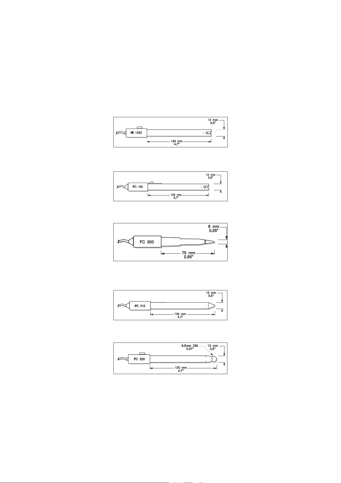
HI 1332B
120 mm
4.7"
12 mm
0.5"
"S" VERSION
HI 1332
120 mm
4.7"
12 mm
0.5"
FC 100
75 mm
2.95"
6 mm
0.25"
FC 200
120 mm
4.7"
12 mm
0.5"
FC 210
120 mm
4.7"
12 mm
0.5"
9.5mm DIA
0.37"
FC 220
Plastic-body (PES), double junction, refillable, combination pH electrode.
Use: general purpose.
FC 100B
Plastic-body (PVDF), double junction, refillable, combination pH electrode.
Use: general purpose for food industry.
FC 200B
Plastic-body (PVDF), open junction, conic, Viscolene, non-refillable,
combination pH electrode. Use: meat & cheese.
FC 210B
Glass-body, double junction, conic, Viscolene, non-refillable, combination
pH electrode.
Use: milk, yogurt.
FC 220B
Glass-body, triple-ceramic, single junction, refillable, combination pH
electrode. Use: food processing.
44
Page 45
110 mm
4.3"
12 mm
0.5"
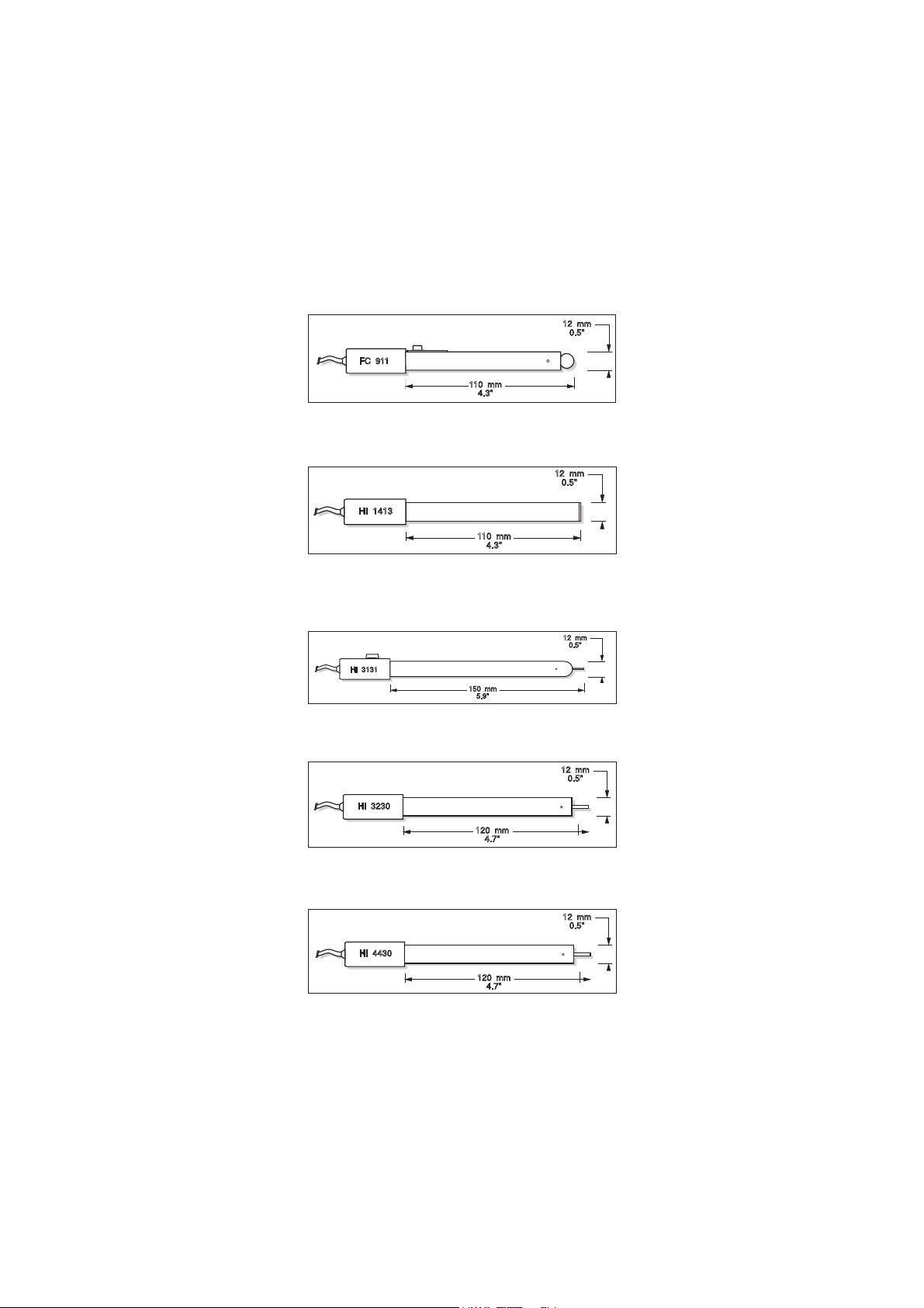
FC 911
FC 911B
110 mm
4.3"
12 mm
0.5"
HI 1413
150 mm
5.9"
12 mm
0.5"
"S" VERSION
HI 3131
120 mm
4.7"
12 mm
0.5"
HI 3230
"S" VERSION
120 mm
4.7"
12 mm
0.5"
HI 4430
"S" VERSION
Plastic-body (PVDF), double junction, refillable with built-in amplifier,
combination pH electrode. Use: very high humidity.
HI 1413B
Glass-body, single junction, flat tip, Viscolene, non-refillable, combination
pH electrode. Use: surface measurement.
ORP ELECTRODES
HI 3131B
Glass-body, refillable, combination platinum ORP electrode.
Use: titration.
HI 3230B
Plastic-body (PES), gel-filled, combination platinum ORP electrode.
Use: general purpose.
HI 4430B
Plastic-body (PES), gel-filled, combination gold ORP electrode.
Use: general purpose.
Consult the Hanna General Catalog for a complete and wide selection
of electrodes.
45
Page 46

EXTENSION CABLE FOR SCREW-TYPE ELECTRODES
CONNECT TO
SCREW TYPE
ELECTRODES
CONNECT TO THE
BNC SOCKET
OF THE METER
HI 7855 SERIES CABLE CONNECTORS
CONNECTOR AND 3.0 mm (0.12") CABLE WITH BNC
(SCREW TO BNC ADAPTER)
HI 7855/1 Extension cable 1 m (3.3') long
HI 7855/3 Extension cable 3 m (9.9') long
SMART ELECTRODES
HI 1615D combination pH electrode, glass-body, single junction, refillable
with built-in temperature NTC sensor and EEPROM for GLP
data storing.
HI 1616D combination pH electrode, glass-body, single junction,
gel-filled with built-in temperature NTC sensor and EEPROM
for GLP data storing.
HI 1617D combination pH electrode, glass-body, single junction, triple
ceramic, refillable with built-in temperature NTC sensor and
EEPROM for GLP data storing.
HI 1618D combination pH electrode, single junction, gel-filled with
built-in temperature NTC sensor and EEPROM for GLP data
storing.
HI 3619D combination ORP
HI 3620D combination ORP
/ Pt electrode, glass-body, single junction.
/ Pt electrode, single junction,gel-filled.
FC 201D combination pH electrode, single junction, with built-in
temperature NTC sensor and EEPROM for GLP data storing.
FC 212D combination pH electrode, double junction, with built-in
temperature NTC sensor and EEPROM for GLP data storing.
FC 231D combination pH electrode with knife (penetration 20mm/
0.79"), single junction, with built-in temperature NTC
sensor and EEPROM for GLP data storing.
FC 241D combination pH electrode with knife (penetration 35mm/
1.38"), single junction, with built-in temperature NTC
sensor and EEPROM for GLP data storing.
OTHER ACCESSORIES
HI 7662 Stainless steel Temperature probe with 1 m (3.3') cable
HI 710031 Rugged carrying case
HI 740028 1.5V AAA batteries (4 pcs)
HI 8427 pH and mV simulator
HI 931001 pH and mV simulator with LCD display
46
Page 47

HI 92000 Windows® compatible software.
HI 76405 Electrode holder
RECOMMENDATIONS FOR USERS
Before using these products, make sure they are entirely suitable for the
environment in which they are used.
Operation of these instruments in residential areas could cause
unacceptable interferences to radio and TV equipment, requiring the
operator to follow all necessary steps to correct interferences.
The glass bulb at the end of the pH electrode is sensitive to electrostatic
discharges. Avoid touching this glass bulb at all times.
During operation, ESD wrist straps should be worn to avoid possible
damage to the electrode by electrostatic discharges.
Any variation introduced by the user to the supplied equipment may
degrade the instruments’ EMC performance.
To avoid electrical shock, do not use these instruments when voltages at
the measurement surface exceed 24 Vac or 60 Vdc.
To avoid damage or burns, do not perform any measurement in
microwave ovens.
Windows® is registered Trademark of "Microsoft Co."
Hanna Instruments reserves the right to modify the design,
construction and appearance of its products without advance notice.
47
Page 48

Hanna Instruments Inc.
Highland Industrial Park
584 Park East Drive
Woonsocket, RI 02895 USA
Technical Support for Customers
Tel. (800) 426 6287
Fax (401) 765 7575
E-mail tech@hannainst.com
www.hannainst.com
Local Sales and Customer Service Office
Printed in EUROPE
(ROMANIA)
MAN98160Y 09/10
48
 Loading...