

Page 1
Instruction Manual
HI 9171 – HI 9174
HI 9181 – HI 9184
HI 9271 – HI 9274
Foodcare
Portable Microprocessor
Printing and Logging
Thermometers
Foodcare
PRT
5
PAPER
6
ALT
4
TEMP
2
TIME
1
http://www.hannainst.com
P
RINTIN
G
AN
D
LO
G
G
ING
TH
ERM
O
M
ETER
3
LOG
0
Compliance with the CE Directives
These Instruments are in
Page 2

Dear Customer,
Thank you for choosing a Hanna Product.
Please read this instruction manual carefully before using the instru-
ment. This manual will provide you with the necessary information for
a correct use of the instrument, as well as a precise idea of its
versatility. If you need more technical information, do not hesitate to
e-mail us at tech@hannainst.com.
These instruments are in compliance with directives
EN 50081-1 and 50082-1.
TABLE OF CONTENTS
PRELIMINARY EXAMINATION .........................................................3
GENERAL DESCRIPTION ................................................................ 3
LCD DISPLAY FUNCTIONAL DESCRIPTION .......................................4
FUNCTIONAL DESCRIPTION HI 9171 & HI 9174............................ 5
FUNCTIONAL DESCRIPTION HI 9181 & HI 9184............................ 6
FUNCTIONAL DESCRIPTION HI 9271C/F & HI 9274C/F ..................7
SPECIFICATIONS HI 9271 & HI 9274 ........................................... 8
OPERATIONAL GUIDE ................................................................... 9
PRINTING/RECORDING WITH HI 9171 & HI 9174 .......................15
PRINTING/RECORDING WITH HI 9271 & HI 9274 .......................18
PRINTING/LOGGING WITH HI 9181 & HI 9184 ...........................20
DATA TRANSFER TO PC............................................................... 30
SELF-DIAGNOSTIC FUNCTIONS .................................................... 31
MEMORY ORGANIZATION ............................................................31
PRINTER MAINTENANCE ............................................................. 32
BATTERY REPLACEMENT.............................................................. 34
CALIBRATION .............................................................................35
TEMPERATURE PROBES .............................................................. 36
UN-HOUSED NTC SENSORS ........................................................38
ACCESSORIES ............................................................................ 40
WARRANTY ................................................................................41
CE DECLARATION OF CONFORMITY ..............................................43
ISO 9000 Certified
Company since 1992
2
Page 3

PRELIMINARY EXAMINATION
Remove the instrument from the packing material and examine it
carefully to make sure that no damage has occurred during shipping.
If there is any damage, notify your Dealer or the nearest Hanna
Customer Service Center.
Each Printing Thermometer is supplied with:
• Paper Rolls (5 pcs)
• 1.5V x AA size Batteries (4 pcs)
• Rugged Carrying Case
Note: Save all packing material until you are sure that the instru-
ment functions correctly. All defective items must be returned
in its original packaging together with the supplied accessories.
GENERAL DESCRIPTION
These Hanna portable thermometers with built-in printers are microprocessor-based to accurately measure temperature and record data.
The instrument housing is made of rugged and lightweight material,
specifically designed for the food industry.
Measurements can be performed with lab-grade precision in the field
without compromising accuracy. A 12VDC adapter can also be used to
power the unit for prolonged use.
Common features include: use of precalibrated and completely interchangeable probes, user-selectable printing/logging intervals, printing
on plain paper, automatic shut-off capability, low battery warning,
clock and calendar (HI 9171, HI 9174, HI 9181 and HI 9184),
memorization of logged values (HI 9181 and HI 9184), all opera-
tions password protected (HI 9171, HI 9174, HI 9181 and HI 9184)
and 2 year warranty.
HI 9181 and HI 9184 have a memory capacity of 16,000 individual
temperature readings with selectable recording intervals. Using the
HI 9200 infrared transmitter, all the recorded data can be fed to a PC
for reproduction, storage or elaboration without having to connect and
disconnect cables and cords.
3
Page 4
Different versions are divided into:
HI 9171, HI 9174, HI 9181, HI 9184, HI 9271C and HI 9274C
measuring in degrees Celsius, and HI 9271F and HI 9274F for
Fahrenheit measurements.
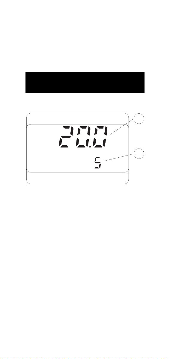
LCD DISPLAY
FUNCTIONAL DESCRIPTION
1
°C
LOG INTV
1. Primary Display
2. Secondary Display
DATE
TIME
LO BAT
2
4
Page 5
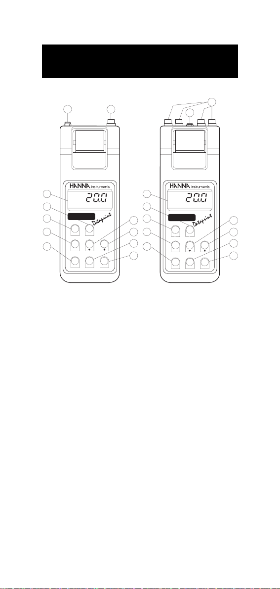
FUNCTIONAL DESCRIPTION
HI 9171 & HI 9174
PAPER
TIME
2
THERMOMETER
HI 9174
443
1
PRINTING
0
RUN
2
°C
3
4
Foodcare
5
6
PRT
7
ALT
TEMP
1
°C
3
4
Foodcare
5
PRINTING
THERMOMETER
6
PAPER
HI 9171
RUN
TIME
1
8
6
9
10
3
0
7
11
TEMP
PRT
ALT
556
221
1. Temperature Probe Connector(s)
2. Socket for External 12VDC Power Supply
3. Liquid Crystal Display
4. PAPER (to move paper up)
5. PRT (to obtain printout of current date, time and temperature)
6. ALT (alternate function key)
7. TEMP (to read temperature and to reactivate meter when in
standby mode)
8. (to scan data or to set date, time and printing interval, or
to select channel # for HI 9174 only)
9. (to scan data or to set date, time and printing interval, or
to select channel # for HI 9174 only)
10. TIME (to display time and printing interval)
11. RUN (to enter and exit recording mode)
8
9
10
11
5
Page 6

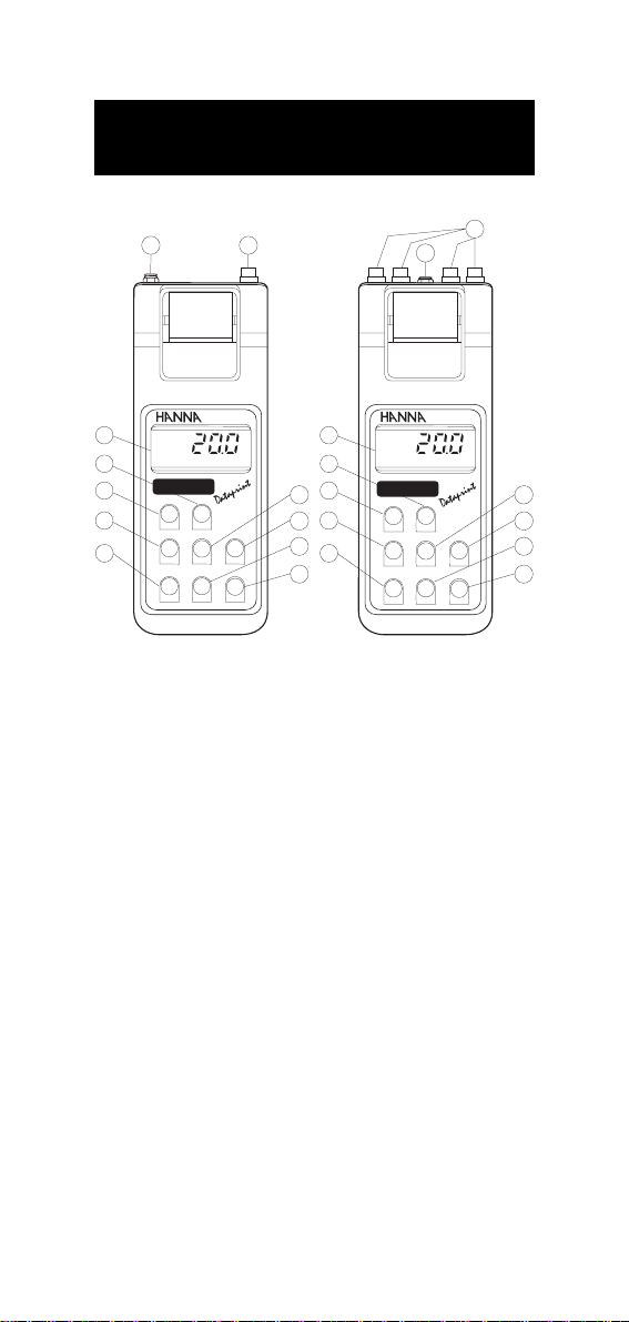
FUNCTIONAL DESCRIPTION
HI 9181 & HI 9184
2
°C
3
4
Foodcare
5
6
PRT
7
ALT
TEMP
1
°C
3
4
Foodcare
5
PRINTING
AND LOGGING
THERMOMETER
6
PAPER
HI 9181
4
LOG
TIME
1
8
6
9
10
3
0
7
11
TEMP
PRT
ALT
556
221
1
2
PRINTING
AND LOGGING
THERMOMETER
PAPER
HI 9184
3
4
LOG
0
TIME
1. Temperature Probe Connector(s)
2. Socket for External 12VDC Power Supply
3. Liquid Crystal Display
4. PAPER (to move the paper up)
5. PRT (to obtain printout of current date, time and temperature)
6. ALT (alternate function key)
7. TEMP (to read temperature and to reactivate meter when in
standby mode)
8. (to scan data or to set date, time and printing interval, or
to select channel # for HI 9174 only)
9. (to scan data or to set date, time and printing interval, or
to select channel # for HI 9174 only)
10. TIME (to display time and printing interval)
11. LOG (to enter and exit the logging and printing mode)
8
9
10
11
6
Page 7
FUNCTIONAL DESCRIPTION
HI 9271C/F & HI 9274C/F
2
instrum nts
PAPER
UP
PRINT
1
e
PRINTING
THERMOMETER
HI 9274C
-50°C .....+150.0°C
DOWN
instrum nts
PAPER
UP
PRINT
1
e
PRINTING
THERMOMETER
HI 9271C
-50°C .....+150.0°C
DOWN
°C
3
4
Foodcare
5
8
6
9
10
11
ON/OFF
7
INTV
0.1/1 LOG
2
°C
3
4
Foodcare
5
6
ON/OFF
7
INTV
0.1/1 LOG
1. Temperature Probe Connector(s)
2. Socket for External 12VDC Power Supply
3. Liquid Crystal Display
4. PAPER (to move paper up)
5. ON/OFF (to switch meter on/off or to reactivate meter when
in standby mode)
6. INTV (to select printing interval)
7. 0.1/1 (to select resolution)
8. UP (to set printing interval or to select channel # for
HI 9274 only)
9. DOWN (to set printing interval or to select channel # for
HI 9274 only)
10. PRINT (to obtain printout of sample # and temperature)
11. LOG (to enter and exit recording mode)
8
9
10
11
7
Page 8

SPECIFICATIONS
HI 9171 – HI 9174 HI 9271F
HI 9271C – HI 9274C HI 9274F
HI 9181 – HI 9184
Range -50.0 to 150.0°C -55.0 to 300.0°F
Resolution 0.1°C / 1°C 0.1°F / 1°F
Accuracy ±0.4°C ±0.8°F
(@ 20°C/68°F) for one year, excluding probe error
Typical EMC Deviation ±0.4°C ±0.8°F
Power Supply 4x1.5V AA size, max. 500 hours with 60' printing
Auto Shut-off After 5 minutes of non-use
Channels 1 for HI 9171, HI 9271, HI 9181 and
Printer Low-power impact belt type, 14 characters per line
Printing/Logging 1, 2, 5, 10, 15, 30, 60, 120 and 180 minutes
Intervals
Environment 0 to 50 °C (32 to 122°F)
Dimensions 220 x 82 x 66 mm (8.7 x 3.2 x 2.6")
Shipping Weight 1.4 kg (3.1 lb.)
interval. Socket for 12VDC adapter
4 for HI 9174, HI 9274, HI 9184
using 38 mm plain paper
Max. 95% RH non-condensing
8
Page 9
OPERATIONAL GUIDE
INITIAL PREPARATION
Each meter is supplied complete with batteries. Remove the back
cover, unwrap the batteries and install them while paying attention to
the polarity (see also page 34).
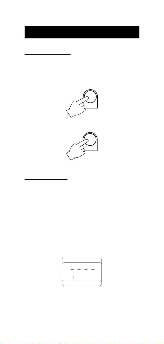
To switch HI 9171, HI 9174, HI 9181 and HI 9184 on, press TEMP.
TEMP
To switch HI 9271 and HI 9274 on, press ON/OFF.
ON/OFF
If the meter does not switch on check the batteries.
PROBE CONNECTION
Choose the most appropriate temperature probe(s) for your application (see page 36) and connect it (them) to the probe connector(s)
located on the top of the instrument. All the probes have been
precalibrated at the factory and no calibration is needed.
HI 9171, HI 9181 and HI 9271 take a single probe while HI 9174,
HI 9184 and HI 9274 can take up to four probes.
With the meter facing you, channel #1 is the first connector on the
top left corner.
If neither a temperature probe nor a calibration test plug is connected
to the instrument, the meter will display "°C ----" to alert the user.
°C
CH
This could also indicate that probe cable is damaged. "CH" and the
channel number are displayed together (HI 9174, HI 9184, HI 9274
only).
9
Page 10

Note: To ensure accuracy, it is recommended that the temperature
probes be connected to consecutive channels beginning with
channel #1. For example, if only one probe is to be used,
connect it to channel #1. If 2, 3 or 4 probes are used, connect
them to channels 1, 2, 3, and 4 in ascending order.
AUTO SHUT-OFF
To maximize battery life the display is automatically switched off after 5 minutes of
non-use. However, the meter will continue to
TEMP
monitor the temperature if in recording/logging mode.
To revive the display, press any key (except ALT with HI 9171,
HI 9174, HI 9271 and HI 9274).
SETTING DATE, TIME, PRINTING OR LOGGING
INTERVAL (FOR HI 9171, HI 9174, HI 9181
& HI 9184 ONLY)
Turn the instrument on by pressing the TEMP
TEMP
key.
Press ALT and TIME simultaneously. These instruments have a pass-
word security feature. The default password is 0000. When the meter
is used for the first time, it allows time and date to be set until a
password is entered. If a password has been entered (see page 12)
"----" appears on display and one can only proceed after digiting the
password. Otherwise the display will show the date setting with the
year blinking (shown as the last 2 digits of the year i.e. 95 = 1995).
ALT
+
TIME
DATE
Use or to select the year.
10
Page 11
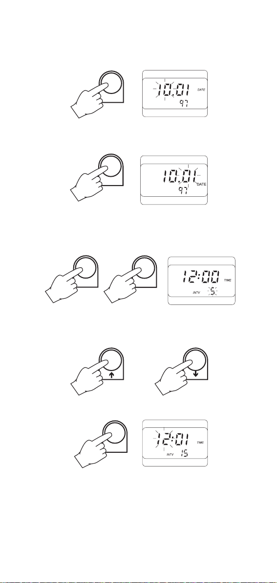
When the correct year is selected, press TIME to memorize it. The
month will start blinking.
TIME
Similarly set month by or . Press TIME and the day will start
blinking.
TIME
Use or to select the correct day.
Press the ALT and the TIME keys simultaneously. The display will
switch to the clock mode, and the printing interval will blink.
+
ALT
TIME
Any interval can be selected from 1, 2, 5, 10, 15, 30, 60, 120 to 180
minutes by using or .
Memorize the interval by pressing TIME. The hour will start blinking.
TIME
11
Page 12
To select the hour press or (24 hour clock) and press TIME
once more to memorize it. The minutes will start blinking.
TIME
Use or to select the minutes.
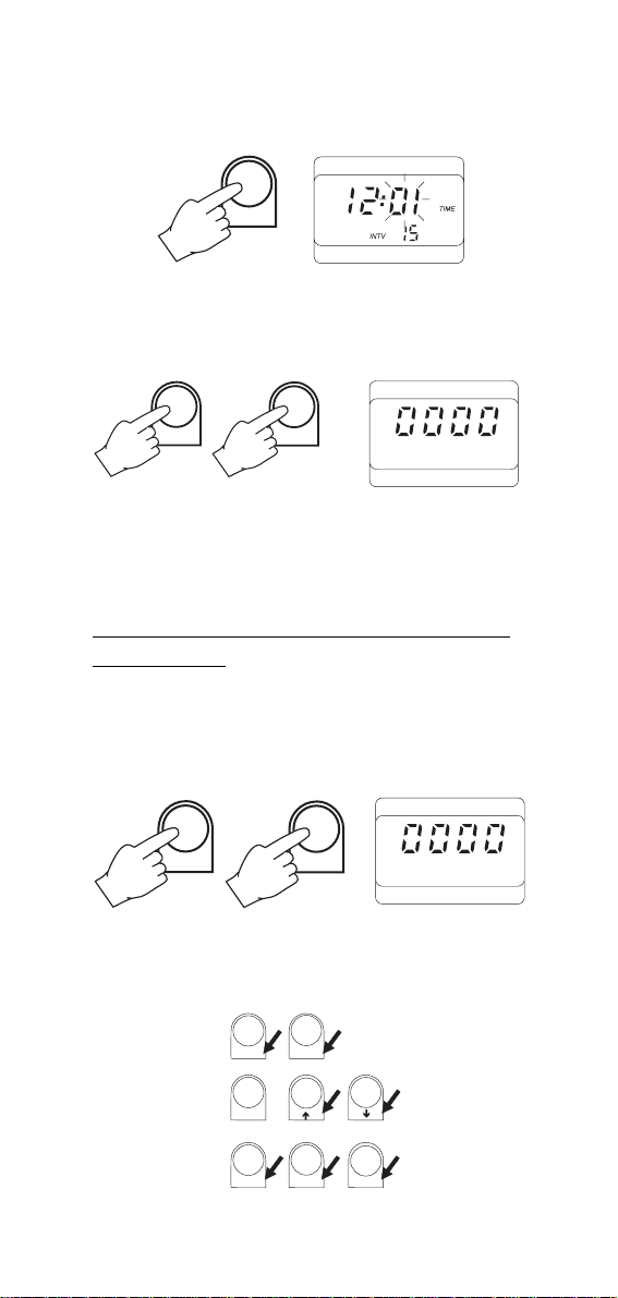
Press the ALT and TIME keys simultaneously. The instrument will now
ask for the password and display "0000".
+
ALT
TIME
To return to normal operation enter the password or press the ALT and
TIME keys again if the password is not to be changed.
The new date, time and printing interval are now stored in the
memory even when the meter is switched off.
SETTING THE PASSWORD (HI 9171, HI 9181, HI 9174
& HI 9184 ONLY)
The password is represented by a 4 digit number each selectable from
0 to 6.
By pressing the ALT and the TIME keys at the end of the time/date
setting procedure, four zeros appear on the LCD.
+
ALT
TIME
If you wish to enter a password, press any of the keys corresponding
to a number. These numbers are printed on the bottom right hand
side of the keys as shown below:
56
56
PRT
PAPER
43
2
TIME
12
43
012
1
0
LOG
ALT
TEMP
Page 13
If no password is necessary, leave the default password as 0000 by
C
pressing and holding ALT down and then pressing TIME.
Once a password has been entered, it is automatically stored in
memory. By pressing ALT and TIME simultaneously the display will
switch back to normal operation.
+
ALT
TIME
Note: If the password is not known or forgotten, remove the batteries
for two minutes and the password is reset to the default 0000.
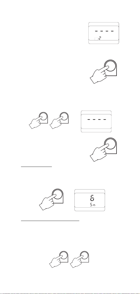
ENTERING THE PASSWORD
When the display shows "----" it means that the password has to be
entered. Press the keys corresponding to the password, e.g. for "1256"
press the TIME, TEMP, PRT and PAPER keys in that sequence. If the
wrong key is pressed, once all four digits are filled on the LCD, the
meter will again show "----" so that the entire password can be reentered.
VIEWING TEMPERATURE, TIME & DATE (FOR HI 9171,
HI 9174, HI 9181 & HI 9184 ONLY):
To view the date press the key.
DATE
To view the time and the printing interval press TIME.
TIME
INTV
TIME
To view temperature press TEMP.
°C
TEMP
HANNEL
13
CH
Page 14
Using the or keys select channel (HI 9174 and HI 9184
only).
If "°C ----" is displayed, it indicates that the temperature probe or
calibration test plug is not connected. This may also indicate the
possibility of a damaged probe cable. The channel # is displayed
together with "CH" (HI 9174 and HI 9184 only).
°C
CH
SETTING THE PRINTING INTERVAL FOR HI 9271 &
HI 9274 ONLY
Turn the meter on by pressing ON/OFF.
ON/OFF
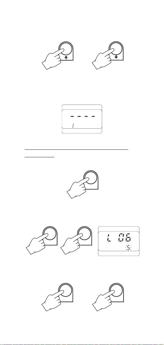
Press the INTV and the UP keys and hold down the INTV key. The
display will show the log number while the printing interval will start
blinking.
INTV
UP
INTV
Any interval can be selected from 1, 2, 5, 10, 15, 30, 60, 120 and
180 minutes by using the UP and DOWN keys.
UP
14
DOWN
Page 15

Release the INTV key to exit this mode.
INTV
SETTING THE MEASUREMENT RESOLUTION (HI 9271 &
HI 9274 ONLY)
Press the 0.1/1 key to select 0.1° or 1° resolution.
°C
0.1/1
CH
With HI 9274, all four channel readings automatically change by
pressing this key.
To return the reading to its original resolution, simply press the 0.1/1
key again.
PRINTING/RECORDING
WITH HI 9171 & HI 9174
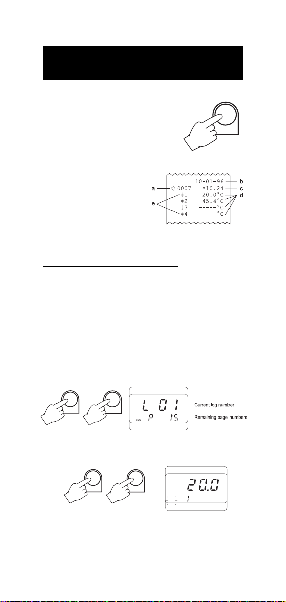
To print the measured values shown on the
display, press PRT. This function can be activated in normal operation mode as well as
PRT
during recording mode (see below). When in
measurement mode, the printout provides the
following information:
a – Running sample number
b – Date (DD-MM-YY)
c – Time (HH-MM)
d – Temperature value(s)
e – Channel numbers (HI 9174 only)
RECORDING AT AN INTERVAL
Ensure that the appropriate recording interval has been set (see
Operational Guide on page 9).
15
Page 16
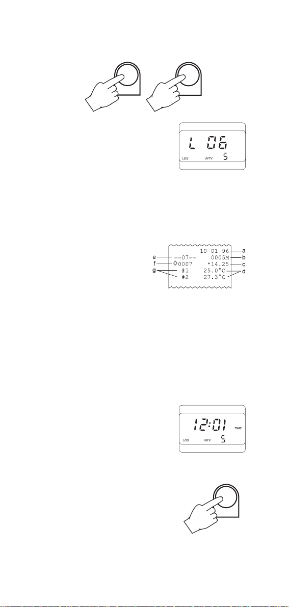
Press ALT and RUN simultaneously to enter the recording mode.
+
ALT
The log number and the interval time will
appear for a few seconds on the display to
indicate the correct operational mode.
The meter will print the measurements taken in that moment, and
will print at the selected interval thereafter until ALT and RUN are
pressed again. The password is also requested to stop printing (unless
it remained at default 0000).
Each printout provides the following information:
a – Date (DD-MM-YY)
b – Printing interval in minutes
c – Time (HH-MM)
d – Temperature value(s)
e – A running log number
f – Running sample number (in that particular log)
g – Channel number(s)
HI 9174 will print only the values of the probes connected. If probes
are added to the remaining channels during the recording mode, the
data from the additional probes will not be printed. Data from remaining channels can only be added if the recording mode is exited
and re-entered. A blinking "CH" will appear on the display next to the
channel numbers not being utilized and/or recorded.
When the meter is in recording mode "LOG"
is displayed on the bottom left corner of the
LCD together with time and the printing interval.
If no keys are pressed, the meter goes to standby mode to prolong the
battery life while the recording function remains active.
RUN
To reactivate the display press TEMP.
TEMP
Notes:
• Once in the recording mode, the printer cannot be stopped unless
the password is entered (unless the password is 0000).
16
Page 17
• The interval cannot be changed during recording mode. Exit the
recording mode first (press ALT and LOG and enter the password)
before setting the new interval.
+
ALT
LOG
• If PRT is pressed while in logging mode,
a printout is produced without affecting
PRT
the running sample number.
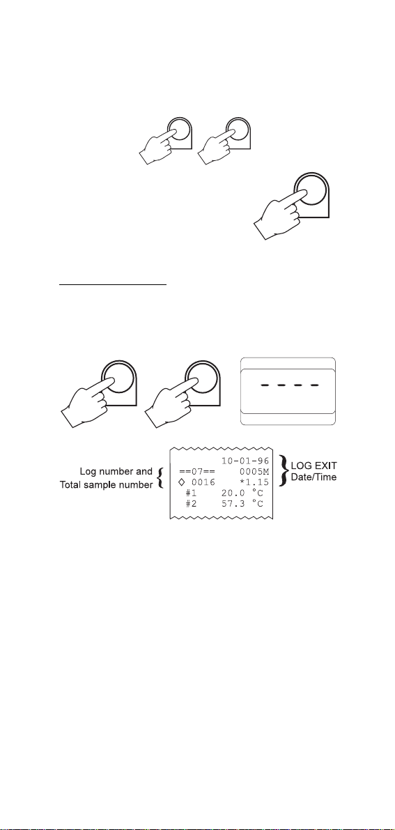
TO STOP RECORDING
Press ALT and LOG simultaneously. If a password has been entered
the printer will require the operator to enter the correct password
whereupon it will generate a log exit status printout.
+
ALT
LOG
LOG
Note: If the password is unknown or forgotten, remove the batteries
for two minutes to stop printing and reset the password to
0000. Likewise, the running log number can also be reset.
17
Page 18

PRINTING/RECORDING
WITH HI 9271 & HI 9274
To print the measured values press PRINT.
Each printout provides the following information:
a – The total accumulative time
b – Temperature value(s)
c – Channel numbers (HI 9274 only)
d – Running sample number
RECORDING AT AN INTERVAL
Ensure that the appropriate recording interval has been set (see
Operational Guide on page 9).
PRINT
Press the LOG key to enter the recording mode.
LOG
The log number and the interval time will
appear for a few seconds on the display to
indicate the correct operational mode.
The meter will print the measurements taken
in that moment, and will print at the selected
interval thereafter until the ON/OFF key is
pressed again.
ON/OFF
The printout provides the following information:
a – A running log number
b – A running sample number (in
that particular log)
c – Channel numbers (HI 9274 only)
d – Printing interval indicator in minutes
e – The accumulated time since printing started (HH.MM)
f – Temperature value(s)
HI 9274 will print only the values of the
probes connected. If probes are added to the
remaining channels during the recording
°C
CH
LOG
mode, the data from the additional probes
will not be printed. Data from remaining channels can only be added
if the recording mode is exited and re-entered. A blinking "CH" will
18
Page 19
appear on the display next to the channel numbers not being utilized
and/or recorded.
When the meter is in recording mode "LOG"
is displayed on the bottom left corner of the
LCD together with temperature.
°C
LOG
CH
If no keys are pressed, the meter goes to standby mode to prolong the
battery life.
Notes:
• If the PRINT key is pressed while still in
recording mode, a printout is produced
PRINT
without affecting the running number.
• Once in recording mode, the printing interval cannot be changed. Exit the
recording mode first by pressing ON/OFF
ON/OFF
and reset the new interval.
TO STOP RECORDING
To quit recording mode, press ON/OFF. This
will generate a recording exit status printout.
Log number
ON/OFF
--07-- 0005M
<>0016 *1.15
Total sample number
Exit printing interval
& accumulative time
19
Page 20
PRINTING/LOGGING
WITH HI 9181 & HI 9184
To print the measured values shown on the
display, press PRT. This function can be activated in normal operation as well as during
logging and scanning data on display (see
page 23). When in measurement mode, the
printout provides the following information:
a – Running sample number
b – Date (DD-MM-YY)
c – Time (HH-MM)
d – Temperature value(s)
e – Channel numbers (HI 9184 only)
LOGGING MODE WITHOUT PRINTING
This function is particularly useful when measurements have to be
taken continuously even in the absence of an operator over a long
period of time. In this mode data will be stored directly into memory.
Set the appropriate logging interval (see page 9).
Press the ALT and LOG keys simultaneously to enter the logging
mode. The current log number and remaining page numbers will
appear for a few seconds on the display to indicate the correct
operational mode. The printer will print a complete set of data and
the "LOG" symbol will appear on the secondary LCD.
PRT
+
ALT
LOG
To continue logging without printing, press ALT and PAPER at the
same time and the "LOG" symbol on display will start to blink.
ALT
+
PAPER
°C
LOG
CH
HI 9184 will print only the values of the probes connected. If probes
are added to the remaining channels during the recording mode, the
data from the additional probes will not be printed. Data from re-
20
Page 21
maining channels can only be added if the
recording mode is exited and re-entered. A
blinking "CH" will appear on the display next
°C
CH
LOG
to the channel numbers not being utilized
and/or recorded.
After approximately 5 minutes the display will switch off but the
logging function remains active.
To reactivate the display press TEMP.
If you wish to restart printing press the ALT
TEMP
and PAPER keys simultaneously again.
Notes:
• Once in the logging mode, the interval cannot be changed. Exit
the logging mode by pressing ALT and LOG and entering the
password before setting the new interval.
+
ALT
LOG
LOG
• If PRT is pressed while in logging mode, a
printout is produced without affecting the
running sample number.
PRT
SAMPLE NUMBER
During logging it is possible to know the running sample number.
Press the LOG key twice and the display will show the number of
values that have been taken in the current log.
2 x
LOG
LOG
LOGGING MODE WITH PRINTING
This function is useful in a variety of applications from unsupervised
monitoring to satisfying regulatory requirements. In addition to the
printouts, the measurements are also stored into the memory.
Press the ALT and LOG key simultaneously to enter the logging mode.
+
ALT
21
LOG
Page 22
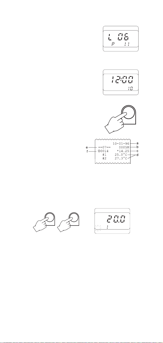
The current log number and the remaining
page numbers will appear for a few seconds
on the display to indicate the correct opera-
LOG
tional mode. The printer will print a complete
set of data and the "LOG" symbol will appear
on the secondary LCD.
If no key is pressed, the display goes blank
after about 5 minutes and comes back to life
only to print the next batch of data. During
printing, the display shows the time,
LOG INTV
TIME
preselected interval and the “LOG” symbol.
To reactivate the display press the TEMP key.
Each printout provides the following informa-
TEMP
tion:
a – Date (DD-MM-YY)
b – Printing interval in minutes
c – Time (HH-MM)
d – Temperature value(s)
e – A running log number
f – A running sample number (in that particular log)
It is always possible to switch from the logging with printing function
to the logging without printouts. Press ALT and PAPER at the same
time and the "LOG" symbol will start to blink to indicate that the data
are now stored into memory but no longer printed.
°C
+
ALT
PAPER
LOG
CH
Notes:
• It is recommended to use the external power supply during logging with printing mode, especially when many printout are
going to be taken.
• Before proceeding with logging with printing, make sure there is
enough paper for your measurements. When the paper is run out
the meter will not advise the operator and the printouts could be
lost. If this happens, data will continue to be stored into memory,
and it is always possible to print them at later time (see page
25).
22
Page 23
• It is possible to insert a new paper roll during logging session (see
IT
e
page 32).
• Once in the logging mode, the printer cannot be stopped unless
the password is entered (unless the password is 0000).
• The interval cannot be changed during logging mode.
Exit the recording mode by pressing ALT and LOG and entering the
password before setting the new interval.
+
ALT
LOG
LOG
• If PRT is pressed while in logging mode,
a printout is produced without affecting
the running sample number.
PRT
TO STOP LOGGING
Press the ALT and the LOG keys simultaneously and enter the password. This will generate an exit status printout.
+
ALT
LOG
Log number
Total sample number
==07== 0005M
10-01-96
0016 *16.25
#1 20.0 °C
#2 57.3 °C..
LOG EX
Date/Tim
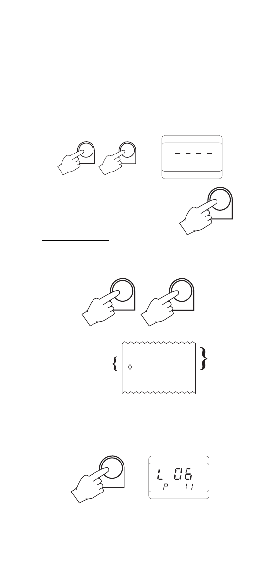
TO SCAN STORED DATA ON DISPLAY
Press the LOG key. The display will show the log number and the
remaining page numbers.
LOG
23
Page 24
While pressing the ALT key, press the key until the log number to
scan appears on the secondary display. The primary display will show
the number of samples in that particular log.
+
ALT
Press the ALT and the TEMP keys simultaneously. This now shows the
date when log started.
+
ALT
TEMP
Press the key and the time of the most recent sample will be
displayed.
Press the key and the temperature will be displayed.
Continue pressing the key to display one by one all the memorized data of the same log in the above sequence i.e. time and
temperature.
Press the key to revert back to sampling time and scan the
samples.
To exit from the recall mode press the LOG
key.
LOG
Note: this mode will not alter data already
in the memory.
24
Page 25
TO PRINT STORED DATA
Once a log number is selected (see
"TO SCAN STORED DATA ON DISPLAY"
on page 23) you can print all or part
of that logged section by pressing the
ALT and PRT keys. The printer will
start to print the logged section beginning with the selected sample number
without altering the content of the
memory.
ALT
ALT
+
+
PRT
Note: It is always possible to print
only the sample shown on the
PRT
display by pressing the PRT key.
Note: Before proceeding with printing, make sure there is enough
paper for the data to be printed. When the paper is finished
the meter will not advise the operator and the printouts could
be lost. If this happens, stop
the printer by pressing ALT and
ALT
+
PAPER
PAPER simultaneously.
Insert a new paper roll and repeat the instructions above
starting from the last printed sample number (see chapter
"PRINTER MAINTENANCE" on page 32 for changing the paper
roll).
WORKING EXAMPLE (HI 9181 & HI 9184 ONLY)
The following is a step by step procedure of a typical monitoring
situation where we have assumed that the batteries have been inserted and the date and time correctly set.
In this example, the meter stores the temperature every 2 minutes. It
will log 10 samples but print only 3, then displays the data contained
in sample number 1 and prints samples 5 through 10.
Example:
Step One - Setting the printing/logging interval at 2 minutes:
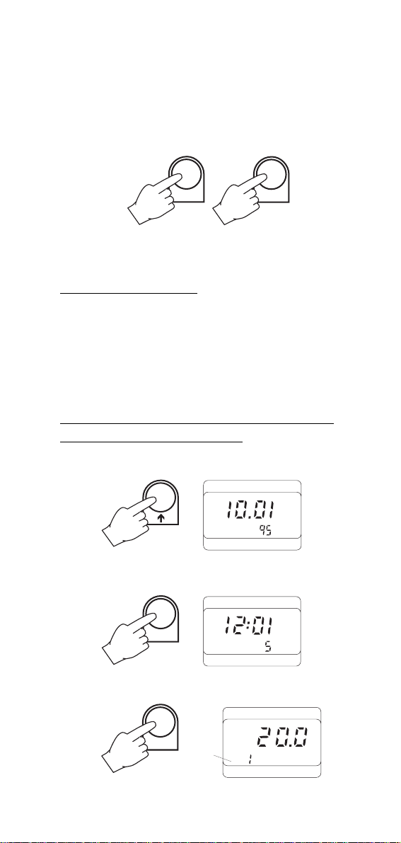
Press ALT and TIME. The display will now ask for the password (unless
it was left at 0000).
ALT
+
°C
TIME
CH
25
Page 26

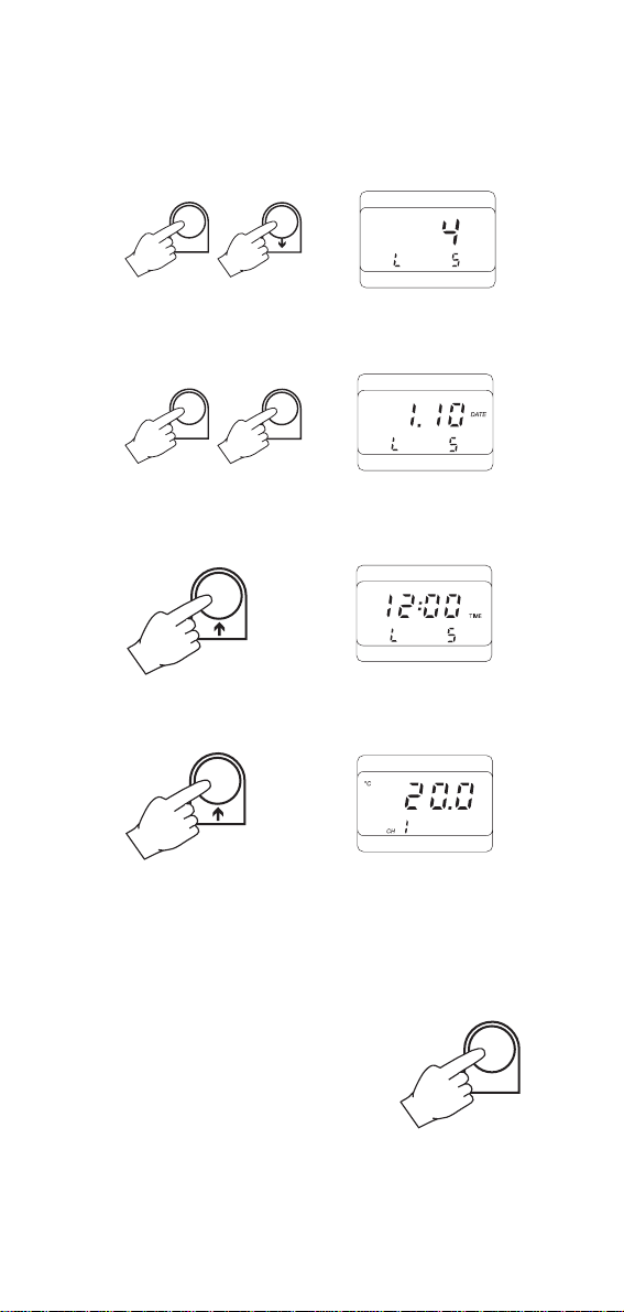
Enter password 3434 using the and keys.
3
4
34
Press ALT and TIME again. The time will appear on the primary
display with an intermittent number representing the printing/logging
interval.
ALT
+
TIME
TIME
INTV
Press either the or keys until "2" appears blinking.
TIME
INTV
Press the ALT and TIME keys twice to exit. The display will now show
the current time together with the selected interval of 2 minutes.
ALT
+
TIME
TIME
INTV
Step Two - Entering the log mode:
Press ALT and LOG. Initially, "L 01" will appear on the primary
display.
+
ALT
LOG
LOG
The meter is now in the printing/logging mode utilizing log number
1, page 16. "LOG" and P 15 shown in the secondary display indicate
that the meter has entered the log mode, and has 15 available pages
of memory remaining. After the initial printout, the time and printing/
logging interval will reappear.
TIME
INTV
26
Page 27

Press the LOG key to view the running log and page numbers.
LOG
LOG
Press the LOG key again to view the running sample number.
LOG
LOG
Step Three - Stopping the printer during the log mode:
After the third printout is completed, press the ALT and PAPER keys. At
this point the meter will continue to log data every 2 minutes but will
no longer print any information. "LOG" will blink on the secondary
display for the remainder of "L 01" (log number 1).
+
ALT
PAPER
LOG
Note: If the display is shut off, press TEMP to reactivate it and then
press LOG twice to view the running sample number.
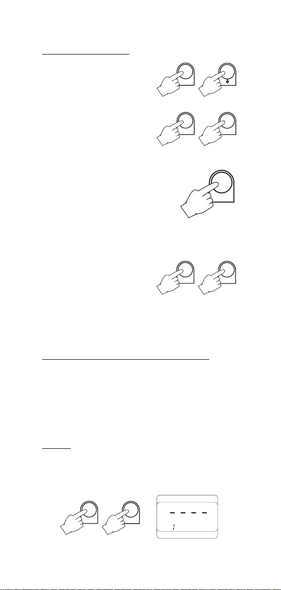
Step Four - Leaving the log mode:
Once the number of samples stored in memory has reached 10, press
the ALT and LOG keys. The meter will demand a password.
+
ALT
LOG
LOG
Enter the password 3434 using the and keys.
3 4 3 4
The meter will exit the log mode after generating a log exit status
printout.
10-01-96
==01== 0002M
0010 *00.18
27
Page 28

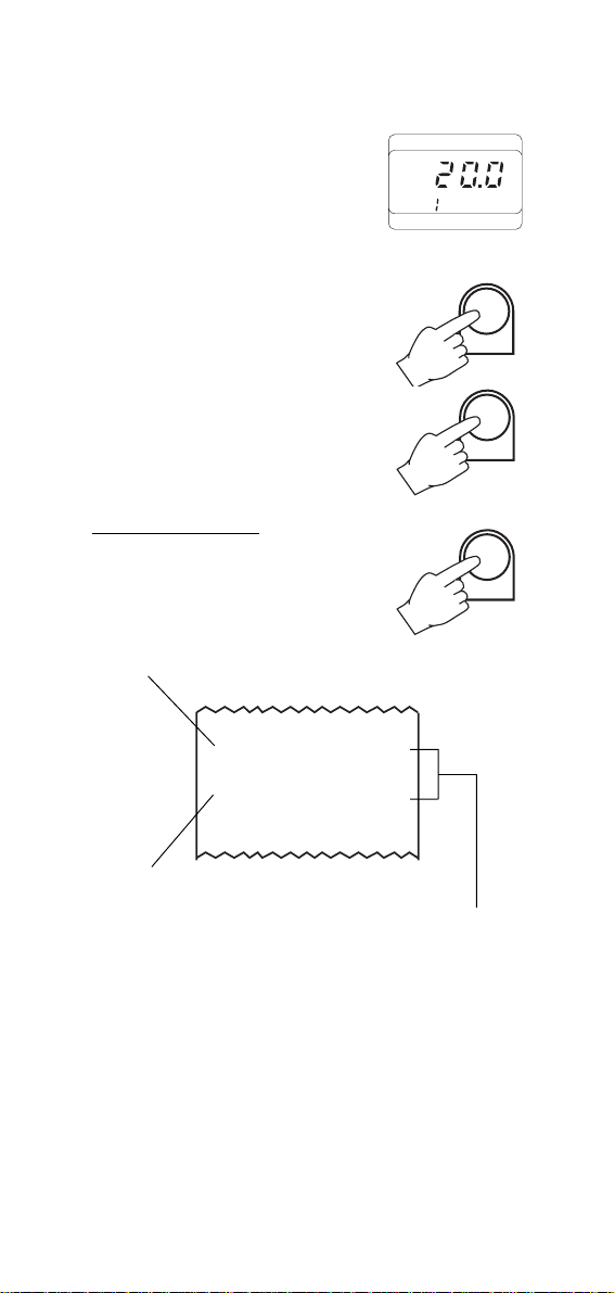
Step Five - Reviewing the stored data in log number 1:
Press LOG to enter the memory recall mode. The next available log
and page number will be shown on the display.
LOG
Press the ALT and keys until the number 10 and "L1" appear,
indicating that a total of 10 samples were recorded in log number 1.
+
ALT
To view the data stored in log number 1 first use the and keys
to scroll through the sample numbers.
Once the desired sample number is displayed, press the ALT and
TEMP keys. The date in which that sample was taken will appear first.
+
ALT
TEMP
Press the key to view the time.
Press the key again to view the temperature.
°C
CH
28
DATE
TIME
Page 29

With HI 9184 when more than one probe have been connected, press
the key to view the other channels values.
Step Six - Printing the stored data (samples 5 through 10):
Press and hold the ALT key and press the key until the total
number of samples recorded in log number 1 is displayed.
Scroll through the sample numbers by using either the or keys
until number "5" appears.
Press the ALT and PRT keys. The meter will automatically printout
sample numbers 5, 6, 7, 8, 9 and 10 consecutively.
+
ALT
PRT
29
Page 30

DATA TRANSFER TO PC
(HI 9181 & HI 9184 only)
HI 9181 and HI 9184 contains infrared emitting circuitry. Set the meter to TIME mode and
place it on a HI 9200 Infrared Transmitter
(ensuring that the infrared LEDs are placed on
top of each other). The logged data can be
downloaded to your PC through the HI 9200's
RS232 port.
During the data transfer the instrument displays "r 232".
Using the HI 9200 Infrared Transmitter, all recorded data can be fed
to your Personal Computer for easy reproduction, storage or elaboration without having to connect and disconnect cables between the
meter and your PC.
Data can be further elaborated with the new optional HI 92000
Windows® compatible application software.
HI 92000 allows use of commonest spread sheet programs (e.g.
Excel, Lotus 1-2-3) and offers a variety of features with an on-line
help routine. To install HI 92000, you need a 3.5" drive and a
couple of minutes to follow the short instructions conveniently printed
on the disk label.
TIME
Windows® is a registered Trademark of "Microsoft Co."
Excel© Copyright of "Microsoft Co."
Lotus 1-2-3© Copyright of "Lotus Co."
30
Page 31

SELF-DIAGNOSTIC FUNCTIONS
HI 9171, HI 9174, HI 9181, HI 9184, HI 9271 and HI 9274 are
factory programmed to automatically diagnose a fault and inform the
user by displaying an error code on the LCD.
Error codes are:
PEr0, PEr1, PEr2 = Short circuit on the system, the meter should be
returned for repair (see Warranty section).
PEr3 = Printer mechanism fault - repair needed (see Warranty
section).
PEr4 = Printer clutch jammed - reset the printer (see page 33).
PEr9 = Printer jammed - reset the printer (see page 33).
MEMORY ORGANIZATION
(HI 9181 & HI 9184 only)
Capacity
16,000 data samples, divided into 16 pages.
Capacity per page
1000 data with 1 channel monitored;
500 data with 2 channels monitored (four channels versions only);
250 data with 3 or 4 channels monitored (four channels versions only).
Each time a new logging mode is entered, it automatically starts a
new page. Once all 16 pages are used up, the meter will overwrite
the first lot. During logging, the meter automatically returns to the
oldest page in the memory and if it contains data, it will overwrite it.
In this case the first log will not correspond to the oldest set of data
It is recommended to periodically “clean” the memory. Save the data
in a PC if you need to keep a record and then disconnect the batteries
for about 1 minute. If you do this, remember to reset the time and
date, once the batteries have been inserted again.
ATTENTION
Data is stored into memory until batteries are removed. If replacement of the batteries is needed and data is not to be lost, first plug in
an external 12VDC power supply and then proceed with battery
replacement as described on page 34. Only once batteries have been
replaced, it is possible to unplug the power supply without losing the
previously memorized data.
31
Page 32
PRINTER MAINTENANCE
TO CHANGE THE INK CARTRIDGE
When printouts become faint, it might be necessary to change the ink
cartridge. Contact your dealer or the nearest Hanna Service Center for
this.
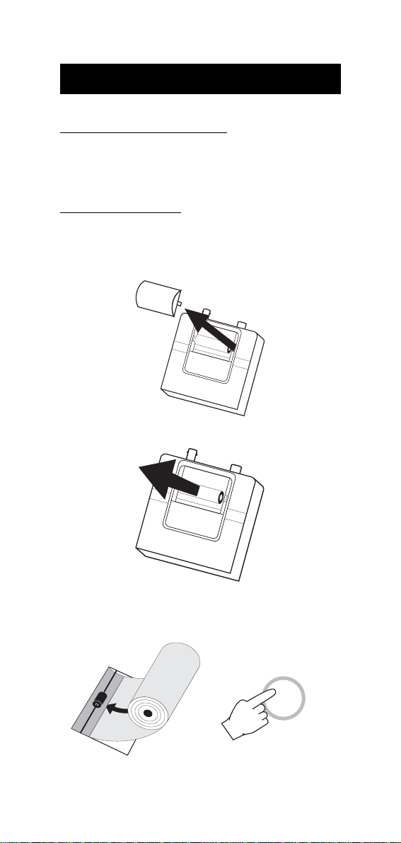
TO INSERT PAPER ROLL
HI 9171, HI 9174, HI 9181, HI 9184, HI 9271 and HI 9274 use
plain 38 mm wide paper rolls. To insert a new roll gently pull out the
printer cover.
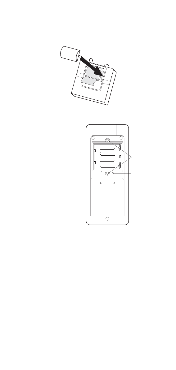
Take out the used paper cylinder.
Insert the paper edge in the printer slot and feed the paper through
by pressing the PAPER key.
PAPER
32
Page 33
Allow about 5 cm (2") of paper to exit from the printer and then
replace the cover.
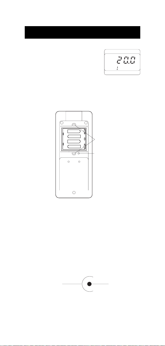
TO RESET THE PRINTER
Take the battery cover off by
removing the screws on the
back of the meter. Using a blunt
-
1.5V
pencil press the black reset button. This will reset the printing
mechanism.
Before replacing the battery
cover, investigate likely cause
of the printer jam (e.g. the paper might be caught under the
cover preventing the paper from
advancing).
Replace the battery cover and
tighten the screws.
+
-
1.5V
+
-
1.5V
+
-
1.5V
+
SCREW
POTS
RESET
33
Page 34
BATTERY REPLACEMENT
If "LO BAT" appears on the display, it is an
indication that the batteries are running down.
If it appears during printing, approximately
°C
CH
LOBAT
200 printouts can still be made before the
batteries are exhausted. When there is only sufficient power for 100
printouts, the "LO BAT" sign is displayed continuously on the LCD.
Battery replacement must only take place in a non-hazardous area
using alkaline AA type 1.5V batteries.
-
1.5V
+
-
1.5V
+
-
1.5V
1.5V
+
SCREW
+
-
POTS
RESET
In order to replace run down batteries, simply remove the two screws
on the rear cover of the instrument and replace the four 1.5V AA
batteries with new alkaline ones, paying attention to the correct
polarity.
HI 9171, HI 9174, HI 9181 and HI 9184 will show a clock function
that will appear as 0:00 and a default sampling interval of 1 minute.
A 12VDC power source can also be used to power the unit (see
Accessories on page 40).
Note: The instrument uses the following configuration.
+
-
It is recommended to use Hanna Instruments HI 710005 and
HI 710006 voltage adapters that use the proper polarity configura-
tion.
34
Page 35

HI 9171, HI 9174, HI 9181, HI 9184, HI 9271 and HI 9274 can
also be used with other adapters supplying a 12VDC output. In this
case, remember to check the correct polarity of your adapter before
connecting it to the meter.
WARNING: With HI 9181 and HI 9184, if the external power
supply or batteries are disconnected, all stored data will
be erased. Always employ external power to the instrument when changing the batteries to prevent loss of
data.
CALIBRATION
All Hanna thermometers have been accurately precalibrated at the
factory.
However, as a general rule, it is recommended to have all thermometers recalibrated at least once a year.
For an accurate annual recalibration, contact your dealer or the
nearest Hanna Customer Service Center.
Hanna Test Plugs provide a quick and easy way to check the accuracy
of the meter by simply connecting these Test Plugs to the probe
connector of the meter.
If the reading differs by more than ±0.4°C (±0.8°F) from the Test
Plug values, the unit is due for recalibration.
Choose the right Test Plug to suit your needs:
HI 762-18C Calibration key, –18.0°C ±0.4°C
HI 762000C Calibration key, 0.0°C ±.0.4°C
HI 762070C Calibration key, +70.0°C ±0.4°C
HI 762-004F Calibration key, –0.4°F ±0.8°F
HI 762032F Calibration key, +32.0°F ±0.8°F
HI 762158F Calibration key, +158.0°F ±0.8°F
35
Page 36

TEMPERATURE PROBES
Hanna Instruments offers a wide range of probes to meet all your
requirements (from liquids to air and penetration to surface). These
probes use highly sensitive thermistor sensors which provide greater
accuracy, faster response and a temperature range that is superior to
conventional thermistor probes. All Hanna temperature probes are
supplied precalibrated from the factory and are ready to be used with
your meter. The probes are easily to your meter with a standard
connector. Completely interchangeable, these probes make it possible
for you to switch from one to another without wasting time and money
going through tedious calibration procedures. They are available with
different handle colors to avoid cross contamination during testing:
HI 762A Air probe, with 1 m (3.3') cable and white handle
HI 762A/10 Air probe, with 10 m (33') cable and white handle
HI 762BL General purpose liquid probe, with 1 m (3.3') cable
and black handle
HI 762L General purpose liquid probe, with 1 m (3.3') cable
and white handle
HI 762L/2 General purpose liquid probe, with 2 m (6.6') cable
and white handle
HI 762L/10 General purpose liquid probe, with 10 m (33') cable
and white handle
HI 762PBL Penetration probe with 1 m (3.3') cable and blue
handle
HI 762PBL/10 Penetration probe with 10 m (33') cable and blue
handle
HI 762PG Penetration probe with 1 m (3.3') cable and green
handle
HI 762PG/10 Penetration probe with 10 m (33') cable and green
handle
HI 762PR Penetration probe with 1 m (3.3') cable and red
handle
HI 762PR/10 Penetration probe with 10 m (33') cable and red
handle
HI 762PW Penetration probe with 1 m (3.3') cable and white
handle
HI 762PW/10 Penetration probe with 10 m (33') cable and white
handle
36
Page 37
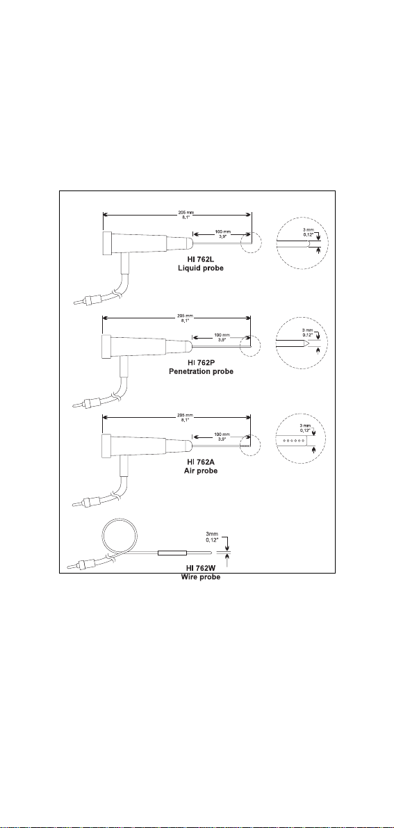
HI 762W Wire probe, without handle (hard-to-reach places)
with 1 m (3.3') cable
HI 762W/10 Wire probe, without handle (hard-to-reach places)
with 10 m (33') cable
HANNA INSTRUMENTS TEMPERATURE PROBES
37
Page 38
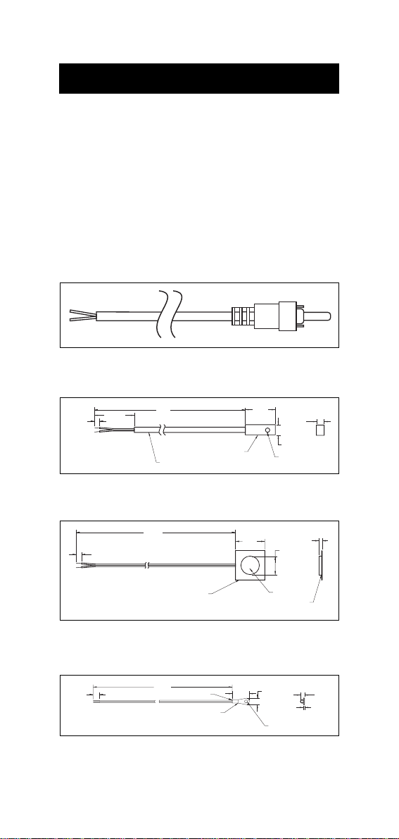
UN-HOUSED NTC SENSORS
It is often necessary to "customize" tests to meet specific criteria. For
this reason, Hanna offers a wide range of NTC thermistor sensors that
can be custom mounted in almost any application. Select the sensor
that matches your requirements, attach it to the Phono style adaptor
and plug it into the meter. You now have a temperature sensor that is
custom built for your application. The following is a list of the NTC
Thermistor sensors available:
HI 76P2-1/P Phono style plug with 1 meter (3 foot) cord (4 pcs)
HI 76S2-1/P NTC Thermistor sensor. Teflon® coated with hole for
mounting (2 pcs)
300mm
6.4mm
0.25"
25.4mm
1.0"
12"
TEFLON TUBING
HI 76S2-2/P NTC Thermistor sensor. Self-adhesive, foam disk for
mounting (4 pcs)
ALUMINUM
HOUSING
19mm
0.75"
4.8mm
0.19"
7.1mm
0.28"
DIA 3.8mm
0.15"
6.4mm
0.25"
38mm
15"
RELEASE
LINER
38mm
1.5"
MYLAR
FOIL
25.4mm
1.00"
FOAM
DISK
3mm
0.12"
HI 76S2-3/P NTC Thermistor sensor. Eye-connector for mounting
(4 pcs)
406mm
6.4mm
0.25"
16"
EPOXY
TIN PLATED Cu
Teflon® is a registered Trademark of "du Pont de Nemours & Co."
38
19mm
0.74"
9.6mm
0.38"
#6 STUD SIZE
1mm
0.04"
5.5mm
0.22"
Page 39
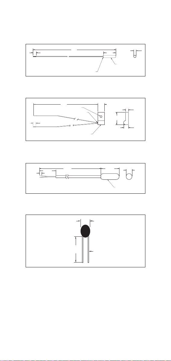
HI 76S2-4/P NTC Thermistor sensor. Molded tip with epoxy seal for
aggressive environments (5 pcs)
6.4mm
0.25"
406mm
16"
EPOXY FILLET
9.6mm
0.38"
2mm
0.08"
MOLDED TIP
HI 76S2-5/P NTC Thermistor sensor. Aluminum tab with mounting
hole (4 pcs)
8mm
0.31"
12.7mm
0.50"
1.6mm
0.06"
4.7mm
0.19"
6.4mm
0.25"
300mm
12"
DIA 3mm
0.12"
EPOXY
ALUMINUM
HOUSING
HI 76S2-6/P NTC Thermistor sensor. PVC encapsulated tip for pro-
tection in aggressive environments (4 pcs)
6.4mm
0.25"
25.4mm
1.0"
300mm
12"
15.8mm
0.625"
MOLDED
PVC TIP
7.1mm
0.28"
HI 76S2-7/P NTC Thermistor sensor. Can be housed and used in any
custom application (10 pcs)
2.4mm
0.095"
38mm
1.50"
LEAD DIA
0.2mm
0.008"
39
Page 40
ACCESSORIES
Calibration Test Plugs see page 35
Temperature Probes see page 36
Un-housed NTC Sensors see page 38
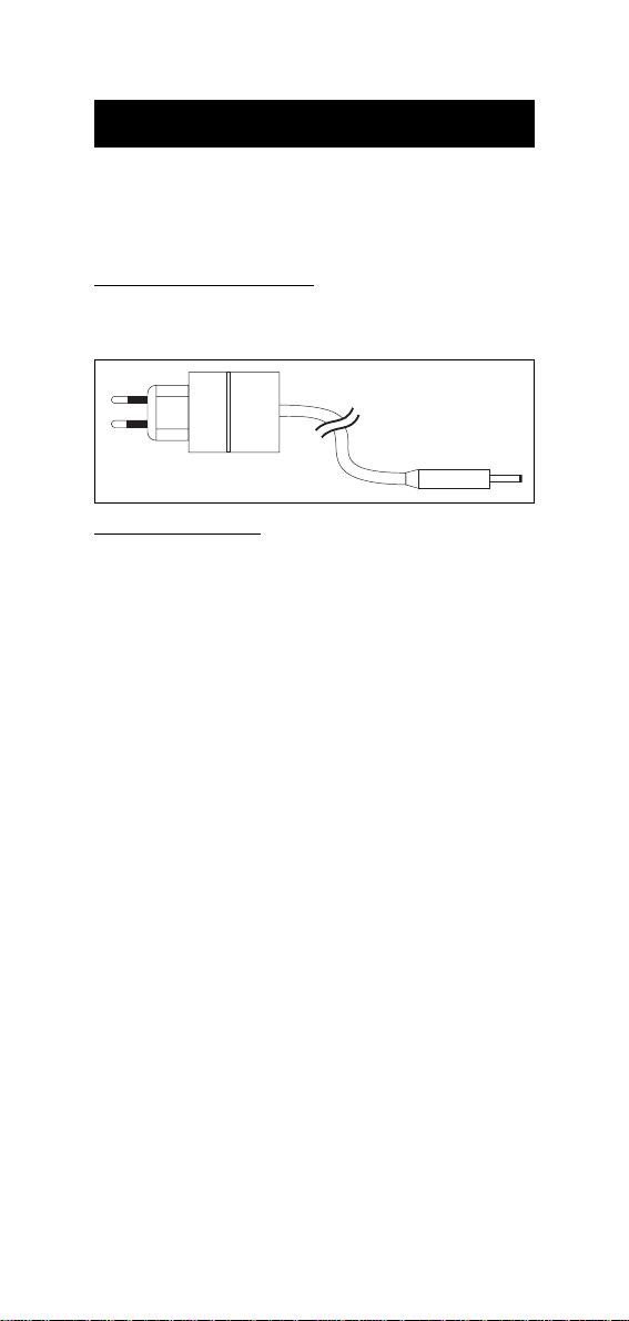
ADAPTERS/TRANSFORMERS
HI 710005 Voltage adapter from 110VAC to 12 VDC
HI 710006 Voltage adapter from 220VAC to 12 VDC
OTHER ACCESSORIES
HI 9200 Infrared Transmitter (for HI 9181 and HI 9184 only)
HI 92000 Windows® software for data transfer to PC (for
HI 9181 and HI 9184 only)
HI 710034 10 Plain Paper Spare Rolls
HI 710035 1 Spare Ink Cartridge
HI 710031 Rugged carrying case
MANPRNFCR2 Instruction manual
Windows® is a registered Trademark of "Microsoft Co."
40
Page 41

WARRANTY
All Hanna Instruments meters are warranted for two years against
defects in workmanship and materials when used for their intended
purpose and maintained according to instructions.
The probes are warranted for a period of six months.
This warranty is limited to repair or replacement free of charge.
Damages due to accidents, misuse, tampering or lack of prescribed
maintenance are not covered.
If service is required, contact the dealer from whom you purchased
the instrument. If under warranty, report the model number, date of
purchase, serial number and the nature of the failure. If the repair is
not covered by the warranty, you will be notified of the charges
incurred.
If the instrument is to be returned to Hanna Instruments, first obtain a
Returned Goods Authorization Number from the Customer Service
department and then send it with shipment costs prepaid. When
shipping any instrument, make sure it is properly packaged for
complete protection.
To validate your warranty, fill out and return the enclosed warranty
card within 14 days from the date of purchase.
All rights are reserved. Reproduction in whole or in part is prohibited
without the written consent of the copyright owner, Hanna
Instruments Inc., 584 Park East Drive, Woonsocket,
Rhode Island, 02895, USA.
Hanna Instruments reserves the right to modify the design, construction and appearance of its products without advance notice.
41
Page 42

OTHER PRODUCTS FROM HANNA
• CALIBRATION AND MAINTENANCE SOLUTIONS
• CHEMICAL TEST KITS
• CHLORINE METERS
• CONDUCTIVITY/TDS METERS
• DISSOLVED OXYGEN METERS
• HYGROMETERS
• ION SPECIFIC METERS (Colorimeters)
• MAGNETIC STIRRERS
• Na/NaCl METERS
• pH/ORP/Na ELECTRODES
• pH METERS
• PROBES (DO, µS/cm, RH, T, TDS)
• PUMPS
• REAGENTS
• SOFTWARE
• THERMOMETERS
• TITRATORS
• TRANSMITTERS
• TURBIDITY METERS
• Wide Range of Accessories
Most Hanna meters are available in the following formats:
• BENCH-TOP METERS
• POCKET-SIZED METERS
• PORTABLE METERS
• PRINTING/LOGGING METERS
• PROCESS METERS (Panel and Wall-mounted)
• WATERPROOF METERS
• METERS FOR FOOD INDUSTRY
For additional information, contact your dealer or the nearest Hanna
Customer Service Center.
You can also e-mail us at tech@hannainst.com.
42
Page 43

CE DECLARATION OF CONFORMITY
DECLARATION OF CONFORMITY
We
Hanna Instruments Srl
V.le delle industrie 12
35010 Ronchi di Villafranca (PD)
ITALY
herewith certify that the thermometers
HI9171 HI9174 HI9181 HI9184 HI9271 HI9274
have been tested and found to be in compliance with the following regulations:
IEC 801-2 Electrostatic Discharge
IEC 801-3 RF Radiated
IEC 801-4 Fast Transient
EN 55022 Radiated, Class B
Date of Issue: 19-02-1996
D.Volpato - Engineering Manager
On behalf of
Hanna Instruments S.r.l.
Recommendations for Users
Before using these products, make sure that they are entirely suitable for the environment
in which they are used.
Operation of these instruments in residential areas could cause unacceptable interference
to radio and TV equipment.
Any variation introduced by the user to the supplied equipment may degrade the
instruments' EMC performance.
Unplug the instruments from power supply before replacing the fuse or making any
electrical connections.
43
Page 44

HANNA LITERATURE
LAB RECORDING WATER ANALYSIS
ENVIROCARE GENERAL CATALOG
These and many others catalogs, handbooks and leaflets are available from Hanna. To receive your free copy, contact your dealer or the
nearest Hanna Customer Service Center.
http://www.hannainst.com
PRINTED IN ITALY
MANPRNFCR2 03/97
 Loading...