

Page 1
Instruction Manual
HI 8510 • HI 8512
HI 8710 • HI 8711
HI 8720
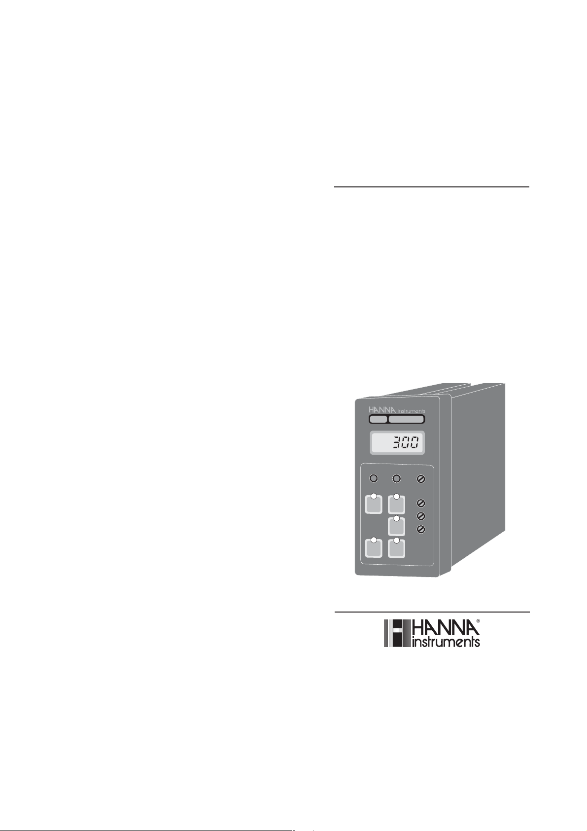
Panel Mounted
pH and ORP
Indicators and Controllers
HI 8720E
ORP
mV
0£
DOSAGE
OXID.
MEA
SURE
0 mV
TEST
www.hannainst.com
REDUC.
SET
ΔAL
500 mV
TEST
SLOPE
ΔAL
COARSE
SET
FINE
1
Page 2

PRELIMINARY EXAMINATION
Dear Customer,
Thank you for choosing a HANNA instruments
product.
Please read this instruction manual carefully
before using the instrument.
If you need additional technical information,
do not hesitate to e-mail us at
tech@hannainst.com.
These instruments are in compliance with the
directives.
TABLE OF CONTENTS
Preliminary Examination ............................. 3
General Description..................................... 3
Available Models ......................................... 4
Mechanical Dimensions .............................. 6
Functional Description HI 8510.................... 7
Functional Description HI 8512.................. 10
Functional Description HI 8710.................. 13
Functional Description HI 8711.................. 16
Functional Description HI 8720.................. 20
Specifications............................................ 24
Initial Preparation ...................................... 27
Operational Guide ..................................... 30
pH Calibration ........................................... 34
pH V alues at V arious T emperature............. 36
pH Diagnostic Tests.................................. 37
ORP Diagnostic Tests............................... 39
LED Indication........................................... 40
T aking Redox Measurements .................... 41
Electrode Maintenance.............................. 43
Suggested Installations ............................. 47
Accessories.............................................. 49
Warranty ................................................... 55
®
Remove the instrument from the packing
material and examine it carefully to make
sure that no damage has occurred during
shipping. If there is any noticeable damage,
immediately notify your dealer.
Each model is supplied complete with
transparent splash-proof front cover, mounting
brackets and instruction manual
Note: Save all packing materials until you
are sure that the instrument functions
correctly. All defective items must be
returned in the original packing materials
together with the supplied accessories.
GENERAL DESCRIPTION
HI 8510 and HI8512 pH and ORP panel-
mounted indicators, and HI 8710, HI 8711
and HI 8720 pH and ORP controllers, are
ideal for process control monitoring in a wide
range of industrial applications.
These instruments have been designed for
easy and fast installation, and are provided
with membrane keypads on the front panel,
large display and autodiagnostic functions.
All connections are made through screw terminals on the rear panel.
Two versions are available for each model, to
accept either a direct input from a pH or ORP
electrode (E version) or from a transmitter
through 4-20mA input (T version).
Moreover, you can choose the output
configuration for connecting a recorder or a
PLC, between 0-20 or 4-20 mA.
2
2£
3
Page 3

AVAILABLE MODELS
HI 8510E020 pH indicator with electrode
input and 0-20 mA recorder
output
HI 8510E420 pH indicator with electrode
input and 4-20 mA recorder
output
HI 8510T020 pH indicator with input from
transmitter and 0-20 mA
recorder output
HI 8510T420 pH indicator with input from
transmitter and 4-20 mA
recorder output
HI 8512E020 ORP indicator with electrode
input and 0-20 mA recorder
output
HI 8512E420 ORP indicator with electrode
input and 4-20 mA recorder
output
HI 8512T020 ORP indicator with input from
transmitter and 0-20 mA
recorder output
HI 8512T420 ORP indicator with input from
transmitter and 4-20 mA
recorder output
HI 8710E020 pH controller with electrode
input and 0-20 mA recorder
output
HI 8710E420 pH controller with electrode
input and 4-20 mA recorder
output
HI 8710T020 pH controller with input from
transmitter and 0-20 mA
recorder output
HI 8710T420 pH controller with input from
transmitter and 4-20 mA
recorder output
HI 8711E020 pH controller with 2 setpoints,
electrode input and 0-20 mA
recorder output
HI 8711E420 pH controller with 2 setpoints,
electrode input and 4-20 mA
recorder output
HI 8711T020 pH controller with 2 setpoints,
input from transmitter and 020 mA recorder output
HI 8711T420 pH controller with 2 setpoints,
input from transmitter and 420 mA recorder output
HI 8720E020 ORP controller with electrode
input and 0-20 mA recorder
output
HI 8720E420 ORP controller with electrode
input and 4-20 mA recorder
output
HI 8720T020 ORP controller with input from
transmitter and 0-20 mA
recorder output
HI 8720T420 ORP controller with input from
transmitter and 4-20 mA
recorder output
4
4£
5
Page 4
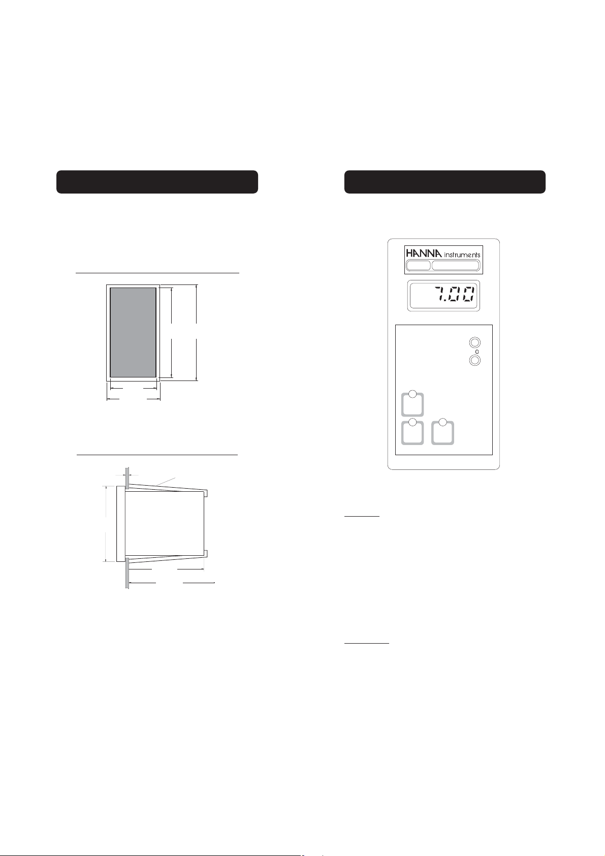
MECHANICAL DIMENSIONS
1
m
"
2.83"
FUNCTIONAL DESCRIPTION HI 8510
The meters are provided with a black anodized
aluminum body, front and back panels in
shockproof ABS plastic and a transparent
splash-proof front cover.
Front view of the panel-mounted unit
141mm
144m
5.55"
5.67
69mm
2.71"
72mm
The dimensions show the cutout size for the
installation.
Side view of the panel-mounted unit
0.25/4mm
0.01/0.160"
ADJUSTABLE
LOCATION
BRACKET
FRONT PANEL
pH
HI 8510E
pH
SENSOR
TEST
pH 7
TEST
pH 4
TEST
SLOPE
Δ
44mm
5.67"
Keypad
SENSOR TEST
To display the mV reading of the electrode and,
therefore, verify its working condition
135mm
5.31"
190mm MIN
7.50"
pH 7 TEST
To verify the internal circuit of the meter in terms
of Offset compensation
Adjustable location brackets (supplied with
the meter) allow the indicator to slide into the
cutout and will hold the unit securely in place.
190 mm (7.50") is the minimum space required to install the indicator with complete
wiring.
6
6£
pH 4 TEST
To verify the amplifier circuit of the meter
Trimmers
ΔΔ
ΔO For Offset calibration
ΔΔ
SLOPE For Slope calibration
7
Page 5
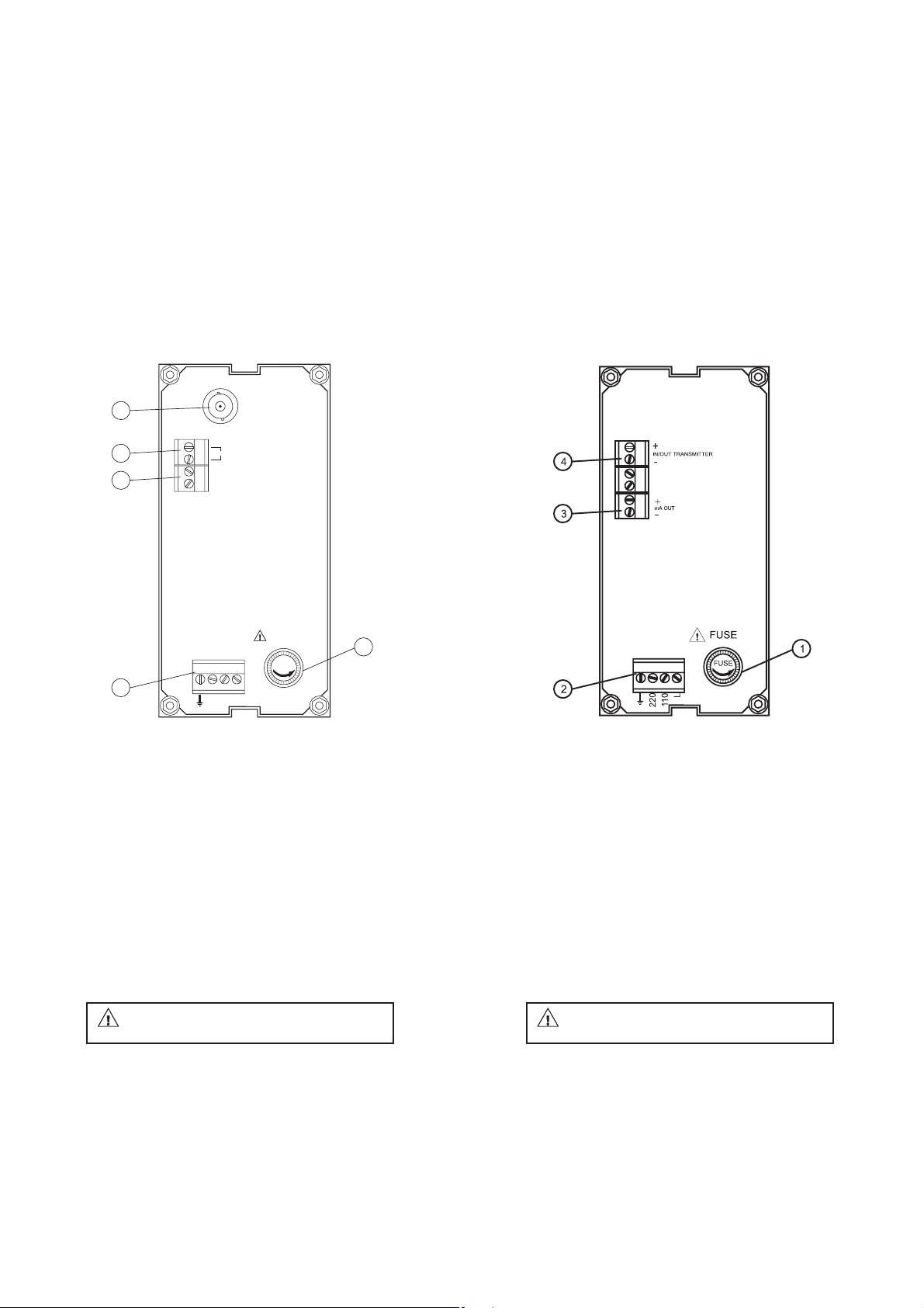
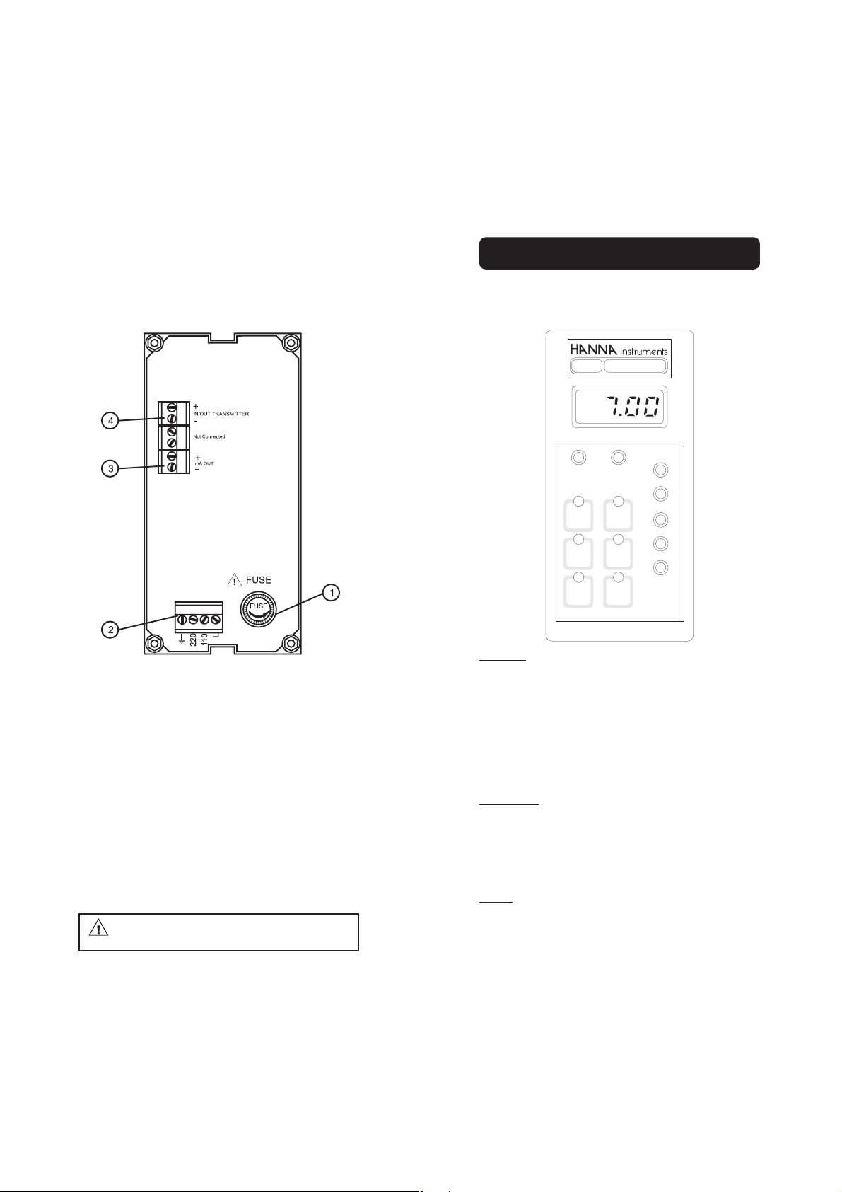
REAR PANEL HI 8510E
5
ELECTRODE
INPUT
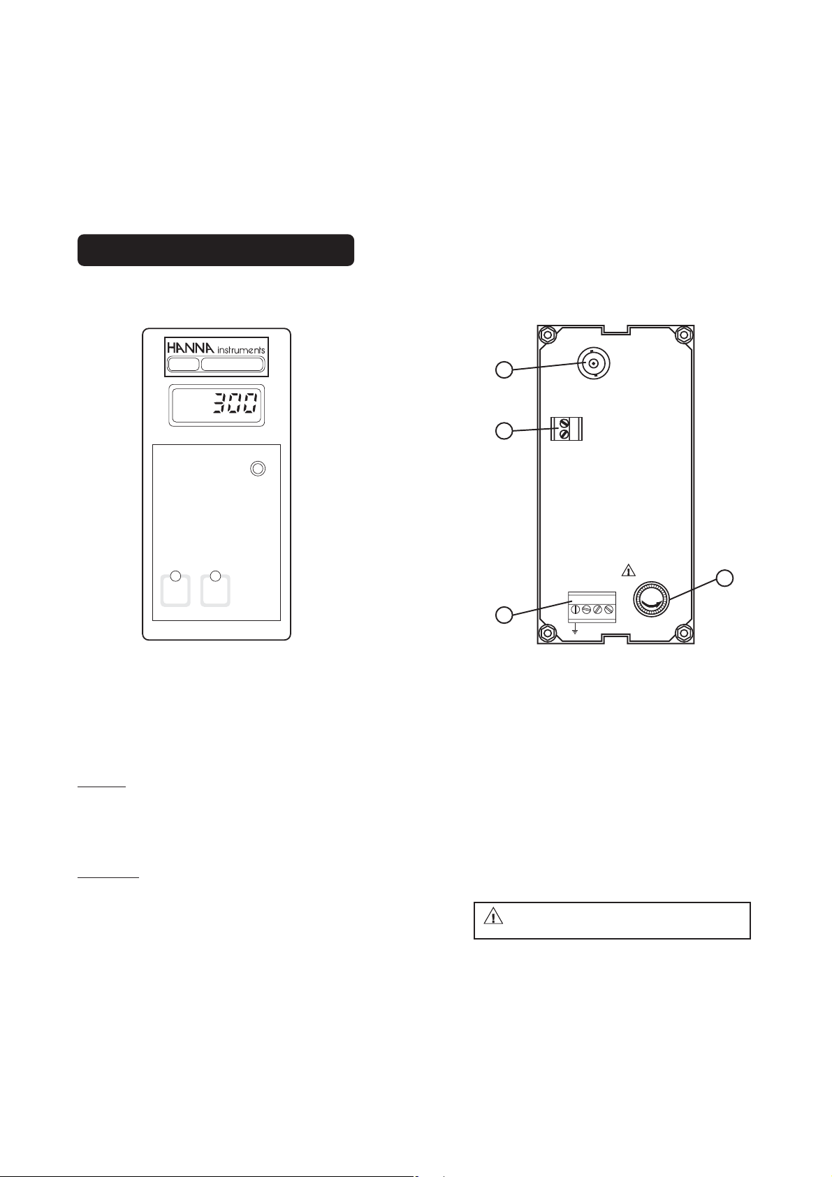
REAR PANEL HI 8510T
4
3
2
PT100
+
mA OUT
-
220
FUSE
FUSE
L
110
1
1. Fuse holder
2. Power supply terminals
3. Recorder output terminals
4. Connections for Pt100 temperature sensor
5. BNC socket for pH electrode
1. Fuse holder
2. Power supply terminals
3. Recorder output terminals
4. Connections to the transmitter
Unplug the instrument from the power
supply before replacing the fuse.
8
8£
Unplug the instrument from the power
supply before replacing the fuse.
9
Page 6
FUNCTIONAL DESCRIPTION HI 8512
FRONT PANEL
HI 8512E
ORP
mV
SLOPE
500 mV
0 mV
TEST
TEST
REAR PANEL HI 8512E
4
+
3
2
mA OUT
-
220
L
110
ELECTRODE
INPUT
FUSE
FUSE
1
Keypad
0 mV TEST To verify the instrument cali-
bration at 0 mV
500 mV TEST To verify the slope at 500 mV
Trimmers
SLOPE For slope calibration
10
10£
1. Fuse holder
2. Power supply terminals
3. Recorder output terminals
4. BNC socket for ORP electrode
Unplug the instrument from the power
supply before replacing the fuse.
11
Page 7
FUNCTIONAL DESCRIPTION HI 8710
REAR PANEL HI 8512T
1. Fuse holder
2. Power supply terminals
3. Recorder output terminals
4. Connections to the transmitter
Unplug the instrument from the power
supply before replacing the fuse.
12
12£
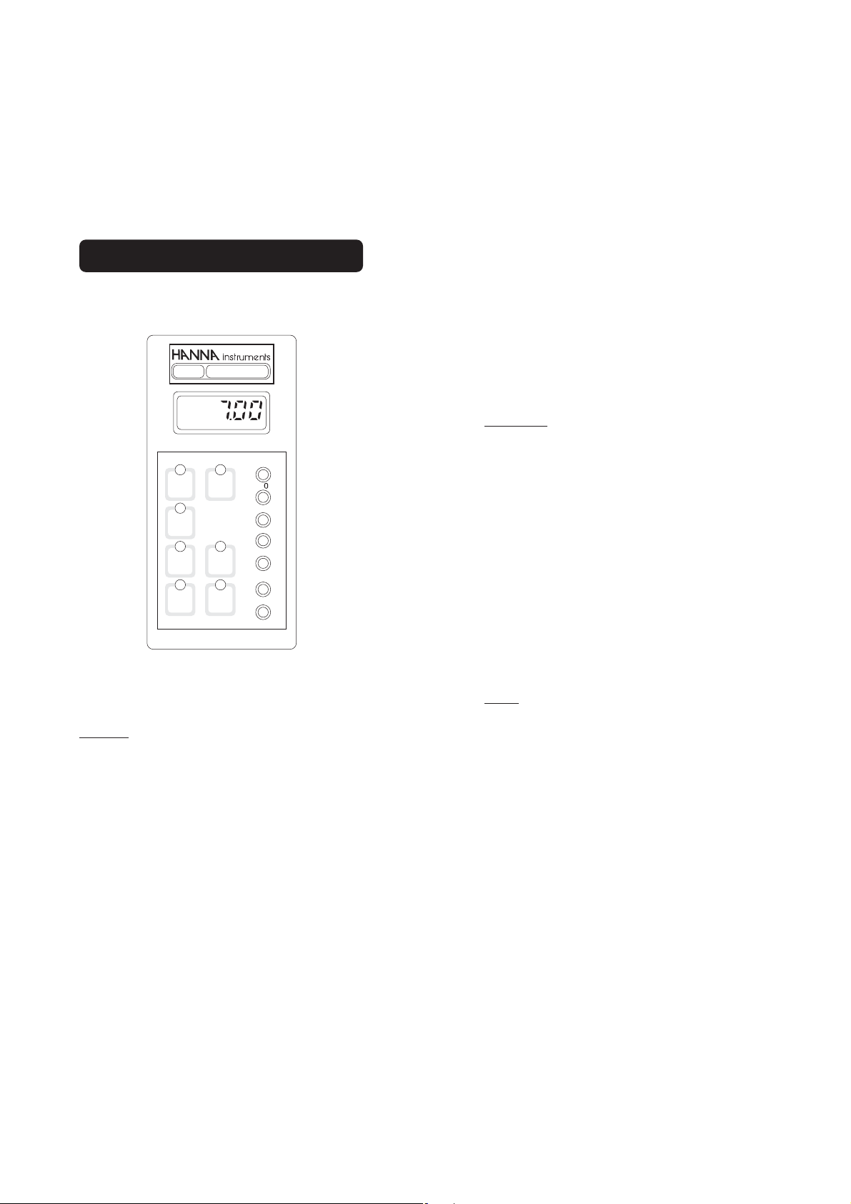
FRONT PANEL
pH
HI 8710E
pH
BASE
SET
ΔAL
pH 4
TEST
13
SLOPE
Δ
0
ΔAL
COARSE
SET
FINE
ACID
MEA
SURE
SENSOR
TEST
pH 7
TEST
Keypad
SET To set the pH dosage limit
MEASURE To enter measurement mode
and to enable diagnostic tests
SENSOR TEST To display electrode mV reading
and verify its working condition
ΔΔ
ΔAL To display & set alarm tolerance
ΔΔ
pH 7 TEST To verify Offset compensation
pH 4 TEST To verify amplifier circuit
Trimmers
ΔΔ
ΔO For Offset calibration
ΔΔ
SLOPE For Slope calibration
ΔΔ
ΔAL To set the alarm tolerance
ΔΔ
SET/COARSE To coarsely adjust the setpoint
SET/FINE To finely adjust the setpoint
LEDs
ACID Show that acid dosage is active
BASE Show that basic dosage is active
ΔΔ
ΔAL (blinking) Indicate an active alarm
ΔΔ
Page 8
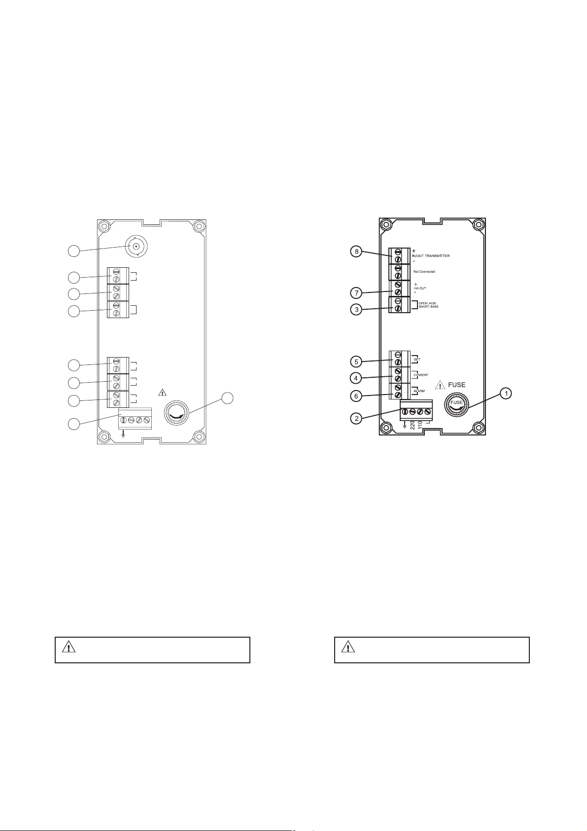
REAR PANEL HI 8710E
9
ELECTRODE
INPUT
REAR PANEL HI 8710T
8
7
3
5
4
6
2
PT100
+
mA OUT
-
OPEN: ACID
SHORT: BASE
SET
CONSENT
ALARM
220
FUSE
FUSE
L
110
1
1. Fuse holder
2. Power supply terminals
3. Acid/Basic dosage selection terminals
4. Red/ox dosage consent terminals
5. Connections for dosing pump
6. Alarm contacts
7. Recorder output contacts
8. Connections for Pt100 temperature sensor
9. BNC socket for pH electrode
1. Fuse holder
2. Power supply terminals
3. Acid/Basic dosage selection terminals
4. Red/ox dosage consent terminals
5. Connections for dosing pump
6. Alarm contacts
7. Recorder output contacts
8. Connections to the transmitter
Unplug the instrument from the power
supply before replacing the fuse.
14
14£
Unplug the instrument from the power
supply before replacing the fuse.
15
Page 9
FUNCTIONAL DESCRIPTION HI 8711
FRONT PANEL
pH
HI 8711E
ΔΔ
ΔAl To display and set the
ΔΔ
alarm tolerance
pH 7 TEST To verify Offset compen-
sation
pH 4 TEST To verify amplifier circuit
pH
SLOPE
ACID
SET
MEA
SURE
SENSOR
TEST
pH 7
TEST
HI 8711E
BASE
SET
ΔAL
pH 4
TEST
Δ
ΔAL
COARSE
ACID SET
FINE
COARSE
BASE SET
FINE
Keypad
ACID SET To set the working point
of acid dosage
BASE SET To set the working point
of basic dosage
MEASURE To enter measurement
mode and to enable
diagnostic tests
SENSOR TEST To display electrode mV
reading and, therefore,
verify its working condition
Trimmers
ΔΔ
ΔO For Offset calibration
ΔΔ
SLOPE For Slope calibration
ΔΔ
ΔAL To set the tolerance of the
ΔΔ
alarm
ACID SET/COARSE To coarsely adjust
acid setpoint
ACID SET/FINE To finely adjust acid
setpoint
BASE SET/COARSE To coarsely adjust
basic setpoint
BASE SET/FINE To finely adjust basic
setpoint
LEDs
ACID SET (Blinking) Show that acid dos-
age is active
BASE SET (Blinking) Show that basic
dosage is active
ΔΔ
ΔAL (Blinking) Indicate active alarm
ΔΔ
16
16£
17
Page 10

REAR PANEL HI 8711E
8
ELECTRODE
INPUT
REAR PANEL HI 8711T
7
6
4
3
5
2
PT100
+
mA OUT
-
BASE
ACID
ALARM
220
FUSE
FUSE
L
110
1
1. Fuse holder
2. Power supply terminals
3. Connections for dosing pump for acid
4. Connections for dosing pump for base
5. Alarm contacts
6. Recorder output contacts
7. Connections for Pt100 temperature sensor
8. BNC socket for pH electrode
1. Fuse holder
2. Power supply terminals
3. Connections for dosing pump for acid
4. Connections for dosing pump for base
5. Alarm contacts
6. Recorder output contacts
7. Connections to the transmitter
Unplug the instrument from the power
supply before replacing the fuse.
18
18£
Unplug the instrument from the power
supply before replacing the fuse.
19
Page 11

FUNCTIONAL DESCRIPTION HI 8720
FRONT PANEL
HI 8720E
ORP
mV
SLOPEDOSAGE
OXID. REDUC.
MEA
SET
SURE
0 mV
TEST
ΔAL
500 mV
TEST
COARSE
ΔAL
SET
FINE
Trimmers
SLOPE For Slope calibration
ΔΔ
ΔAL To display and set the alarm
ΔΔ
tolerance
SET/COARSE To coarsely adjust the
setpoint
SET/FINE To finely adjust the setpoint
LEDs
OXID Show that the oxidant dosage is
active
REDUC Show that the reductant dosage
is active
ΔΔ
ΔAL (blinking) Indicate an active alarm
ΔΔ
Keypad
SET To set the working point of ORP
dosage
MEASURE To enter measurement mode and
to enable diagnostic tests
ΔΔ
ΔAl To display and set the alarm
ΔΔ
tolerance
0 mV TEST To verify the instrument
calibration at 0 mV
500 mV TEST To verify the slope at
500mV
20
20£
21
Page 12

REAR PANEL HI 8720E
8
ELECTRODE
INPUT
REAR PANEL HI 8720T
4
7
3
5
6
2
CONSENT
+
mA OUT
-
OPEN: OXD
SHORT: RDX
SET
ALARM
220
FUSE
FUSE
L
110
1. Fuse holder
2. Power supply terminals
3. Ox/Red dosage selection terminals
4. Ox/red dosage consent terminals
5. Connections for dosing pump
6. Alarm contacts
7. Recorder output contacts
8. BNC socket for ORP electrode
1
1. Fuse holder
2. Power supply terminals
3. Ox/Red dosage selection terminals
4. Ox/red dosage consent terminals
5. Connections for dosing pump
6. Alarm contacts
7. Recorder output contacts
8. Connections to the transmitter
Unplug the instrument from the power
supply before replacing the fuse.
22
22£
Unplug the instrument from the power
supply before replacing the fuse.
23
Page 13

SPECIFICATIONS
HI 8510E HI 8510T
Range 0.00 to 14.00 pH
Resolution 0.01 pH
Accuracy ±0.02 pH ±0.5%
Typical EMC Dev. ±0.1 pH / ±0.2 mA
Installation Category II
Input 1012 Ohm 4 to 20 mA
Calibration Offset: ±2 pH with Δ0 trimmer
Slope: 80 to 110% with slope trimmer
Temperature Fixed or automatic with Pt100
Compensation from 0 to 100°C (32 to 212°F)
Recorder Output 0-20 mA or 4-20 mA (isolated)
Power Supply 115 or 230 Vac; 50/60 Hz
Environment -10 to 50°C (14 to 122°F);
RH max 95% non condensing
Panel Cutout 141 x 69 mm (5.6 x 2.7'')
Weight 1 kg (2.2 lb.)
HI 8512E HI 8512T
Range ±1000 mV
Resolution 1 mV
Accuracy ±5 mV ±0.5%
Typical EMC Dev. ±6 mV / ±0.2 mA
Installation Category II
Input 1012 Ohm 4 to 20 mA
Calibration Slope: 90 to 110% with slope trimmer
Recorder Output 0-20 mA or 4-20 mA (isolated)
Power Supply 115 or 230 Vac; 50/60 Hz
Environment -10 to 50°C (14 to 122°F);
RH max 95% non condensing
Panel Cutout 141 x 69 mm (5.6 x 2.7'')
Weight 1 kg (2.2 lb.)
24
24£
HI 8710E HI 8710T
Range 0.00 to 14.00 pH
Resolution 0.01 pH
Accuracy ±0.02 pH ±0.5%
Typical EMC Dev. ±0.1 pH / ±0.2 mA
Installation Category II
Input 1012 Ohm 4 to 20 mA
Calibration Offset: ±2 pH with Δ0 trimmer
Slope: 80 to 110% with slope trimmer
Temperature Fixed or automatic with Pt100
Compensation from 0 to 100°C (32 to 212°F)
Relays 1 for setpoint and 1 for alarm,
max 2A, 240 V resistive load (isolated)
Recorder Output 0-20 mA or 4-20 mA (isolated)
Power Supply 115 or 230 Vac; 50/60 Hz
Environment -10 to 50°C (14 to 122°F);
RH max 95% non condensing
Panel Cutout 141 x 69 mm (5.6 x 2.7'')
Weight 1 kg (2.2 lb.)
HI 8711E HI 8711T
Range 0.00 to 14.00 pH
Resolution 0.01 pH
Accuracy ±0.02 pH ±0.5%
Typical EMC Dev. ±0.1 pH / ±0.2 mA
Installation Category II
Input 1012 Ohm 4 to 20 mA
Calibration Offset: ±2 pH with Δ0 trimmer
Slope: 80 to 110% with slope trimmer
Temperature Fixed or automatic with Pt100
Compensation from 0 to 100°C (32 to 212°F)
Relays 2 for setpoint and 1 for alarm,
max 2A, 240 V resistive load (isolated)
Recorder Output 0-20 mA or 4-20 mA (isolated)
Power Supply 115 or 230 Vac; 50/60 Hz
Environment -10 to 50°C (14 to 122°F);
RH max 95% non condensing
Panel Cutout 141 x 69 mm (5.6 x 2.7'')
Weight 1 kg (2.2 lb.)
25
Page 14

INITIAL PREPARATION
HI 8720E HI 8720T
Range ±1000 mV
Resolution 1 mV
Accuracy ±5 mV ±0.5%
Typical EMC Dev. ±6 mV / ±0.2 mA
Installation Category II
Input 1012 Ohm 4 to 20 mA
Calibration Slope: 90 to 110% with slope trimmer
Relays 1 for setpoint and 1 for alarm,
max 2A, 240 V resistive load (isolated)
Recorder Output 0-20 mA or 4-20 mA (isolated)
Power Supply 115 or 230 Vac; 50/60 Hz
Environment -10 to 50°C (14 to 122°F);
RH max 95% non condensing
Panel Cutout 141 x 69 mm (5.6 x 2.7'')
Weight 1 kg (2.2 lb.)
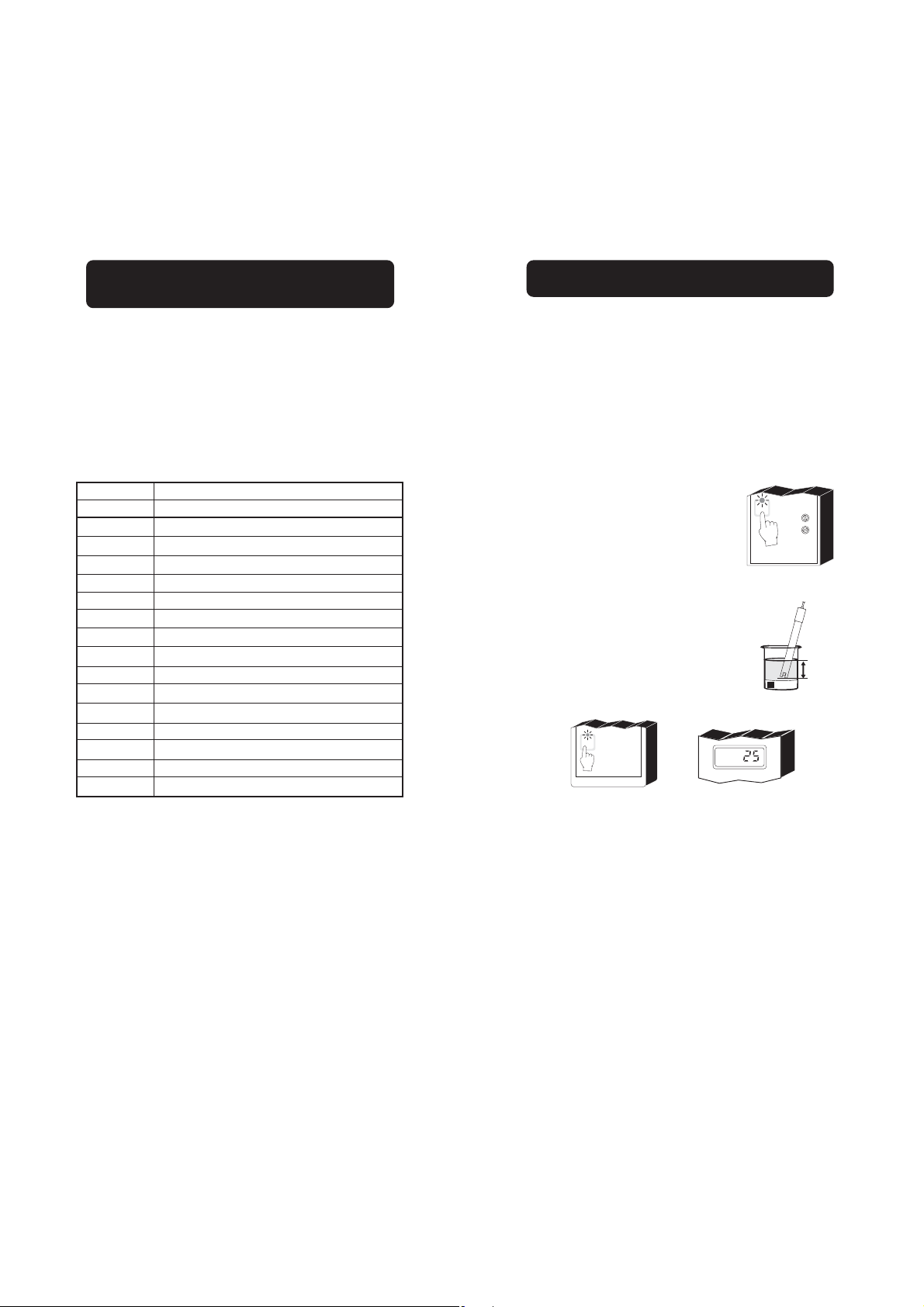
• Connect a 3-wire cable to
the power supply terminal
according to the voltage level
as indicated, and pay particular attention to the correct
live, earth and neutral
connections.
• For E models, connect the
electrode to the BNC plug
on the rear panel.
• For T models, connect the
2 signal wires of the analog
transmitter to the "IN/OUT
TRANSMITTER" terminals,
while paying attention to the
indicated polarity.
• Recorder output terminals:
these contacts are used for
connection to a recorder.
The output can be 0-20 mA
or 4-20 mA depending on
model, and is proportional
to the pH or ORP reading.
• Pt100 terminals: these contacts are used to connect
the Pt100 temperature
sensor for automatic temperature compensation of pH
readings. If temperature compensation is not required,
connect a 110 Ohm/0.25W
resistor across the terminals
(equivalent to a fixed temperature of 25°C/77°F).
FUSE
L
110
220
FUSE
ELECTRODE
INPUT
+
mA OUT
-
PT100
26
26£
27
Page 15

• The HI 8710 models are single dosage
controllers with acid/alkaline selection.
If acid dosage is needed
(e.g. in chromium VI
reduction), leave open the
ACID/BASE selection
OPEN: ACID
SHORT: BASE
terminals (see picture), while
for alkaline dosage (e.g. in
cyanide oxidation), make a
short circuit across the
ACID/BASE selection
OPEN: ACID
SHORT: BASE
terminals with a jumper wire.
• The HI 8720 models are single dosage
controllers with oxidant/reductant selection.
If oxidant dosage is needed
(e.g. in cyanide oxidation),
leave open the OX/RED
selection terminals (see
OPEN: OXD
SHORT: RDX
picture), while for reductant
dosage (e.g. in chromium
VI reduction), make a short
circuit across the OX/RED
selection terminals with a
OPEN: OXD
SHORT: RDX
jumper wire.
• Set contacts (HI 8710 and HI 8720): these
contacts (max. 2A, 240 V)
are used to connect the
dosing pump, and act only
SET
FUSE
FUSE
as a switch for the power
to the drive.
• Acid contacts (HI 8711):
these contacts are used to
connect the dosing pump
for acid, and act as a switch
ACID
FUSE
FUSE
for the power to the drive.
• Base contact (HI 8711):
these contacts are used to
connect the dosing pump
for base, and act as a
BASE
FUSE
FUSE
switch for the power to the
drive.
• Consent contacts (HI 8710 and HI 8720):
these contacts (max. 2A, 240V) are used
for reduction and oxidation reactions when
the pH controller works in conjunction with
an ORP controller and vice versa.
In these applications, the consent contacts
of both meters are connected together to
link the ORP and pH controllers, so that
ORP dosage will occur only if the actual
pH value is correct. This feature avoids
overdosages which may lead to undesirable
pollution.
For HI 8710, the "Consent" contacts can
be left open if the instrument is used
independently as pH controller only.
For HI 8720, the "Consent" contacts should
be shorted if the instrument is used independently as ORP controller only.
• Alarm contacts (HI 8710,
HI 8711 and HI 8720): if the
ALARM
pH or ORP measurement is
not within the set value
FUSE
FUSE
tolerance, the alarm contact
is closed.
Note: All external cables connected to the rear
panel should be ended with cable lugs.
28
28£
29
Page 16

OPERATIONAL GUIDE
ΔAL
ΔAL
All instrument settings are made via front
panel keys and trimmers.
When each key is pressed, the corresponding
LED lights up to show the operating function.
If using a model with input from electrode,
make sure that the meter is calibrated before
starting any operation (see "Calibration"
section for details).
Using a small screwdriver adjust the ACID
SET COARSE and FINE trimmers to display
the desired acid set value.
ACID
BASE
SET
SET
COARSE
ACID SET
FINE
pH
To set the working point for alkaline dosage,
press the BASE SET key and the display will
show the set value for base dosage.
SET POINTS (HI 8710 and HI 8720)
To set the working point for pH or ORP
dosage, press SET and the display will show
the set value.
SET
COARSE
SET
FINE
pH
Using a small screwdriver adjust the COARSE
and FINE trimmers to display the desired set
value.
SET
COARSE
SET
FINE
pH
SET POINTS (HI 8711)
To set the working point for acid dosage,
press the ACID SET key and the display will
show the set value for acid dosage.
ACID
BASE
SET
SET
COARSE
BASE SET
FINE
pH
Using a small screwdriver adjust the BASE
SET COARSE and FINE trimmers to display
the desired base set value.
ACID
BASE
SET
SET
pH
BASE SET
COARSE
FINE
ALARMS (HI 8710, HI 8711 and HI 8720)
To set the alarm tolerance, press ΔAL key
and the display will show the current value.
pH
ACID
BASE
SET
SET
COARSE
ACID SET
FINE
30
pH
30£
Using a small screwdriver adjust the ΔAL
trimmer to display the desired tolerance.
31
Page 17

ΔAL
ΔAL
pH
the ACID LED lights up, while
during alkaline dosage, the
BASE LED turns on (HI 8710
only).
ACID BASE
MEA
SURE
SLOPEDOSAGE
ΔAL
SET
COARSE
SET
FINE
When acid dosage is active,
Examples:
For HI 8710, if the set value is pH 3 and the
ΔAlarm is 1.5 pH, the instrument generates
an alarm every time the pH reading is higher
than 4.5 pH or lower than 1.5pH.
For HI 8711, if the set values are pH 7 and
pH 8, and the Δ Alarm is 1.5 pH, the instrument generates an alarm every time the pH
reading is higher than 9.5 pH or lower than
5.5 pH.
For HI 8720, if the set value is 300 mV and the
ΔAlarm is 100 mV, the instrument generates an
alarm every time the ORP reading is higher than
400 mV or lower than 200 mV.
MEASUREMENTS
After setting the pH (or ORP)
and alarm (if available)
thresholds, immerse the elec-
MEA
SURE
COARSE
SET
FINE
trode in the solution to be
tested and press MEASURE.
The actual pH or ORP value of the test solution is displayed.
When oxidant dosage is active,
the OXID LED lights up, while
during reductant dosage, the
REDUC LED turns on (HI 8720
only).
OXID. REDUC.
MEA
SURE
SLOPEDOSAGE
ΔAL
SET
COARSE
SET
FINE
pH
32
mV
32£
33
Page 18

pH CALIBRATION
Make sure that the instrument
is in measurement mode
(MEASURE LED is on) before
proceeding with calibration.
Rinse pH electrode and thermometer probe
thoroughly with water, then immerse them in
pH4.01 (HI 7004) or pH 10.01 (HI 7010) buffer
solution.
MEA
SURE
COARSE
SET
FINE
Note: For accurate readings, use pH 4.01 if
you are going to measure acid samples
or pH 10.01 for alkaline measurements.
Measure the temperature of
the calibration buffer with a
°C
ChecktempC or another
accurate thermometer.
Remove the protective cap
from the electrode, rinse and
HI 7007
(1½")
4 cm
immerse in pH 7.01 solution
(HI 7007).
Note: The electrode should be
submerged at least 4
°C
cm (1½") into the solution. The thermometer
should be located as
close as possible to the
HI 7004
(1½")
4 cm
pH electrode.
Shake briefly and wait one minute before
adjusting the Δ0 trimmer to display the buffer
solution value, i.e. "pH 7.01" at 25°C (77°F).
DOSAGE
SLOPE
ACID BASE
ΔO
MEA
SET
SURE
COARSE
SET
FINE
pH
Shake briefly and wait one minute before
adjusting the slope trimmer to display the ph
value of the buffer solution, i.e. pH 4.01 (or
10.01) at 25°C (77°F).
DOSAGE
SLOPE
ACID BASE
ΔO
MEA
SET
SURE
COARSE
SET
FINE
pH
If the buffer solution temperature is different
from 25°C (77°F), refer to the "pH vs.
temperaturare" chart on page 36 for the appropriate pH value at the noted temperature.
The calibration is now complete and the instrument is ready for use.
Note: If a Pt100 temperature sensor is used,
immerse it into the buffer solutions
during calibration.
If the buffer solution temperature is different
from 25°C (77°F), refer to the "pH vs.
temperaturare" chart on page 36 for the appropriate pH value at the noted temperature.
34
34£
35
Page 19
pH VALUES AT VARIOUS
SENSOR
TEST
TEMPERATURE
pH DIAGNOSTIC TESTS
Temperature has an effect on the pH. The
calibration buffer solutions are affected by
temperature changes to a lesser degree than
normal solutions.
Please refer to the following chart to perform
the pH calibration:
TEMP pH VALUE
°C °F 4.01 6.86 7.01 9.18 10.01
0
32
4.01
10
15
20
25
30
35
40
45
50
55
60
65
70
6.98
5
41
4.00
6.95
50
4.00
6.92
59
4.00
6.90
68
4.00
6.88
77
4.01
6.86
86
4.02
6.85
95
4.03
6.84
104
4.04
6.84
113
4.05
6.83
122
4.06
6.83
131
4.07
6.84
140
4.09
6.84
149
4.11
6.85
158
4.12
6.85
7.13
7.10
7.07
7.04
7.03
7.01
7.00
6.99
6.98
6.98
6.98
6.98
6.98
6.99
6.99
9.46
9.39
9.33
9.27
9.22
9.18
9.14
9.10
9.07
9.04
9.01
8.99
8.97
8.95
8.93
10.32
10.24
10.18
10.12
10.06
10.01
9.96
9.92
9.88
9.85
9.82
9.79
9.77
9.76
9.75
HI 8510, HI 8710 and HI 8711 are provided
with autodiagnostic functions that allow to
check and troubleshoot any malfunctioning.
The functions are made via front panel keys
to isolate the cause of malfunction whether it
is due to pH electrode contamination, internal
offset circuit or amplifier circuit.
Follow the procedure described below.
First press the MEASURE
key, then one of the following
keys.
MEA
SURE
COARSE
SET
FINE
A) Sensor Test
Immerse the electrode in
pH7.01 buffer solution
(HI 7007), press SENSOR
HI 7007
(1½")
4 cm
TEST key and the display
shows the mV response
of the electrode.
mV
If the electrode is in good working condition, the value should be within ±30 mV.
For instance, if the buffer temperature is 25°C
(77°F), calibrate to read on the display pH
4.01 or 7.01 or 10.01.
If the buffer temperature is 20°C, calibrate to
read on the display pH 4.00 or 7.03 or 10.06.
If the buffer temperature is 50°C, calibrate to
A value between 30 and 60 mV or -60 and
-30 mV, indicates some contamination of
the electrode.
If the value is higher than 60mV or lower
than -60 mV, the contamination is too
high and the electrode should be replaced.
read on the display pH 4.06 or 6.98 or 9.82.
36
36£
37
Page 20

B) Internal Offset Circuit Test
Press the pH7 TEST key and the display
should show a value within 7±1 pH, to
verify the internal circuit of the meter in
terms of the offset compensation.
pH 7
TEST
pH
ORP DIAGNOSTIC TESTS
HI 8512 and HI 8720 are ORP controllers
provided with autodiagnostic functions that
allow to check and troubleshoot any
malfunctioning.
The functions are made via front panel keys
to isolate the cause of malfunction.
C) Amplifier Circuit Test
Press the pH4 TEST key and the display
should show a value within the 3.30 to
4.30 pH range, to verify the amplifier circuit
of the meter.
pH 4
TEST
pH
For HI 8720 only, press
MEASURE key before
proceeding with the following
tests.
A) 0 mV Test
Press the 0 mV TEST
key and the display
should show a value of
0±10 mV, to verify the
"zero" calibration of the
instrument.
B) 500 mV Test
Press the 500 mV TEST
key and the display should
show a value of 500±20
mV, to verify the slope
at 500 mV.
MEA
SURE
COARSE
SET
FINE
mV
500 mV
0 mV
TEST
TEST
mV
500 mV
0 mV
TEST
TEST
38
38£
39
Page 21

LED INDICATION
TAKING REDOX MEASUREMENTS
All LEDs above the keys indicate the state of
each function, whether it is active or the
display is indicating the mode.
For HI 8711 only
Each LED can be in one of the following
states:
A)Light on The mode is displayed
on the LCD but is not
active, e.g. the alarm
setpoint is displayed but
the alarm contact is
open.
B)Light blinking 25% on, 75% off
The mode is not displayed but it is active,
e.g. the alarm contact
is closed but the alarm
setpoint is not displayed.
C)Light blinking 75% on, 25% off
The mode is active and
being displayed.
D)Light off The function is neither
active nor displayed.
40
40£
Redox measurements allow the quantification of the solution oxidizing/reducing power,
and are commonly expressed in mV.
Oxidation may be defined as the process
during which a molecule (or an ion) loses
electrons and reduction as the process by
which electrons are gained.
Oxidation is always coupled together with
reduction, so that as one element gets oxidized, the other is automatically reduced,
therefore the term oxidation-reduction is frequently used.
Redox potentials are measured by an electrode capable of absorbing or releasing electrons without causing any chemical reaction.
The most common ORP electrodes are
provided with gold or platinum surfaces; gold
features a higher resistance than platinum in
conditions of strong oxidation, while platinum
is preferred for measuring oxidizing solutions
containing halides, and for general purposes.
When a platinum electrode is immersed in an
oxidizing solution, a monomolecular layer of
oxygen is developed on its surface. This layer
does not prevent the electrode from functioning, but it increases the response time. The
opposite effect is obtained when the platinum
surface absorbs hydrogen in the presence of
reducing mediums. This phenomenon is rough
on the electrode.
To make correct redox measurements, it is
necessary that the surface of the electrode is
clean and smooth, and that a preventive
treatment is performed.
Because the Pt/PtO system depends on the
solution pH level, the electrode pre-treatment
may be determined by the pH and the redox
potential of the solution to be measured.
41
Page 22

Generally, if the ORP (mV) reading corresponding to the pH solution value is higher
than the value in the table below, an oxidizing
pre-treatment is necessary; otherwise a reducing pre-treatment is necessary:
pH m V pH m V pH mV pH m V p H mV
0 990 1 920 2 860 3 800 4 740
5 680 6 640 7 580 8 520 9 460
10 400 11 340 12 280 13 220 14 16 0
Reducing pre-treatment: immerse the electrode for some minutes in HI 7091 solution.
Oxidizing pre-treatment: immerse the electrode for some minutes in HI 7092 solution.
If no pre-treatment is performed, the electrode will have long response times.
If working with refillable electrodes, always
check the internal electrolyte level and refillwith
HI 7071 solution, if necessary (the level must
be at least 2.5 cm below the filling hole).
If measurements are taken in solutions containing sulfides or proteins, the cleaning of
the electrode junction must be performed (see
"Cleaning Procedure" section for details).
To check the correct functioning of the ORP
electrode, immerse it into HI 7020 test
solution and verify that the reading is within
200 and 275 mV.
After the test, rinse the electrode thoroughly
with water and proceed with the oxidizing or
reducing pre-treatment before taking any
measurement.
When not in use, the electrode tip should be
kept moist and far from any type of mechanical stress which might cause damage. For
this reason, it is reccommended to store the
electrode with a few drops of HI 70300 storage
solution in the supplied protective cap.
ELECTRODE MAINTENANCE
Reference
Filling Hole
Reference
Filling Hole
Fill Hole
Screw
Sensitive
Wire
Reference
Wire
Reference
Junction
Glass
Bulb
Reference
Wire
Reference
Junction
Platinum or
Gold tip
Plastic Body
pH Electrode
Reference
Plastic Body
ORP Electrode
Glass Body
pH Electrode
Wire
Glass Body
ORP Electrode
Reference
Wire
Sensitive
Wire
Reference
Junction
Glass
Bulb
Reference
Junction
Platinum or
Gold tip
PREPARATION
Remove the protective cap.
DO NOT BE ALARMED IF ANY SALT DE-
POSITS ARE PRESENT. This is normal with
electrodes and they will disappear when rinsed
with water.
During transport tiny air bubbles may form inside the glass bulb, and the electrode cannot
function properly under these conditions. Remove
the bubbles by "shaking down" the electrode
as you would do with a glass thermometer.
42
42£
43
Page 23

If the bulb and/or junction are dry, soak the
electrode in HI 70300 storage solution for at
least one hour.
For refillable electrodes:
If the internal electrolyte solution is more than
1cm (½") below the filling hole, add HI 7082
solution (3.5M KCl) for double junction
electrodes or HI 7071 (3.5M KCl+AgCl) for
single junction electrodes.
For a faster response unscrew the filling hole
screw during measurements.
For AmpHel® electrodes:
If the electrode does not respond to pH
changes, the battery is run down and the
electrode should be replaced.
MEASUREMENT
Rinse the electrode tip with distilled water.
Immerse the electrode tip (4 cm) in the sample
and stir gently for approximately 30 seconds.
For a faster response and to avoid cross
contaminations, before taking measurements,
rinse the electrode tip with some solution to
be tested.
STORAGE
To minimize clogging and assure a quick
response time, the electrode glass bulb and
junction should be kept moist at any time.
Store the electrode with a few drops of
HI70300 storage solution in the protective
cap (in its absence, use HI 7071 electrolyte
for single junction, or HI 7082 for double junction electrodes).
Follow the above "Preparation Procedure" before taking measurements.
Note: NEVER STORE THE ELECTRODE IN
DISTILLED WATER OR DRY.
PERIODIC MAINTENANCE
Inspect electrode and cable. The cable used
for the connection to the meter must be intact
and there must be no points of broken insulation on the cable or cracks on the electrode
stem or bulb.
Connectors must be perfectly clean and dry.
If any scratches or cracks are noted, replace
the electrode.
Rinse off any salt deposits with water.
For refillable electrodes:
Refill the electrode with fresh electrolyte
solution (HI 7071 for single junction electrodes
or HI 7082 for double junction). Allow the
electrode to stand upright for 1 hour.
Follow the above "Storage Procedure".
CLEANING PROCEDURE
General Soak in HI 7061 general cleaning
solution for approximately 1 hour.
Removal of films, dirt or deposits on the membrane/junction:
Protein Soak in Hanna HI 7073 protein
cleaning solution for 15 minutes.
Inorganic Soak in Hanna HI 7074 inorganic
cleaning solution for 15 minutes.
Oil/grease Rinse with Hanna HI 7077 oil &
fat cleaning solution.
IMPORTANT: After performing any of the
cleaning procedures, rinse the electrode thoroughly with distilled water, drain and refill the
reference chamber with fresh electrolyte, (not
necessary for gel-filled electrodes) and soak
the electrode in HI 70300 storage solution for
at least 1 hour before taking measurements.
AmpHel® is a registered Trademark of "Hanna Instruments"
44
44£
45
Page 24
TROUBLESHOOTING
Evaluate your electrode performance based
on the following:
• Noise (readings fluctuate up and down)
could be due to:
- Clogged/Dirty Junction: refer to the
above "Cleaning Procedure"
- Loss of shielding due to low electrolyte
level (in refillable electrodes only): refill
with HI 7071 solution for single junction
or HI 7082 for double junction electrodes
• Dry Membrane/Junction: soak in HI70300
storage solution for at least 1 hour
• Drifting: soak the electrode tip in warm
HI7082 solution for one hour and rinse the
tip with distilled water; refill with fresh
electrolyte (HI 7071 for single junction and
HI 7082 for double junction electrodes)
• Low Slope: refer to the above "Cleaning
Procedure"
• No Slope: check the electrode for cracks
in glass stem or bulb (replace the electrode if cracks are found)
• Slow Response/Excessive Drift: soak the
tip in HI 7061 solution for 30 minutes,
rinse thoroughly in distilled water and then
follow the above "Cleaning Procedure"
• For ORP Electrodes: polish the metal tip
with a light abrasive paper (pay attention
not to scratch the surface) and rinse
thoroughly with water
SUGGESTED INSTALLATIONS
SHORT DISTANCE, INDOOR INSTALLATION
Due to the low current involved, a very high
grade of insulation is required.
A dry environment is needed in order to obtain a insulation level not lower than 1012Ω.
This type of connection is very delicate and
requires constant attention to maintain proper
operating conditions.
Conventional electrodes should be used in
indoor applications only, with a cable not
longer than 10 m (33').
MAXIMUM 10 METERS
DRY ENVIRONMENT
LESS THAN 80%
RELATIVE HUMIDITY
pH METER
pH-ORP METER
WITH CONVENTIONAL ELECTRODES
MEASUREMENTS CAN BE
TAKEN FROM DISTANCES UP TO
10 METERS (33 FEET)
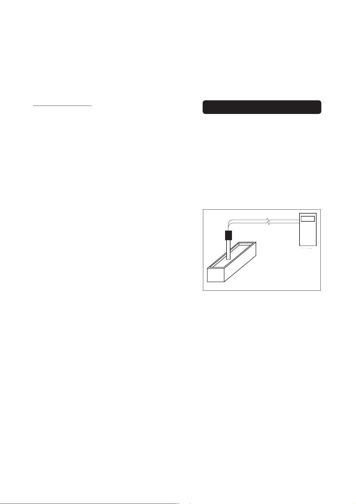
MEDIUM DISTANCE, INDOOR/OUTDOOR
INSTALLATION
When an outdoor installation is required, to
obtain accurate readings at distances from
10 to 50 m (33-165'), it is necessary to
install a transmitter.
Since the introduction of AmpHel® electrodes,
these distances are no longer a problem.
You can now connect the meter directly to
an AmpHel® electrode, saving the cost of a
transmitter or expensive coaxial cable.
The standard cable length for AmpHel
electrodes is 5 m (16.5'). Additional lengths
®
46
46£
47
Page 25

of regular cable up to 50 m (165'), can be
installed without special connectors.
AmpHel® electrodes feature a built-in a microamplifier to boost the signal, drastically reducing susceptibility to noise and drift.
The sealed electrode body can stand a moisture up to 100% RH without any effect on the
signal.
MAXIMUM 50 METERS
WET ENVIRONMENT
RELATIVE HUMIDITY UP TO 100%
pH-ORP METER
pH METER
WITH AN AmpHel ELECTRODE
MEASUREMENTS CAN BE
TAKEN FROM DISTANCES UP TO
®
50 METERS (165 FEET)
LONG DISTANCE INSTALLATIONS, ISOLATED
OUTPUT FOR PC INTERFACE
If the needed installation distance is greater
than 50 m (165'), it is necessary the use of a
transmitter.
HANNA instruments® offers a full line of pH
and ORP transmitters with or without display.
3m
RELATIVE HUMIDITY UP TO 100%
AmpHel® is a registered Trademark of "Hanna Instruments"
MAXIMUM 300 METERS
WET ENVIRONMENT
WITH A pH TRANSMITTER AND
TAKEN FROM DISTANCES UP TO
48
pH-ORP METER
pH METER
CONVENTIONAL ELECTRODE
MEASUREMENTS CAN BE
300 METERS (1000 FEET)
48£
ACCESSORIES
pH CALIBRATION SOLUTIONS
HI 7004M pH 4.01 buffer solution, 230 mL
HI 7004L pH 4.01 buffer solution, 500 mL
HI 7006M pH 6.86 buffer solution, 230 mL
HI 7006L pH 6.86 buffer solution, 500 mL
HI 7007M pH 7.01 buffer solution, 230 mL
HI 7007L pH 7.01 buffer solution, 500 mL
HI 7009M pH 9.18 buffer solution, 230 mL
HI 7009L pH 9.18 buffer solution, 500 mL
HI 7010M pH 10.01 buffer solution, 230mL
HI 7010L pH 10.01 buffer solution, 500 mL
ORP SOLUTIONS
HI 7020M ORP test solution @200/275 mV,
230 mL bottle
HI 7020L ORP test solution @200/275 mV,
500 mL bottle
HI 7091M Pre-treatment reducing solution,
230 mL bottle
HI 7091L Pre-treatment reducing solution,
500 mL bottle
HI 7092M Pre-treatment oxidizing solution,
230 mL bottle
HI 7092L Pre-treatment oxidizing solution,
500 mL bottle
ELECTRODE MAINTENANCE SOLUTIONS
HI 70300M Storage solution, 230 mL bottle
HI 70300L Storage solution, 500 mL bottle
HI 7061M General cleaning, 230 mL bottle
HI 7061L General cleaning, 500 mL bottle
HI 7073M Protein cleaning solution, 230 mL
HI 7073L Protein cleaning solution, 500 mL
HI 7074M Inorganic cleaning, 230 mL
HI 7074L Inorganic cleaning, 500 mL
HI 7077M Oil & fat cleaning, 230 mL
HI 7077L Oil & fat cleaning,500 mL
HI 7071 3.5M KCl+AgCl electrolyte
solution (4 x 50 mL)
HI 7072 1M KNO3 electrolyte (4 x 50 mL)
HI 7082 3.5M KCl electrolyte solution (4
x 50 mL)
49
Page 26

PG13.5 THREAD
110mm30mm
D
3/4 x 16 UNF
D
3/4 x 16 UNF
D
DIA 9.5mm
110mm
D
3/4 x 16 UNF
pH ELECTRODES
PG13.5 THREAD
m
110mm30mm
DIA 9.5mm
3
110mm
D
M13 x 1.5
A
6
m
mm
mm
PG13.5 THREAD
m
110mm30mm
D
3/4 x 16 UNF
M13 x 1.5
A
6
m
mm
mm
150mm
DIA 16.5mm
M13 x 1.5
A
6
m
mm
mm
HI 1090T Screwcap PG13.5 connector,
double junction, glass body
φ 12mm φ 9.5m
HI 1110S Screw connector, single junction,
glass body
HI 1130B/3 BNC connector, 3 m (9.9') cable,
single junction, glass body
/4 x 16 UNF
DI
IA 20.5mm
1
m
25
7
HI 1110S HI 1130B/3
38.5mm
DIA 12mm
HI 1110T Screwcap PG13.5 connector,
double junction, glass body
φ 12mm φ 9.5m
5mm
DIA 7.6mm
DI
1
m
25
7
HI 1115S HI 1135B/3
25mm
DIA 12mm
HI 1210T Screwcap PG13.5 connector,
double junction, plastic body
φ 12mm
HI 1910B BNC connector, 1 m (3.3') cable,
double junction, plastic body, builtin amplifier
DIA 12mm
IA 20.5mm
38.5mm
110mm
HI 1911B BNC connector, 1 m (3.3') cable,
double junction, plastic body, builtin amplifier
DIA 12mm
HI 1114S Screw connector, double junction,
plastic body
HI 1134B/3 BNC connector, 3 m (9.9') cable,
double junction plastic body
DIA 12mm
DI
1
IA 20.5mm
m
25
7
HI 1114S HI 1134B/3
38.5mm
110mm
HI 1115S Screw connector, single junction,
glass body
HI 1135B/3 BNC connector, 3 m (9.9') cable,
single junction, glass body
50
50£
IA 20.5mm
38.5mm
110mm
HI 1912B BNC connector, 1 m (3.3') cable,
double junction, plastic body, builtin amplifier
3/4 x 16 UNF
IA 20.5mm
38.5mm
DIA 12mm
HI 1912B/5 BNC connector, 5 m (16.5') cable,
double junction, plastic body, builtin amplifier
DIA 12mm
IA 20.5mm
38.5mm
51
110mm
Page 27

PG13.5 THREAD
110mm30mm
D
3/4 x 16 UNF
M13 x 1.5
A
6
m
mm
mm
3/4 x 16 UNF
110mm
D
3/4 x 16 UNF
110mm
M13 x 1.5
DIA
16
mm
7
mm
25
mm
3/4 x 16 UNF
110mm
HI 2114B/5 BNC connector, 5 m (16.5') cable,
D
3/4 x 16 UNF
D
3/4 x 16 UNF
D
3/4 x 16 UNF
110mm
M13 x 1.5
A
6
m
mm
mm
PG13.5 THREAD
m
110mm30mm
DIA 16.5mm
M13 x 1.5
DIA
16
mm
7
mm
25
mm
double junction, plastic body
DIA 12mm
IA 20.5mm
HI 3210T Screwcap PG13.5 connector, Pt,
plastic body
φ 12mm
38.5mm
110mm
HI 2910B/5 BNC connector, 5 m (16.5') cable,
double junction, plastic body, builtin amplifier
DIA 12mm
IA 20.5mm
38.5mm
110mm
ORP ELECTRODES
HI 2930B/5 BNC connector, 5 m (16.5') cable,
Pt, plastic body, built-in amplifier
HI 3110S Screw connector, Pt, glass body
HI 3130B/3 BNC connector, 3 m (9.9') cable,
Pt, glass body
DIA 12mm
DI
IA 20.5mm
1
m
25
7
HI 3110S HI 3130B/3
38.5mm
HI 3110T Screwcap PG13.5 connector, Pt,
glass body
φ 12mm φ 1m
HI 3115S Screw-type connector, side-arm,
Pt, glass body
HI 3135B/3 BNC connector, 3 m (9.9') cable,
side-arm, Pt, glass body
5mm
DIA 7.6mm
DIA 12mm
HI 3410S Screw connector, Pt, plastic body
HI 3430B/3 BNC connector, 3 m (9.9') cable,
Pt, plastic body
DIA 12mm
DI
IA 20.5mm
1
m
25
7
HI 3410S HI 3430B/3
38.5mm
110mm
HI 3932B/5 BNC connector, 5 m (16.5') cable,
Pt, plastic body, built-in amplifier
DIA 12mm
DIA 20.5mm
38.5mm
HI 4110S Screw connector, Au, glass body
HI 4130B/3 BNC connector, 3 m (9.9') cable,
Au, glass body
DIA 12mm
IA 20.5mm
38.5mm
HI 4110S HI 4130B/3
HI 4932B/5 BNC connector, 5 m (16.5') cable,
Au, plastic body, built-in amplifier
DIA 12mm
DIA 20.5mm
38.5mm
25mm
HI 3115S HI 3135B/3
52
150mm
52£
53
Page 28

OTHER ACCESSORIES
HI 98501 ChecktempC thermometer with
penetration probe and 0.1°C
resolution (-50.0 to 150.0°C)
HI 8614 pH transmitter
HI 8614L pH transmitter with display
HI 8615 ORP transmitter
HI 8615L ORP transmitter with display
BL PUMPS Dosing pumps with flow rate from
1.5 to 20 lph
HI 7871 & HI 7873
Level controllers
HI 6050 & HI 6051
Submersible electrode holders
HI 6054 & HI 6057
Electrode holders for in-line
applications
HI 778P Coaxial cable and connectors for
screw-type electrodes
HI 8427 pH/ORP electrode simulator with
1 m (3.3') coaxial cable ending
with female BNC connectors
(HI 7858/1)
HI 931001 pH/ ORP electrode simulator with
display and 1 m (3.3') coaxial
cable ending with female BNC
connectors (HI 7858/1)
WARRANTY
All Hanna Instruments meters are warranted
for two years against defects in workmanship
and materials when used for their intended
purpose and maintained according to
instructions.
Probes, electrodes and sensors are
warranted for a period of six months.
Damages due to accident, misuse, tampering
or lack of prescribed maintenance are not
covered. This warranty is limited to repair or
replacement free of charge.
If service is required, contact the dealer from
whom you purchased the instrument. If under
warranty, report the model number, date of
purchase, serial number and the nature of the
failure. Obtain a Returned Goods Authorization
from the Customer Service department first
and then return the instrument with the
Authorization # included along with shipment
costs prepaid. If the repair is not covered by
the warranty, you will be notified of the charge
for repair or replacement. When shipping any
instrument, make sure it is properly packaged
for complete protection.
Recommendations for Users
Before using these products, make sure that they are entirely suitable for the
environment in which they are used.
Operation of these instruments in residential area could cause unacceptable
interferences to radio and TV equipments, requiring the operator to take all
necessary steps to correct interferences.
The trimmers are sensitive to electrostatic discharges. It is recommended to use
antistatic screwdrivers.
Any variation introduced by the user to the supplied equipment may degrade the
instruments' EMC performance.
To avoid electrical shock, do not use these instruments when voltages at the
measurement surface exceed 24 Vac or 60 Vdc.
To avoid damages or burns, do not perform any measurement in microwave ovens.
54
54£
All rights are reserved. Reproduction in whole
or in part is prohibited without the written
consent of the copyright owner.
HANNA instruments reserves the right to modify
the design, construction and appearance of its
products without advance notice.
55
Page 29

SALES & TECHNICAL SERVICE
Australia:
Tel. (03) 9769.0666 • Fax (03) 9769.0699
China:
Tel. (10) 88570068 • Fax (10) 88570060
Egypt:
Tel. & Fax (02) 2758.683
Germany:
Tel. (07851) 9129-0 • Fax (07851) 9129-99
Greece:
Tel. (210) 823.5192 • Fax (210) 884.0210
Indonesia:
Tel. (21) 4584.2941 • Fax (21) 4584.2942
Japan:
Tel. (03) 3258.9565 • Fax (03) 3258.9567
Korea:
Tel. (02) 2278.5147 • Fax (02) 2264.1729
Malaysia:
Tel. (603) 5638.9940 • Fax (603) 5638.9829
Singapore:
Tel. 6296.7118 • Fax 6291.6906
South Africa:
Tel. (011) 615.6076 • Fax (011) 615.8582
Taiwan:
Tel. 886.2.2739.3014 • Fax 886.2.2739.2983
Thailand:
Tel. 66.2619.0708 • Fax 66.2619.0061
United Kingdom:
Tel. (01525) 850.855 • Fax (01525) 853.668
USA:
Tel. (401) 765.7500 • Fax (401) 765.7575
For e-mail contacts and complete list of Sales and
Technical offices, please see www.hannainst.com
56
MANPROCR3 10/05
56£
 Loading...